EP3229338A2 - Elektronisches system und ladeverfahren - Google Patents
Elektronisches system und ladeverfahren Download PDFInfo
- Publication number
- EP3229338A2 EP3229338A2 EP17164867.8A EP17164867A EP3229338A2 EP 3229338 A2 EP3229338 A2 EP 3229338A2 EP 17164867 A EP17164867 A EP 17164867A EP 3229338 A2 EP3229338 A2 EP 3229338A2
- Authority
- EP
- European Patent Office
- Prior art keywords
- electronic device
- converter
- control signal
- charging
- charger
- Prior art date
- Legal status (The legal status is an assumption and is not a legal conclusion. Google has not performed a legal analysis and makes no representation as to the accuracy of the status listed.)
- Withdrawn
Links
Images


Classifications
-
- H02J7/865—
-
- G—PHYSICS
- G01—MEASURING; TESTING
- G01R—MEASURING ELECTRIC VARIABLES; MEASURING MAGNETIC VARIABLES
- G01R31/00—Arrangements for testing electric properties; Arrangements for locating electric faults; Arrangements for electrical testing characterised by what is being tested not provided for elsewhere
- G01R31/36—Arrangements for testing, measuring or monitoring the electrical condition of accumulators or electric batteries, e.g. capacity or state of charge [SoC]
- G01R31/3644—Constructional arrangements
- G01R31/3646—Constructional arrangements for indicating electrical conditions or variables, e.g. visual or audible indicators
-
- H02J7/933—
-
- H02J7/977—
-
- H—ELECTRICITY
- H02—GENERATION; CONVERSION OR DISTRIBUTION OF ELECTRIC POWER
- H02J—CIRCUIT ARRANGEMENTS OR SYSTEMS FOR SUPPLYING OR DISTRIBUTING ELECTRIC POWER; SYSTEMS FOR STORING ELECTRIC ENERGY
- H02J7/00—Circuit arrangements for charging or depolarising batteries or for supplying loads from batteries
-
- H02J7/42—
-
- H02J7/751—
-
- H02J7/80—
Definitions
- the invention relates to an electronic system and a charging method applicable to the electronic system.
- the electronic device may be connected to a charger to convert an alternating current into a direct current and/or generate a voltage compatible with the electronic device. Then, the power from the charger charges the battery or supplies power to components in the electronic device.
- a state of the electronic device is not considered during charging.
- the state refers to, for example, a temperature of the electronic device, an impedance of a charging cable, a load of a processor, etc.
- these states may affect charging efficiency or lifetime of the battery.
- the invention provides an electronic system and a charging method for charging an electronic device by using different modes according to variations in a state of the electronic device. Accordingly, the electronic device is rapidly charged and the user is provided with a more desirable experience.
- the invention provides an electronic system.
- the electronic system includes an electronic device and a charger.
- the charger is coupled to the electronic device.
- the electronic device senses a first state of the electronic device.
- the electronic device determines whether a value corresponding to the first state is greater than a first threshold.
- the electronic device provides a first control signal when the value corresponding to the first state is greater than the first threshold, and the charger charges the electronic device by using a first mode according to the first control signal.
- the electronic device provides a second control signal when the value corresponding to the first state is not greater than the first threshold, and the charger charges the electronic device by using a second mode according to the second control signal.
- the invention provides a charging method applicable to an electronic system including an electronic device and a charger.
- the charging method includes: sensing a first state of the electronic device through the electronic device; determining whether a value corresponding to the first state is greater than a first threshold through the electronic device; providing a first control signal through the electronic device when the value corresponding to the first state is greater than the first threshold, and charging the electronic device by using a first mode according to the first control signal through the charger; and providing a second control signal through the electronic device when the value corresponding to the first state is not greater than the first threshold, and charging the electronic device by using a second mode according to the second control signal through the charger.
- the electronic system and the charging method of the invention adopt different modes to charge the electronic device according to variations in the state of the electronic device. Accordingly, the electronic device is rapidly charged and the user is provided with a more desirable experience.
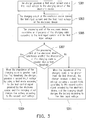
- FIG. 1 is a flowchart illustrating a charging method according to an embodiment of the invention.
- the charging method of FIG. 1 is applicable to an electronic system including an electronic device and a charger.
- step S101 when an electronic device is coupled to a charger, in step S101, the electronic device senses a first state of the electronic device itself. In step S103, the electronic device determines whether a value corresponding to the first state is greater than a first threshold. When the value corresponding to the first state is greater than the first threshold, in step S105, the electronic device provides a first control signal, and the charger charges the electronic device by using a first mode according to the first control signal. Moreover, when the value corresponding to the first state is not greater than the first threshold, in step S107, the electronic device provides a second control signal, and the charger charges the electronic device by using a second mode according to the second control signal.
- FIG. 2 is a schematic diagram illustrating an electronic system according to an embodiment of the invention.
- an electronic system 2000 includes an electronic device 200, a charger 220, and an external power 240.
- the electronic device 200 is a device such as a mobile phone, a personal digital assistant (PDA), a tablet computer, a wireless device, a wearable device, a watch, a portable electronic device, a handheld electronic device, a laptop, etc.
- the charger 220 is, for example, a power adapter. When the charger 220 is coupled to the electronic device 200 and the external power 240, the charger 220 converts an alternating current provided by the external power 240 into a direct current and charges the electronic device 200.
- the electronic device 200 includes a battery 201, a charging circuit 203, and a processing unit 205.
- the charging circuit 203 is coupled to the battery 201.
- the processing unit 205 is coupled to the battery and the charging circuit 203.
- the charging circuit 203 is coupled to the charger 220 via a charging cable.
- the battery 201 is a lithium battery or a rechargeable battery of another type.
- the charging circuit 203 is a circuit adapted to convert a voltage provided by the charging cable into an adequate voltage for charging the battery 201.
- the processing unit 205 is, for example, a central processing unit (CPU), a processor, a microprocessor, or an embedded controller (EC) of the electronic device 200.
- CPU central processing unit
- processor a processor
- microprocessor a microprocessor
- EC embedded controller
- the electronic device is charged by using a voltage-adjustable high-wattage charger with a charging cable that does not conform to a nominal impedance
- the voltage outputted by the charger is erroneously determined as a boost voltage due to the excessively high impedance of the charging cable.
- the charging circuit of the electronic device is caused to stop charging the battery due to the high voltage.
- the charger 220 is a voltage-adjustable high-wattage charger.
- the charger 220 simultaneously supports specifications such as Quick Charge 2.0 (QC 2.0) and Quick Charge 3.0 (QC 3.0) and charges the electronic device 200 by using one of Quick Charge 2.0 and Quick Charge 3.0 according to the impedance of the charging cable.
- FIG. 3 is a flowchart illustrating a charging method according to an embodiment of the invention.
- the charging method of FIG. 3 is applicable to the electronic system 2000 of FIG. 2 .
- the charger 220 converts an alternating current provided by the external power 240 into a direct current, and provides a first input current and a first input voltage to the charging circuit 203 of the electronic device 200 (step S301). Then, the charging circuit 203 of the electronic device 200 senses a first state of the electronic device 200, and the first state is the first input current and the first input voltage received by the charging circuit 203 (step S303).
- the processing unit 205 calculates an impedance of the charging cable according to the first input current and the first input voltage (step S305).
- the calculation of the impedance according to the current and the voltage may be learned from the prior art and is thus not repeatedly described here.
- the processing unit 205 determines whether the impedance of the charging cable is greater than a first threshold (step S307). Particularly, an optimal value of the first threshold is obtained through experiments, and the invention does not intend to limit the value of the first threshold.
- the processing unit 205 of the electronic device 200 provides a first control signal to the charger 220.
- the charger 220 provides a second input voltage by using a first mode according to the first control signal, and the charging circuit 203 charges the battery 201 according to the second input voltage (step S309).
- the first mode is Quick Charge 2.0.
- the standard of Quick Charge 2.0 predetermines a plurality of discontinuous default voltages, and the default voltages are fixed voltages (e.g., four voltages including 5V, 9V, 12V, and 20V).
- the charger 220 selects one voltage among the foregoing discontinuous default voltages as the second input voltage. For example, the charger 220 selects 5V as the second input voltage for charging the electronic device 200.
- the processing unit 205 of the electronic device 200 provides a second control signal to the charger 220.
- the charger 220 provides a third input voltage by using a second mode according to the second control signal, and the charging circuit 203 charges the battery 201 according to the third input voltage (step S311).
- the second mode is Quick Charge 3.0.
- the standard of Quick Charge 3.0 predetermines one continuous voltage interval, e.g., a voltage interval in a range of 3.6V to 20V.
- the processing unit 205 determines a voltage in the voltage interval to be the third input voltage (e.g., 3.9V) according to the first input current and provides the second control signal to the charger 220. Then, the charger 220 selects 3.9V in the continuous voltage interval as the third input voltage according to the second control signal.
- the charger 220 charges the electronic device 200 by using the third input voltage.
- the electronic system and the charging method of the first embodiment of the invention are capable of rapidly and accurately calculating the impedance.
- the charger 220 is controlled to output a corresponding voltage to allow the electronic device 200 to continue to quick charge. Accordingly, the issue that the electronic device 200 cannot charge due to the excessively high impedance of the charging cable is completely avoided, and user's experience and perception are improved.
- FIG. 4 is a schematic diagram illustrating an electronic system according to an embodiment of the invention.
- an electronic system 4000 includes an electronic device 400, a charger 420, and an external power 440.
- the electronic device 400 is a device such as a mobile phone, a personal digital assistant (PDA), a tablet computer, a wireless device, a wearable device, a watch, a portable electronic device, a handheld electronic device, a laptop, etc.
- the charger 420 is, for example, a power adapter. When the charger 420 is coupled to the electronic device 400 and the external power 440, the charger 420 converts an alternating current provided by the external power 440 into a direct current and charges the electronic device 400.
- the electronic device 400 includes a battery 401, a processing unit 403, a third converter 405, and a switch 407.
- the third converter 405 and the switch 407 are respectively coupled to the battery 401.
- the processing unit 403 is coupled to the battery 401, the switch 407, and the third converter 405.
- FIG. 4 does not illustrate the coupling relationship between the processing unit 403 and the third converter 405.
- the battery 401 and the processing unit 403 are respectively components that are similar to the foregoing battery 201 and the processing unit 205 and are thus not repeatedly described here.
- the third converter 405 is a converter adapted to convert a voltage and a current from the charger 420 into adequate voltage and current for charging the battery 401.
- the switch 407 is, for example, a switch circuit.
- the switch circuit is, for example, a MOSFT switch or a switch of another type that is switchable between an on-state and an off-state according to a control signal.
- the charger 420 includes a first converter 421, a second converter 423, and a controller 425.
- the controller 425 is coupled to the first converter 421 and the second converter 423.
- the controller 425 is a component that is similar to the foregoing processing unit 205 and is thus not repeatedly described here.
- the first converter 421 and the second converter 423 are converters adapted to convert an alternating current from the external power 440 into a direct current to supply power to the electronic device 400 for charging.
- the controller 425 is switchable between the first converter 421 and the second converter 423.
- the controller 425 may select to use the first converter 421 to provide a direct current to the electronic device 400 or use the second converter 423 to provide a direct current to the electronic device 400.
- the direct current provided by the first converter 421 and the direct current provided by the second converter 423 are different from each other.
- the controller 425 uses the first converter 421 to convert a power provided by the external power 440 into 5V and 2A and provides the converted power to the electronic device 400.
- the controller 425 may also use the second converter 421 to convert the power of the external power 440 into 3.6V and 2.5A and provide the converted power to the electronic device 400.
- the first converter 421 of the charger 420 is coupled to the third converter 405 of the electronic device 400
- the second converter 405 of the charger 420 is coupled to the switch 407 of the electronic device 400
- the controller 425 of the charger 420 is coupled to the processing unit 403 of the electronic device 400.
- the electronic device 400 When the controller 425 is coupled to the electronic device 400 via the charging cable, the electronic device 400 senses that the charger 420 connected thereto includes at least two converters (i.e., the first converter 421 and the second converter 423).
- the processing unit 403 of the electronic device 400 controls switching between the first converter 421 and the second converter 423 according to a state of the electronic device 400 in use (during charging).
- a path (also referred to as a second path) formed by the second converter 423 and the switch 407 is in an off-state.
- the charger 420 charges the battery 401 through a path (also referred to as a first path) formed by the first converter 421 and the third converter 405.
- the first converter 421 of the charger 420 first converts the power of the external power 440 into 5V/2A or 9V/1.67A. Then, the power of 5V/2A or 9V/1.67A is converted by the third converter 405 to further convert 5V/2A or 9V/1.67A into a voltage that is appropriate for charging the battery 401 using 3A.
- the second path formed by the second converter 423 and the switch 407 is in an on-state.
- the charger 425 uses the second path formed by the second converter 423 and the switch 407 to charge the battery 401.
- the second converter 423 of the charger 420 first converts the power of the external power 440 into a voltage of 3.6V to 5.2V and 2.5A. Then, the power converted by the second converter 423 is directly provided to the battery 401 via the switch 407 to charge the battery 401. In other words, the electronic device 400 does not further convert the power received from the charger 420.
- the switch 407 of the electronic device 400 is in the opened-state.
- the charger 420 uses the first path formed by the first converter 421 and the third converter 405 to charge the battery 401. At this time, the charger 420 provides a higher current to the electronic device 400.
- the foregoing method of charging using the first path may be referred to as a "second mode”
- the foregoing method of charging using the second path may be referred to as a "first mode”.
- the third converter 405 converts the power from the charger 420 into a voltage or current desired by the electronic device 400, part of the power may be lost and converted into heat. At this time, a temperature of the third converter 405 rises. When the temperature of the third converter 405 increases, the electronic device 400 may overheat. Moreover, when the processing unit 403 processes a great amount of data, uses different sensors to sense the environment, or uses an antenna to transmit data, these operations all cause a temperature of the electronic device 400 to rise.
- the processing unit 403 determines whether the electronic device 400 overheats or is to overheat. When the electronic device 400 overheats or is to overheat, the processing unit 403 sends a control command to turn off the switch 407 and instructs the controller 425 to switch from the first converter 421 to the second converter 423. Afterwards, the charger 420 charges the battery 401 via the second path. Accordingly, the third converter 405 is prevented from constantly generating heat and causing the temperature of the electronic device 400 to continue to rise.
- the determination on whether the device is to overheat may be based on comprehensive evaluations of the following: whether the electronic device 400 turns on a plurality of specific components, e.g., a GPS sensor, WIFI, a 3G or 4G Internet antenna, a Bluetooth antenna, a camera, an ultrasonic transmitter, a radar transmitter, a current output device, etc.; or whether a memory usage rate exceeds a predetermined value (e.g., the memory usage rate exceeds 70%), or a specific application (e.g., Facebook application, a map application, a game application, a camera application, etc.) is turned on.
- the determination method may be different combinations of the foregoing determination criteria (e.g., when the camera application and the GPS sensor are simultaneously turned on).
- the foregoing different determination criteria or the combinations thereof are used to predict whether the electronic device 400 will have the issue of overheating some time in the future, so that different charging methods can be used during charging.
- the determination criteria may additionally apply with different sensors (e.g., a temperature sensor provided close to the processing unit 403, a memory unit, or a battery unit) to sense a current state of the electronic device 400. Based on the current state of the electronic device 400, the foregoing determination criteria are used to determine whether the electronic device 400 will have the issue of overheating some time in the future.
- the foregoing determination criteria or the combinations thereof may be stored in a memory.
- the processing unit 403 reads data stored in the memory.
- the processing unit 403 determines whether to perform the switching based on the stored data.
- the processing unit 403 also determines whether the electronic device 400 will have the issue of overheating some time in the future and sets a time point for switching the charging method.
- the temperature sensor provided on the processing unit 403 senses that the processing unit 403 is 100 degrees (°C) and the GPS sensors is activated for operation, and the activation of the GPS sensor causes the temperature of the electronic device 400 to rise by 10 degrees every 10 minutes.
- the processing unit 403 may be set to automatically switch the charging method 9 minutes later to prevent the processing unit 403 from exceeding a working temperature. Conversely, for example, if the temperature sensor provided on the processing unit 403 senses that the processing unit 403 is 110 degrees but the GPS sensor has stopped operating, and the deactivation of the GPS sensor causes the temperature of the electronic device 400 to drop by 10 degrees every 10 minutes, the processing unit 403 may be set to switch to a charging mode that generates higher heat within a predetermined time.
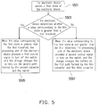
- FIG. 5 is a flowchart illustrating a charging method according to an embodiment of the invention.
- the charging method of FIG. 5 is applicable to the electronic system 4000 of FIG. 4 .
- the electronic device 400 senses a first state of the electronic device 400 (step S501). Then, the electronic device 400 determines whether a value corresponding to the first state is greater than a first threshold (step S503). When the value corresponding to the first state is greater than the first threshold, the processing unit 403 provides a first control signal to turn off the switch 407, and the charger 420 charges the battery 401 via the second path formed by the second converter 423 and the switch 407 (step S505).
- the processing unit 403 When the value corresponding to the first state is not greater than the first threshold, the processing unit 403 provides a second control signal to turn on the switch 407, and the charger 420 charges the battery 401 via the first path formed by the first converter 421 and the third converter 405 (step S507).
- a default state of the electronic device 400 is charging by using the first path (i.e., the switch 407 is in the opened-state).
- the electronic device 400 switches to use the second path for charging, the electronic device 400 continues to sense the first state.
- the electronic device 400 switches back to use the first path for charging.
- the electronic device 400 may also use the second path only for charging until the power of the battery 401 is fully charged.
- the first state may be a temperature of some one component in the electronic device 400 or an overall temperature of the electronic device 400 itself.
- the processing unit 403 senses the temperature of the electronic device 400 or the specific component by using a plurality of methods.
- the processing unit 403 is coupled to a temperature sensor to sense a temperature of multiple positions or specific positions.
- the positions are, for example, a position of the processing unit 403, a position of the battery 401, or a position of a communication unit (not illustrated).
- the processing unit 403 determines that the sensed temperature is higher than the threshold, the processing unit 403 provides the first control signal to turn off the switch 407 and charges the battery 401 via the second path.
- the processing unit 403 provides the second control signal to turn on the switch 407 to charge the battery 401 via the first path.
- the processing unit 403 since the electronic device 400 does not need to further convert the current and the voltage outputted by the second converter 423, the temperature of the electronic device 400 is effectively controlled to stop rising.
- the first state may also be the heat that may be generated by the electronic device 400 in the future.
- the processing unit 403 determines the heat that may be generated by the electronic device 400 in the future according to the sensors used or activated by the electronic device 400. It is known that when some sensors or circuits are activated, a great amount of heat is generated. For example, a user may use a positioning unit (not illustrated, e.g., a GPS module) to sense a position of the user or the electronic device 400. When the positioning unit is activated for a period of time, the processing unit 403 determines that the heat generated by the positioning unit will affect future use of the electronic device 400.
- a positioning unit not illustrated, e.g., a GPS module
- the communication unit e.g., a WiFi module
- an image capturing unit e.g., a camera module
- the processing unit 403 determines that the heat is greater than the threshold, the processing unit 403 provides the first control signal to turn off the switch 407 to charge the battery 401 via the second path. Otherwise, the processing unit 403 provides the second control signal to turn on the switch 407 to charge the battery 401 via the first path.
- the invention does not intend to limit how the heat of the electronic device is calculated. Moreover, the invention may also determine whether it is necessary to turn off the switch 407 to charge the battery 401 via the second path solely based on the heat that may be generated by one single component or part of the components in the future.
- the first state may also be a load of the electronic device 400.
- the load of the electronic device 400 may be determined according to a current consumed by the electronic device 400.
- the processing unit 403 uses a current sensor (not illustrated) to monitor the current consumed by the electronic device 400.
- the current sensor is, for example, provided in the processing unit 403, the battery 401, or the communication unit (not illustrated).
- the processing unit 403 senses that the current consumed by the electronic device 400 is greater than 400mA, the processing unit 403 provides the first control signal to turn off the switch 407 to charge the battery 401 via the second path. Otherwise, the processing unit 403 provides the second control signal to turn on the switch 407 to charge the battery 401 via the first path.
- the first state may also be a state of the battery 401.
- the processing unit 403 or the charging circuit of the electronic device 400 senses the state of the battery 401 (e.g., a state value corresponding to a voltage, a battery capacity, or a charging state). Based on the foregoing state value regarding the battery 401, the processing unit 403 also correspondingly changes the path for charging.
- the first state may also be a protection mechanism of the electronic device 400.
- the processing unit 403 or the charging circuit of the electronic device 400 senses an over voltage protection (OVP), an over power protection (OPP), an over load protection (OLP), or an over current protection (OCP), and determines whether the foregoing protection mechanisms occur according to corresponding reference values. Based on the occurrence of the foregoing protection mechanisms, the processing unit 403 also correspondingly changes the path for charging.
- OVP over voltage protection
- OPP over power protection
- OTP over load protection
- OCP over current protection
- the foregoing method mainly involves using hardware components to sense the first state of the electronic device to obtain the value corresponding to the first state.
- the first state may also be sensed by using software.
- the processing unit 403 determines the heat generated by a loading or operating software program.
- the software program is, for example, a map service program, a game program, a camera program, a video-recording program, social networking software, etc.
- the foregoing software programs When the foregoing software programs are loaded or executed, they may consume more power and generate more heat.
- software that turns on specific components is all software that easily generates heat.
- Such software is, for example, the foregoing map program, cameral program, video-recording program, etc.
- the processing unit 403 determines that the foregoing software is turned on, the processing unit 403 provides the first control signal to turn off the switch 407 to charge the battery 401 via the second path.
- the processing unit 403 determines that the software is turned off, the processing unit 403 provides the second control signal to turn on the switch 407 to charge the battery 401 via the first path.
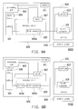
- FIG. 6A is a schematic diagram illustrating an electronic system according to an embodiment of the invention.
- an electronic system 6000 includes an electronic device 600, a charger 620, and an external power 640.
- the electronic device 600 includes a battery 601, a processing unit 603, a charging circuit 605, a switch 607, a sensor 609, and a sensor 611.
- the charging circuit 605 and the switch 607 are respectively coupled to the battery 601.
- the battery 601 is coupled to the sensor 609.
- the processing unit 603 is coupled to the charging circuit 605, the switch 607, the sensor 609, and the sensor 611.
- the battery 601, the processing unit 603, and the switch 607 are respectively components that are similar to the foregoing battery 201, processing unit 205, and switch 407 and are thus not repeatedly described here.
- the charging circuit 605 further includes a third converter 605a.
- the third converter 605a is adapted to execute a function similar to that of the foregoing third converter 405.
- the sensor 609 is provided between the processing unit 603 and the battery 601 to measure a power provided by the battery 601 to the processing unit 609.
- the sensor 611 is, for example, a temperature sensor or a sensor of another function, e.g., a camera, an optic sensor, a proximity sensor, etc.
- the processing unit 603 also includes a sensor (not illustrated) therein.
- the sensor senses a load of the processing unit 603 or the temperature sensor to sense a heat in the processing unit 603 or the electronic device 600.
- the charger 620 includes a controller 623 and a fourth converter 621.
- the fourth converter 621 includes the first converter 421 and the second converter 423 of FIG. 4 or simultaneously has the functions of the first converter 421 and the second converter 423.
- the controller 623 controls the fourth converter 621 to convert a power of the external power 640 into a different power to provide power to the third converter 605a of the charging circuit 605 or the switch 607 to charge the battery 601.
- the fourth converter 621 and the third converter 605a form the foregoing first path
- the fourth converter 621 outputs the converted voltage and current to the third converter 605a to charge the battery 601 via the first path
- the fourth converter 621 and the switch 607 form the foregoing second path
- the fourth converter 621 outputs the current and voltage to charge the battery 601 via the second path formed by the fourth converter 621 and the switch 607.
- the electronic device 600 since the electronic device 600 does not need to further convert the current and the voltage outputted by the fourth converter 621, a temperature of the electronic device 600 is effectively controlled to stop rising.
- FIG. 6B is a schematic diagram illustrating an electronic system according to an embodiment of the invention.
- an electronic system 6100 of FIG. 6B is substantially identical to the electronic system 6000 of FIG. 6A .
- the charging circuit 605 of FIG. 6B includes a sensor 605b coupled to the third converter 605a and the battery 601.
- the sensor 605b is adapted to sense a current or voltage provided to the battery.
- FIG. 6A and FIG. 6B only illustrate the electronic systems that are applicable to the charging method of FIG. 5 .
- the invention is not limited hereto.
- the electronic system applicable to the charging method of FIG. 5 may include more or less components.
- FIG. 7 is a schematic diagram illustrating performance of a charging method of the invention according to an embodiment of the invention.
- FIG. 7 illustrates the switching between the first path and the second path during charging.
- the charger In the initial state, when the charger is connected to the electronic device, the charger outputs a power having a high current (e.g., 3A) via the first path to the electronic device. This power is converted by the first converter in the first path.
- the third converter in the electronic device generates heat due to power conversion.
- the temperature of the electronic device constantly rises.
- a conventional converter as a line segment 700 shows, as the temperature rises, the converter in the conventional charger can continually provide the maximum current (i.e., 3A as indicated above). At this time, the converter in the electronic device may generate more heat, causing the temperature of the electronic device to constantly rise.
- the converter of the charger lowers the outputted current to reduce the heat generated by the converter of the electronic device.
- the same converter in the electronic device is invariably used in the line segment 710 to charge the battery, when the converter is continually used for charging, the converter still causes the temperature of the electronic device to continue to rise.
- the switch of the electronic device when switched to the second path to charge the electronic device, does not convert the power inputted to the electronic device. In other words, this method removes the heat generated by the converter (i.e., the foregoing first converter) in the electronic device.
- the charger uses the first path to output a power of a high current (e.g., 3A) to the electronic device.
- the electronic device uses the first converter to convert the power of the higher current.
- a threshold e.g., the value Y
- the charger turns off the switch to charge the battery via the second path without passing the first converter in the first path.
- the first converter since the first converter is disabled, the first converter does not continue to generate heat.
- the electronic device switches back to the first path to continue to charge in a high current (e.g., 3A).
- the charger may also continue to use the second path to charge the battery until the battery is fully charged.
- the charger may also constantly switch between the first path and the second path during charging until the battery is fully charged. As FIG. 7 shows, compared to the conventional charger, the charging method of the invention more rapidly completes the charging and effectively inhibits rise in the temperature of the electronic device.
- the first exemplary embodiment and the second exemplary embodiment of the invention may be combined with each other.
- an impedance of the charging cable is first determined to determine whether to use Quick Charge 2.0 or Quick Charge 3.0 for charging.
- the electronic device may constantly sense the first state of the electronic device itself to determine whether to use the first path or the second path for charging.
- the electronic system and the charging method of the invention adopt different modes to charge the electronic device according to the variations in the state of the electronic device. Accordingly, the electronic device is rapidly charged and the user is provided with a more desirable experience.
Landscapes
- Physics & Mathematics (AREA)
- General Physics & Mathematics (AREA)
- Charge And Discharge Circuits For Batteries Or The Like (AREA)
Applications Claiming Priority (2)
| Application Number | Priority Date | Filing Date | Title |
|---|---|---|---|
| US201662319806P | 2016-04-08 | 2016-04-08 | |
| US15/473,562 US20170294794A1 (en) | 2016-04-08 | 2017-03-29 | Electronic system and charging method |
Publications (2)
| Publication Number | Publication Date |
|---|---|
| EP3229338A2 true EP3229338A2 (de) | 2017-10-11 |
| EP3229338A3 EP3229338A3 (de) | 2018-01-31 |
Family
ID=59021214
Family Applications (1)
| Application Number | Title | Priority Date | Filing Date |
|---|---|---|---|
| EP17164867.8A Withdrawn EP3229338A3 (de) | 2016-04-08 | 2017-04-04 | Elektronisches system und ladeverfahren |
Country Status (4)
| Country | Link |
|---|---|
| US (1) | US20170294794A1 (de) |
| EP (1) | EP3229338A3 (de) |
| CN (1) | CN107276145B (de) |
| TW (1) | TWI643423B (de) |
Families Citing this family (9)
| Publication number | Priority date | Publication date | Assignee | Title |
|---|---|---|---|---|
| US11119142B1 (en) * | 2018-02-05 | 2021-09-14 | Amazon Technologies, Inc. | Automated cable assessment and control |
| TWI663514B (zh) * | 2018-04-27 | 2019-06-21 | 宏碁股份有限公司 | 電子裝置及其溫度控制方法 |
| CN110825202B (zh) * | 2018-08-07 | 2023-04-28 | 技嘉科技股份有限公司 | 具有智能充电功能的主机板 |
| CN110858093A (zh) * | 2018-08-07 | 2020-03-03 | 技嘉科技股份有限公司 | 具有充电功能的主机板 |
| CN111900769B (zh) * | 2019-05-06 | 2024-10-29 | 华为技术有限公司 | 一种充电控制电路及电子设备 |
| CN113009995B (zh) * | 2019-12-20 | 2023-10-20 | 华为技术有限公司 | 一种供电装置及供电方法 |
| CN113765165A (zh) * | 2020-06-03 | 2021-12-07 | 北京小米移动软件有限公司 | 充电接口及充电接口的保护方法、保护装置及存储介质 |
| CN115566744A (zh) * | 2021-07-01 | 2023-01-03 | 北京小米移动软件有限公司 | 用于电子设备的充电控制方法、装置、电子设备及介质 |
| TWI857364B (zh) * | 2022-10-13 | 2024-10-01 | 宏碁股份有限公司 | 電子裝置及其充電方法 |
Family Cites Families (11)
| Publication number | Priority date | Publication date | Assignee | Title |
|---|---|---|---|---|
| US7834591B2 (en) * | 2006-02-16 | 2010-11-16 | Summit Microelectronics, Inc. | Switching battery charging systems and methods |
| JP2011205758A (ja) * | 2010-03-25 | 2011-10-13 | Fuji Heavy Ind Ltd | 充電装置 |
| US9071067B2 (en) * | 2011-05-12 | 2015-06-30 | Lenovo (Singapore) Pte. Ltd. | Fast battery charging system and method |
| US9312576B2 (en) * | 2012-02-15 | 2016-04-12 | Htc Corporation | Portable electronic devices capable of obtaining charging current value of charger and charging method thereof |
| JP2015104225A (ja) * | 2013-11-25 | 2015-06-04 | ソニー株式会社 | 蓄電システムおよび二次電池の充電方法 |
| US9158325B1 (en) * | 2014-04-22 | 2015-10-13 | Infineon Technologies Ag | Cable quality detection and power consumer devices |
| US20150362944A1 (en) * | 2014-06-13 | 2015-12-17 | Qualcomm Incorporated | Systems and methods for cable resistance compensation |
| CN104065126B (zh) * | 2014-06-27 | 2017-01-25 | 宇龙计算机通信科技(深圳)有限公司 | 一种充电器、终端和充电方法 |
| US9728983B2 (en) * | 2014-12-09 | 2017-08-08 | Verizon Patent And Licensing Inc. | Weak component detection for charging capacity control |
| CN104967201B (zh) * | 2015-08-05 | 2018-10-02 | 青岛海信移动通信技术股份有限公司 | 快速充电方法、移动终端及可直充电源适配器 |
| CN104993182B (zh) * | 2015-08-05 | 2018-01-09 | 青岛海信移动通信技术股份有限公司 | 一种移动终端、可直充电源适配器及充电方法 |
-
2017
- 2017-03-29 US US15/473,562 patent/US20170294794A1/en not_active Abandoned
- 2017-03-30 TW TW106110699A patent/TWI643423B/zh active
- 2017-04-04 EP EP17164867.8A patent/EP3229338A3/de not_active Withdrawn
- 2017-04-07 CN CN201710225119.2A patent/CN107276145B/zh active Active
Non-Patent Citations (1)
| Title |
|---|
| None |
Also Published As
| Publication number | Publication date |
|---|---|
| EP3229338A3 (de) | 2018-01-31 |
| US20170294794A1 (en) | 2017-10-12 |
| TW201737586A (zh) | 2017-10-16 |
| CN107276145A (zh) | 2017-10-20 |
| TWI643423B (zh) | 2018-12-01 |
| CN107276145B (zh) | 2021-01-12 |
Similar Documents
| Publication | Publication Date | Title |
|---|---|---|
| EP3229338A2 (de) | Elektronisches system und ladeverfahren | |
| US10910870B2 (en) | Charging device and charging method | |
| JP4299309B2 (ja) | 蓄電池の充電システムおよび充電方法 | |
| US10797358B2 (en) | Smart power bank system for efficient energy transfer | |
| JP4805223B2 (ja) | 充電システムおよび充電方法 | |
| TWI427892B (zh) | 具省電功能之供電系統及供電方法 | |
| US20160099608A1 (en) | Power adapter with built-in battery and power storage and supply method thereof | |
| JP7121865B2 (ja) | 逆方向充電装置、逆方向充電電流調整方法及び装置 | |
| US20110074360A1 (en) | Power adapter with internal battery | |
| US20080238358A1 (en) | Electronic apparatus, charging method therefor, and battery | |
| JP6799754B2 (ja) | バッテリ制御装置、電子機器、バッテリパック及びバッテリ制御方法 | |
| WO2007122787A1 (ja) | 充電システム、充電制御プログラムおよび携帯端末 | |
| JP2009153238A (ja) | 携帯機器と、携帯機器に用いる電池パック | |
| US20150089260A1 (en) | Electronic Apparatus, Method, and Storage Medium | |
| US9252618B2 (en) | Terminals, terminal systems and charging/discharging methods thereof | |
| US10879737B2 (en) | Control device, power receiving device, and electronic device | |
| US20080309291A1 (en) | Computer system and control method thereof | |
| JP2019175755A (ja) | 回路装置、制御装置、受電装置及び電子機器 | |
| KR101835007B1 (ko) | 휴대용 단말기에서 충전 전류를 제어하기 위한 장치 및 방법 | |
| KR20060107554A (ko) | 배터리들을 충전하는 방법 및 시스템 | |
| US20200313442A1 (en) | Multi-power management system and multi-power management method | |
| JP3922989B2 (ja) | 充電制御装置及び充電制御方法 | |
| US20220344965A1 (en) | Electronic device, accessory, method and program for operating electronic device, and method and program for operating accessory | |
| JP2015076954A (ja) | 電子機器および情報処理システム | |
| WO2022242347A1 (zh) | 无线充电方法、装置及存储介质 |
Legal Events
| Date | Code | Title | Description |
|---|---|---|---|
| PUAI | Public reference made under article 153(3) epc to a published international application that has entered the european phase |
Free format text: ORIGINAL CODE: 0009012 |
|
| 17P | Request for examination filed |
Effective date: 20170404 |
|
| AK | Designated contracting states |
Kind code of ref document: A2 Designated state(s): AL AT BE BG CH CY CZ DE DK EE ES FI FR GB GR HR HU IE IS IT LI LT LU LV MC MK MT NL NO PL PT RO RS SE SI SK SM TR |
|
| AX | Request for extension of the european patent |
Extension state: BA ME |
|
| PUAL | Search report despatched |
Free format text: ORIGINAL CODE: 0009013 |
|
| AK | Designated contracting states |
Kind code of ref document: A3 Designated state(s): AL AT BE BG CH CY CZ DE DK EE ES FI FR GB GR HR HU IE IS IT LI LT LU LV MC MK MT NL NO PL PT RO RS SE SI SK SM TR |
|
| AX | Request for extension of the european patent |
Extension state: BA ME |
|
| RIC1 | Information provided on ipc code assigned before grant |
Ipc: H02J 7/00 20060101AFI20171222BHEP Ipc: H02J 7/04 20060101ALI20171222BHEP |
|
| 17Q | First examination report despatched |
Effective date: 20180129 |
|
| RBV | Designated contracting states (corrected) |
Designated state(s): AL AT BE BG CH CY CZ DE DK EE ES FI FR GB GR HR HU IE IS IT LI LT LU LV MC MK MT NL NO PL PT RO RS SE SI SK SM TR |
|
| STAA | Information on the status of an ep patent application or granted ep patent |
Free format text: STATUS: THE APPLICATION IS DEEMED TO BE WITHDRAWN |
|
| 18D | Application deemed to be withdrawn |
Effective date: 20200603 |