EP3228929A1 - Fahrzeugscheinwerfervorrichtung - Google Patents
Fahrzeugscheinwerfervorrichtung Download PDFInfo
- Publication number
- EP3228929A1 EP3228929A1 EP17156556.7A EP17156556A EP3228929A1 EP 3228929 A1 EP3228929 A1 EP 3228929A1 EP 17156556 A EP17156556 A EP 17156556A EP 3228929 A1 EP3228929 A1 EP 3228929A1
- Authority
- EP
- European Patent Office
- Prior art keywords
- light
- optical member
- emitting face
- mirror
- collecting optical
- Prior art date
- Legal status (The legal status is an assumption and is not a legal conclusion. Google has not performed a legal analysis and makes no representation as to the accuracy of the status listed.)
- Withdrawn
Links
Images

Classifications
-
- F—MECHANICAL ENGINEERING; LIGHTING; HEATING; WEAPONS; BLASTING
- F21—LIGHTING
- F21S—NON-PORTABLE LIGHTING DEVICES; SYSTEMS THEREOF; VEHICLE LIGHTING DEVICES SPECIALLY ADAPTED FOR VEHICLE EXTERIORS
- F21S41/00—Illuminating devices specially adapted for vehicle exteriors, e.g. headlamps
- F21S41/30—Illuminating devices specially adapted for vehicle exteriors, e.g. headlamps characterised by reflectors
- F21S41/32—Optical layout thereof
- F21S41/36—Combinations of two or more separate reflectors
-
- B—PERFORMING OPERATIONS; TRANSPORTING
- B60—VEHICLES IN GENERAL
- B60Q—ARRANGEMENT OF SIGNALLING OR LIGHTING DEVICES, THE MOUNTING OR SUPPORTING THEREOF OR CIRCUITS THEREFOR, FOR VEHICLES IN GENERAL
- B60Q1/00—Arrangement of optical signalling or lighting devices, the mounting or supporting thereof or circuits therefor
- B60Q1/02—Arrangement of optical signalling or lighting devices, the mounting or supporting thereof or circuits therefor the devices being primarily intended to illuminate the way ahead or to illuminate other areas of way or environments
- B60Q1/04—Arrangement of optical signalling or lighting devices, the mounting or supporting thereof or circuits therefor the devices being primarily intended to illuminate the way ahead or to illuminate other areas of way or environments the devices being headlights
- B60Q1/06—Arrangement of optical signalling or lighting devices, the mounting or supporting thereof or circuits therefor the devices being primarily intended to illuminate the way ahead or to illuminate other areas of way or environments the devices being headlights adjustable, e.g. remotely-controlled from inside vehicle
- B60Q1/08—Arrangement of optical signalling or lighting devices, the mounting or supporting thereof or circuits therefor the devices being primarily intended to illuminate the way ahead or to illuminate other areas of way or environments the devices being headlights adjustable, e.g. remotely-controlled from inside vehicle automatically
-
- F—MECHANICAL ENGINEERING; LIGHTING; HEATING; WEAPONS; BLASTING
- F21—LIGHTING
- F21S—NON-PORTABLE LIGHTING DEVICES; SYSTEMS THEREOF; VEHICLE LIGHTING DEVICES SPECIALLY ADAPTED FOR VEHICLE EXTERIORS
- F21S41/00—Illuminating devices specially adapted for vehicle exteriors, e.g. headlamps
- F21S41/10—Illuminating devices specially adapted for vehicle exteriors, e.g. headlamps characterised by the light source
- F21S41/14—Illuminating devices specially adapted for vehicle exteriors, e.g. headlamps characterised by the light source characterised by the type of light source
- F21S41/141—Light emitting diodes [LED]
- F21S41/151—Light emitting diodes [LED] arranged in one or more lines
- F21S41/153—Light emitting diodes [LED] arranged in one or more lines arranged in a matrix
-
- F—MECHANICAL ENGINEERING; LIGHTING; HEATING; WEAPONS; BLASTING
- F21—LIGHTING
- F21S—NON-PORTABLE LIGHTING DEVICES; SYSTEMS THEREOF; VEHICLE LIGHTING DEVICES SPECIALLY ADAPTED FOR VEHICLE EXTERIORS
- F21S41/00—Illuminating devices specially adapted for vehicle exteriors, e.g. headlamps
- F21S41/10—Illuminating devices specially adapted for vehicle exteriors, e.g. headlamps characterised by the light source
- F21S41/14—Illuminating devices specially adapted for vehicle exteriors, e.g. headlamps characterised by the light source characterised by the type of light source
- F21S41/16—Laser light sources
-
- F—MECHANICAL ENGINEERING; LIGHTING; HEATING; WEAPONS; BLASTING
- F21—LIGHTING
- F21S—NON-PORTABLE LIGHTING DEVICES; SYSTEMS THEREOF; VEHICLE LIGHTING DEVICES SPECIALLY ADAPTED FOR VEHICLE EXTERIORS
- F21S41/00—Illuminating devices specially adapted for vehicle exteriors, e.g. headlamps
- F21S41/10—Illuminating devices specially adapted for vehicle exteriors, e.g. headlamps characterised by the light source
- F21S41/14—Illuminating devices specially adapted for vehicle exteriors, e.g. headlamps characterised by the light source characterised by the type of light source
- F21S41/176—Light sources where the light is generated by photoluminescent material spaced from a primary light generating element
-
- F—MECHANICAL ENGINEERING; LIGHTING; HEATING; WEAPONS; BLASTING
- F21—LIGHTING
- F21S—NON-PORTABLE LIGHTING DEVICES; SYSTEMS THEREOF; VEHICLE LIGHTING DEVICES SPECIALLY ADAPTED FOR VEHICLE EXTERIORS
- F21S41/00—Illuminating devices specially adapted for vehicle exteriors, e.g. headlamps
- F21S41/20—Illuminating devices specially adapted for vehicle exteriors, e.g. headlamps characterised by refractors, transparent cover plates, light guides or filters
- F21S41/24—Light guides
-
- F—MECHANICAL ENGINEERING; LIGHTING; HEATING; WEAPONS; BLASTING
- F21—LIGHTING
- F21S—NON-PORTABLE LIGHTING DEVICES; SYSTEMS THEREOF; VEHICLE LIGHTING DEVICES SPECIALLY ADAPTED FOR VEHICLE EXTERIORS
- F21S41/00—Illuminating devices specially adapted for vehicle exteriors, e.g. headlamps
- F21S41/20—Illuminating devices specially adapted for vehicle exteriors, e.g. headlamps characterised by refractors, transparent cover plates, light guides or filters
- F21S41/25—Projection lenses
-
- F—MECHANICAL ENGINEERING; LIGHTING; HEATING; WEAPONS; BLASTING
- F21—LIGHTING
- F21S—NON-PORTABLE LIGHTING DEVICES; SYSTEMS THEREOF; VEHICLE LIGHTING DEVICES SPECIALLY ADAPTED FOR VEHICLE EXTERIORS
- F21S41/00—Illuminating devices specially adapted for vehicle exteriors, e.g. headlamps
- F21S41/20—Illuminating devices specially adapted for vehicle exteriors, e.g. headlamps characterised by refractors, transparent cover plates, light guides or filters
- F21S41/285—Refractors, transparent cover plates, light guides or filters not provided in groups F21S41/24 - F21S41/2805
-
- F—MECHANICAL ENGINEERING; LIGHTING; HEATING; WEAPONS; BLASTING
- F21—LIGHTING
- F21S—NON-PORTABLE LIGHTING DEVICES; SYSTEMS THEREOF; VEHICLE LIGHTING DEVICES SPECIALLY ADAPTED FOR VEHICLE EXTERIORS
- F21S41/00—Illuminating devices specially adapted for vehicle exteriors, e.g. headlamps
- F21S41/40—Illuminating devices specially adapted for vehicle exteriors, e.g. headlamps characterised by screens, non-reflecting members, light-shielding members or fixed shades
- F21S41/47—Attachment thereof
-
- F—MECHANICAL ENGINEERING; LIGHTING; HEATING; WEAPONS; BLASTING
- F21—LIGHTING
- F21S—NON-PORTABLE LIGHTING DEVICES; SYSTEMS THEREOF; VEHICLE LIGHTING DEVICES SPECIALLY ADAPTED FOR VEHICLE EXTERIORS
- F21S41/00—Illuminating devices specially adapted for vehicle exteriors, e.g. headlamps
- F21S41/60—Illuminating devices specially adapted for vehicle exteriors, e.g. headlamps characterised by a variable light distribution
- F21S41/65—Illuminating devices specially adapted for vehicle exteriors, e.g. headlamps characterised by a variable light distribution by acting on light sources
- F21S41/663—Illuminating devices specially adapted for vehicle exteriors, e.g. headlamps characterised by a variable light distribution by acting on light sources by switching light sources
-
- F—MECHANICAL ENGINEERING; LIGHTING; HEATING; WEAPONS; BLASTING
- F21—LIGHTING
- F21S—NON-PORTABLE LIGHTING DEVICES; SYSTEMS THEREOF; VEHICLE LIGHTING DEVICES SPECIALLY ADAPTED FOR VEHICLE EXTERIORS
- F21S41/00—Illuminating devices specially adapted for vehicle exteriors, e.g. headlamps
- F21S41/60—Illuminating devices specially adapted for vehicle exteriors, e.g. headlamps characterised by a variable light distribution
- F21S41/67—Illuminating devices specially adapted for vehicle exteriors, e.g. headlamps characterised by a variable light distribution by acting on reflectors
- F21S41/675—Illuminating devices specially adapted for vehicle exteriors, e.g. headlamps characterised by a variable light distribution by acting on reflectors by moving reflectors
-
- F—MECHANICAL ENGINEERING; LIGHTING; HEATING; WEAPONS; BLASTING
- F21—LIGHTING
- F21Y—INDEXING SCHEME ASSOCIATED WITH SUBCLASSES F21K, F21L, F21S and F21V, RELATING TO THE FORM OR THE KIND OF THE LIGHT SOURCES OR OF THE COLOUR OF THE LIGHT EMITTED
- F21Y2115/00—Light-generating elements of semiconductor light sources
- F21Y2115/10—Light-emitting diodes [LED]
-
- F—MECHANICAL ENGINEERING; LIGHTING; HEATING; WEAPONS; BLASTING
- F21—LIGHTING
- F21Y—INDEXING SCHEME ASSOCIATED WITH SUBCLASSES F21K, F21L, F21S and F21V, RELATING TO THE FORM OR THE KIND OF THE LIGHT SOURCES OR OF THE COLOUR OF THE LIGHT EMITTED
- F21Y2115/00—Light-generating elements of semiconductor light sources
- F21Y2115/30—Semiconductor lasers
Definitions
- the present invention relates to a vehicle headlight device.
- vehicular digital lighting system which includes an optical engine, a reflection type digital light deflector, a light irradiation device, a storage device, a surrounding environment detecting device, and a control device.
- the optical engine reflects light from a discharge lamp (light source) using a reflector to guide the light to a collimator lens where the light is changed to parallel light. Since the reflection type digital light deflector digitally switches the inclined angles of many tiny mirror elements, the parallel light from the collimator lens can be reflected to switch the reflected light in two on/off directions so as to form a light distribution pattern on the side of the light irradiation device.
- a vehicular lighting device which includes a light source module, a relay lens module, a light valve, a sensing unit, a projection lens module, and a control unit.
- the light valve has a micromirror that controls the reflection direction or passage of a light flux to make light emitted from the light source enter the micromirror so that the light will be reflected and projected from the projection lens module.
- the present invention has been made in view of the circumstances, and it is an object thereof to provide a vehicle headlight device capable of forming a light distribution pattern efficiently with a simple structure.
- a vehicle headlight device of a first invention which includes: a light-emitting face on which at least one light-emitting element is arranged; a light-collecting optical member which collects light emitted from the light-emitting face; a collection mirror configured by arranging plural inclinable mirror elements in such a manner that light entering from the light-collecting optical member is reflected by each of the mirror elements; a projection optical member which projects a light distribution pattern of light reflected by the collection mirror to an irradiated area ahead of a vehicle; and a control unit which performs processing to control inclined states of the plural mirror elements of the collection mirror to change an illumination distribution of the light distribution pattern, wherein a shape of the light-emitting face and a shape of the collection mirror are similar to each other.
- the light emitted from the light-emitting face is collected by the light-collecting optical member to enter the collection mirror. Then, the collection mirror reflects the light entering from the light-collecting optical member toward the projection optical member.
- the control unit can control the inclined states of the plural mirror elements to form a predetermined light distribution pattern in the irradiated area.
- the device can form a light distribution pattern efficiently with a simple structure.
- the vehicle headlight device of the first invention is also characterized in that, when distortion of the light-collecting optical member is a positive value, the size of the light-emitting face is set smaller than a theoretical size calculated based on a ratio b/a of distance a between the light-emitting face and the light-collecting optical member, and distance b between the light-collecting optical member and the collection mirror, and an irradiated area set on the collection mirror, and when the distortion of the light-collecting optical member is a negative value, the size of the light-emitting face is set larger than the theoretical size (a second invention).
- the irradiated area of the light entering the collection mirror is calculated as a product of the ratio b/a (magnifying power) of the distance a between the light-emitting face and the light-collecting optical member, and the distance b between the light-collecting optical member and the collection mirror, and the size of the light-emitting face.
- the distortion of the light-collecting optical member is a positive value
- the light emitted from the light-emitting face is distorted and hence becomes larger than the irradiated area set on the mirror. Therefore, the size of the light-emitting face is set smaller than the theoretical size so that the light will fit within the irradiated area even when the light is distorted.
- the device can adjust the size of the irradiated area on the collection mirror. Further, since the light-emitting face and the collection mirror are similar in shape to each other, the device also has the advantage of being able to form a light distribution pattern easily.
- a vehicle headlight device of a third invention which includes: a light-emitting face on which at least one light-emitting element is arranged; a light-collecting optical member which collects light emitted from the light-emitting face; a collection mirror configured by arranging plural inclinable mirror elements in such a manner that light entering from the light-collecting optical member is reflected by each of the mirror elements; a projection optical member which projects a light distribution pattern of light reflected by the collection mirror to an irradiated area ahead of a vehicle; and a control unit which performs processing to control inclined states of the plural mirror elements of the collection mirror to change an illumination distribution of the light distribution pattern, wherein, when distortion of the light-collecting optical member is a positive value, the size of the light-emitting face is set smaller than a theoretical size calculated based on a ratio b/a of distance a between the light-emitting face and the light-collecting optical member, and distance b between the light-collecting optical member and the collection mirror, and
- the light emitted from the light-emitting face is collected by the light-collecting optical member to enter the collection mirror. Then, the collection mirror reflects the light entering from the light-collecting optical member toward the projection optical member.
- the control unit controls the inclined states of the plural mirror elements, and this enables the device to form a predetermined light distribution pattern in the irradiated area.
- the device can adjust the size of the irradiated area on the collection mirror.
- the vehicle headlight device of the first invention is further characterized in that the light-emitting element is a laser diode or a light-emitting diode (a fourth invention).
- the light-emitting element is a laser diode or a light-emitting diode in the device, a small light source capable of emitting intense light can be provided.
- the light-emitting element may also be a laser diode or a light-emitting diode.
- the light-emitting element may be a laser diode or a light-emitting diode.
- the vehicle headlight device of the fourth invention is also characterized in that the light-emitting face is formed by bundling optical fibers to guide light emitted from the a plurality of the laser diode or a plurality of the light-emitting diode (a fifth invention).
- the device has the light-emitting face formed by bundling the optical fibers to guide the light emitted from the plurality of the laser diodes or the plurality of the light-emitting diodes, the area of the light-emitting face can be reduced to make an optical system of the device smaller.
- the vehicle headlight device of the first invention is characterized by further including a diffuser plate arranged between the light-emitting face and the light-collecting optical member to diffuse light emitted from the light-emitting face, or a phosphor plate with a phosphor applied thereto, which is arranged between the light-emitting face and the light-collecting optical member (a sixth invention).
- the phosphor plate (or the diffuser plate) is arranged between the light-emitting face and the light-collecting optical member, the light emitted from the light-emitting face is irradiated to the phosphor plate to excite fluorescence.
- the device can obtain bright light entering the light-collecting optical member.
- the vehicle headlight device of the second invention may also include a diffuser plate arranged between the light-emitting face and the light-collecting optical member to diffuse light emitted from the light-emitting face, or a phosphor plate with a phosphor applied thereto, which is arranged between the light-emitting face and the light-collecting optical member.
- the vehicle headlight device of the third invention may further include a diffuser plate arranged between the light-emitting face and the light-collecting optical member to diffuse light emitted from the light-emitting face, or a phosphor plate with a phosphor applied thereto, which is arranged between the light-emitting face and the light-collecting optical member.
- the vehicle headlight device of the fourth invention may include a diffuser plate arranged between the light-emitting face and the light-collecting optical member to diffuse light emitted from the light-emitting face, or a phosphor plate with a phosphor applied thereto, which is arranged between the light-emitting face and the light-collecting optical member.
- the vehicle headlight device of the fifth invention may include a diffuser plate arranged between the light-emitting face and the light-collecting optical member to diffuse light emitted from the light-emitting face, or a phosphor plate with a phosphor applied thereto, which is arranged between the light-emitting face and the light-collecting optical member.
- Vehicle headlight devices according to embodiments of the present invention will be described below.
- FIG. 1 is a diagram illustrating the structure of a vehicle headlight device 1.
- the vehicle headlight device 1 is installed in a vehicle and used, which is mainly composed of an optical system 2, a control device 3, and an imaging device 4.
- the imaging device 4 provided on the front side of the vehicle (e.g., on the windshield side of the rearview mirror) first captures images ahead of the vehicle.
- the control device 3 acquires and analyzes information on the images captured by the imaging device 4 to control the optical system 2.
- the vehicle headlight device 1 can illuminate an area ahead of the vehicle in a predetermined light distribution pattern.
- the optical system 2 is composed of a light source 5, a condenser lens 7, a digital mirror 8, and a projection lens 9, and these members are housed in a casing 10.
- the light source 5 is made up in such a manner that plural light-emitting diodes (hereinafter called LEDs) are arranged in line and housed in one package.
- the on/off and amount of light of each of the LEDs ("light-emitting elements" in the present invention) that constitute the light source 5 can be controlled individually by a light source control unit 13 to be described later.
- the light source control unit 13 can control the amount of light of LEDs on both sides to 30% based on the amount of light of the central LED.
- the condenser lens 7 (a "light-collecting optical member” in the present invention) is a convex lens with a thickness (e.g., 17 mm) too thick to ignore, which is arranged between the light source 5 and the digital mirror 8. Although light emitted from the light source 5 is widened with an emission angle, the light is collected through the condenser lens 7 (e.g., a diameter of 10 mm) and enters the digital mirror 8.
- the digital mirror 8 (a "collection mirror” in the present invention) reflects the light entering from the condenser lens 7, and emits the light mainly toward the projection lens 9.
- the digital mirror 8 has a structure in which plural mirror elements inclinable respectively are arrayed.
- the inclined state (reflection angle) of each mirror element can be controlled by an actuator control unit 14 to be described later.
- the projection lens 9 (a "projection optical member” in the present invention) is arranged between the digital mirror 8 and an irradiated area S.
- the light entering from the digital mirror 8 passes through the projection lens 9 (e.g., a diameter of 25 mm) and a translucent cover 10a of the casing 10 to form an image in the irradiated area S ahead of the vehicle.
- the optical system 2 is installed on at least each of the right and left of the front side of the vehicle, respectively.
- a thin lens may be used as the projection lens.
- the control device 3 (a "control unit” in the present invention) is composed of at least a controller 11, a memory 12, the light source control unit 13, and the actuator control unit 14.
- the controller 11 calculates a light distribution pattern based on an image signal ahead of the vehicle, which is captured by the imaging device 4. Then, the controller 11 outputs, to the light source control unit 13 and the actuator control unit 14, a control signal for irradiating the calculated light distribution pattern to the irradiated area S. This enables the controller 11 to change the illumination distribution of the distribution pattern of light irradiated to the irradiated area S.
- the memory 12 includes a RAM used by the controller 11 to store predetermined data temporarily during execution of operations, a ROM storing program data to be executed by the controller 11, and a predetermined nonvolatile storage device.
- the light source control unit 13 controls driving power to be supplied to the light source 5 to switch between on and off of the light source 5 and to change the amount of light.
- the actuator control unit 14 not only supplies the driving power to the digital mirror 8 of the optical system 2, but also adjusts the inclined state of each mirror element.
- the imaging device 4 may be any device as long as the device can capture images ahead of the vehicle.
- the imaging device 4 there is a digital camera capable of capturing visible light images and infrared images, but the imaging device 4 may also be used as a camera for monitoring a pedestrian or an obstacle for the purpose of collision avoidance, and the like.
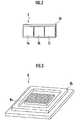
- FIG. 2 the overall view of the light source 5 is illustrated in FIG. 2 .
- the light source 5 is composed of three LEDs 5a to 5c, each having a 1 mm ⁇ 1 mm square shape (e.g., at a wavelength of 460 nm), and the LEDs are disposed in such a direction to assume the horizontal direction of the light distribution pattern. Further, the LEDs 5a to 5c are housed in an LED package 5d with a slight gap therebetween.
- Phosphor-containing resin is applied to the surface of the LEDs 5a to 5c so that blue light emitted from the LEDs 5a to 5c will be irradiated to the phosphor-containing resin to emit white light. Then, the white light is collected by the condenser lens 7.
- a phosphor plate may be placed to come into contact with the front face side of each of the LEDs 5a to 5c.
- one phosphor plate capable of covering all of the LEDs 5a to 5c may be placed on the front face side of the LEDs 5a to 5c.
- a diffuser plate for shaping light in a round (elliptical) form while controlling the diffusion angle can also be used instead of the phosphor plate to achieve the same effect.
- a phosphor plate to cover the light-emitting face is required separately in addition to the diffuser plate, where the phosphor plate is placed on the front face of each of the LEDs 5a to 5c, and the diffuser plate is placed in front of the phosphor plate.
- FIG. 3 An overall perspective view of the digital mirror 8 is illustrated in FIG. 3 .
- the digital mirror 8 is made up in such a manner that a mirror unit 8a (about 10 mm ⁇ 30 mm) with square mirror elements of several tens of ⁇ m long is arranged and housed in a mirror package 8b. Each mirror element can reflect incident light in two directions (e.g., +12° or -12°).
- the mirror elements when the mirror elements reflect the incident light in one direction, since the light travels in the direction of the projection lens 9, the light forms a light distribution pattern.
- the mirror elements reflect the incident light in the other direction, since the light deflects from the projection lens 9, the light forms a light shielding pattern that shields the light distribution pattern.
- the vehicle headlight device 1 can form various light distribution patterns in the irradiated area S.
- the light output from the light source 5 penetrates the phosphor-containing resin and enters the digital mirror 8 with some spread.
- the actuator control unit 14 finely controls the mirror elements, a determinate light distribution pattern is never blurred.
- the mirror unit 8a of the digital mirror 8 is equal in aspect ratio to the light source 5 (light-emitting face), forming a similarity shape. Since the light source 5 and the mirror unit 8a are similar in shape to each other, the light emitted from the light source 5 enters the mirror unit 8a while keeping the shape, and is projected to the irradiated area S. Thus, the vehicle headlight device 1 can form a light distribution pattern with a simple structure. Further, when the light emitted from the light source 5 enters the digital mirror 8, light deflecting from the area of the mirror unit 8a can be reduced, resulting in enhancing the light use efficiency.
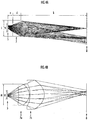
- FIG. 4A an optical system composed of the same light source 5, condenser lens 7, and digital mirror 8 as those of the optical system 2 (see FIG. 1 ) is illustrated in FIG. 4A .
- the light source 5, the condenser lens 7, and the digital mirror 8 (mirror unit 8a) are arranged in such a manner that the center axes of respective members are aligned with one another, distance between the light source 5 and the condenser lens 7 (rear end) is kept at distance a, and distance between the condenser lens 7 (lens unit) and the digital mirror 8 is kept at distance b. Further, a longitudinal width W of the light source 5 is set smaller than a diameter L of the condenser lens 7.
- the focal length of the condenser lens 7 is denoted as f
- the size of an image obtained by projecting the light emitted from the light source 5 to the digital mirror 8 becomes b/a times the light source 5 (the area s of the light-emitting face). Therefore, the irradiated area on the digital mirror 8 calculated from the distances a, b, and the area s in this example becomes sb/a.
- the condenser lens 7 is a thick convex lens with a thickness d and having a small convex portion on the side of the light source 5 as well.
- the condenser lens 7 is required to have a thickness enough to adjust the magnifying power b/a determined by the positions of the light source 5 and the digital mirror 8 without virtually changing the curvature of the lens convex surface. Since a thin lens with a thickness of about 2 mm to 4 mm cannot adjust the magnifying power b/a, a thick lens with a thickness of 17 mm is used in the embodiment.
- Dist % Y ⁇ y ⁇ y ⁇ ⁇ 100
- the distortion is a positive value to make the image (image height Y) projected to the digital mirror 8 becomes larger than in reality due to the distortion.
- Dist +10(%)
- the real image height Y 1.1 y'.
- the image projected to the digital mirror 8 becomes larger than the calculated irradiated area sb/a.
- the irradiated area on the digital mirror 8 is calculated to have a 42.0 mm ⁇ 42.0 mm square shape.
- the size of the light source 5 is changed to have a 7.6 mm ⁇ 7.6 mm square shape, as being reduced by about 10%, to allow the light from the light source 5 to fit in the irradiated area on the digital mirror 8 without waste.
- the light from the light source 5 has only to fit within the range of the mirror unit 8a of the digital mirror 8. Therefore, the size of the light source 5 (light-emitting face) is set smaller than a theoretical size in consideration of the positive-value distortion. Such an operation makes it easy for the vehicle headlight device 1 to fit the light from the light source 5 in the range of the mirror unit 8a without particularly changing the arrangement of the structural members.
- FIG. 4B An optical system composed of two or more condenser lenses 7a, 7b is illustrated in FIG. 4B . Even in this case, a longitudinal width W of the light source 5 is set smaller than a diameter M of the condenser lens 7a.
- the distortion may be a negative value.
- the image (image height Y) projected to the digital mirror 8 becomes smaller than in reality due to the distortion.
- the image projected to the digital mirror 8 becomes smaller than the calculated irradiated area sb/a.
- the size of the light source 5 (light-emitting face) is set larger than the theoretical size. This prevents the light from the light source 5 from becoming too small for the area of the mirror unit 8a when the light irradiates the mirror unit 8a.
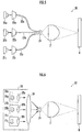
- a vehicle headlight device 20 having a light source composed of plural laser diodes (hereinafter called LDs) will be described. Note that the description of the same structural elements as those in the first embodiment is omitted.
- the light source of the vehicle headlight device 20 is composed of three blue LDs 21a to 21c ("light-emitting elements" in the present invention).
- Reflectors 22a to 22c each of which reflects and guides laser light to one end of each of multifibers to be described later, are provided for the blue LDs 21a to 21c, respectively.
- multifibers 23a to 23c (“optical fibers" in the present invention) are connected to the reflectors 22a to 22c, respectively.
- the multifibers 23a to 23c are bundled on the other end side, and the ends (light-emitting faces) are arranged on the front side of a phosphor plate 24.
- the laser light emitted from the blue LDs 21a to 21c is irradiated to the phosphor plate 24.
- the vehicle headlight device 20 can enhance the intensity of fluorescence excited in the phosphor plate 24. Further, the excitation light of the phosphor plate 24 is collected by the condenser lens 7 to enter the digital mirror 8 in the end. Such an optical system can realize a simple and small vehicle headlight device.
- a light source composed of three white LDs may be used.
- the white LD there is a structure in which the blue LD is covered with a phosphor. In this case, such a property that laser light of the blue LD is excited by the phosphor to become white is used.
- a diffuser plate can be used instead of the phosphor plate 24. Since the diffuser plate can form the laser light into a round (elliptical) shape with high optical transmittance, the laser light can enter the condenser lens 7 efficiently. Note that the other ends of the multifibers 23a to 23c may be bundled by a fiber bundle to guide the laser light directly to the condenser lens 7.
- the light-emitting elements of the light source may be a red LD, a green LD, and a blue LD (RGB laser).
- the diffuser plate instead of the phosphor plate 24 so that three RGB colors can be mixed efficiently.
- the LDs are used in the embodiment, but LEDs may also be used. In the case of a light source using one LD or LED, one multifiber is used.
- a vehicle headlight device 30 having a light source, composed of plural LDs, and a condenser lens will be described. Note that the same structural elements as those in the vehicle headlight device 20 of the second embodiment are given the same reference numerals to omit the description thereof.
- the light source of the vehicle headlight device 30 is composed of three blue LDs 21a to 21c housed inside light-collecting casings 31a to 31c, respectively.
- the inside of each of the light-collecting casings 31a to 31c is the same reflecting mirror surface as that of each reflector to reflect laser light emitted from each of the blue LDs 21a to 21c and guide the reflected light in the direction of each of condenser lenses 32a to 32c, respectively.
- the light-collecting casings 31 a to 31c are stored in a larger light-collecting casing 33.
- the inside of the light-collecting casing 33 is a reflecting mirror surface to reflect light emitted from the condenser lenses 32a to 32c and guide the reflected light in the direction of a larger condenser lens 34.
- a phosphor plate 24 is placed in front of the condenser lens 34.
- the light emitted from the condenser lens 34 is irradiated to the phosphor plate 24, and fluorescence is excited from the phosphor plate 24.
- the excitation light of the phosphor plate 24 is collected by the condenser lens 7 to enter the digital mirror 8 in the end.
- Such an optical system can also realize a simple and small vehicle headlight device.
- a light source composed of three white LDs may also be used.
- a diffuser plate can be used instead of the phosphor plate 24.
- light-collecting casings in which a red LD, a green LD, and a blue LD are housed respectively, may be placed inside a light-collecting casing capable of storing these light-collecting casings.
- a similar optical system can be constructed.
- One blue LD can also be used.
- the larger light-collecting casing 33 is unnecessary, that is, the blue LD has only to be arranged to make the laser light of the blue LD enter the phosphor plate 24 directly through the condenser lens of the light-collecting casing of the blue LD.
- the LDs are used in the embodiment, but LEDs may also be used.
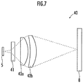
- a vehicle headlight device 40 having two or more condenser lenses will be described with reference to FIG. 7 . Note that the same structural elements as those in the vehicle headlight device 20 of the second embodiment are given the same reference numerals to omit the description thereof.
- a light source 5 of the vehicle headlight device 40 is composed of only one LED. Further, a first condenser lens 42a and a second condenser lens 42b are arranged in front of the light source 5. As described with reference to FIG. 4B , when two or more condenser lenses are arranged next to each other, the distortion may be a negative value. On this occasion, an image projected to a digital mirror becomes smaller than in reality due to the distortion.
- a plate glass 41 having a predetermine thickness is placed between the light source 5 and the first condenser lens 42a adjacent to the light source 5 to adjust the size of the image.
- light emitted from the light source 5 is refracted by the plate glass 41 and hence the angle of the light is widened, thus entering the first condenser lens 42a and the second condenser lens 42b.
- the LED light can expand the irradiation range on the digital mirror 8 without changing the size of the light source 5.
- the light source 5 may be composed of plurality of LEDs, or an LD may be used instead of the LED.
- the vehicle headlight device of each embodiment can adjust the size of an image to be projected to the digital mirror, light emitted from the light source (light-emitting face) enters the digital mirror without waste. This can lead to generating a light distribution pattern efficiently even when the device has a simple structure.
- the light source may be a large, arrayed type light source composed of a total of 15 LEDs each having a 0.5 mm ⁇ 0.5 mm square shape (in a 3 ⁇ 5 matrix).
- the wavelength of each LED can also be changed appropriately.
- the condenser lens 7 of the vehicle headlight device 1 is a thick convex lens having convex portions in the front and rear directions
- the present invention is not limited thereto.
- a condenser lens on which a glass having a high refractive index is mounted on one side (the side of the light source) may also be used.
- condenser lenses having high transmittance may be used instead of the reflectors 22a to 22c to collect and guide laser light from the blue LDs 21a to 21c to the multifibers 23a to 23c.
Landscapes
- Engineering & Computer Science (AREA)
- General Engineering & Computer Science (AREA)
- Physics & Mathematics (AREA)
- Optics & Photonics (AREA)
- Mathematical Physics (AREA)
- Microelectronics & Electronic Packaging (AREA)
- Mechanical Engineering (AREA)
- Non-Portable Lighting Devices Or Systems Thereof (AREA)
Applications Claiming Priority (1)
| Application Number | Priority Date | Filing Date | Title |
|---|---|---|---|
| JP2016048191A JP2017162760A (ja) | 2016-03-11 | 2016-03-11 | 車両用前照灯装置 |
Publications (1)
| Publication Number | Publication Date |
|---|---|
| EP3228929A1 true EP3228929A1 (de) | 2017-10-11 |
Family
ID=58054076
Family Applications (1)
| Application Number | Title | Priority Date | Filing Date |
|---|---|---|---|
| EP17156556.7A Withdrawn EP3228929A1 (de) | 2016-03-11 | 2017-02-16 | Fahrzeugscheinwerfervorrichtung |
Country Status (3)
| Country | Link |
|---|---|
| US (1) | US20170261173A1 (de) |
| EP (1) | EP3228929A1 (de) |
| JP (1) | JP2017162760A (de) |
Families Citing this family (9)
| Publication number | Priority date | Publication date | Assignee | Title |
|---|---|---|---|---|
| US10293691B2 (en) * | 2017-10-10 | 2019-05-21 | Denso International America, Inc. | Meter assembly |
| US10232763B1 (en) | 2017-11-27 | 2019-03-19 | Atieva, Inc. | Solid state adaptive headlight |
| ES2832877T3 (es) * | 2017-12-01 | 2021-06-11 | Marelli Automotive Lighting Italy Spa | Unidad de iluminación de automoción |
| JP2019212367A (ja) * | 2018-05-31 | 2019-12-12 | 株式会社小糸製作所 | 灯具ユニット |
| FR3106671B1 (fr) | 2019-12-20 | 2022-07-15 | Valeo Vision | Système de projection de faisceaux lumineux |
| KR102784598B1 (ko) * | 2019-12-27 | 2025-03-21 | 에스엘 주식회사 | 차량용 램프 |
| EP4321798A4 (de) * | 2021-04-09 | 2025-04-16 | Ichikoh Industries, Ltd. | Fahrzeugleuchte |
| US11971148B1 (en) | 2022-11-08 | 2024-04-30 | Atieva, Inc. | High contrast solid state adaptive headlight |
| WO2025214817A1 (en) * | 2024-04-12 | 2025-10-16 | Signify Holding B.V. | A laser lighting device |
Citations (8)
| Publication number | Priority date | Publication date | Assignee | Title |
|---|---|---|---|---|
| JPH0455578B2 (de) | 1986-06-30 | 1992-09-03 | Toyoda Gosei Kk | |
| US20050174771A1 (en) * | 2004-02-11 | 2005-08-11 | 3M Innovative Properties Company | Reshaping light source modules and illumination systems using the same |
| US20150285458A1 (en) * | 2014-04-08 | 2015-10-08 | Ford Global Technologies, Llc | Vehicle headlamp system |
| US20150345729A1 (en) * | 2014-06-03 | 2015-12-03 | Coretronic Corporation | Illumination apparatus for vehicle |
| US20150377446A1 (en) * | 2014-06-26 | 2015-12-31 | Texas Instruments Incorporated | Methods and Apparatus for Illumination with DMD and Laser Modulated Adaptive Beam Shaping |
| US20150377430A1 (en) * | 2014-06-26 | 2015-12-31 | Texas Instruments Incorporated | Hybrid Illumination for Headlamp |
| JP2016008043A (ja) | 2014-06-26 | 2016-01-18 | 中強光電股▲ふん▼有限公司 | 車両用照明装置 |
| DE102014013202B3 (de) * | 2014-09-06 | 2016-02-04 | Audi Ag | Scheinwerfer für einen Kraftwagen sowie ein Kraftwagen |
Family Cites Families (9)
| Publication number | Priority date | Publication date | Assignee | Title |
|---|---|---|---|---|
| JP4995748B2 (ja) * | 2008-01-29 | 2012-08-08 | 株式会社小糸製作所 | 車両用前照灯装置及び車両用前照灯装置の制御方法 |
| US8033697B2 (en) * | 2009-02-18 | 2011-10-11 | National Kaohsiung First University Of Science And Technology | Automotive headlight system and adaptive automotive headlight system with instant control and compensation |
| JP4991001B2 (ja) * | 2009-12-28 | 2012-08-01 | シャープ株式会社 | 照明装置 |
| US20110280033A1 (en) * | 2010-05-17 | 2011-11-17 | Sharp Kabushiki Kaisha | Light-emitting device, illumination device, and vehicle headlamp |
| US9816677B2 (en) * | 2010-10-29 | 2017-11-14 | Sharp Kabushiki Kaisha | Light emitting device, vehicle headlamp, illumination device, and laser element |
| JP5487077B2 (ja) * | 2010-10-29 | 2014-05-07 | シャープ株式会社 | 発光装置、車両用前照灯および照明装置 |
| JP5336564B2 (ja) * | 2010-10-29 | 2013-11-06 | シャープ株式会社 | 発光装置、照明装置、車両用前照灯および車両 |
| JP5758717B2 (ja) * | 2011-06-22 | 2015-08-05 | スタンレー電気株式会社 | 車両用照明装置 |
| KR101856362B1 (ko) * | 2016-09-30 | 2018-05-10 | 현대자동차주식회사 | 차량용 헤드램프 장치 |
-
2016
- 2016-03-11 JP JP2016048191A patent/JP2017162760A/ja active Pending
-
2017
- 2017-02-16 EP EP17156556.7A patent/EP3228929A1/de not_active Withdrawn
- 2017-02-16 US US15/434,860 patent/US20170261173A1/en not_active Abandoned
Patent Citations (8)
| Publication number | Priority date | Publication date | Assignee | Title |
|---|---|---|---|---|
| JPH0455578B2 (de) | 1986-06-30 | 1992-09-03 | Toyoda Gosei Kk | |
| US20050174771A1 (en) * | 2004-02-11 | 2005-08-11 | 3M Innovative Properties Company | Reshaping light source modules and illumination systems using the same |
| US20150285458A1 (en) * | 2014-04-08 | 2015-10-08 | Ford Global Technologies, Llc | Vehicle headlamp system |
| US20150345729A1 (en) * | 2014-06-03 | 2015-12-03 | Coretronic Corporation | Illumination apparatus for vehicle |
| US20150377446A1 (en) * | 2014-06-26 | 2015-12-31 | Texas Instruments Incorporated | Methods and Apparatus for Illumination with DMD and Laser Modulated Adaptive Beam Shaping |
| US20150377430A1 (en) * | 2014-06-26 | 2015-12-31 | Texas Instruments Incorporated | Hybrid Illumination for Headlamp |
| JP2016008043A (ja) | 2014-06-26 | 2016-01-18 | 中強光電股▲ふん▼有限公司 | 車両用照明装置 |
| DE102014013202B3 (de) * | 2014-09-06 | 2016-02-04 | Audi Ag | Scheinwerfer für einen Kraftwagen sowie ein Kraftwagen |
Non-Patent Citations (1)
| Title |
|---|
| ANONYMOUS: "Lens (optics) - From Wikipedia, the free encyclopedia", 18 October 2010 (2010-10-18), pages 1 - 6, XP055102319, Retrieved from the Internet <URL:https://en.wikipedia.org/w/index.php?title=Lens_%28optics%29&oldid=707436021> [retrieved on 20140214] * |
Also Published As
| Publication number | Publication date |
|---|---|
| US20170261173A1 (en) | 2017-09-14 |
| JP2017162760A (ja) | 2017-09-14 |
Similar Documents
| Publication | Publication Date | Title |
|---|---|---|
| EP3228929A1 (de) | Fahrzeugscheinwerfervorrichtung | |
| US9611996B2 (en) | Motor vehicle headlamp | |
| US11235700B2 (en) | Illumination device, in particular for a motor vehicle | |
| US9512972B2 (en) | Headlight system incorporating adaptive beam function | |
| CN113039387B (zh) | 用于车辆照明装置的发光模块 | |
| EP3447561B1 (de) | Head-up-anzeigevorrichtung | |
| EP1930651A1 (de) | Lichtquellenvorrichtung und Fahrzeugbeleuchtungsvorrichtung | |
| US20220120406A1 (en) | Lamp for vehicle | |
| KR20190033006A (ko) | 차량용 등기구 | |
| EP3196544A1 (de) | Fahrzeugscheinwerfervorrichtung | |
| US20150219300A1 (en) | Light source for head light and head light | |
| CN108302464B (zh) | 用于机动车辆的光学模块 | |
| JP7151190B2 (ja) | 車両用灯具 | |
| CN107850281A (zh) | 用于车辆大灯的激光照明装置 | |
| EP3680547A1 (de) | Leuchte für fahrzeuge | |
| KR100453040B1 (ko) | 콜리메이팅 렌즈, 콜리메이팅 시스템 및 이를 채용한 화상표시장치 | |
| JP5043597B2 (ja) | ダイレクトプロジェクション型照明用灯具 | |
| KR20220089942A (ko) | 차량용 램프 | |
| KR20170079355A (ko) | 발광 장치, 이 장치를 포함하는 광학 모듈, 및 이 모듈을 포함하는 차량 | |
| JP2020059377A (ja) | 光照射システム | |
| JP7186570B2 (ja) | 車両用灯具 | |
| CN105318281B (zh) | 用于前照灯的激光光学系统 | |
| EP1541921B1 (de) | Farbkorrigiertes Laserbeleuchtungssystem für Nachtsichtzwecke | |
| EP3712489A1 (de) | Fahrzeugleuchte | |
| EP3196545A1 (de) | Fahrzeuglampe |
Legal Events
| Date | Code | Title | Description |
|---|---|---|---|
| PUAI | Public reference made under article 153(3) epc to a published international application that has entered the european phase |
Free format text: ORIGINAL CODE: 0009012 |
|
| AK | Designated contracting states |
Kind code of ref document: A1 Designated state(s): AL AT BE BG CH CY CZ DE DK EE ES FI FR GB GR HR HU IE IS IT LI LT LU LV MC MK MT NL NO PL PT RO RS SE SI SK SM TR |
|
| AX | Request for extension of the european patent |
Extension state: BA ME |
|
| STAA | Information on the status of an ep patent application or granted ep patent |
Free format text: STATUS: THE APPLICATION IS DEEMED TO BE WITHDRAWN |
|
| 18D | Application deemed to be withdrawn |
Effective date: 20180412 |