EP3228919A1 - Füllverfahren und fülleinrichtung für mobile sauerstoffspeicher - Google Patents
Füllverfahren und fülleinrichtung für mobile sauerstoffspeicher Download PDFInfo
- Publication number
- EP3228919A1 EP3228919A1 EP17154338.2A EP17154338A EP3228919A1 EP 3228919 A1 EP3228919 A1 EP 3228919A1 EP 17154338 A EP17154338 A EP 17154338A EP 3228919 A1 EP3228919 A1 EP 3228919A1
- Authority
- EP
- European Patent Office
- Prior art keywords
- oxygen
- storage
- mobile
- pressure
- oxygen storage
- Prior art date
- Legal status (The legal status is an assumption and is not a legal conclusion. Google has not performed a legal analysis and makes no representation as to the accuracy of the status listed.)
- Granted
Links
Images



Classifications
-
- F—MECHANICAL ENGINEERING; LIGHTING; HEATING; WEAPONS; BLASTING
- F17—STORING OR DISTRIBUTING GASES OR LIQUIDS
- F17C—VESSELS FOR CONTAINING OR STORING COMPRESSED, LIQUEFIED OR SOLIDIFIED GASES; FIXED-CAPACITY GAS-HOLDERS; FILLING VESSELS WITH, OR DISCHARGING FROM VESSELS, COMPRESSED, LIQUEFIED, OR SOLIDIFIED GASES
- F17C7/00—Methods or apparatus for discharging liquefied, solidified, or compressed gases from pressure vessels, not covered by another subclass
-
- F—MECHANICAL ENGINEERING; LIGHTING; HEATING; WEAPONS; BLASTING
- F17—STORING OR DISTRIBUTING GASES OR LIQUIDS
- F17C—VESSELS FOR CONTAINING OR STORING COMPRESSED, LIQUEFIED OR SOLIDIFIED GASES; FIXED-CAPACITY GAS-HOLDERS; FILLING VESSELS WITH, OR DISCHARGING FROM VESSELS, COMPRESSED, LIQUEFIED, OR SOLIDIFIED GASES
- F17C2205/00—Vessel construction, in particular mounting arrangements, attachments or identifications means
- F17C2205/03—Fluid connections, filters, valves, closure means or other attachments
- F17C2205/0302—Fittings, valves, filters, or components in connection with the gas storage device
- F17C2205/0323—Valves
- F17C2205/0332—Safety valves or pressure relief valves
-
- F—MECHANICAL ENGINEERING; LIGHTING; HEATING; WEAPONS; BLASTING
- F17—STORING OR DISTRIBUTING GASES OR LIQUIDS
- F17C—VESSELS FOR CONTAINING OR STORING COMPRESSED, LIQUEFIED OR SOLIDIFIED GASES; FIXED-CAPACITY GAS-HOLDERS; FILLING VESSELS WITH, OR DISCHARGING FROM VESSELS, COMPRESSED, LIQUEFIED, OR SOLIDIFIED GASES
- F17C2221/00—Handled fluid, in particular type of fluid
- F17C2221/01—Pure fluids
- F17C2221/011—Oxygen
-
- F—MECHANICAL ENGINEERING; LIGHTING; HEATING; WEAPONS; BLASTING
- F17—STORING OR DISTRIBUTING GASES OR LIQUIDS
- F17C—VESSELS FOR CONTAINING OR STORING COMPRESSED, LIQUEFIED OR SOLIDIFIED GASES; FIXED-CAPACITY GAS-HOLDERS; FILLING VESSELS WITH, OR DISCHARGING FROM VESSELS, COMPRESSED, LIQUEFIED, OR SOLIDIFIED GASES
- F17C2223/00—Handled fluid before transfer, i.e. state of fluid when stored in the vessel or before transfer from the vessel
- F17C2223/03—Handled fluid before transfer, i.e. state of fluid when stored in the vessel or before transfer from the vessel characterised by the pressure level
- F17C2223/036—Very high pressure (>80 bar)
-
- F—MECHANICAL ENGINEERING; LIGHTING; HEATING; WEAPONS; BLASTING
- F17—STORING OR DISTRIBUTING GASES OR LIQUIDS
- F17C—VESSELS FOR CONTAINING OR STORING COMPRESSED, LIQUEFIED OR SOLIDIFIED GASES; FIXED-CAPACITY GAS-HOLDERS; FILLING VESSELS WITH, OR DISCHARGING FROM VESSELS, COMPRESSED, LIQUEFIED, OR SOLIDIFIED GASES
- F17C2250/00—Accessories; Control means; Indicating, measuring or monitoring of parameters
- F17C2250/04—Indicating or measuring of parameters as input values
- F17C2250/0404—Parameters indicated or measured
- F17C2250/0408—Level of content in the vessel
-
- F—MECHANICAL ENGINEERING; LIGHTING; HEATING; WEAPONS; BLASTING
- F17—STORING OR DISTRIBUTING GASES OR LIQUIDS
- F17C—VESSELS FOR CONTAINING OR STORING COMPRESSED, LIQUEFIED OR SOLIDIFIED GASES; FIXED-CAPACITY GAS-HOLDERS; FILLING VESSELS WITH, OR DISCHARGING FROM VESSELS, COMPRESSED, LIQUEFIED, OR SOLIDIFIED GASES
- F17C2250/00—Accessories; Control means; Indicating, measuring or monitoring of parameters
- F17C2250/04—Indicating or measuring of parameters as input values
- F17C2250/0404—Parameters indicated or measured
- F17C2250/043—Pressure
-
- F—MECHANICAL ENGINEERING; LIGHTING; HEATING; WEAPONS; BLASTING
- F17—STORING OR DISTRIBUTING GASES OR LIQUIDS
- F17C—VESSELS FOR CONTAINING OR STORING COMPRESSED, LIQUEFIED OR SOLIDIFIED GASES; FIXED-CAPACITY GAS-HOLDERS; FILLING VESSELS WITH, OR DISCHARGING FROM VESSELS, COMPRESSED, LIQUEFIED, OR SOLIDIFIED GASES
- F17C2260/00—Purposes of gas storage and gas handling
- F17C2260/04—Reducing risks and environmental impact
-
- F—MECHANICAL ENGINEERING; LIGHTING; HEATING; WEAPONS; BLASTING
- F17—STORING OR DISTRIBUTING GASES OR LIQUIDS
- F17C—VESSELS FOR CONTAINING OR STORING COMPRESSED, LIQUEFIED OR SOLIDIFIED GASES; FIXED-CAPACITY GAS-HOLDERS; FILLING VESSELS WITH, OR DISCHARGING FROM VESSELS, COMPRESSED, LIQUEFIED, OR SOLIDIFIED GASES
- F17C2270/00—Applications
- F17C2270/02—Applications for medical applications
- F17C2270/025—Breathing
Definitions
- the invention relates to a filling method and a filling device for mobile oxygen storage, comprising at least one mobile oxygen supply for vehicles and at least one coupling means for establishing an operative connection between the filling device and an oxygen storage device for a support device
- drugs of various kinds are used in a large number of different situations in order to alleviate or eliminate acute and chronic symptoms caused by diseases, harmful external influences and accident-related damage. Even in emergency situations, drugs are used to prevent, for example, imminent failure of the vital functions of an accident victim or disease-related collapse of persons.
- the respiratory air or the required respiratory air volume flow must be enriched with oxygen in order to increase the oxygen concentration to the medically required level increase.
- Oxygenation is typically achieved by delivery of higher or higher concentration oxygen admixed with the air provided by the ventilator to produce the oxygen-enriched breathing air.
- either storage media for oxygen storage or devices for oxygen concentration are usually used.
- suitable devices for oxygen concentration may also be an integral part of the respirator.
- oxygen In order to make oxygen available, in particular during the revival, even in these cases, oxygen must be transported in a storage medium to the scene of the accident. These oxygen storage media must be pressurized to about 200 bar in order to realize both the size of the storage medium and the amount of oxygen to be transported and thus the operating time in a practical range.
- Standard carrying devices include a receiving space and attachment means for a respirator and a high pressure oxygen cylinder coupled to the ventilator which must be previously filled with pressurized oxygen. Carrying devices of this type realize the emergency ventilation by prefilled oxygen cylinders, which must be replaced after emptying.
- Another disadvantage is that practically not always a complete emptying of the oxygen storage bottles of the carrying device is possible and remain unused residual oxygen content in the storage medium. This procedure is necessary because some residual oxygen volume in the reservoir is required to ensure mobile service in use. This requirement can only be met if minimum residual volumes are not undercut.
- connection technique of the oxygen storage bottle with the carrying device Another disadvantage often results from the connection technique of the oxygen storage bottle with the carrying device. Such a connection technique is exposed due to the often required bottle exchange increased wear and has a limited life.
- the invention proposes a device and a method for filling a mobile oxygen storage in a carrying device.
- the invention recognizes that the abovementioned disadvantages can be at least partially reduced by the fact that the oxygen storage device can be filled or refilled to supply the emergency ventilation device while it is being held in the carrying device. In this way, the replacement of the oxygen storage after its emptying or below the required residual oxygen level is obsolete.
- the invention provides that the carrying device with the recorded oxygen storage in such a design and constructively to condition that filling or refilling of the support device oxygen storage in the ambulance or ambulance is feasible.
- the vehicle In order to be able to provide these functions in an integral manner, in addition to the design of the carrying device, the vehicle must also be designed in a corresponding manner and have an oxygen supply.
- the or commonly used in ambulances or ambulance vehicles mounts for the emergency breathing apparatus with oxygen storage comprehensive carrying device modified and functionally expanded such that an operative connection by coupling means of the carrying device with the vehicle in addition to the actual mechanical support simultaneously also supports the introduction of oxygen gas for filling or refilling the oxygen storage in the carrying device.
- This operative connection with its at least one mechanical and an oxygen-conducting component comprehensive function must be at least temporarily feasible, i.
- the coupling must be detachable in order to be able to use the emergency ventilator with the carrying device outside the vehicle as well.
- the teaching of the invention comprises at least a mobile oxygen supply for vehicles and coupling means for temporary support and oxygen supply in a at least one oxygen storage comprehensive carrying device.
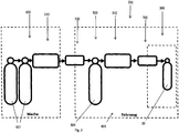
- FIG. 1 shows a schematic representation of a first embodiment of the filling device for mobile oxygen storage (200), comprising at least one mobile oxygen supply (500) for vehicles (400) and a carrying device (300) with at least one oxygen storage (30) for the enrichment of breathing gas of an emergency ventilator with Oxygen.
- the mobile oxygen supply (500) has at least one oxygen reservoir (501). It can be supplemented by a modifier (510).
- the mobile oxygen supply (500) for vehicles (400) is brought into an at least temporary operative connection by coupling means (700) with the carrying device (300) such that the oxygen storage device (300) and the oxygen storage device (501) are connected between the oxygen storage device (30) mobile oxygen supply (500) oxygen gas can flow.
- the oxygen reservoirs (30) of the carriers (300) are often designed as high pressure accumulators with a storage pressure of about 200 bar and a storage volume of about 2 liters. In order to be able to fill or top up these oxygen reservoirs, gas volume flows of approx. 20 liters per minute have proven successful.
- the oxygen storage (501) of the mobile oxygen supply (500) with a storage pressure of about 200 bar and a storage volume of about 10 liters provides good utilization results.
- the oxygen storage (30) in the support device (300) with oxygen gas from the mobile oxygen storage (501) can be filled or refilled, the For this required active compound produced by coupling agent (700).
- a high pressure suitable coupling which supports volume gas flows of up to 20 liters per minute and possibly also higher.
- the coupling may have its own latch for temporarily fixing the operative connection situation or a mechanical component couples the carrier device (300) and the oxygen supply (500) with both a holding and a functional connection function.
- the mobile oxygen supply (500) be supplemented by at least one modifier (510).
- the gas volume flows can assume inadmissibly high values, in particular at the beginning of the filling process, which can reach up to the speed of sound. Also, a high pressure drop when opening the gas supply can generate a pressure wave within the feed line, the energy of which can lead to component destruction. If this situation exists, the modifier (510) is formed at least from a volume flow limiter (512) which primarily comprises a throttle.
- modifier (510) may be required if a pressure increase needs to be realized. This is the case when the pressure in the oxygen storage (501) of the mobile oxygen supply (500) falls below the actual pressure or the target pressure to be achieved in the oxygen reservoir (30) of the support device (300).
- the modifier (510) is constructed from at least one pressure adjuster (511).
- the pressure adjuster (511) is constructed in this case as a pressure booster in the form of a pressure booster, which is primarily capable of increasing the pressure of any pressure less than 200 bar to the filling pressure of the oxygen reservoir (30) of the support device (300) of 200 bar to increase.
- the modifier (510) Due to the fact that, depending on the situation, either a pressure gradient or pressure pari must be present or an increase in pressure must be realized, it is possible for the modifier (510) to have at least one volume flow limiter (512) and one pressure phaser (511). Depending on the pressure and / or volumetric flow situation, it may further be necessary to switch at least two modifiers (510) in parallel or in series.
- coupling means (700) are provided in the form of a coupling (701) for high-pressure applications, either via a own locking for fixing the position or has been temporarily fixed by suitable locking between carrying system (300) and vehicle (400).
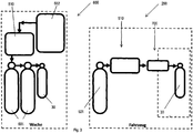
- FIG. 2 comprises the schematic representation of the first embodiment of the filling device for mobile oxygen storage (200) with functional extension of the mobile oxygen supply for vehicles (500) in the scope of an oxygen depot (600).
- This oxygen depot (600) located, for example, in a watch is used for the temporary (re) charging of the mobile oxygen supply (500).
- the oxygen reservoir (600) has at least one oxygen storage reservoir (601). It can be supplemented by a modifier (510).
- the oxygen depot (600) is connected by means of coupling (700) with the mobile Bringing oxygen supply (500) for vehicles (400) into an at least temporary operative connection such that oxygen gas can flow between the oxygen reservoir (600) and the mobile oxygen supply (500).
- the mobile oxygen depot (600) at least one modifier (510) be added.
- the gas volume flows in particular at the beginning of the filling process, can assume inadmissibly high values, which can reach up to the speed of sound. Also, a high pressure gradient when opening the gas supply, a pressure wave within the feed line entrain, whose energy can cause component destruction. If this situation exists, the modifier (510) is formed at least from a volume flow limiter (512) which primarily comprises a throttle.
- modifier (510) may be required if a pressure increase needs to be realized. This is the case when the pressure in the oxygen storage reservoir (601) of the oxygen reservoir (600) falls below the actual pressure or the target pressure to be reached in the oxygen reservoir (501) of the mobile oxygen supply (500). In this case, in order to be able to introduce the oxygen gas from the oxygen storage reservoir (601) of the oxygen reservoir (600) into the oxygen reservoir (501) of the mobile oxygen supply (500), the modifier (510) is made up of at least one pressure regulator (511).
- the pressure adjuster (511) is constructed in this case as a pressure booster in the form of a pressure booster, which is substantially capable of increasing the pressure from any pressure lower than 200 bar to the filling pressure of the oxygen storage (501) of the mobile oxygen supply (500) of 200 bar.
- the modifier (510) Due to the fact that, depending on the situation, either a pressure gradient or pressure pari must be present or an increase in pressure must be realized, it is possible for the modifier (510) to have at least one volume flow limiter (512) and one pressure phaser (511). Depending on the pressure and / or volume flow situation, it may further be necessary to switch at least two modifiers (510) in parallel or in series.
- coupling means (700) in the form of a coupling (701) are provided for high pressure applications via their own latching means Position fixation features.
- FIG. 3 shows the schematic representation of the filling device for mobile oxygen storage (200) with a functionally decoupled oxygen depot (600), which is installed for example in a guard or a control center.
- the oxygen reservoir (600) is designed such that at least one oxygen storage reservoir (601) and / or at least one oxygen reservoir (30) can be filled via, for example, an oxygen concentrator (602).
- at least one modifier (510) in the form of a pressure regulator (511) or pressure booster can interpose the oxygen volume flow offered by the oxygen concentrator at about 5 liters per minute up to a pressure of up to 200 bar increased.
- the respective storage volumes of the oxygen storage reservoirs (601) and the oxygen reservoirs (501) can be up to 10 liters, the volumes of the oxygen storage device (30) of the carrying device are often in the order of 2 liters.
- the storage pressures can be up to 200 bar oxygen gas pressure in all cases.
- FIG. 4 forms the schematic representation of the filling device for mobile oxygen storage (200) with an oxygen depot (600) in functional operative connection.
- the oxygen depot (600) in scope of realization as in the explanation too FIG. 3 is functionally coupled analogous to the procedure for the active compound according to the description FIG. 2 ,
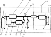
- FIG. 5 shows the schematic representation of the filling device for mobile oxygen storage (200) with an optionally integrable security system (800) to reduce a potential hazard in connection with the handling or a component failure of the high-pressure elements.
- the invention provides for the carrying system (300) to be locked within a receptacle in the vehicle (400), so that the coupling point (700) and the oxygen pressure system are hermetically sealed.
- the non-return valve (32) which is preferably implemented in the accumulator (31) of the oxygen accumulator (30) or as a separate component, ensures that no oxygen from the oxygen accumulator (30) in the direction of the coupling means also in the case of a pressure gradient for mobile oxygen supply (500) (700) can flow.
- Throttle (504) limits the flow of oxygen to a bypass valve (506) downstream of the check valve (505), while the check valve (505) prevents oxygen gas return to the pressure reducer (503) in the event that a pressure gradient in the form of a rise Oxygen storage (30) is present.
- a combination component may also be used.
- the pressure reducer (503) is to be used for further oxygen tapping points in the vehicle (400).
- a pressure reducer (503) is provided which reduces an applied pressure of up to 200-250 bar to an underlying pressure, for example up to 5 bar.
- the coupling means (700) and / or lines In order to check the tightness of the coupling means (700) and / or lines, it is provided first to apply oxygen gas into the supply line with a reduced pressure of less than 200 bar, for example 5 bar, set by the pressure reducer (503) and via the bypass valve (506). For the test, it is sufficient to initiate a short pressure surge so that the bypass valve (506) only has to be open for a short time. On the basis of a designated pressure sensor (507), the tightness property of the coupling means (700) and lines can be tested. Hermetically sealed situation exists when no or no appreciable pressure drop is measured in a unit of time.
- the modifier (510) designed as a pressure regulator (511) can be activated for the purpose of increasing the pressure, in particular to the filling level of the oxygen reservoir (30) of up to 200 bar.
- the pressure regulator (511) is limited to a volume flow rate of up to 20 liters per minute, so that in the event of a component or line failure, a risk to persons in the vicinity or in the vehicle is reduced.
- the line and the coupling means (700) are vented against the environment via a switchable valve (508).
- the coupling means (700) in the form of couplings (701) are designed such that a lock with hermetic tightness is given when an internal high pressure greater than 20 bar is applied.
- the carrying device (300) is temporarily fixed inseparably with or in the vehicle (400) after latching of the coupling means (700), which offers an additional safety factor.
- a switch may be provided on a handle of the carrying device (300), so that when the handle is grasped by an operator, a switch-off of the pressure adjuster (511) and venting via the valve (508) are initiated. In this way, the carrying device (300) can be decoupled in fractions of a second and made ready for use.
- FIG. 6 2 illustrates the schematic illustration of the filling device for mobile oxygen storage devices 200 with an optionally integrable safety system 800 in a second variant, in which a second bypass, parallel to the modifier 510, consists of a flow limiting device 512 with a bypass valve 506. is used.
- This volume flow limiting bypass can be situation-dependent and additive or alternative to the devices of the security system according to FIG. 5 be switched on.
- An oxygen volume flow limitation or an oxygen volume flow reduction via the volume flow limiter (512) may be useful if the situation prevails that the pressure in the oxygen storage (501) of the mobile oxygen supply (500) the actual pressure or the target pressure to be reached in the oxygen storage ( 30) of the carrier device (300) so that it can be filled or replenished with oxygen gas from the mobile oxygen reservoir (500) at least partially and without further pressure-modifying devices.
- the gas volume flows can assume inadmissibly high values, in particular at the beginning of the filling process, which can reach up to the speed of sound. Also, a high pressure gradient when opening the gas supply cause a pressure wave within the supply, the energy can cause component destruction. If this situation exists, the volumetric flow limiter (512) is switched via the circuit of the bypass valve (506) of the volumetric flow bypass. Preferably, the volume flow limiter (512) is designed to support volume flows of about 20 liters per minute.
- the security system (800) is at least partially formed of elements that are constituents of the mobile oxygen supply (500) and / or the carrying device (300) and / or the coupling means (700).
- the safety system (800) is formed from at least one oxygen gas feed train and at least one bypass train.
- the Sauerstoffgaszu Materialsstrang the safety system (800) at least a first modifier (510) and / or a pressure sensor (507) and / or coupling means (700).
- the oxygen gas feed train of the safety system (800) has at least one second modifier (510).
- the Sauerstoffgaszu Kunststoffstrang the safety system (800) by at least a first and a second check valve (505, 32) is supplemented.
- the oxygen gas supply line of the safety system (800) has at least one first valve (508) which assists the duct ventilation against the environment.
- the first bypass leg of the safety system (800) has at least one pressure reducer (503) and / or a throttle (504) and / or a check valve (505).
- the safety system (800) comprises a second bypass train comprising a volume flow restriction (512) and a bypass valve (506).
- the first and / or the second bypass branch of the security system (800) can be switched by a bypass valve (506) in a parallel manner to the oxygen supply line.
- a bypass valve 506
- the filling device for mobile oxygen storage (200) by an upstream oxygen depot (600) can be supplemented.
- the oxygen depot (600) can be coupled at least temporarily by coupling means (700) and an optional modifier (510) into an operative connection to the filling device for mobile oxygen storage (200), so that at least one oxygen storage (501, 30) can be filled with oxygen gas.
- the oxygen depot (600) has at least one oxygen storage reservoir (601).
- the oxygen depot (600) has at least one oxygen concentrator (602) and at least one modifier (510) so that the at least one oxygen storage reservoir (601) can be filled with high pressure oxygen gas.
- the at least one oxygen storage reservoir (601) is identical to an oxygen storage device (501, 30).
- the modifier (510) is a pressure phaser (511) and / or a volumetric flow limiter (512).
- the optional switching of a first bypass branch to the oxygen gas supply line occurs at least temporarily when there is a pressure gradient situation such that the pressure in the oxygen storage (501) of the mobile oxygen supply (500) is the actual pressure or to be reached Target pressure in the oxygen storage (30) of the support device (300) exceeds by more than 30%.
- the optional switching of a first bypass branch to the oxygen gas supply line occurs at least temporarily when there is a pressure gradient situation such that the pressure in the oxygen storage (501) of the mobile oxygen supply (500) is the actual pressure or to be reached Target pressure in the oxygen storage (30) of the support device (300) exceeds by more than 30%.
- the optional switching of a second bypass branch to the oxygen gas supply line occurs at least temporarily when there is a pressure gradient situation such that the pressure in the oxygen storage (501) of the mobile oxygen supply (500) is the actual pressure or to be reached Target pressure in the oxygen reservoir (30) of the support device (300) exceeds by more than 50%.
Landscapes
- Engineering & Computer Science (AREA)
- Mechanical Engineering (AREA)
- General Engineering & Computer Science (AREA)
- Filling Or Discharging Of Gas Storage Vessels (AREA)
Abstract
Description
- Die Erfindung betrifft ein Füllverfahren sowie eine Fülleinrichtung für mobile Sauerstoffspeicher, aufweisend wenigstens eine mobile Sauerstoffzufuhr für Fahrzeuge und wenigstens ein Kopplungsmittel zur Herstellung einer Wirkverbindung zwischen der Fülleinrichtung und einem Sauerstoffspeicher für eine Tragvorrichtung
- In der modernen Medizin werden in einer Vielzahl unterschiedlicher Situationen Medikamente verschiedenster Art eingesetzt, um akute und chronische Symptome, verursacht durch Krankheiten, schädliche äußere Einwirkungen und unfallbedingte Schäden zu lindern oder zu beseitigen. Auch in Notfallsituationen werden Medikamente eingesetzt, um beispielsweise drohendes Versagen der Vitalfunktionen eines Unfallopfers oder krankheitsbedingtes Kollabieren von Personen zu verhindern.
- In Notfallsituationen, insbesondere bei ambulanten Erstversorgungen von Patienten, ist es häufig erforderlich, dass Sauerstoff als Medikament über eine Notfallbeatmung verabreicht wird. Um diese mit Sauerstoff angereicherte Atemluft dem Patienten vor Ort zuführen zu können, werden mobile und ggfs. auch tragbare, in der Regel pneumatisch arbeitenden Beatmungsgeräte beispielsweise in Rettungsfahrzeugen oder Notarztwagen mitgeführt, um an einem Notfallort verfügbar zu sein.
- Um die sauerstoffangereicherte Atemluft durch das Beatmungsgerät, das häufig auch als Respirator bezeichnet wird, dem Patienten zur Verfügung stellen zu können, muss die Atemluft, beziehungsweise der benötigte Atemluftvolumenstrom, mit Sauerstoff angereichert werden, um auf diese Weise die Sauerstoffkonzentration auf das medizinisch erforderliche Maß zu erhöhen.
- Die Sauerstoffanreicherung wird üblicherweise durch Zuführung von höher- oder hochkonzentriertem Sauerstoff erreicht, die der durch das Beatmungsgerät bereitgestellten Luft beigemischt wird, um auf diese Weise die sauerstoffangereicherte Atemluft zu erzeugen. Um die Zuführung von höher- oder hochkonzentriertem Sauerstoff zu realisieren, werden üblicherweise entweder Speichermedien zur Sauerstoffbevorratung oder Vorrichtungen zur Sauerstoffkonzentration eingesetzt. Alternativ zur Sauerstoffzuführung zum Beatmungsgerät können auch geeignete Vorrichtungen zur Sauerstoffkonzentration integrativer Bestandteil des Beatmungsgerätes sein.
- Während bei stationären Beatmungsgeräten, beispielsweise im Einsatzbereich der Intensivmedizin, alle zuvor genannten Formen zur Bereitstellung von sauerstoffangereicherter Atemluft Anwendung finden, ergeben sich bei instationär und damit mobil verwendeten Beatmungsgeräten mit dem Kriterium der Mobilität insbesondere von Notfallbeatmungsgeräten besondere Anforderungen und Probleme.
- Viele der mobilen Sauerstoffversorungslösungen für instationäre Beatmungsgeräte sehen die Bereitstellung dieses Medikamentes in Form von Speichermedien vor, vorzugsweise in Flaschenform und meist als Druck- oder Hochdruckflaschen. Die Verfügbarkeit von höher- und hochkonzentriertem Sauerstoff in Flaschenspeichermedien ist über die Ländergrenzen hinweg weit verbreitet, aber nicht überall lückenlos verfügbar. Je nach Region oder im Katastrophenfall ist die Flaschenversorgung nicht gesichert, sodass gespeicherter Sauerstoff nicht uneingeschränkt zur Verfügung steht.
- Um Sauerstoff, insbesondere bei der Wiederbelebung, auch in diesen Fällen verfügbar zu machen, muss Sauerstoff in einem Speichermedium zum Unfallort transportiert werden. Diese Sauerstoffspeichermedien müssen auf ca. 200 bar druckbeaufschlagt werden, um sowohl die Größe des Speichermediums als auch die zu transportierende Sauerstoffmenge und damit die Betriebsdauer in einem praktikablen Bereich zu realisieren.
- Übliche Tragevorrichtungen verfügen über einen Aufnahmeraum und Befestigungseinrichtungen für ein Beatmungsgerät und eine mit dem Beatmungsgerät gekoppelte Sauerstoffhochdruckflasche, die zuvor mit druckbeaufschlagtem Sauerstoff gefüllt werden muss. Tragevorrichtungen dieser Art realisieren die Notfallbeatmung durch vorgefüllte Sauerstoffflaschen, die nach Entleerung gewechselt werden müssen.
- Diese Praxis ist mit einer Reihe von Nachteilen verbunden. Das Wechseln der entleerten Sauerstoffspeicherflaschen der Tragevorrichtung gegen gefüllte Flaschen ist häufig aufwändig. Darüber hinaus muss der Füllzustand der Sauerstoffspeicherflasche in der Tragevorrichtung zumindest regelmäßig kontrolliert werden.
- Weiterhin nachteilig ist, dass praktisch nicht immer eine vollständige Entleerung der Sauerstoffspeicherflaschen der Tragevorrichtung möglich ist und dadurch Sauerstoff-Restgehalte in dem Speichermedium ungenutzt bleiben. Diese Vorgehensweise ist erforderlich, da ein gewisses Rest-Sauerstoffvolumina im Speicher erforderlich ist, um die mobile Versorgung im Einsatz zu gewährleisten. Dieser Anforderung kann nur entsprochen werden, wenn Mindest-Restvolumina nicht unterschritten sind.
- Ein weiterer Nachteil ergibt sich häufig durch die Verbindungstechnik der Sauerstoffspeicherflasche mit der Tragevorrichtung. Eine derartige Verbindungstechnik ist infolge des häufig erforderlichen Flaschentausches erhöhtem Verschleiß ausgesetzt und verfügt über eine nur begrenzte Lebensdauer.
- Es ist daher Aufgabe der Erfindung, eine Sauerstoffzufuhr für instationäre Beatmungsgeräte bereitzustellen, die insbesondere die mobile Sauerstoffversorgung dieser Geräte innerhalb und/oder außerhalb der Reichweite von Fahrzeugen und bei gleichzeitiger Vereinfachung der Handhabung unterstützt.
- Zur Lösung dieser Aufgabe schlägt die Erfindung eine Vorrichtung und ein Verfahren zum Befüllen eines mobilen Sauerstoffspeichers in einer Tragevorrichtung vor.
- Grundsätzlich erkennt die Erfindung, dass die zuvor genannten Nachteile wenigstens teilweise reduzierbar sind dadurch, dass der Sauerstoffspeicher zur Versorgung des Notfallbeatmungsgerätes befüllbar bzw. nachfüllbar ist, während er in der Tragevorrichtung gehaltert wird. Auf diese Weise ist das Auswechseln des Sauerstoffspeichers nach dessen Entleerung oder Unterschreitung des erforderlichen Restsauerstoffniveaus obsolet.
- Die Erfindung sieht vor, das die Tragevorrichtung mit dem aufgenommenen Sauerstoffspeicher derart auszugestalten und konstruktiv zu konditionieren, dass ein Befüllen bzw. Nachfüllen des Tragevorrichtung-Sauerstoffspeichers in dem Rettungsfahrzeug oder Notarztwagen realisierbar ist.
- Durch die Integration der Halterungs- und Kopplungsfunktionen in die Tragevorrichtung ist es möglich, die Tragevorrichtung und damit die aufgenommene Sauerstoffflasche durch die lösbare Festlegung in der Wandhaltung des Rettungsfahrzeugs direkt und ohne die Flasche aus der Tragevorrichtung zu entfernen und von dem Beatmungsgerät entkoppeln, über eine Vorrichtung zur Sauerstoffversorgung mit druckbeaufschlagtem Sauerstoffgas zu befüllen.
- Um diese Funktionen in integraler Art bereitstellen zu können, muss neben der Ausgestaltung der Tragevorrichtung auch das Fahrzeug in korrespondierender Weise ausgebildet sein und über eine Sauerstoffzufuhr verfügen. Dazu werden das oder die üblicherweise in Rettungsfahrzeugen oder Notarztwagen verwendeten Halterungen für das Notfallbeatmungsgerät mit Sauerstoffspeicher umfassende Tragevorrichtung modifiziert und funktionell erweitert derart, dass eine Wirkverbindung durch Kopplungsmittel der Tragevorrichtung mit dem Fahrzeug neben der eigentlichen mechanischen Halterung gleichzeitig auch die Einleitung von Sauerstoffgas zur Befüllung oder Nachfüllung des Sauerstoffspeichers im Tragevorrichtung unterstützt.
- Diese Wirkverbindung mit ihrer wenigstens einen mechanischen und einen sauerstoffleitenden Komponente umfassenden Funktion muss zumindest temporär realisierbar sein, d.h. die Kopplung muss lösbar sein, um das Notfallbeatmungsgerät mit der Tragevorrichtung auch ausserhalb des Fahrzeugs einsetzen zu können.
- Basierend auf diesen Punkten des der Erfindung zugrundeliegenden Lastenheftes umfasst die erfindungsgemäße Lehre wenigstens eine mobile Sauerstoffzufuhr für Fahrzeuge sowie Kopplungsmittel zur temporären Halterung und Sauerstoffzuführung in eine wenigstens einen Sauerstoffspeicher umfassende Tragevorrichtung.
- Verschiedene Ausführungsbeispiele und Ausgestaltungen der Erfindung sind in den nachfolgenden Figuren abgebildet. Es zeigen
- Figur 1:
- in einer schematischen Darstellung ein erstes Ausführungsbeispiel der Fülleinrichtung für mobile Sauerstoffspeicher (200) aufweisend wenigstens eine mobile Sauerstoffzufuhr (500) für Fahrzeuge (400) und eine Tragevorrichtung (300) mit wenigstens einem Sauerstoffspeicher (30) zur Anreicherung von Atemgas eines Notfallbeatmungsgerätes mit Sauerstoff und
- Figur 2:
- die schematische Darstellung des erstes Ausführungsbeispiels der Fülleinrichtung für mobile Sauerstoffspeicher (200) mit funktioneller Erweiterung der mobilen Sauerstoffzufuhr für Fahrzeuge (500) im Umfang eines Sauerstoffdepots (600) und
- Figur 3:
- die schematische Darstellung der Fülleinrichtung für mobile Sauerstoffspeicher (200) mit einem funktional entkoppelten Sauerstoffdepot (600) und
- Figur 4:
- die schematische Darstellung der Fülleinrichtung für mobile Sauerstoffspeicher (200) mit einem Sauerstoffdepot (600) in funktionaler Kopplung sowie
- Figur 5:
- die schematische Darstellung der Fülleinrichtung für mobile Sauerstoffspeicher (200) mit einem optional integrierbaren Sicherheitssystem (800) und
- Figur 6:
- die schematische Darstellung der Fülleinrichtung für mobile Sauerstoffspeicher (200) mit einem optional integrierbaren Sicherheitssystem (800) in einer zweiten Ausführungsvariante.
-
Figur 1 zeigt in einer schematischen Darstellung ein erstes Ausführungsbeispiel der Fülleinrichtung für mobile Sauerstoffspeicher (200), aufweisend wenigstens eine mobile Sauerstoffzufuhr (500) für Fahrzeuge (400) und eine Tragevorrichtung (300) mit wenigstens einem Sauerstoffspeicher (30) zur Anreicherung von Atemgas eines Notfallbeatmungsgerätes mit Sauerstoff. Die mobile Sauerstoffzufuhr (500) weist zumindest einen Sauerstoffspeicher (501) auf. Ergänzt werden kann er durch einen Modifikator (510). Die mobile Sauerstoffzufuhr (500) für Fahrzeuge (400) wird durch Kopplungsmittel (700) mit der Tragevorrichtung (300) derart in eine wenigstens temporäre Wirkverbindung gebracht, sodass zwischen dem Sauerstoffspeicher (30) der Tragevorrichtung (300) und dem Sauerstoffspeicher (501) der mobilen Sauerstoffzufuhr (500) Sauerstoffgas strömen kann. - Um ein praktikables Größen-Speichervolumenverhältnis zu unterstützen, sind die Sauerstoffspeicher (30) der Tragevorrichtungen (300) häufig als Hochdruckspeicher mit einem Speicherdruck von ca. 200 bar und einem Speichervolumen von ca. 2 Liter konzipiert. Um diese Sauerstoffspeicher befüllen beziehungsweise nachfüllen zu können haben sich Gasvolumenströme von ca. 20 Liter pro Minute bewährt. Gleichfalls hat sich gezeigt, dass der Sauerstoffspeicher (501) der mobilen Sauerstoffzufuhr (500) mit einem Speicherdruck von ca. 200 bar und einem Speichervolumen von ca. 10 Liter gute Nutzungsergebnisse liefert.
Damit der Sauerstoffspeicher (30) in der Tragevorrichtung (300) mit Sauerstoffgas aus dem mobilen Sauerstoffspeicher (501) befüllt oder nachgefüllt werden kann, wird die dazu erforderliche Wirkverbindung durch Kopplungsmittel (700) hergestellt. Erfindungsgemäß ist vorgesehen, eine hochdrucktaugliche Kupplung einzusetzen, die Volumengasströme von bis zu 20 Litern pro Minute und gegebenenfalls auch höher unterstützt. Die Kupplung kann über eine eigene Verrastung zur temporären Festlegung der Wirkverbindungssituation verfügen oder eine mechanische Komponente koppelt Tragvorrichtung (300) und Sauerstoffzufuhr (500) sowohl mit Halterungs- als auch Wirkverbindungsfunktion. - Liegt die Situation vor, dass der Druck in dem Sauerstoffspeicher (501) der mobilen Sauerstoffzufuhr (500) den Ist-Druck oder den zu erreichenden Soll-Druck in dem Sauerstoffspeicher (30) der Tragvorrichtung (300) übersteigt, kann dieser wenigstens teilweise und ohne weitere Einrichtungen mit Sauerstoffgas aus dem mobilen Sauerstoffspeicher (500) befüllt oder nachgefüllt werden. Muss der Volumenstrom und/oder der Zuführdruck aus dem mobilen Sauerstoffspeicher (500) zum Sauerstoffspeicher (30) in der Tragevorrichtung (300) zum Zweck der teilweisen oder vollständigen Befüllung des Sauerstoffspeichers (30) mit Sauerstoffgas verändert werden, kann die mobile Sauerstoffzufuhr (500) durch wenigstens einen Modifikator (510) ergänzt sein.
- Ist das Druckgefälle zwischen dem Sauerstoffspeicher (501) der mobilen Sauerstoffzufuhr (500) und dem Sauerstoffspeicher (30) der Tragvorrichtung (300) ausgeprägt, können die Gasvolumenströme insbesondere zu Beginn des Füllvorganges unzulässig hohe Werte annehmen, die bis zur Schallgeschwindigkeit reichen können. Auch kann ein hohes Druckgefälle beim Öffnen der Gaszufuhr eine Druckwelle innerhalb der Zuführleitung erzeugen, deren Energie Bauteilzerstörungen nach sich ziehen kann. Liegt diese Situation vor wird der Modifikator (510) wenigstens aus einem Volumenstrombegrenzer (512) gebildet der primär eine Drossel umfasst.
- Eine andere Form des Modifikators (510) kann erforderlich sein, wenn ein Druckanstieg verwirklicht werden muss. Dies ist dann der Fall, wenn der Druck in dem Sauerstoffspeicher (501) der mobilen Sauerstoffzufuhr (500) den Ist-Druck oder den zu erreichenden Soll-Druck in dem Sauerstoffspeicher (30) der Tragvorrichtung (300) unterschreitet. Um in diesem Fall das Sauerstoffgas von dem Sauerstoffspeicher (501) der mobilen Sauerstoffzufuhr (500) in den Sauerstoffspeicher (30) der Tragvorrichtung (300) einbringen zu können, ist der Modifikator (510) aus wenigstens einem Druckversteller (511) aufgebaut. Vorzugsweise ist der Druckversteller (511) in diesem Fall als Druckerhöhungseinrichtung in Form eines Druckboosters aufgebaut, der primär in der Lage ist, eine Druckerhöhung von einem beliebigen Druck kleiner 200 bar auf den Fülldruck des Sauerstoffspeichers (30) der Tragvorrichtung (300) von 200 bar zu erhöhen.
- Infolge der Tatsache, dass situationsbedingt entweder ein Druckgefälle bzw. Druckpari vorliegt oder ein Druckanstieg realisiert werden muss, ist es möglich, dass der Modifikator (510) wenigstens einen Volumenstrombegrenzer (512) und einen Druckversteller (511) aufweist. Je nach Druck- und oderVolumenstromsituation kann es weiterhin erforderlich sein, wenigstens zwei Modifikatoren (510) parallel oder in Reihe zu schalten.
- Zur Herstellung der Wirkverbindung zwischen dem Sauerstoffspeicher (30) in der Tragevorrichtung (300) und dem Sauerstoffspeicher (501) der mobilen Sauerstoffzufuhr für Fahrzeuge (500) sind Kopplungsmittel (700) in Form einer Kupplung (701) für Hochdruckanwendungen vorgesehen, die entweder über eine eigene Verrastung zur Lagefixierung verfügt oder durch geeignete Verrastungen zwischen Tragesystem (300) und Fahrzeug (400) temporär festgelegt ist.
-
Figur 2 umfasst die schematische Darstellung des ersten Ausführungsbeispiels der Fülleinrichtung für mobile Sauerstoffspeicher (200) mit funktioneller Erweiterung der mobilen Sauerstoffzufuhr für Fahrzeuge (500) im Umfang eines Sauerstoffdepots (600). Dieses beispielsweise in einer Wache verortete Sauerstoffdepot (600) dient zur temporären (Wieder)Aufladung der mobilen Sauerstoffzufuhr (500). - In zum Befüllvorgang des Sauerstoffspeichers (30) durch die mobile Sauerstoffzufuhr (500) analoger Weise ist die Befüllfunktion vom Sauerstoffdepot (600) zur mobilen Sauerstoffzufuhr (500) realisiert. Das Sauerstoffdepot (600) weist zumindest einen Sauerstoffvorratsspeicher (601) auf. Es kann ergänzt werden durch einen Modifikator (510). Das Sauerstoffdepot (600) wird durch Kopplungsmittel (700) mit der mobilen Sauerstoffzufuhr (500) für Fahrzeuge (400) derart in eine wenigstens temporäre Wirkverbindung gebracht, sodass zwischen dem Sauerstoffdepot (600) und der mobilen Sauerstoffzufuhr (500) Sauerstoffgas strömen kann.
- Liegt die Situation vor, dass der Druck in dem Sauerstoffvorratsspeicher (601) des Sauerstoffdepots (600) den Ist-Druck oder den zu erreichenden Soll-Druck in dem Sauerstoffspeicher (501) der mobilen Sauerstoffzufuhr(500) übersteigt, kann dieser wenigstens teilweise und ohne weitere Einrichtungen mit Sauerstoffgas aus dem Sauerstoffvorratsspeicher (601) des Sauerstoffdepots (600) befüllt oder nachgefüllt werden. Muss der Volumenstrom und/oder der Zuführdruck aus dem Sauerstoffvorratsspeicher (601) des Sauerstoffdepots (600) zur mobilen Sauerstoffzufuhr (500) zum Zweck der teilweisen oder vollständigen Befüllung des Sauerstoffspeichers (501) mit Sauerstoffgas verändert werden, kann das mobile Sauerstoffdepot (600) durch wenigstens einen Modifikator (510) ergänzt sein.
- Ist das Druckgefälle zwischen dem Sauerstoffvorratsspeicher (601) und dem Sauerstoffspeicher (501) der mobilen Sauerstoffzufuhr (500) ausgeprägt, können die Gasvolumenströme insbesondere zu Beginn des Füllvorganges unzulässig hohe Werte annehmen, die bis zur Schallgeschwindigkeit reichen können. Auch kann ein hohes Druckgefälle beim Öffnen der Gaszufuhr eine Druckwelle innerhalb der Zuführleitung nach sich ziehen, deren Energie Bauteilzerstörungen nach sich ziehen kann. Liegt diese Situation vor, wird der Modifikator (510) wenigstens aus einem Volumenstrombegrenzer (512) gebildet der primär eine Drossel umfasst.
- Eine andere Form des Modifikators (510) kann erforderlich sein, wenn ein Druckanstieg verwirklicht werden muss. Dies ist dann der Fall, wenn der Druck in dem Sauerstoffvorratsspeicher (601) des Sauerstoffdepots (600) den Ist-Druck oder den zu erreichenden Soll-Druck in dem Sauerstoffspeicher (501) der mobilen Sauerstoffzufuhr (500) unterschreitet. Um in diesem Fall das Sauerstoffgas von dem Sauerstoffvorratsspeicher (601) des Sauerstoffdepots (600) in den Sauerstoffspeicher (501) der mobilen Sauerstoffzufuhr (500) einbringen zu können, ist der Modifikator (510) aus wenigstens einem Druckversteller (511) aufgebaut. Vorzugsweise ist der Druckversteller (511) in diesem Fall als Druckerhöhungseinrichtung in Form eines Druckboosters aufgebaut, der im Wesentlichen in der Lage ist, eine Druckerhöhung von einem beliebigen Druck kleiner 200 bar auf den Fülldruck des Sauerstoffspeichers (501) der mobilen Sauerstoffzufuhr (500) von 200 bar zu erhöhen.
- Infolge der Tatsache, dass situationsbedingt entweder ein Druckgefälle bzw. Druckpari vorliegt oder ein Druckanstieg realisiert werden muss, ist es möglich, dass der Modifikator (510) wenigstens einen Volumenstrombegrenzer (512) und einen Druckversteller (511) aufweist. Je nach Druck- und oder Volumenstromsituation kann es weiterhin erforderlich sein wenigstens zwei Modifikatoren (510) parallel oder in Reihe zu schalten.
- Zur Herstellung der Wirkverbindung zwischen dem Sauerstoffspeicher (501) in der mobilen Sauerstoffzufuhr (500) und dem Sauerstoffvorratsspeicher (601) in dem Sauerstoffdepot (600) sind Kopplungsmittel (700) in Form einer Kupplung (701) für Hochdruckanwendungen vorgesehen, über eine eigene Verrastung zur Lagefixierung verfügt.
-
Figur 3 zeigt die schematische Darstellung der Fülleinrichtung für mobile Sauerstoffspeicher (200) mit einem funktional entkoppelten Sauerstoffdepot (600), das beispielsweise in einer Wache oder einer Einsatzleitstelle installiert ist. Das Sauerstoffdepot (600) ist derart ausgelegt, dass wenigstens ein Sauerstoffvorratsspeicher (601) und/oder wenigstens ein Sauerstoffspeicher (30) über beispielsweise einen Sauerstoffkonzentrator (602) befüllt werden können. Je nach zu erreichendem Fülldruck der jeweiligen Speicher (30, 601) kann wenigstens ein Modifikator (510) in Form eines Druckverstellers (511) beziehungsweise Druckboosters zwischengeschaltet sein, der den vom Sauerstoffkonzentrator mit ca. 5 Liter pro Minute angebotenen Sauerstoffvolumenstrom auf einen Druck bis zu 200 bar erhöht. - Die jeweiligen Speichervolumina der Sauerstoffvorratsspeicher (601) und der Sauerstoffspeicher (501) können bis zu 10 Liter umfassen, das Volumina des Sauerstoffspeichers (30) der Tragevorrichtung ist häufig im Umfang von 2 Liter ausgebildet. Die Speicherdrücke können in allen Fällen bis zu 200 bar Sauerstoffgasdruck betragen.
-
Figur 4 bildet die schematische Darstellung der Fülleinrichtung für mobile Sauerstoffspeicher (200) mit einem Sauerstoffdepot (600) in funktionaler Wirkverbindung ab. Das Sauerstoffdepot (600) im Realisierungsumfang wie in der Erläuterung zuFigur 3 dargelegt wird funktional gekoppelt analog zu der Vorgehensweise für die Wirkverbindung gemäß der Beschreibung zuFigur 2 . -
Figur 5 zeigt die schematische Darstellung der Fülleinrichtung für mobile Sauerstoffspeicher (200) mit einem optional integrierbaren Sicherheitssystem (800) zur Reduzierung eines möglichen Gefährdungspotentials im Zusammenhang mit der Handhabung oder einem Bauteilversagen der hochdruckführenden Elemente. - In funktioneller Hinsicht sieht die Erfindung vor, dass das Tragesystem (300) innerhalb einer Aufnahme im Fahrzeug (400) verrastet wird, sodass die Kopplungsstelle (700) und das Sauerstoffdrucksystem hermetisch dicht sind. Das vorzugsweise in der Speicherarmatur (31) des Sauerstoffspeichers (30) oder auch als separates Bauteil implementierte Rückschlagventil (32) sorgt auch im Fall eines Druckgefälles zur mobilen Sauerstoffzufuhr (500) dafür, dass kein Sauerstoff aus dem Sauerstoffspeicher (30) in Richtung der Kopplungsmittel (700) strömen kann.
- An dem Sauerstoffspeicher (501) der mobilen Sauerstoffzufuhr (500) ist vorzugsweise innerhalb der Armatur (502) oder als separate Bauteile parallel zu dem wenigstens einen Modifikator (510) ein Druckminderer (503) mit nachfolgender Drossel (504) und Rückschlagventil (505) angeschlossen. Die Drossel (504) begrenzt den Sauerstoffvolumenstrom zu einem in Strömungsrichtung nach dem Rückschlagventil (505) vorgesehenen Bypassventil (506), während das Rückschlagventil (505) den Sauerstoffgasrückfluss zum Druckminderer (503) für den Fall verhindert, dass ein Druckgradient in Form eines Anstiegs zum Sauerstoffspeicher (30) vorliegt.
- Alternativ und anstelle des separaten Druckminderers (503) und der separaten Drossel (504) und dem separatem Rückschlagventil (505) kann auch ein Kombinationsbauteil eingesetzt sein. Vorteilhaft ist die Realisierung in separaten Bauteilen dann, wenn beispielsweise der Druckminderer (503) für weitere Sauerstoffzapfstellen im Fahrzeug (400) genutzt werden soll. Vorzugsweise ist ein Druckminderer (503) vorgesehen, der einen anstehenden Druck von bis zu 200-250 bar auf einen darunterliegenden Druckwert reduziert, beispielsweise bis zu 5 bar.
- Um die Dichtigkeit der Kopplungsmittel (700) und/oder Leitungen zu überprüfen, ist vorgesehen, zunächst mit einem durch den Druckminderer (503) eingestellten Minderdruck kleiner 200 bar, beispielsweise 5 bar und über das Bypassventil (506) Sauerstoffgas in die Zuführleitung zu applizieren. Für die Prüfung ist es ausreichend, einen kurzen Druckstoß zu initiieren, sodass das Bypassventil (506) nur kurzzeitig geöffnet sein muss. Anhand eines vorgesehenen Drucksensors (507) kann die Dichtigkeitseigenschaft der Kopplungsmittel (700) und Leitungen geprüft werden. Hermetisch dichte Situation liegt vor, wenn kein oder kein nennenswerter Druckabfall in einer Zeiteinheit gemessen wird.
- Ist die Dichtigkeit festgestellt, kann der Modifikator (510) ausgebildet als Druckversteller (511) zum Zweck der Druckerhöhung insbesondere auf das Füllniveau des Sauerstoffspeichers (30) von bis zu 200 bar aktiviert werden. Der Druckversteller (511) wird dazu auf eine Volumenstromförderleistung von bis zu 20 Liter pro Minute begrenzt, sodass bei einem Bauteil- oder Leitungsversagen eine Gefährdung von in der Nähe beziehungsweise in dem Fahrzeug befindliche Personen reduziert ist. Am Ende des Füllvorgangs des Sauerstoffspeichers (30) und nach Schließen des Bypassventils (506) werden die Leitung und das Kopplungsmittel (700) über ein schaltbares Ventil (508) gegen die Umgebung entlüftet.
- Insbesondere sind die Kopplungsmittel (700) in Form von Kupplungen (701) derart ausgebildet, dass eine Verriegelung mit hermetischer Dichtigkeit dann gegeben ist, wenn ein Innenhochdruck größer 20 bar anliegt. Das bedeutet praktisch auch, dass die Tragevorrichtung (300) nach Verrastung der Kopplungsmittel (700) temporär unlösbar mit beziehungsweise in dem Fahrzeug (400) festgelegt ist, was einen zusätzlichen Sicherheitsfaktor bietet. An einem Griff der Tragevorrichtung (300) kann optional ein Schalter vorhanden sein, so dass beim Fassen des Griffs durch eine Bedienperson eine Abschaltung des Druckverstellers (511) sowie ein Entlüften über das Ventil (508) eingeleitet werden. Auf diese Weise kann die Tragevorrichtung (300) in Sekundenbruchteilen entkoppelt und einsatzbereit gemacht werden.
-
Figur 6 illustriert die schematische Darstellung der Fülleinrichtung für mobile Sauerstoffspeicher (200) mit einem optional integrierbaren Sicherheitssystem (800) in einer zweiten Ausführungsvariante, bei der ein zum Modifikator (510) paralleler zweiter Bypass bestehend aus einer Einrichtung zur Volumenstrombegrenzung (512) mit Bypassventil (506) eingesetzt ist. Dieser Volumenstrombegrenzungsbypass kann situationsabhängig und additiv oder alternativ zu den Einrichtungen des Sicherheitssystems gemäßFigur 5 zugeschaltet werden. Eine Sauerstoffvolumenstrombegrenzung beziehungsweise eine Sauerstoffvolumenstromreduzierung über den Volumenstrombegrenzer (512) kann sinnvoll sein, wenn die Situation vorliegt, dass der Druck in dem Sauerstoffspeicher (501) der mobilen Sauerstoffzufuhr (500) den Ist-Druck oder den zu erreichenden Soll-Druck in dem Sauerstoffspeicher (30) der Tragvorrichtung (300) übersteigt, sodass dieser wenigstens teilweise und ohne weitere druckmodifizierende Einrichtungen mit Sauerstoffgas aus dem mobilen Sauerstoffspeicher (500) befüllt oder nachgefüllt werden kann. - Ist das Druckgefälle zwischen dem Sauerstoffspeicher (501) der mobilen Sauerstoffzufuhr (500) und dem Sauerstoffspeicher (30) der Tragvorrichtung (300) ausgeprägt, können die Gasvolumenströme insbesondere zu Beginn des Füllvorganges unzulässig hohe Werte annehmen, die bis zur Schallgeschwindigkeit reichen können. Auch kann ein hohes Druckgefälle beim Öffnen der Gaszufuhr eine Druckwelle innerhalb der Zuführleitung bewirken, deren Energie Bauteilzerstörungen nach sich ziehen kann. Liegt diese Situation vor, wird der Volumenstrombegrenzer (512) über die Schaltung des Bypassventils (506) des Volumenstrombegrenzungsbypasses geschaltet. Vorzugsweise ist der Volumenstrombegrenzer (512) derart ausgebildet, Volumenströme von ca. 20 Liter pro Minute zu unterstützen.
- Gemäß einer bevorzugten Ausführungsform ist insbesondere daran gedacht, dass das Sicherheitssystem (800) wenigstens teilweise aus Elementen gebildet ist, die Bestanteile der mobilen Sauerstoffzufuhr (500) und/oder der Tragevorrichtung (300) und/oder den Kopplungsmitteln (700) sind.
- Gemäß einer bevorzugten Ausführungsform ist insbesondere daran gedacht, dass das Sicherheitssystem (800) aus wenigstens einem Sauerstoffgaszuführstrang und wenigstens einem Bypassstrang gebildet ist.
- Gemäß einer bevorzugten Ausführungsform ist insbesondere daran gedacht, dass der Sauerstoffgaszuführstrang des Sicherheitssystems (800) wenigstens einen ersten Modifikator (510) und/oder einen Drucksensor (507) und/oder Kopplungsmittel (700) aufweist.
- Gemäß einer bevorzugten Ausführungsform ist insbesondere daran gedacht, dass der Sauerstoffgaszuführstrang des Sicherheitssystems (800) wenigstens einen zweiten Modifikator (510) aufweist.
- Gemäß einer bevorzugten Ausführungsform ist insbesondere daran gedacht, dass der Sauerstoffgaszuführstrang des Sicherheitssystems (800) durch wenigstens ein erstes und ein zweites Rückschlagventil (505, 32) ergänzt ist.
- Gemäß einer bevorzugten Ausführungsform ist insbesondere daran gedacht, dass der Sauerstoffgaszuführstrang des Sicherheitssystems (800) wenigstens ein erstes Ventil (508) aufweist, das die Leitungsentlüftung gegen die Umgebung unterstützt.
- Gemäß einer bevorzugten Ausführungsform ist insbesondere daran gedacht, dass der erste Bypassstrang des Sicherheitssystems (800) wenigstens einen Druckminderer (503) und/oder eine Drossel (504) und/oder ein Rückschlagventil (505) aufweist.
- Gemäß einer bevorzugten Ausführungsform ist insbesondere daran gedacht, dass das Sicherheitssystem (800) einen zweiten Bypassstrang umfassend eine Volumenstrombegrenzung (512) und ein Bypassventil (506) aufweist.
- Gemäß einer bevorzugten Ausführungsform ist insbesondere daran gedacht, dass der erste und/oder der zweite Bypassstrang des Sicherheitssystems (800) durch ein Bypassventil (506) in paralleler Weise zum Sauerstoffzuführstrang zuschaltbar ist. Gemäß einer bevorzugten Ausführungsform ist insbesondere daran gedacht, dass die Fülleinrichtung für mobile Sauerstoffspeicher (200) durch ein vorgelagertes Sauerstoffdepot (600) ergänzbar ist.
- Gemäß einer bevorzugten Ausführungsform ist insbesondere daran gedacht, dass das Sauerstoffdepot (600) wenigstens temporär durch Kopplungsmittel (700) und einen optionalen Modifikator (510) in eine Wirkverbindung zur Fülleinrichtung für mobile Sauerstoffspeicher (200) koppelbar ist, sodass wenigstens ein Sauerstoffspeicher (501, 30) mit Sauerstoffgas befüllbar ist.
- Gemäß einer bevorzugten Ausführungsform ist insbesondere daran gedacht, dass das Sauerstoffdepot (600) wenigstens einen Sauerstoffvorratsspeicher (601) aufweist.
- Gemäß einer bevorzugten Ausführungsform ist insbesondere daran gedacht, dass das Sauerstoffdepot (600) wenigstens einen Sauerstoffkonzentrator (602) und wenigstens einen Modifikator (510) aufweist, sodass der wenigstens ein Sauerstoffvorratsspeicher (601) mit Hochdrucksauerstoffgas befüllbar ist.
- Gemäß einer bevorzugten Ausführungsform ist insbesondere daran gedacht, dass der wenigstens eine Sauerstoffvorratsspeicher (601) baugleich mit einem Sauerstoffspeicher (501, 30) ist.
- Gemäß einer bevorzugten Ausführungsform ist insbesondere daran gedacht, dass der Modifikator (510) ein Druckversteller (511) und/oder eine Volumenstrombegrenzung (512) ist.
- Gemäß einer bevorzugten Ausführungsform ist insbesondere daran gedacht, dass die optionale Schaltung eines ersten Bypassstrangs zum Sauerstoffgaszuführungsstrang wenigstens temporär erfolgt wenn eine Druckgradientensituation derart vorliegt, dass der Druck in dem Sauerstoffspeicher (501) der mobilen Sauerstoffzufuhr (500) den Ist-Druck oder den zu erreichenden Soll-Druck in dem Sauerstoffspeicher (30) der Tragvorrichtung (300) um mehr als 30% übersteigt.
- Gemäß einer bevorzugten Ausführungsform ist insbesondere daran gedacht, dass die optionale Schaltung eines ersten Bypassstrangs zum Sauerstoffgaszuführungsstrang wenigstens temporär erfolgt wenn eine Druckgradientensituation derart vorliegt, dass der Druck in dem Sauerstoffspeicher (501) der mobilen Sauerstoffzufuhr (500) den Ist-Druck oder den zu erreichenden Soll-Druck in dem Sauerstoffspeicher (30) der Tragvorrichtung (300) um mehr als 30% übersteigt.
- Gemäß einer bevorzugten Ausführungsform ist insbesondere daran gedacht, dass die optionale Schaltung eines zweiten Bypassstrangs zum Sauerstoffgaszuführungsstrang wenigstens temporär erfolgt wenn eine Druckgradientensituation derart vorliegt, dass der Druck in dem Sauerstoffspeicher (501) der mobilen Sauerstoffzufuhr (500) den Ist-Druck oder den zu erreichenden Soll-Druck in dem Sauerstoffspeicher (30) der Tragvorrichtung (300) um mehr als 50% übersteigt.
- Gemäß einer bevorzugten Ausführungsform ist insbesondere daran gedacht, dass zur Überprüfung der Dichtigkeit der Kopplungsmittel (700) und/oder Leitungen der Fülleinrichtung für mobile Sauerstoffspeicher (200), aufweisend die Schritte
- a. Applizieren eines mit einem durch einen Druckminderer (503) eingestellten Minderdruck kleiner 200 bar, beispielsweise 5 bar und über das Bypassventil (506) Sauerstoffgas in die Zuführleitung durch temporäre Öffnung eines Bypassventils (506),
- b. Messung eines möglichen Druckabfalls im Leitungssystem nach Schließen des Bypassventils innerhalb einer Zeiteinheit.
Claims (15)
- Fülleinrichtung für mobile Sauerstoffspeicher (200), aufweisend wenigstens eine mobile Sauerstoffzufuhr für Fahrzeuge (500) und wenigstens ein Kopplungsmittel 700) zur Herstellung einer Wirkverbindung zwischen der Fülleinrichtung (200) und einem Sauerstoffspeicher (30) für eine Tragvorrichtung (300), dadurch gekennzeichnet, dass das Kopplungsmittel (700) wenigstens temporär eine Wirkverbindung zur Sauerstoffzuführung zum Sauerstoffspeicher (30) und mechanische Halterung der Tragevorrichtung (300) unterstützt.
- Fülleinrichtung für mobile Sauerstoffspeicher (200) nach Anspruch 1, dadurch gekennzeichnet, dass das Kopplungsmittel (700) durch wenigstens eine Kupplung (701) gebildet ist.
- Fülleinrichtung für mobile Sauerstoffspeicher (200) nach Anspruch 2, dadurch gekennzeichnet, dass die wenigstens eine Kupplung (701) die Verwendung in einem Hochdruckbereich von bis zu 250 bar und Volumengasströme von bis zu 20 Litern pro Minute unterstützt.
- Fülleinrichtung für mobile Sauerstoffspeicher (200) nach Anspruch 2, dadurch gekennzeichnet, dass die wenigstens eine Kupplung (701) druckunabhängig oder druckabhängig selbstarretierend ist.
- Fülleinrichtung für mobile Sauerstoffspeicher (200) nach Anspruch 1, dadurch gekennzeichnet, dass der Sauerstoffspeicher (30) für eine Tragvorrichtung (300) durch wenigstens eine Hochdruckspeicherflasche mit einem möglichen Speicherdruck von bis zu 200 bar und einem Speichervolumen von ca. 2 Liter gebildet ist.
- Fülleinrichtung für mobile Sauerstoffspeicher (200) nach Anspruch 1, dadurch gekennzeichnet, dass ein Rückschlagventil (32) integraler Bestandteil der Armatur (31) des Sauerstoffspeichers (30) oder der Tragevorrichtung (300) ist.
- Fülleinrichtung für mobile Sauerstoffspeicher (200) nach Anspruch 1, dadurch gekennzeichnet, dass die Tragvorrichtung (300) wenigstens einen Modifikator (510) aufweist, der in Sauerstoffvolumenstromrichtung zwischen den Kopplungsmitteln (700) und dem Sauerstoffspeicher (30) angeordnet ist.
- Fülleinrichtung für mobile Sauerstoffspeicher (200) nach Anspruch 1, dadurch gekennzeichnet, dass die mobile Sauerstoffzufuhr (500) für Fahrzeuge (400) durch wenigstens einen Sauerstoffspeicher (501) gebildet ist.
- Fülleinrichtung für mobile Sauerstoffspeicher (200) nach Anspruch 8, dadurch gekennzeichnet, dass der wenigstens eine Sauerstoffspeicher (501) durch wenigstens eine Hochdruckspeicherflasche mit einem möglichen Speicherdruck von bis zu 200 bar und einem Speichervolumen von ca. 10 Liter gebildet ist.
- Fülleinrichtung für mobile Sauerstoffspeicher (200) nach Anspruch 8, dadurch gekennzeichnet, dass ein Rückschlagventil (505) integraler Bestandteil der Armatur (502) des Sauerstoffspeichers (501) oder der mobilen Sauerstoffzufuhr (500) ist.
- Fülleinrichtung für mobile Sauerstoffspeicher (200) nach Anspruch 1, dadurch gekennzeichnet, dass die mobile Sauerstoffzufuhr (500) wenigstens einen Modifikator (510) aufweist, der in Sauerstoffvolumenstromrichtung vor dem Kopplungsmittel (700) angeordnet ist.
- Fülleinrichtung für mobile Sauerstoffspeicher (200) nach Anspruch 1, dadurch gekennzeichnet, dass ein Sicherheitssystem (800) zwischen der mobilen Sauerstoffzufuhr (500) und dem wenigstens einen Sauerstoffspeicher (30) der Tragevorrichtung (300) angeordnet ist, sodass ein Gefährdungspotential bei der Handhabung oder bei Bauteilversagen reduziert ist.
- Verfahren zur Befüllung wenigstens eines Sauerstoffspeichers (30) einer Tragevorrichtung (300) durch eine Fülleinrichtung für mobile Sauerstoffspeicher (200) nach einem der vorgehenden Ansprüche aufweisend die Schrittea. Herstellen einer Wirkverbindung zwischen dem wenigstens einen Sauerstoffspeicher (30) der Tragevorrichtung (300) und dem wenigstens einen Sauerstoffspeicher (501) der mobilen Sauerstoffzufuhr (500), sodass Sauerstoffgas zwischen dem Sauerstoffspeicher (30) und dem Sauerstoffspeicher (501) durch einen Sauerstoffgaszuführstrang strömen kann, wobeib. in Abhängigkeit des Füllniveaus des wenigstens einen Sauerstoffspeichers (30) und/oder einer Druckgradientensituation zwischen den Sauerstoffspeichern (30, 501) optional ein erster und/oder ein zweiter Bypassstrang zum Sauerstoffgaszuführstrang parallel schaltbar ist.
- Verfahren zur Befüllung wenigstens eines Sauerstoffspeichers (30) einer Tragevorrichtung (300) nach Anspruch 13, dadurch gekennzeichnet, dass die optionale Schaltung eines ersten und/oder eines zweiten Bypassstrangs zum Sauerstoffgaszuführungsstrang wenigstens temporär unterbleibt, wenn eine Druckgradientensituation derart vorliegt, dass der Druck in dem Sauerstoffspeicher (501) der mobilen Sauerstoffzufuhr (500) den Ist-Druck oder den zu erreichenden Soll-Druck in dem Sauerstoffspeicher (30) der Tragvorrichtung (300) übersteigt.
- Verfahren zur Befüllung wenigstens eines Sauerstoffspeichers (30) einer Tragevorrichtung (300) nach Anspruch 13, dadurch gekennzeichnet, dass die optionale Schaltung eines ersten und/oder eines zweiten Bypassstrangs zum Sauerstoffgaszuführungsstrang wenigstens temporär unterbleibt und/oder eine Modifikator (510) temporär zugeschaltet ist, wenn eine Druckgradientensituation derart vorliegt, dass der Druck in dem Sauerstoffspeicher (501) der mobilen Sauerstoffzufuhr (500) den Ist-Druck oder den zu erreichenden Soll-Druck in dem Sauerstoffspeicher (30) der Tragvorrichtung (300) um weniger als 10% übersteigt.
Applications Claiming Priority (1)
| Application Number | Priority Date | Filing Date | Title |
|---|---|---|---|
| DE102016003913.2A DE102016003913A1 (de) | 2016-03-30 | 2016-03-30 | Füllverfahren und Fülleinrichtung für mobile Sauerstoffspeicher |
Publications (2)
| Publication Number | Publication Date |
|---|---|
| EP3228919A1 true EP3228919A1 (de) | 2017-10-11 |
| EP3228919B1 EP3228919B1 (de) | 2023-05-10 |
Family
ID=58264349
Family Applications (1)
| Application Number | Title | Priority Date | Filing Date |
|---|---|---|---|
| EP17154338.2A Active EP3228919B1 (de) | 2016-03-30 | 2017-02-02 | Füllverfahren und fülleinrichtung für mobile sauerstoffspeicher |
Country Status (2)
| Country | Link |
|---|---|
| EP (1) | EP3228919B1 (de) |
| DE (1) | DE102016003913A1 (de) |
Families Citing this family (1)
| Publication number | Priority date | Publication date | Assignee | Title |
|---|---|---|---|---|
| CN114712654B (zh) * | 2022-03-31 | 2025-02-18 | 深圳市科曼医疗设备有限公司 | 一种急救转运呼吸机 |
Citations (3)
| Publication number | Priority date | Publication date | Assignee | Title |
|---|---|---|---|---|
| WO2007016462A2 (en) * | 2005-07-29 | 2007-02-08 | Ric Investments, Llc | Portable liquid oxygen delivery system |
| WO2008131080A1 (en) * | 2007-04-20 | 2008-10-30 | Ric Investments, Llc | System and method for filling a portable liquified gas storage/delivery device |
| GB2518768A (en) * | 2013-12-06 | 2015-04-01 | Stork Technical Services Rbg Ltd | System for recharging portable breathing apparatus |
Family Cites Families (5)
| Publication number | Priority date | Publication date | Assignee | Title |
|---|---|---|---|---|
| US4109692A (en) * | 1977-06-30 | 1978-08-29 | Brown Roland H | Encapsulating device for gas cylinder |
| US5253760A (en) * | 1991-09-09 | 1993-10-19 | Miller Don M | Protective apparatus for a pressurized breathing device |
| FR2706016B1 (fr) * | 1993-06-03 | 1995-07-28 | France Prod Oxygenes Co | Chapeau de bouteille de gaz. |
| US6904913B2 (en) * | 2002-10-24 | 2005-06-14 | Acoba, Llc | Method and system for delivery of therapeutic gas to a patient and for filling a cylinder |
| ES2363298T3 (es) * | 2007-06-05 | 2011-07-29 | L'air Liquide-Societe Anonyme Pour L'etude Et L'exploitation Des Procedes Georges Claude | Dispositivo de control de gas con cubierta protectora. |
-
2016
- 2016-03-30 DE DE102016003913.2A patent/DE102016003913A1/de active Pending
-
2017
- 2017-02-02 EP EP17154338.2A patent/EP3228919B1/de active Active
Patent Citations (3)
| Publication number | Priority date | Publication date | Assignee | Title |
|---|---|---|---|---|
| WO2007016462A2 (en) * | 2005-07-29 | 2007-02-08 | Ric Investments, Llc | Portable liquid oxygen delivery system |
| WO2008131080A1 (en) * | 2007-04-20 | 2008-10-30 | Ric Investments, Llc | System and method for filling a portable liquified gas storage/delivery device |
| GB2518768A (en) * | 2013-12-06 | 2015-04-01 | Stork Technical Services Rbg Ltd | System for recharging portable breathing apparatus |
Also Published As
| Publication number | Publication date |
|---|---|
| DE102016003913A1 (de) | 2017-10-05 |
| EP3228919B1 (de) | 2023-05-10 |
Similar Documents
| Publication | Publication Date | Title |
|---|---|---|
| Altenbach et al. | Ebene flächentragwerke | |
| EP0727977B1 (de) | Hydrauliksystem für die hydraulische betätigung eines krankenwagen-hubtisches | |
| DE102009037380A1 (de) | Sauerstoffnotversorgungsvorrichtung | |
| EP1417118A2 (de) | Verfahren zur entgasung einer hydraulischen fahrzeugbremsanlage | |
| DE2553818A1 (de) | Mehrkreis-schutzventil fuer mehrkreis- bremsanlagen in kraftfahrzeugen | |
| EP3470252A1 (de) | Tanksystem für ein fahrzeug | |
| EP3228919B1 (de) | Füllverfahren und fülleinrichtung für mobile sauerstoffspeicher | |
| DE102022132955A1 (de) | Anordnung und Verfahren zur Versorgung einer patientenseitigen Koppeleinheit mit einem Gasgemisch | |
| WO2016020552A1 (de) | Ventilsystem für gasflaschenbündel | |
| DE1187435B (de) | Kupplungssystem fuer Druckgasanlagen, insbesondere in Krankenhaeusern | |
| DE102012210995A1 (de) | Saugstrahlpumpe mit integriertem Filtermodul | |
| EP3225273A1 (de) | Verfahren und vorrichtung zur sauerstoffversorgung | |
| EP3174066B1 (de) | Verfahren und vorrichtung zur druckentlastung und inertisierung von abfallbehältern für radioaktive abfälle | |
| DE102010048774A1 (de) | Vakuum-Druckwechseladsorptionsprozess | |
| DE102010008524A1 (de) | Verfahren und Vorrichtung zur Integritätsprüfung von Filterelementen | |
| DE3005599A1 (de) | Atemluftflaschenanschluss fuer pressluftatmer | |
| DE202019100337U1 (de) | Vorrichtung zur Be- oder Nachfüllung der Gasvorlage in Membranausdehnungsgefäßen an Heizungs- oder Wasserversorgungsanlagen | |
| DE102014111523A1 (de) | Druckversorgungseinrichtung mit Luftaufbereitungsanlage | |
| DE102022208373B3 (de) | Vakuumpumpen-wartungsadapter, wartungseinheit für ein fahrzeugklimaanlagensystem und verfahren zur wartung einer vakuumpumpe einer wartungseinheit | |
| EP0717201A2 (de) | Schutzsystem für eine Druckmittelanlage | |
| DE102024003034A1 (de) | Ventileinrichtung für einen pneumatischen Antrieb und pneumatische Antriebsvorrichtung | |
| DE4425789A1 (de) | Bremsanlage für pneumatisch gebremste Anhängerfahrzeuge | |
| DE10132189B4 (de) | Luftfederungsanlage an Kraftfahrzeugen | |
| DE2005727B2 (de) | Dreikreis-schutzventil fuer eine duckluftbremsanlage von kraftfahrzeugen | |
| DE1955912C3 (de) | Druckluftbremsanlage für Fahrzeuge, insbesondere für Schienenfahrzeuge, zum lastabhängigen Steuern des Bremszylinderdrucks |
Legal Events
| Date | Code | Title | Description |
|---|---|---|---|
| PUAI | Public reference made under article 153(3) epc to a published international application that has entered the european phase |
Free format text: ORIGINAL CODE: 0009012 |
|
| STAA | Information on the status of an ep patent application or granted ep patent |
Free format text: STATUS: THE APPLICATION HAS BEEN PUBLISHED |
|
| AK | Designated contracting states |
Kind code of ref document: A1 Designated state(s): AL AT BE BG CH CY CZ DE DK EE ES FI FR GB GR HR HU IE IS IT LI LT LU LV MC MK MT NL NO PL PT RO RS SE SI SK SM TR |
|
| AX | Request for extension of the european patent |
Extension state: BA ME |
|
| STAA | Information on the status of an ep patent application or granted ep patent |
Free format text: STATUS: REQUEST FOR EXAMINATION WAS MADE |
|
| 17P | Request for examination filed |
Effective date: 20171103 |
|
| STAA | Information on the status of an ep patent application or granted ep patent |
Free format text: STATUS: EXAMINATION IS IN PROGRESS |
|
| 17Q | First examination report despatched |
Effective date: 20191007 |
|
| GRAP | Despatch of communication of intention to grant a patent |
Free format text: ORIGINAL CODE: EPIDOSNIGR1 |
|
| STAA | Information on the status of an ep patent application or granted ep patent |
Free format text: STATUS: GRANT OF PATENT IS INTENDED |
|
| INTG | Intention to grant announced |
Effective date: 20221206 |
|
| GRAS | Grant fee paid |
Free format text: ORIGINAL CODE: EPIDOSNIGR3 |
|
| GRAA | (expected) grant |
Free format text: ORIGINAL CODE: 0009210 |
|
| STAA | Information on the status of an ep patent application or granted ep patent |
Free format text: STATUS: THE PATENT HAS BEEN GRANTED |
|
| AK | Designated contracting states |
Kind code of ref document: B1 Designated state(s): AL AT BE BG CH CY CZ DE DK EE ES FI FR GB GR HR HU IE IS IT LI LT LU LV MC MK MT NL NO PL PT RO RS SE SI SK SM TR |
|
| REG | Reference to a national code |
Ref country code: GB Ref legal event code: FG4D Free format text: NOT ENGLISH |
|
| REG | Reference to a national code |
Ref country code: AT Ref legal event code: REF Ref document number: 1566973 Country of ref document: AT Kind code of ref document: T Effective date: 20230515 Ref country code: CH Ref legal event code: EP |
|
| REG | Reference to a national code |
Ref country code: DE Ref legal event code: R096 Ref document number: 502017014695 Country of ref document: DE |
|
| REG | Reference to a national code |
Ref country code: IE Ref legal event code: FG4D Free format text: LANGUAGE OF EP DOCUMENT: GERMAN |
|
| P01 | Opt-out of the competence of the unified patent court (upc) registered |
Effective date: 20230526 |
|
| REG | Reference to a national code |
Ref country code: LT Ref legal event code: MG9D |
|
| REG | Reference to a national code |
Ref country code: NL Ref legal event code: MP Effective date: 20230510 |
|
| PG25 | Lapsed in a contracting state [announced via postgrant information from national office to epo] |
Ref country code: SE Free format text: LAPSE BECAUSE OF FAILURE TO SUBMIT A TRANSLATION OF THE DESCRIPTION OR TO PAY THE FEE WITHIN THE PRESCRIBED TIME-LIMIT Effective date: 20230510 Ref country code: PT Free format text: LAPSE BECAUSE OF FAILURE TO SUBMIT A TRANSLATION OF THE DESCRIPTION OR TO PAY THE FEE WITHIN THE PRESCRIBED TIME-LIMIT Effective date: 20230911 Ref country code: NO Free format text: LAPSE BECAUSE OF FAILURE TO SUBMIT A TRANSLATION OF THE DESCRIPTION OR TO PAY THE FEE WITHIN THE PRESCRIBED TIME-LIMIT Effective date: 20230810 Ref country code: NL Free format text: LAPSE BECAUSE OF FAILURE TO SUBMIT A TRANSLATION OF THE DESCRIPTION OR TO PAY THE FEE WITHIN THE PRESCRIBED TIME-LIMIT Effective date: 20230510 Ref country code: ES Free format text: LAPSE BECAUSE OF FAILURE TO SUBMIT A TRANSLATION OF THE DESCRIPTION OR TO PAY THE FEE WITHIN THE PRESCRIBED TIME-LIMIT Effective date: 20230510 |
|
| PG25 | Lapsed in a contracting state [announced via postgrant information from national office to epo] |
Ref country code: RS Free format text: LAPSE BECAUSE OF FAILURE TO SUBMIT A TRANSLATION OF THE DESCRIPTION OR TO PAY THE FEE WITHIN THE PRESCRIBED TIME-LIMIT Effective date: 20230510 Ref country code: PL Free format text: LAPSE BECAUSE OF FAILURE TO SUBMIT A TRANSLATION OF THE DESCRIPTION OR TO PAY THE FEE WITHIN THE PRESCRIBED TIME-LIMIT Effective date: 20230510 Ref country code: LV Free format text: LAPSE BECAUSE OF FAILURE TO SUBMIT A TRANSLATION OF THE DESCRIPTION OR TO PAY THE FEE WITHIN THE PRESCRIBED TIME-LIMIT Effective date: 20230510 Ref country code: LT Free format text: LAPSE BECAUSE OF FAILURE TO SUBMIT A TRANSLATION OF THE DESCRIPTION OR TO PAY THE FEE WITHIN THE PRESCRIBED TIME-LIMIT Effective date: 20230510 Ref country code: IS Free format text: LAPSE BECAUSE OF FAILURE TO SUBMIT A TRANSLATION OF THE DESCRIPTION OR TO PAY THE FEE WITHIN THE PRESCRIBED TIME-LIMIT Effective date: 20230910 Ref country code: HR Free format text: LAPSE BECAUSE OF FAILURE TO SUBMIT A TRANSLATION OF THE DESCRIPTION OR TO PAY THE FEE WITHIN THE PRESCRIBED TIME-LIMIT Effective date: 20230510 Ref country code: GR Free format text: LAPSE BECAUSE OF FAILURE TO SUBMIT A TRANSLATION OF THE DESCRIPTION OR TO PAY THE FEE WITHIN THE PRESCRIBED TIME-LIMIT Effective date: 20230811 |
|
| PG25 | Lapsed in a contracting state [announced via postgrant information from national office to epo] |
Ref country code: FI Free format text: LAPSE BECAUSE OF FAILURE TO SUBMIT A TRANSLATION OF THE DESCRIPTION OR TO PAY THE FEE WITHIN THE PRESCRIBED TIME-LIMIT Effective date: 20230510 |
|
| PG25 | Lapsed in a contracting state [announced via postgrant information from national office to epo] |
Ref country code: SK Free format text: LAPSE BECAUSE OF FAILURE TO SUBMIT A TRANSLATION OF THE DESCRIPTION OR TO PAY THE FEE WITHIN THE PRESCRIBED TIME-LIMIT Effective date: 20230510 |
|
| PG25 | Lapsed in a contracting state [announced via postgrant information from national office to epo] |
Ref country code: SM Free format text: LAPSE BECAUSE OF FAILURE TO SUBMIT A TRANSLATION OF THE DESCRIPTION OR TO PAY THE FEE WITHIN THE PRESCRIBED TIME-LIMIT Effective date: 20230510 Ref country code: SK Free format text: LAPSE BECAUSE OF FAILURE TO SUBMIT A TRANSLATION OF THE DESCRIPTION OR TO PAY THE FEE WITHIN THE PRESCRIBED TIME-LIMIT Effective date: 20230510 Ref country code: RO Free format text: LAPSE BECAUSE OF FAILURE TO SUBMIT A TRANSLATION OF THE DESCRIPTION OR TO PAY THE FEE WITHIN THE PRESCRIBED TIME-LIMIT Effective date: 20230510 Ref country code: EE Free format text: LAPSE BECAUSE OF FAILURE TO SUBMIT A TRANSLATION OF THE DESCRIPTION OR TO PAY THE FEE WITHIN THE PRESCRIBED TIME-LIMIT Effective date: 20230510 Ref country code: DK Free format text: LAPSE BECAUSE OF FAILURE TO SUBMIT A TRANSLATION OF THE DESCRIPTION OR TO PAY THE FEE WITHIN THE PRESCRIBED TIME-LIMIT Effective date: 20230510 Ref country code: CZ Free format text: LAPSE BECAUSE OF FAILURE TO SUBMIT A TRANSLATION OF THE DESCRIPTION OR TO PAY THE FEE WITHIN THE PRESCRIBED TIME-LIMIT Effective date: 20230510 |
|
| REG | Reference to a national code |
Ref country code: DE Ref legal event code: R097 Ref document number: 502017014695 Country of ref document: DE |
|
| PLBE | No opposition filed within time limit |
Free format text: ORIGINAL CODE: 0009261 |
|
| STAA | Information on the status of an ep patent application or granted ep patent |
Free format text: STATUS: NO OPPOSITION FILED WITHIN TIME LIMIT |
|
| 26N | No opposition filed |
Effective date: 20240213 |
|
| PG25 | Lapsed in a contracting state [announced via postgrant information from national office to epo] |
Ref country code: SI Free format text: LAPSE BECAUSE OF FAILURE TO SUBMIT A TRANSLATION OF THE DESCRIPTION OR TO PAY THE FEE WITHIN THE PRESCRIBED TIME-LIMIT Effective date: 20230510 |
|
| PG25 | Lapsed in a contracting state [announced via postgrant information from national office to epo] |
Ref country code: SI Free format text: LAPSE BECAUSE OF FAILURE TO SUBMIT A TRANSLATION OF THE DESCRIPTION OR TO PAY THE FEE WITHIN THE PRESCRIBED TIME-LIMIT Effective date: 20230510 |
|
| PG25 | Lapsed in a contracting state [announced via postgrant information from national office to epo] |
Ref country code: MC Free format text: LAPSE BECAUSE OF FAILURE TO SUBMIT A TRANSLATION OF THE DESCRIPTION OR TO PAY THE FEE WITHIN THE PRESCRIBED TIME-LIMIT Effective date: 20230510 |
|
| REG | Reference to a national code |
Ref country code: CH Ref legal event code: PL |
|
| PG25 | Lapsed in a contracting state [announced via postgrant information from national office to epo] |
Ref country code: LU Free format text: LAPSE BECAUSE OF NON-PAYMENT OF DUE FEES Effective date: 20240202 |
|
| PG25 | Lapsed in a contracting state [announced via postgrant information from national office to epo] |
Ref country code: CH Free format text: LAPSE BECAUSE OF NON-PAYMENT OF DUE FEES Effective date: 20240229 |
|
| PG25 | Lapsed in a contracting state [announced via postgrant information from national office to epo] |
Ref country code: LU Free format text: LAPSE BECAUSE OF NON-PAYMENT OF DUE FEES Effective date: 20240202 Ref country code: CH Free format text: LAPSE BECAUSE OF NON-PAYMENT OF DUE FEES Effective date: 20240229 |
|
| PG25 | Lapsed in a contracting state [announced via postgrant information from national office to epo] |
Ref country code: BG Free format text: LAPSE BECAUSE OF FAILURE TO SUBMIT A TRANSLATION OF THE DESCRIPTION OR TO PAY THE FEE WITHIN THE PRESCRIBED TIME-LIMIT Effective date: 20230510 |
|
| PG25 | Lapsed in a contracting state [announced via postgrant information from national office to epo] |
Ref country code: BG Free format text: LAPSE BECAUSE OF FAILURE TO SUBMIT A TRANSLATION OF THE DESCRIPTION OR TO PAY THE FEE WITHIN THE PRESCRIBED TIME-LIMIT Effective date: 20230510 |
|
| REG | Reference to a national code |
Ref country code: BE Ref legal event code: MM Effective date: 20240229 |
|
| PG25 | Lapsed in a contracting state [announced via postgrant information from national office to epo] |
Ref country code: BE Free format text: LAPSE BECAUSE OF NON-PAYMENT OF DUE FEES Effective date: 20240229 |
|
| PG25 | Lapsed in a contracting state [announced via postgrant information from national office to epo] |
Ref country code: IE Free format text: LAPSE BECAUSE OF NON-PAYMENT OF DUE FEES Effective date: 20240202 |
|
| PG25 | Lapsed in a contracting state [announced via postgrant information from national office to epo] |
Ref country code: IE Free format text: LAPSE BECAUSE OF NON-PAYMENT OF DUE FEES Effective date: 20240202 Ref country code: BE Free format text: LAPSE BECAUSE OF NON-PAYMENT OF DUE FEES Effective date: 20240229 |
|
| REG | Reference to a national code |
Ref country code: AT Ref legal event code: MM01 Ref document number: 1566973 Country of ref document: AT Kind code of ref document: T Effective date: 20240202 |
|
| PG25 | Lapsed in a contracting state [announced via postgrant information from national office to epo] |
Ref country code: AT Free format text: LAPSE BECAUSE OF NON-PAYMENT OF DUE FEES Effective date: 20240202 |
|
| PG25 | Lapsed in a contracting state [announced via postgrant information from national office to epo] |
Ref country code: CY Free format text: LAPSE BECAUSE OF FAILURE TO SUBMIT A TRANSLATION OF THE DESCRIPTION OR TO PAY THE FEE WITHIN THE PRESCRIBED TIME-LIMIT; INVALID AB INITIO Effective date: 20170202 |
|
| PG25 | Lapsed in a contracting state [announced via postgrant information from national office to epo] |
Ref country code: HU Free format text: LAPSE BECAUSE OF FAILURE TO SUBMIT A TRANSLATION OF THE DESCRIPTION OR TO PAY THE FEE WITHIN THE PRESCRIBED TIME-LIMIT; INVALID AB INITIO Effective date: 20170202 |
|
| REG | Reference to a national code |
Ref country code: DE Ref legal event code: R081 Ref document number: 502017014695 Country of ref document: DE Owner name: WEINMANN EMERGENCY MEDICAL TECHNOLOGY GMBH, DE Free format text: FORMER OWNER: WEINMANN EMERGENCY MEDICAL TECHNOLOGY GMBH + CO. KG, 22525 HAMBURG, DE |
|
| PG25 | Lapsed in a contracting state [announced via postgrant information from national office to epo] |
Ref country code: TR Free format text: LAPSE BECAUSE OF FAILURE TO SUBMIT A TRANSLATION OF THE DESCRIPTION OR TO PAY THE FEE WITHIN THE PRESCRIBED TIME-LIMIT Effective date: 20230510 |
|
| PGFP | Annual fee paid to national office [announced via postgrant information from national office to epo] |
Ref country code: GB Payment date: 20260219 Year of fee payment: 10 |
|
| PGFP | Annual fee paid to national office [announced via postgrant information from national office to epo] |
Ref country code: DE Payment date: 20260218 Year of fee payment: 10 |
|
| PGFP | Annual fee paid to national office [announced via postgrant information from national office to epo] |
Ref country code: IT Payment date: 20260224 Year of fee payment: 10 |
|
| PGFP | Annual fee paid to national office [announced via postgrant information from national office to epo] |
Ref country code: FR Payment date: 20260218 Year of fee payment: 10 |