EP3228532B1 - Ballast water treatment operating apparatus and method - Google Patents
Ballast water treatment operating apparatus and method Download PDFInfo
- Publication number
- EP3228532B1 EP3228532B1 EP16163894.5A EP16163894A EP3228532B1 EP 3228532 B1 EP3228532 B1 EP 3228532B1 EP 16163894 A EP16163894 A EP 16163894A EP 3228532 B1 EP3228532 B1 EP 3228532B1
- Authority
- EP
- European Patent Office
- Prior art keywords
- ballast
- unit
- ballast water
- water treatment
- positional information
- Prior art date
- Legal status (The legal status is an assumption and is not a legal conclusion. Google has not performed a legal analysis and makes no representation as to the accuracy of the status listed.)
- Active
Links
- XLYOFNOQVPJJNP-UHFFFAOYSA-N water Substances O XLYOFNOQVPJJNP-UHFFFAOYSA-N 0.000 title claims description 123
- 238000000034 method Methods 0.000 title claims description 10
- 238000005868 electrolysis reaction Methods 0.000 claims description 24
- 238000006386 neutralization reaction Methods 0.000 claims description 19
- 239000007800 oxidant agent Substances 0.000 claims description 5
- 230000003472 neutralizing effect Effects 0.000 claims description 3
- 238000011017 operating method Methods 0.000 claims description 2
- 230000008569 process Effects 0.000 claims description 2
- 230000001954 sterilising effect Effects 0.000 claims description 2
- 238000004659 sterilization and disinfection Methods 0.000 claims description 2
- 238000001514 detection method Methods 0.000 description 8
- 238000004891 communication Methods 0.000 description 7
- 235000017168 chlorine Nutrition 0.000 description 4
- 238000010586 diagram Methods 0.000 description 4
- ZAMOUSCENKQFHK-UHFFFAOYSA-N Chlorine atom Chemical compound [Cl] ZAMOUSCENKQFHK-UHFFFAOYSA-N 0.000 description 3
- 229910052801 chlorine Inorganic materials 0.000 description 3
- 239000000460 chlorine Substances 0.000 description 3
- 239000000470 constituent Substances 0.000 description 3
- 230000005484 gravity Effects 0.000 description 2
- 244000052769 pathogen Species 0.000 description 2
- 230000001681 protective effect Effects 0.000 description 2
- 239000000126 substance Substances 0.000 description 2
- WKBOTKDWSSQWDR-UHFFFAOYSA-N Bromine atom Chemical compound [Br] WKBOTKDWSSQWDR-UHFFFAOYSA-N 0.000 description 1
- 230000002411 adverse Effects 0.000 description 1
- 230000004075 alteration Effects 0.000 description 1
- 125000004429 atom Chemical group 0.000 description 1
- GDTBXPJZTBHREO-UHFFFAOYSA-N bromine Substances BrBr GDTBXPJZTBHREO-UHFFFAOYSA-N 0.000 description 1
- 229910052794 bromium Inorganic materials 0.000 description 1
- 125000001309 chloro group Chemical class Cl* 0.000 description 1
- 238000012790 confirmation Methods 0.000 description 1
- 230000001627 detrimental effect Effects 0.000 description 1
- 230000000694 effects Effects 0.000 description 1
- 238000005265 energy consumption Methods 0.000 description 1
- 238000001914 filtration Methods 0.000 description 1
- 230000006870 function Effects 0.000 description 1
- 230000006872 improvement Effects 0.000 description 1
- 238000012986 modification Methods 0.000 description 1
- 230000004048 modification Effects 0.000 description 1
- 230000001590 oxidative effect Effects 0.000 description 1
- 150000003839 salts Chemical class 0.000 description 1
- 239000013535 sea water Substances 0.000 description 1
Images


Classifications
-
- B—PERFORMING OPERATIONS; TRANSPORTING
- B63—SHIPS OR OTHER WATERBORNE VESSELS; RELATED EQUIPMENT
- B63J—AUXILIARIES ON VESSELS
- B63J4/00—Arrangements of installations for treating ballast water, waste water, sewage, sludge, or refuse, or for preventing environmental pollution not otherwise provided for
- B63J4/002—Arrangements of installations for treating ballast water, waste water, sewage, sludge, or refuse, or for preventing environmental pollution not otherwise provided for for treating ballast water
Definitions
- the present invention relates to a ballast water treatment operating apparatus and method and particularly to a ballast water treatment operating apparatus and method for determining whether to operate a ballast water treatment by using positional information of a global positioning system (GPS).
- GPS global positioning system
- ballast water is filled in one port by means of the ballasting operation, then transferred to another port and discharged in the new port by means of the deballasting operation.
- ballast water containing marine organisms and pathogens which is transferred from a long distance away is discharged, such a discharge may cause adverse effects disturbing the marine environment and ecosystem.
- the International Maritime Organism IMO has recently enacted the ballast water treatment regulation to prevent the disturbance of the environment and ecosystem.
- ballast water treatment devices which electrolyze ballast water or sterilize it by injecting chemicals or by ultraviolet light, are generally used in ships.
- ballast water entered into the ballast water tank or discharged from the ballast water tank is of a large capacity, the high power consumption is caused whenever such a treatment is done.
- the present invention has an object to provide a ballast water treatment operating apparatus and method which determine whether to operate a ballast water treatment by using positional information of GPS.
- a ballast water treatment operating apparatus may comprise: a ballast water treatment unit for performing a certain treatment of a ballast water flowing in from the outside for a ballast operation or performing a certain treatment of ballast water discharged into the outside for a de-ballast operation; a positional information receiving unit for receiving positional information; and a control unit for confirming a ship's position by using positional information received from the positional information receiving unit and then determining whether to operate the ballast water treatment unit during the ballast operation or during the de-ballast operation.
- control unit may further comprise a memory for storing a position to perform the ballast operation, and the control unit may store in the memory the position to perform the ballast operation during the ballast operation and, in consideration of a ballast operation performing area stored in the memory at the time of the ballast operation, may determine whether to operate the ballast water treatment unit.
- an operational condition of the ballast water treatment unit required during the ballast operation or during the de-ballast operation may be stored in the memory, and the control unit may be configured to determine whether to operate the ballast water treatment unit according to the operational condition stored in the memory during the ballast operation or during the de-ballast operation.
- control unit may be configured to store the updated operational condition of the ballast water treatment unit in the memory.
- the ballast water treatment unit may comprise an electrolysis unit for being capable of electrolyzing the ballast water flowing in from the outside during the ballast operation; and a neutralization unit for neutralizing residual oxidants remaining in ballast water discharged into the outside during the de-ballast operation, and the control unit may be configured to control the electrolysis unit by determining whether to operate the electrolysis unit during the ballast operation and may be also configured to control the neutralization unit by determining whether to operate the neutralization unit during the de-ballast operation.
- the ballast water treatment unit may comprise an ultraviolet treatment unit for performing an ultraviolet sterilization treatment of ballast water flowing in from the outside during the ballast operation or of ballast water discharged into the outside during the de-ballast operation, and the control unit may be configured to control the ultraviolet treatment unit by determining whether to operate the ultraviolet treatment unit during a ballast operation and during a de-ballast operation.
- a ballast water treatment operating method may comprise the steps of: receiving a first positional information from a positional information receiving unit if a ballast operating button is inputted via a user inputting unit; storing in a memory the first positional information received from the positional information receiving unit at the step of receiving the first positional information; confirming whether positional information as to a position to perform a de-ballast operation via the user inputting unit is inputted; and performing a certain treatment of ballast water flowing in from the outside by operating a ballast water treatment unit if the positional information inputted at the confirmation step satisfies an operational condition of the ballast water treatment unit.
- the method may further comprise the steps of: receiving a second positional information from the positional information receiving unit if a de-ballast operating button is inputted via a user inputting unit; and performing a certain treatment of ballast water discharged into the outside by operating the ballast water treatment unit if an operational condition of the ballast water treatment unit is satisfied in consideration of the second positional information received from the positional information receiving unit at the second positional information receipt step and the first positional information stored in the memory.
- the present invention can prevent a needless energy consumption by determining whether to operate a ballast water treatment based on positional information.
- the present invention can determine whether to treat ballast water according to a deballasting operation performing area at the time of the deballasting operation.
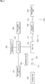
- FIG. 1 illustrates schematically a block diagram of a ballast water treatment operating apparatus according to one embodiment of the present invention.
- a ballast water treatment operating apparatus includes a pump 110 for intaking ballast water; a ballast water tank 135 for storing ballast water; and a first valve 121, a second valve 122, a third valve (ECU intake valve) 123, a fourth valve (ECU discharge valve), a fifth valve (bypass valve) 125, a sixth valve (tank discharge valve) 126, a seventh valve (tank intake valve) 127 and a eighth valve (deballast discharge valve) 128 for controlling the flow rate of ballast water.
- the ballast water treatment operating apparatus includes a plurality of units related with a ballast water treatment.
- the ballast water treatment operating apparatus includes an electrolysis unit (ECU) 146 for electrolyzing ballast water; a neutralization unit 142 for neutralizing TRO remaining in ballast water discharged during a deballast operation; a TRO sensor unit 148 for measuring TRO remaining in ballast water during a ballast or deballast operation; a flow rate detection unit 144 for detecting a flow during a ballast or deballast operation; and a power supply unit 160 for supplying a power to the above units.
- ECU electrolysis unit
- TRO used in this invention means the total residual oxidant existing in ballast water and is generally obtained by measuring a residual chlorine value of chlorine remained after chlorine generated via an electrolysis process oxidizes aquatic organisms within ballast water.
- seawater or salt water is electrolyzed or chlorine-sterilized, several kinds of oxidants coexist as a result of replacement of active chlorines by atoms such as bromine.
- the TRO indicates all active oxidants existing at this time.
- the ballast water treatment operating apparatus also includes a pump 110; a distribution board 150 for providing a state signal for each operation of a plurality of valves; a user inputting unit 170 operable to receive a user input; a positional information receiving unit 180 operable to communicate with a satellite; and a control unit 190 operable to communicate with and control the above units, wherein the control unit may comprise a personal computer and the like.
- the state signal of each valve means a state information detected according to operation of the pump 110 or each valve.
- a state signal of each valve may be a state-on signal when the valve is open.
- the positional information receiving unit 180 may include a GPS satellite communication module to receive positional information, and may also receive positional information directly from a user.
- the positional information receiving unit 180 may receive an operational condition updated through communication with an artificial satellite in case the positional information receiving unit 180 is provided with a satellite communication module.
- control unit 190 confirms a position as to a ship's latitude and longitude by using positional information received from the positional information receiving unit 180 when a ballast operation is to be performed.
- the control unit 190 performs a ballast operation without operating the electrolysis unit 146 if a ship's position is located in an area in which the electrolysis unit 146 does not need to be operated.
- control unit 190 operates the electrolysis unit 146 during a ballast operation if a ship's position is located in an area in which the electrolysis unit 146 has to be operated.
- control unit 190 confirms a position as to a ship's latitude and longitude by using positional information received from the positional information receiving unit 180 when a deballast operation is to be performed.
- the control unit 190 performs a deballast operation without operating the neutralization unit 142 if a ship's position is located in an area in which the neutralization unit 142 does not need to be operated.
- control unit 190 operates the neutralization unit 142 during a ballast operation if a ship's position is located in an area in which the neutralization unit 142 has to be operated.
- control unit 190 may further include a memory (not shown).
- a memory (not shown).
- the memory are stored an operational condition as to whether to operate the electrolysis unit 146 during a ballast operation and an operational condition as to whether to operate the neutralization unit 142 necessary during a deballast operation.
- control unit 190 determines whether to operate the electrolysis unit 146 according to the operational condition stored in the memory when a ballast operation is to be performed and determines whether to operate the neutralization unit 142 according to the operational condition stored in the memory when a deballast operation is to be performed.
- the condition by which the control unit 190 determines whether to perform an operation includes (1) whether the area where a ballast operation is performed is the same as that where a deballast operation is performed; (2) whether the area where a ballast or deballast operation is performed is under the Mutual Exemption Agreement and the like.
- the control unit 190 does not operate the electrolysis unit 146 if the area where a ballast operation is performed is the same as that where a deballast operation is performed or if the area where a ballast operation is performed is under the Mutual Exemption Agreement.
- control unit 190 may store in a memory an updated operational condition received at the positional information receiving unit 180.
- FIG. 2 illustrates schematically a block diagram of a ballast water treatment operating apparatus according to another embodiment of the present invention.
- a ballast water treatment operating apparatus includes a pump 210 for intaking ballast water; a ballast water tank 235 for storing ballast water; and a first valve 221, a second valve 222, a third valve 223, a fourth valve 224 and a fifth valve 225 for controlling the flow rate of ballast water.
- the ballast water treatment operating apparatus includes a plurality of units related with a ballast water treatment.
- the ballast water treatment operating apparatus includes a filter unit 240 for filtering detrimental substances, etc., of ballast water; an ultraviolet (UV) treatment unit 245 for performing UV treatment of ballast water; and a power supply unit 250 for supplying a power to the above units.
- a filter unit 240 for filtering detrimental substances, etc., of ballast water
- an ultraviolet (UV) treatment unit 245 for performing UV treatment of ballast water
- a power supply unit 250 for supplying a power to the above units.
- the ballast water treatment operating apparatus also includes a pump 210; a distribution board 260 for providing a state signal for each operation of a plurality of valves; a user inputting unit 270 operable to receive a user input; a positional information receiving unit 280 operable to communicate with a satellite; a control unit 290 operable to communicate with and control the above units, wherein the control unit may comprise a personal computer and the like.
- the state signal of each valve means a state information detected according to operation of the pump 210 or each valve.
- a state signal of each valve may be a state-on signal when the valve is open.
- the positional information receiving unit 280 may include a GPS satellite communication module to receive positional information, and may also receive positional information directly from a user.
- the positional information receiving unit 280 may receive an operational condition updated through communication with an artificial satellite in case the positional information receiving unit 180 is provided with a satellite communication module.
- the positional information receiving unit 280 includes GPS which receives positional information. In addition, the positional information receiving unit 280 may receive an operational condition updated through communication with an artificial satellite.
- control unit 290 confirms a position as to a ship's latitude and longitude by using positional information received from the positional information receiving unit 280 if a ballast operation is to be performed.
- the control unit 290 performs a ballast operation without operating an ultraviolet treatment unit 245 if a ship's position is located in an area in which the ultraviolet treatment unit 245 does not need to be operated.
- the control unit 290 operates the ultraviolet treatment unit 245 during a ballast operation if a ship's position is located in an area in which the ultraviolet treatment unit 245 has to be operated.
- control unit 290 confirms a position as to a ship's latitude and longitude by using positional information received from the positional information receiving unit 280 when a deballast operation is to be performed.
- the control unit 290 performs a deballast operation without operating the ultraviolet treatment unit 245 if a ship's position is located in an area in which the ultraviolet treatment unit 245 does not need to be operated.
- control unit 290 operates the ultraviolet treatment unit 245 during a ballast operation if a ship's position is located in an area in which the ultraviolet treatment unit 245 has to be operated.
- control unit 290 may further include a memory (not shown).
- a memory (not shown).
- the memory are stored an operational condition as to whether to operate the ultraviolet treatment unit 245 during a ballast operation and an operational condition as to whether to operate the ultraviolet treatment unit 245 necessary during a deballast operation.
- control unit 290 determines whether to operate the ultraviolet treatment unit 245 according to the operational condition stored in the memory when a ballast operation is to be performed and determines whether to operate the ultraviolet treatment unit 245 according to the operational condition stored in the memory when a deballast operation is to be performed.
- control unit 290 may store in a memory an updated operational condition received at the positional information receiving unit 280.
- the electrolysis unit, the neutralization unit or the ultraviolet treatment unit described in the above mentioned embodiments may be commonly called a ballast water treatment unit.
- FIG. 3 is a flow chart of a ballast operation according to one embodiment of the present invention.
- a crew may input a ballast operation instruction into a control unit 190 by pressing a ballast button (not shown) of a user inputting unit 170 when the crew is to proceed with a ballast operation (S302).
- first the control unit 190 controls a drive unit (not shown) such that a first valve 121, a second valve 122, a third valve 123, a fourth valve 124 and a seventh valve 127 are opened (S304).
- a first valve state-on signal, a second valve state-on signal, a third valve state-on signal, a fourth valve state-on signal and a seventh valve state-on signal may be provided to a distribution board 160.
- a fifth valve state-off signal, a sixth valve state-off signal and a eighth valve state-off signal may also be provided to the distribution board 160.
- control unit 190 may control the drive unit to operate a pump 110 (S306). According to an operation of the pump 110, a pump state-on signal may be provided to the distribution board 160.
- the control unit 190 may be configured to detect a flow rate of ballast water via a flow rate detection unit 144 if the pump 110 is operated (S308). The control unit 190 may determine that ballast water is flowing if a flow rate value obtained from the flow rate detection unit 144 is greater than or equal to a defined standard flow rate value, for example 500m 3 /h.
- the control unit 190 receives positional information from the positional information receiving unit 180 (S310).
- the control unit 190 store in a memory positional information of a ship which is to perform a ballast operation (S312).
- the control unit 190 checks whether a user selects a position to perform a deballast operation by manipulating a user inputting unit 170 (S314).
- the control unit 190 operates a ballast water treatment unit, that is the electrolysis unit 146 or the ultraviolet treatment unit 245 if a user does not select a position to perform a deballast operation (S320). Meanwhile, the control unit 190 may adjust a current supplied to the electrolysis unit 146 depending on a flow rate of ballast water detected by the flow rate detection unit 144.
- the control unit 190 may also measure a flow rate of ballast water by the flow rate detection unit 144 and control a current supplied to the electrolysis unit 146 such that a proper amount of TRO is generated by measuring TRO by the TRO sensor unit 148.
- the control unit 190 may control a flow rate of ballast water by controlling the pump 110 as necessary.
- the control unit 190 may be configured to store a deballast position if a position to perform a deballast operation is selected by a user (S316).
- the control unit 190 checks whether to be the unoperation condition of a ballast treatment (S318).
- the control unit 190 operates a ballast water treatment unit, that is to say the electrolysis unit 146 or the ultraviolet treatment unit 245 if not being an unoperation condition of a ballast treatment (S320).
- the control unit 190 also performs a ballast operation without operating a ballast water treatment unit, that is the electrolysis unit 146 or the ultraviolet treatment unit 245 if an unoperation condition of a ballast treatment is satisfied (S322).
- the control unit 190 may in particular stop operating the electrolysis unit 146 or the ultraviolet treatment unit 245 if a flow rate of ballast water is not detected at the flow rate detection unit 144 because the ballast water tank 135 is completely filled with ballast water.
- FIG. 4 is a flow chart of a deballast treatment operation according to another embodiment of the present invention.
- a crew may input a deballast operation instruction into a control unit 190 by pressing a deballast button (not shown) of a user inputting unit 170 when the crew is to proceed with a deballast operation (S402).
- the control unit 190 controls a drive unit (not shown) such that a second valve 122, a fifth valve 125, a sixth valve 126 and a eighth valve 128 are opened (S404).
- a second valve state-on signal, a fifth valve state-on signal, a sixth valve state-on signal and a eighth valve state-on signal may be provided for a distribution board 160.
- a first valve state-off signal, a third valve state-off signal, a fourth valve state-off signal and a seventh valve state-off signal may also be provided to the distribution board 160.
- control unit may control the drive unit to operate the pump 110 (S406).
- a pump state-on signal may be provided to the distribution board 160.
- the control unit 190 detects a flow rate of ballast water via a flow rate detection unit 144 if the pump 110 is operated (S408).
- the control unit 190 receives positional information from the positional information receiving unit 180 (S410).
- the control unit 190 store in a memory positional information of a ship which is to perform a deballast operation (S412).
- the control unit 190 checks whether to be an unoperation condition of a deballast treatment (S414).
- the control unit 190 operates a ballast water treatment unit, that is to say the neutralization unit 142 or the ultraviolet treatment unit 245 if not being an unoperation condition of a deballast treatment (S416), and performs a deballast operation without operating a ballast water treatment unit, that is to say the neutralization unit 142 or the ultraviolet treatment unit 245 if an unoperation condition of a deballast treatment is satisfied (S418).
- the control unit 190 may in particular stop operating the neutralization unit 142 or the ultraviolet treatment unit 245 if a flow rate of ballast water is not detected at the flow rate detection unit 144 because the ballast water tank 135 is completely empty of ballast water.
- the ballast water treatment operating apparatus may include a stride operation, a gravity ballast operation and a gravity deballast operation and the like, other than the above mentioned operation conditions and may also be provided with a selection switch manually operable by the manipulation of a crew.
- the ballast water treatment operating apparatus may store a log such as operation records, that is to say a flow rate and a treatment concentration.
Description
- The present invention relates to a ballast water treatment operating apparatus and method and particularly to a ballast water treatment operating apparatus and method for determining whether to operate a ballast water treatment by using positional information of a global positioning system (GPS).
- Ships carrying cargo at sea in most cases sail in the state of a full load of cargo thereof and then unload cargo, and come back again with empty load. In case ships return with empty load like this, they start sailing after filled with ballast water by introducing it into the inside of the ships for the ship's balance, stability, manoeuvrabiltiy improvement and the like.
- At this time, ballast water is filled in one port by means of the ballasting operation, then transferred to another port and discharged in the new port by means of the deballasting operation. Like this, as ballast water containing marine organisms and pathogens which is transferred from a long distance away is discharged, such a discharge may cause adverse effects disturbing the marine environment and ecosystem. Thus, the International Maritime Organism (IMO) has recently enacted the ballast water treatment regulation to prevent the disturbance of the environment and ecosystem.
- To remove danger caused by marine organisms and pathogens, ballast water treatment devices which electrolyze ballast water or sterilize it by injecting chemicals or by ultraviolet light, are generally used in ships. However, since ballast water entered into the ballast water tank or discharged from the ballast water tank is of a large capacity, the high power consumption is caused whenever such a treatment is done.
- Following documents are known in this technical field :
DE 10 2006 045 558 A1 ,EP 2 913 305 A1 ,KR 101 486 501 B1 US 2003/176971 A1 ,EP 2 977 355 A1 andKR 2015 0109 309 A - To solve the above mentioned problem, the present invention has an object to provide a ballast water treatment operating apparatus and method which determine whether to operate a ballast water treatment by using positional information of GPS.
- So as to obtain the object described above, a ballast water treatment operating apparatus according to one embodiment of the present invention may comprise: a ballast water treatment unit for performing a certain treatment of a ballast water flowing in from the outside for a ballast operation or performing a certain treatment of ballast water discharged into the outside for a de-ballast operation; a positional information receiving unit for receiving positional information; and a control unit for confirming a ship's position by using positional information received from the positional information receiving unit and then determining whether to operate the ballast water treatment unit during the ballast operation or during the de-ballast operation.
- In a further embodiment, the control unit may further comprise a memory for storing a position to perform the ballast operation, and the control unit may store in the memory the position to perform the ballast operation during the ballast operation and, in consideration of a ballast operation performing area stored in the memory at the time of the ballast operation, may determine whether to operate the ballast water treatment unit.
- In a further embodiment, an operational condition of the ballast water treatment unit required during the ballast operation or during the de-ballast operation may be stored in the memory, and the control unit may be configured to determine whether to operate the ballast water treatment unit according to the operational condition stored in the memory during the ballast operation or during the de-ballast operation.
- In a further embodiment, if an updated operational condition of the ballast water treatment unit is inputted via the positional information receiving unit, the control unit may be configured to store the updated operational condition of the ballast water treatment unit in the memory.
- In a further embodiment, the ballast water treatment unit may comprise an electrolysis unit for being capable of electrolyzing the ballast water flowing in from the outside during the ballast operation; and a neutralization unit for neutralizing residual oxidants remaining in ballast water discharged into the outside during the de-ballast operation, and the control unit may be configured to control the electrolysis unit by determining whether to operate the electrolysis unit during the ballast operation and may be also configured to control the neutralization unit by determining whether to operate the neutralization unit during the de-ballast operation.
- In a further embodiment, the ballast water treatment unit may comprise an ultraviolet treatment unit for performing an ultraviolet sterilization treatment of ballast water flowing in from the outside during the ballast operation or of ballast water discharged into the outside during the de-ballast operation, and the control unit may be configured to control the ultraviolet treatment unit by determining whether to operate the ultraviolet treatment unit during a ballast operation and during a de-ballast operation.
- So as to obtain the object described above, a ballast water treatment operating method according to another embodiment of the present invention may comprise the steps of: receiving a first positional information from a positional information receiving unit if a ballast operating button is inputted via a user inputting unit; storing in a memory the first positional information received from the positional information receiving unit at the step of receiving the first positional information; confirming whether positional information as to a position to perform a de-ballast operation via the user inputting unit is inputted; and performing a certain treatment of ballast water flowing in from the outside by operating a ballast water treatment unit if the positional information inputted at the confirmation step satisfies an operational condition of the ballast water treatment unit.
- In a further embodiment, the method may further comprise the steps of: receiving a second positional information from the positional information receiving unit if a de-ballast operating button is inputted via a user inputting unit; and performing a certain treatment of ballast water discharged into the outside by operating the ballast water treatment unit if an operational condition of the ballast water treatment unit is satisfied in consideration of the second positional information received from the positional information receiving unit at the second positional information receipt step and the first positional information stored in the memory.
- According to the above configuration, the present invention can prevent a needless energy consumption by determining whether to operate a ballast water treatment based on positional information.
- In addition, the present invention can determine whether to treat ballast water according to a deballasting operation performing area at the time of the deballasting operation.
- The above and other objects, features and advantages of the present invention will become more apparent to those of ordinary skill in the art by describing in detail exemplary embodiments thereof with reference to the accompanying drawings, in which:
-
FIG. 1 illustrates schematically a block diagram of a ballast water treatment operating apparatus according to one embodiment of the present invention; -
FIG. 2 illustrates schematically a block diagram of a ballast water treatment operating apparatus according to another embodiment of the present invention; -
FIG. 3 is a flow chart of a ballast operation according to one embodiment of the present invention; and -
FIG. 4 is a flow chart of a deballast treatment operation according to another embodiment of the present invention. - Exemplary embodiments of a ballast water treatment operating apparatus and method according to the present invention will be described in detail below with reference to the accompanying drawings. For reference, in relation with the description of the present invention, as the terms indicating constituent elements of the present invention are named in consideration of the function of the respective constituent elements, they will not be understood as the meaning of limitation of technical constituent elements of the present invention.
-
FIG. 1 illustrates schematically a block diagram of a ballast water treatment operating apparatus according to one embodiment of the present invention. - As illustrated in
FIG. 1 , a ballast water treatment operating apparatus includes apump 110 for intaking ballast water; aballast water tank 135 for storing ballast water; and afirst valve 121, asecond valve 122, a third valve (ECU intake valve) 123, a fourth valve (ECU discharge valve), a fifth valve (bypass valve) 125, a sixth valve (tank discharge valve) 126, a seventh valve (tank intake valve) 127 and a eighth valve (deballast discharge valve) 128 for controlling the flow rate of ballast water. - In addition, the ballast water treatment operating apparatus includes a plurality of units related with a ballast water treatment. To this end, the ballast water treatment operating apparatus includes an electrolysis unit (ECU) 146 for electrolyzing ballast water; a
neutralization unit 142 for neutralizing TRO remaining in ballast water discharged during a deballast operation; aTRO sensor unit 148 for measuring TRO remaining in ballast water during a ballast or deballast operation; a flowrate detection unit 144 for detecting a flow during a ballast or deballast operation; and apower supply unit 160 for supplying a power to the above units. - The term "TRO" used in this invention means the total residual oxidant existing in ballast water and is generally obtained by measuring a residual chlorine value of chlorine remained after chlorine generated via an electrolysis process oxidizes aquatic organisms within ballast water. In case seawater or salt water is electrolyzed or chlorine-sterilized, several kinds of oxidants coexist as a result of replacement of active chlorines by atoms such as bromine. The TRO indicates all active oxidants existing at this time.
- The ballast water treatment operating apparatus also includes a
pump 110; adistribution board 150 for providing a state signal for each operation of a plurality of valves; auser inputting unit 170 operable to receive a user input; a positionalinformation receiving unit 180 operable to communicate with a satellite; and acontrol unit 190 operable to communicate with and control the above units, wherein the control unit may comprise a personal computer and the like. Herein the state signal of each valve means a state information detected according to operation of thepump 110 or each valve. For example, in case a limit switch is provided at each valve, a state signal of each valve may be a state-on signal when the valve is open. - The positional
information receiving unit 180 may include a GPS satellite communication module to receive positional information, and may also receive positional information directly from a user. The positionalinformation receiving unit 180 may receive an operational condition updated through communication with an artificial satellite in case the positionalinformation receiving unit 180 is provided with a satellite communication module. - In the present invention the
control unit 190 confirms a position as to a ship's latitude and longitude by using positional information received from the positionalinformation receiving unit 180 when a ballast operation is to be performed. Thecontrol unit 190 performs a ballast operation without operating theelectrolysis unit 146 if a ship's position is located in an area in which theelectrolysis unit 146 does not need to be operated. However, thecontrol unit 190 operates theelectrolysis unit 146 during a ballast operation if a ship's position is located in an area in which theelectrolysis unit 146 has to be operated. - In addition, the
control unit 190 confirms a position as to a ship's latitude and longitude by using positional information received from the positionalinformation receiving unit 180 when a deballast operation is to be performed. Thecontrol unit 190 performs a deballast operation without operating theneutralization unit 142 if a ship's position is located in an area in which theneutralization unit 142 does not need to be operated. However, thecontrol unit 190 operates theneutralization unit 142 during a ballast operation if a ship's position is located in an area in which theneutralization unit 142 has to be operated. - To this end, the
control unit 190 may further include a memory (not shown). In the memory are stored an operational condition as to whether to operate theelectrolysis unit 146 during a ballast operation and an operational condition as to whether to operate theneutralization unit 142 necessary during a deballast operation. - Thus, the
control unit 190 determines whether to operate theelectrolysis unit 146 according to the operational condition stored in the memory when a ballast operation is to be performed and determines whether to operate theneutralization unit 142 according to the operational condition stored in the memory when a deballast operation is to be performed. - The condition by which the
control unit 190 determines whether to perform an operation includes (1) whether the area where a ballast operation is performed is the same as that where a deballast operation is performed; (2) whether the area where a ballast or deballast operation is performed is under the Mutual Exemption Agreement and the like. During a ballast operation, thecontrol unit 190 does not operate theelectrolysis unit 146 if the area where a ballast operation is performed is the same as that where a deballast operation is performed or if the area where a ballast operation is performed is under the Mutual Exemption Agreement. In case the area where a ballast operation is performed is the same as that where a deballast operation is performed, there is no need to operate deliberately theelectrolysis unit 146 during a ballast operation and also to operate deliberately theneutralization unit 142 during a deballast operation. - In addition, in case of agreeing that the application of 'the ballast water management convention' is exempted, like the areas under the Mutual Exemption Agreement, for example like Korea and Japan, there is also no need to operate deliberately the
electrolysis unit 146 during a ballast operation and also to operate deliberately theneutralization unit 142 during a deballast operation. - Also, the
control unit 190 may store in a memory an updated operational condition received at the positionalinformation receiving unit 180. -
FIG. 2 illustrates schematically a block diagram of a ballast water treatment operating apparatus according to another embodiment of the present invention. - As shown in
FIG. 2 , a ballast water treatment operating apparatus includes apump 210 for intaking ballast water; aballast water tank 235 for storing ballast water; and afirst valve 221, asecond valve 222, athird valve 223, a fourth valve 224 and afifth valve 225 for controlling the flow rate of ballast water. - In addition, the ballast water treatment operating apparatus includes a plurality of units related with a ballast water treatment. To this end, the ballast water treatment operating apparatus includes a
filter unit 240 for filtering detrimental substances, etc., of ballast water; an ultraviolet (UV)treatment unit 245 for performing UV treatment of ballast water; and apower supply unit 250 for supplying a power to the above units. - The ballast water treatment operating apparatus also includes a
pump 210; adistribution board 260 for providing a state signal for each operation of a plurality of valves; auser inputting unit 270 operable to receive a user input; a positionalinformation receiving unit 280 operable to communicate with a satellite; acontrol unit 290 operable to communicate with and control the above units, wherein the control unit may comprise a personal computer and the like. Herein the state signal of each valve means a state information detected according to operation of thepump 210 or each valve. For example, in case a limit switch is provided at each valve, a state signal of each valve may be a state-on signal when the valve is open. - The positional
information receiving unit 280 may include a GPS satellite communication module to receive positional information, and may also receive positional information directly from a user. The positionalinformation receiving unit 280 may receive an operational condition updated through communication with an artificial satellite in case the positionalinformation receiving unit 180 is provided with a satellite communication module. - The positional
information receiving unit 280 includes GPS which receives positional information. In addition, the positionalinformation receiving unit 280 may receive an operational condition updated through communication with an artificial satellite. - In the present invention the
control unit 290 confirms a position as to a ship's latitude and longitude by using positional information received from the positionalinformation receiving unit 280 if a ballast operation is to be performed. Thecontrol unit 290 performs a ballast operation without operating anultraviolet treatment unit 245 if a ship's position is located in an area in which theultraviolet treatment unit 245 does not need to be operated. However, thecontrol unit 290 operates theultraviolet treatment unit 245 during a ballast operation if a ship's position is located in an area in which theultraviolet treatment unit 245 has to be operated. - In addition, the
control unit 290 confirms a position as to a ship's latitude and longitude by using positional information received from the positionalinformation receiving unit 280 when a deballast operation is to be performed. Thecontrol unit 290 performs a deballast operation without operating theultraviolet treatment unit 245 if a ship's position is located in an area in which theultraviolet treatment unit 245 does not need to be operated. However, thecontrol unit 290 operates theultraviolet treatment unit 245 during a ballast operation if a ship's position is located in an area in which theultraviolet treatment unit 245 has to be operated. - To this end, the
control unit 290 may further include a memory (not shown). In the memory are stored an operational condition as to whether to operate theultraviolet treatment unit 245 during a ballast operation and an operational condition as to whether to operate theultraviolet treatment unit 245 necessary during a deballast operation. - Thus, the
control unit 290 determines whether to operate theultraviolet treatment unit 245 according to the operational condition stored in the memory when a ballast operation is to be performed and determines whether to operate theultraviolet treatment unit 245 according to the operational condition stored in the memory when a deballast operation is to be performed. - In addition, the
control unit 290 may store in a memory an updated operational condition received at the positionalinformation receiving unit 280. - Meanwhile, the electrolysis unit, the neutralization unit or the ultraviolet treatment unit described in the above mentioned embodiments may be commonly called a ballast water treatment unit.
-
FIG. 3 is a flow chart of a ballast operation according to one embodiment of the present invention. - A crew may input a ballast operation instruction into a
control unit 190 by pressing a ballast button (not shown) of auser inputting unit 170 when the crew is to proceed with a ballast operation (S302). - If the ballast operation instruction is inputted, in an embodiment of
FIG.1 , first thecontrol unit 190 controls a drive unit (not shown) such that afirst valve 121, asecond valve 122, athird valve 123, afourth valve 124 and aseventh valve 127 are opened (S304). Thus thefirst valve 121, thesecond valve 122, thethird valve 123, thefourth valve 124 and theseventh valve 127 may be operated to be opened, and a first valve state-on signal, a second valve state-on signal, a third valve state-on signal, a fourth valve state-on signal and a seventh valve state-on signal may be provided to adistribution board 160. In addition, a fifth valve state-off signal, a sixth valve state-off signal and a eighth valve state-off signal may also be provided to thedistribution board 160. - Next, the
control unit 190 may control the drive unit to operate a pump 110 (S306). According to an operation of thepump 110, a pump state-on signal may be provided to thedistribution board 160. - As described above, all signal from the
pump 110 or each valve have to be connected to thedistribution board 160 so as to provide thedistribution board 160 with a pump state signal and all valve state signals but this increases the cost. Therefore, it is preferable to provide the distribution board with some signals only necessary for a ballast operation and a deballast operation. - The
control unit 190 may be configured to detect a flow rate of ballast water via a flowrate detection unit 144 if thepump 110 is operated (S308). Thecontrol unit 190 may determine that ballast water is flowing if a flow rate value obtained from the flowrate detection unit 144 is greater than or equal to a defined standard flow rate value, for example 500m3/h. - The
control unit 190 receives positional information from the positional information receiving unit 180 (S310). Thecontrol unit 190 store in a memory positional information of a ship which is to perform a ballast operation (S312). - The
control unit 190 checks whether a user selects a position to perform a deballast operation by manipulating a user inputting unit 170 (S314). Thecontrol unit 190 operates a ballast water treatment unit, that is theelectrolysis unit 146 or theultraviolet treatment unit 245 if a user does not select a position to perform a deballast operation (S320). Meanwhile, thecontrol unit 190 may adjust a current supplied to theelectrolysis unit 146 depending on a flow rate of ballast water detected by the flowrate detection unit 144. Thecontrol unit 190 may also measure a flow rate of ballast water by the flowrate detection unit 144 and control a current supplied to theelectrolysis unit 146 such that a proper amount of TRO is generated by measuring TRO by theTRO sensor unit 148. Thecontrol unit 190 may control a flow rate of ballast water by controlling thepump 110 as necessary. - The
control unit 190 may be configured to store a deballast position if a position to perform a deballast operation is selected by a user (S316). Thecontrol unit 190 checks whether to be the unoperation condition of a ballast treatment (S318). Thecontrol unit 190 operates a ballast water treatment unit, that is to say theelectrolysis unit 146 or theultraviolet treatment unit 245 if not being an unoperation condition of a ballast treatment (S320). Thecontrol unit 190 also performs a ballast operation without operating a ballast water treatment unit, that is theelectrolysis unit 146 or theultraviolet treatment unit 245 if an unoperation condition of a ballast treatment is satisfied (S322). - The
control unit 190 may in particular stop operating theelectrolysis unit 146 or theultraviolet treatment unit 245 if a flow rate of ballast water is not detected at the flowrate detection unit 144 because theballast water tank 135 is completely filled with ballast water. -
FIG. 4 is a flow chart of a deballast treatment operation according to another embodiment of the present invention. - A crew may input a deballast operation instruction into a
control unit 190 by pressing a deballast button (not shown) of auser inputting unit 170 when the crew is to proceed with a deballast operation (S402). - If the ballast operation instruction is inputted, in an embodiment of
FIG.1 , first thecontrol unit 190 controls a drive unit (not shown) such that asecond valve 122, afifth valve 125, asixth valve 126 and aeighth valve 128 are opened (S404). Thus thesecond valve 122, thefifth valve 125, thesixth valve 126 and theeighth valve 128 may be operated to be opened, and a second valve state-on signal, a fifth valve state-on signal, a sixth valve state-on signal and a eighth valve state-on signal may be provided for adistribution board 160. In addition, a first valve state-off signal, a third valve state-off signal, a fourth valve state-off signal and a seventh valve state-off signal may also be provided to thedistribution board 160. - Next, the control unit may control the drive unit to operate the pump 110 (S406). According to an operation of the
pump 110, a pump state-on signal may be provided to thedistribution board 160. - The
control unit 190 detects a flow rate of ballast water via a flowrate detection unit 144 if thepump 110 is operated (S408). - The
control unit 190 receives positional information from the positional information receiving unit 180 (S410). Thecontrol unit 190 store in a memory positional information of a ship which is to perform a deballast operation (S412). - The
control unit 190 checks whether to be an unoperation condition of a deballast treatment (S414). Thecontrol unit 190 operates a ballast water treatment unit, that is to say theneutralization unit 142 or theultraviolet treatment unit 245 if not being an unoperation condition of a deballast treatment (S416), and performs a deballast operation without operating a ballast water treatment unit, that is to say theneutralization unit 142 or theultraviolet treatment unit 245 if an unoperation condition of a deballast treatment is satisfied (S418). - The
control unit 190 may in particular stop operating theneutralization unit 142 or theultraviolet treatment unit 245 if a flow rate of ballast water is not detected at the flowrate detection unit 144 because theballast water tank 135 is completely empty of ballast water. - The ballast water treatment operating apparatus may include a stride operation, a gravity ballast operation and a gravity deballast operation and the like, other than the above mentioned operation conditions and may also be provided with a selection switch manually operable by the manipulation of a crew. In addition, the ballast water treatment operating apparatus may store a log such as operation records, that is to say a flow rate and a treatment concentration.
- Embodiments of the present invention described above are simply illustrative of the technical concept of the present invention and the protective scope of the present invention should be interpreted by the appended claims. In addition, it will be apparent to those skilled in the art that various modifications and alterations can be made without departing from the essential features of the present invention. Thus, all technical concepts within the equivalent scope to the present invention should be interpreted to be included within the protective scope of the present invention.
Claims (8)
- A ballast water treatment operating apparatus comprising:a ballast water treatment unit for performing a certain treatment of a ballast water flowing in from the outside for a ballast operation or performing a certain treatment of ballast water discharged into the outside for a de-ballast operation;a positional information receiving unit (180, 280) for receiving a positional information; anda control unit (190, 290) for confirming a ship's position by using the positional information received from the positional information receiving unit (180, 280) and then determining whether to operate the ballast water treatment unit during the ballast operation or during the de-ballast operation;
wherein the control unit (190, 290) does not operate the ballast water treatment unit when the area where the ballast operation is performed is the same as the area where the de-ballast operation is performed or the area where the ballast operation or de-ballast operation is performed is under a Mutual Exemption Agreement stating that an application of a Ballast Water Management Convention is mutually exempted. - The ballast water operating apparatus of claim 1, wherein the control unit (190, 290) comprises a memory for storing a position to perform the ballast operation, and wherein the control unit (190, 290) stores in the memory the position to perform the ballast operation during the ballast operation and, in consideration of a ballast operation performing area stored in the memory at the time of the ballast operation, determines whether to operate the ballast water treatment unit.
- The ballast water operating apparatus of claim 2, wherein an operational condition of the ballast water treatment unit required during the ballast operation or during the de-ballast operation is stored in the memory, and wherein the control unit (190, 290) is configured to determine whether to operate the ballast water treatment unit according to the operational condition stored in the memory during the ballast operation or during the de-ballast operation.
- The ballast water treatment operating apparatus of claim 3, wherein if an updated operational condition of the ballast water treatment unit is inputted via the positional information receiving unit (180, 280), the control unit (190, 290) is configured to store the updated operational condition of the ballast water treatment unit in the memory.
- The ballast water treatment operating apparatus of any one of claims 1 to 4, wherein the ballast water treatment unit comprises an electrolysis unit (146) for being capable of electrolyzing the ballast water flowing in from the outside during the ballast operation; and a neutralization unit (142) for neutralizing residual oxidants remaining in ballast water discharged into the outside during the de-ballast operation, and
wherein the control unit (190, 290) is configured to control the electrolysis unit (146) by determining whether to operate the electrolysis unit (146) during the ballast operation and is also configured to control the neutralization unit (142) by determining whether to operate the neutralization unit (142) during the de-ballast operation. - The ballast water treatment operating apparatus of any one of claims 1 to 4, wherein the ballast water treatment unit comprises an ultraviolet treatment unit (245) for performing an ultraviolet sterilization treatment of ballast water flowing in from the outside during the ballast operation or of ballast water discharged into the outside during the de-ballast operation, and
wherein the control unit (190, 290) is configured to control the ultraviolet treatment unit (245) by determining whether to operate the ultraviolet treatment unit (245) during a ballast operation and during a de-ballast operation. - A ballast water treatment operating method for the ballast water treatment operating apparatus of claim 1, the method comprising the steps of:receiving a first positional information from a positional information receiving unit (180, 280) if a ballast operating button is inputted via a user inputting unit;confirming whether a second positional information as to a position to perform a de-ballast operation via the user inputting unit is inputted;determining whether the area where the ballast operation is performed is the same as the area where the de-ballast operation is performed or the area where the ballast operation and de-ballast operation are performed is under a Mutual Exemption Agreement stating that an application of a Ballast Water Management Convention is mutually exempted by using the first position information received in the receiving step and the second position information confirmed in the confirming step; andnot operating a ballast water treatment unit so as not to perform a predetermined process on the ballast water flowing from in the outside when the area where the ballast operation is performed is the same as the area where the de-ballast operation is performed and the area where the ballast operation or de-ballast operation is performed is under the Mutual Exemption Agreement.
- The method of claim 7, further comprising the steps of:receiving a second positional information from the positional information receiving unit (180, 280) if a de-ballast operating button is inputted via a user inputting unit; andperforming a certain treatment of ballast water discharged into the outside by operating the ballast water treatment unit if an operational condition of the ballast water treatment unit is satisfied in consideration of the second positional information received from the positional information receiving unit (180, 280) at the second positional information receipt step and the first positional information stored in the memory.
Priority Applications (1)
| Application Number | Priority Date | Filing Date | Title |
|---|---|---|---|
| EP16163894.5A EP3228532B1 (en) | 2016-04-05 | 2016-04-05 | Ballast water treatment operating apparatus and method |
Applications Claiming Priority (1)
| Application Number | Priority Date | Filing Date | Title |
|---|---|---|---|
| EP16163894.5A EP3228532B1 (en) | 2016-04-05 | 2016-04-05 | Ballast water treatment operating apparatus and method |
Publications (2)
| Publication Number | Publication Date |
|---|---|
| EP3228532A1 EP3228532A1 (en) | 2017-10-11 |
| EP3228532B1 true EP3228532B1 (en) | 2020-05-06 |
Family
ID=55697073
Family Applications (1)
| Application Number | Title | Priority Date | Filing Date |
|---|---|---|---|
| EP16163894.5A Active EP3228532B1 (en) | 2016-04-05 | 2016-04-05 | Ballast water treatment operating apparatus and method |
Country Status (1)
| Country | Link |
|---|---|
| EP (1) | EP3228532B1 (en) |
Family Cites Families (6)
| Publication number | Priority date | Publication date | Assignee | Title |
|---|---|---|---|---|
| US20030176971A1 (en) * | 2002-03-13 | 2003-09-18 | Daniels John James | Method and system for tracking the exchange of ballast water |
| DE102006045558A1 (en) * | 2006-09-25 | 2008-04-03 | Rwo Gmbh | Water treatment plant |
| KR101743849B1 (en) * | 2012-10-25 | 2017-06-05 | 파나소닉 아이피 매니지먼트 가부시키가이샤 | Method for treating ballast water and device for treating ballast water used therefor |
| EP2977355A4 (en) * | 2013-03-22 | 2016-03-16 | Tech Cross Co Ltd | Ballast water treatment system |
| KR101486501B1 (en) * | 2013-03-22 | 2015-01-26 | (주) 테크로스 | Ballast water treatment system |
| KR20150109309A (en) * | 2015-09-08 | 2015-10-01 | 김혁 | Sea water electrolysis device |
-
2016
- 2016-04-05 EP EP16163894.5A patent/EP3228532B1/en active Active
Non-Patent Citations (1)
| Title |
|---|
| None * |
Also Published As
| Publication number | Publication date |
|---|---|
| EP3228532A1 (en) | 2017-10-11 |
Similar Documents
| Publication | Publication Date | Title |
|---|---|---|
| KR101758830B1 (en) | Apparatus and method for treating ballast water by using electrolysis | |
| KR101331688B1 (en) | Salt water supplying apparatus for electrolysis unit of ballast water treating apparatus | |
| KR101669099B1 (en) | Operation apparatus and operation method for treatmenting ballast water | |
| EP3228532B1 (en) | Ballast water treatment operating apparatus and method | |
| KR102370466B1 (en) | Automatic operation method of seawater desalination device for seawater desalination vessel | |
| US10214274B2 (en) | Ballast water treatment operating apparatus and method | |
| JP2017185884A (en) | Ballast water treatment operation device and method | |
| US20170057833A1 (en) | Recirculating type active substance treatment system | |
| KR101205960B1 (en) | Ship having ballast tank using freshwater and sea water | |
| KR20190068348A (en) | Fresh water generating apparatus for ship and method thereof | |
| KR101472527B1 (en) | Treatment System and Treatment Method for Ballast Water | |
| KR101614585B1 (en) | Sea Water Supply System for Electrolysis Unit of Ballast Water Treatment System | |
| KR101715425B1 (en) | Supervisory system and method detecting low salinity region for ballast water management system | |
| KR20110010322A (en) | Conrol system and method therof for trfatment of ballast water | |
| KR102260200B1 (en) | Ballast Water Filter Bypass Control Methods for Ships | |
| CN107265712A (en) | Ballast water treatment operation device and method | |
| KR20220017820A (en) | Ballast water treatment apparatus | |
| KR20160026195A (en) | System for neutralizing ballast water | |
| JP5596454B2 (en) | Ship with ballast tank system | |
| KR101918570B1 (en) | TRO Sensing Equipment for Ballast water | |
| JP2022067405A (en) | Ballast water treatment device | |
| Fearnley | Lessons Learned in Ballast Water Treatment Equipment Retrofit and Commissioning | |
| KR20190091386A (en) | Ballast water treatment device and ballast water treatment method | |
| KR101554956B1 (en) | Ballast water treatment system capable of exactly measuring concentration of oxidizing agent | |
| WO2020217372A1 (en) | Ballast water treatment system and ship comprising same |
Legal Events
| Date | Code | Title | Description |
|---|---|---|---|
| PUAI | Public reference made under article 153(3) epc to a published international application that has entered the european phase |
Free format text: ORIGINAL CODE: 0009012 |
|
| STAA | Information on the status of an ep patent application or granted ep patent |
Free format text: STATUS: THE APPLICATION HAS BEEN PUBLISHED |
|
| AK | Designated contracting states |
Kind code of ref document: A1 Designated state(s): AL AT BE BG CH CY CZ DE DK EE ES FI FR GB GR HR HU IE IS IT LI LT LU LV MC MK MT NL NO PL PT RO RS SE SI SK SM TR |
|
| AX | Request for extension of the european patent |
Extension state: BA ME |
|
| STAA | Information on the status of an ep patent application or granted ep patent |
Free format text: STATUS: REQUEST FOR EXAMINATION WAS MADE |
|
| 17P | Request for examination filed |
Effective date: 20171121 |
|
| RBV | Designated contracting states (corrected) |
Designated state(s): AL AT BE BG CH CY CZ DE DK EE ES FI FR GB GR HR HU IE IS IT LI LT LU LV MC MK MT NL NO PL PT RO RS SE SI SK SM TR |
|
| RIC1 | Information provided on ipc code assigned before grant |
Ipc: B63J 4/00 20060101AFI20181128BHEP |
|
| STAA | Information on the status of an ep patent application or granted ep patent |
Free format text: STATUS: EXAMINATION IS IN PROGRESS |
|
| 17Q | First examination report despatched |
Effective date: 20190327 |
|
| GRAP | Despatch of communication of intention to grant a patent |
Free format text: ORIGINAL CODE: EPIDOSNIGR1 |
|
| STAA | Information on the status of an ep patent application or granted ep patent |
Free format text: STATUS: GRANT OF PATENT IS INTENDED |
|
| INTG | Intention to grant announced |
Effective date: 20191128 |
|
| GRAS | Grant fee paid |
Free format text: ORIGINAL CODE: EPIDOSNIGR3 |
|
| GRAA | (expected) grant |
Free format text: ORIGINAL CODE: 0009210 |
|
| STAA | Information on the status of an ep patent application or granted ep patent |
Free format text: STATUS: THE PATENT HAS BEEN GRANTED |
|
| AK | Designated contracting states |
Kind code of ref document: B1 Designated state(s): AL AT BE BG CH CY CZ DE DK EE ES FI FR GB GR HR HU IE IS IT LI LT LU LV MC MK MT NL NO PL PT RO RS SE SI SK SM TR |
|
| REG | Reference to a national code |
Ref country code: GB Ref legal event code: FG4D |
|
| REG | Reference to a national code |
Ref country code: CH Ref legal event code: EP Ref country code: AT Ref legal event code: REF Ref document number: 1266338 Country of ref document: AT Kind code of ref document: T Effective date: 20200515 |
|
| REG | Reference to a national code |
Ref country code: IE Ref legal event code: FG4D |
|
| REG | Reference to a national code |
Ref country code: DE Ref legal event code: R096 Ref document number: 602016035512 Country of ref document: DE |
|
| REG | Reference to a national code |
Ref country code: LT Ref legal event code: MG4D |
|
| REG | Reference to a national code |
Ref country code: NL Ref legal event code: MP Effective date: 20200506 |
|
| PG25 | Lapsed in a contracting state [announced via postgrant information from national office to epo] |
Ref country code: LT Free format text: LAPSE BECAUSE OF FAILURE TO SUBMIT A TRANSLATION OF THE DESCRIPTION OR TO PAY THE FEE WITHIN THE PRESCRIBED TIME-LIMIT Effective date: 20200506 Ref country code: SE Free format text: LAPSE BECAUSE OF FAILURE TO SUBMIT A TRANSLATION OF THE DESCRIPTION OR TO PAY THE FEE WITHIN THE PRESCRIBED TIME-LIMIT Effective date: 20200506 Ref country code: NO Free format text: LAPSE BECAUSE OF FAILURE TO SUBMIT A TRANSLATION OF THE DESCRIPTION OR TO PAY THE FEE WITHIN THE PRESCRIBED TIME-LIMIT Effective date: 20200806 Ref country code: GR Free format text: LAPSE BECAUSE OF FAILURE TO SUBMIT A TRANSLATION OF THE DESCRIPTION OR TO PAY THE FEE WITHIN THE PRESCRIBED TIME-LIMIT Effective date: 20200807 Ref country code: IS Free format text: LAPSE BECAUSE OF FAILURE TO SUBMIT A TRANSLATION OF THE DESCRIPTION OR TO PAY THE FEE WITHIN THE PRESCRIBED TIME-LIMIT Effective date: 20200906 Ref country code: FI Free format text: LAPSE BECAUSE OF FAILURE TO SUBMIT A TRANSLATION OF THE DESCRIPTION OR TO PAY THE FEE WITHIN THE PRESCRIBED TIME-LIMIT Effective date: 20200506 Ref country code: PT Free format text: LAPSE BECAUSE OF FAILURE TO SUBMIT A TRANSLATION OF THE DESCRIPTION OR TO PAY THE FEE WITHIN THE PRESCRIBED TIME-LIMIT Effective date: 20200907 |
|
| PG25 | Lapsed in a contracting state [announced via postgrant information from national office to epo] |
Ref country code: LV Free format text: LAPSE BECAUSE OF FAILURE TO SUBMIT A TRANSLATION OF THE DESCRIPTION OR TO PAY THE FEE WITHIN THE PRESCRIBED TIME-LIMIT Effective date: 20200506 Ref country code: HR Free format text: LAPSE BECAUSE OF FAILURE TO SUBMIT A TRANSLATION OF THE DESCRIPTION OR TO PAY THE FEE WITHIN THE PRESCRIBED TIME-LIMIT Effective date: 20200506 Ref country code: RS Free format text: LAPSE BECAUSE OF FAILURE TO SUBMIT A TRANSLATION OF THE DESCRIPTION OR TO PAY THE FEE WITHIN THE PRESCRIBED TIME-LIMIT Effective date: 20200506 Ref country code: BG Free format text: LAPSE BECAUSE OF FAILURE TO SUBMIT A TRANSLATION OF THE DESCRIPTION OR TO PAY THE FEE WITHIN THE PRESCRIBED TIME-LIMIT Effective date: 20200806 |
|
| REG | Reference to a national code |
Ref country code: AT Ref legal event code: MK05 Ref document number: 1266338 Country of ref document: AT Kind code of ref document: T Effective date: 20200506 |
|
| PG25 | Lapsed in a contracting state [announced via postgrant information from national office to epo] |
Ref country code: AL Free format text: LAPSE BECAUSE OF FAILURE TO SUBMIT A TRANSLATION OF THE DESCRIPTION OR TO PAY THE FEE WITHIN THE PRESCRIBED TIME-LIMIT Effective date: 20200506 Ref country code: NL Free format text: LAPSE BECAUSE OF FAILURE TO SUBMIT A TRANSLATION OF THE DESCRIPTION OR TO PAY THE FEE WITHIN THE PRESCRIBED TIME-LIMIT Effective date: 20200506 |
|
| PG25 | Lapsed in a contracting state [announced via postgrant information from national office to epo] |
Ref country code: CZ Free format text: LAPSE BECAUSE OF FAILURE TO SUBMIT A TRANSLATION OF THE DESCRIPTION OR TO PAY THE FEE WITHIN THE PRESCRIBED TIME-LIMIT Effective date: 20200506 Ref country code: RO Free format text: LAPSE BECAUSE OF FAILURE TO SUBMIT A TRANSLATION OF THE DESCRIPTION OR TO PAY THE FEE WITHIN THE PRESCRIBED TIME-LIMIT Effective date: 20200506 Ref country code: ES Free format text: LAPSE BECAUSE OF FAILURE TO SUBMIT A TRANSLATION OF THE DESCRIPTION OR TO PAY THE FEE WITHIN THE PRESCRIBED TIME-LIMIT Effective date: 20200506 Ref country code: DK Free format text: LAPSE BECAUSE OF FAILURE TO SUBMIT A TRANSLATION OF THE DESCRIPTION OR TO PAY THE FEE WITHIN THE PRESCRIBED TIME-LIMIT Effective date: 20200506 Ref country code: SM Free format text: LAPSE BECAUSE OF FAILURE TO SUBMIT A TRANSLATION OF THE DESCRIPTION OR TO PAY THE FEE WITHIN THE PRESCRIBED TIME-LIMIT Effective date: 20200506 Ref country code: EE Free format text: LAPSE BECAUSE OF FAILURE TO SUBMIT A TRANSLATION OF THE DESCRIPTION OR TO PAY THE FEE WITHIN THE PRESCRIBED TIME-LIMIT Effective date: 20200506 Ref country code: AT Free format text: LAPSE BECAUSE OF FAILURE TO SUBMIT A TRANSLATION OF THE DESCRIPTION OR TO PAY THE FEE WITHIN THE PRESCRIBED TIME-LIMIT Effective date: 20200506 Ref country code: IT Free format text: LAPSE BECAUSE OF FAILURE TO SUBMIT A TRANSLATION OF THE DESCRIPTION OR TO PAY THE FEE WITHIN THE PRESCRIBED TIME-LIMIT Effective date: 20200506 |
|
| REG | Reference to a national code |
Ref country code: DE Ref legal event code: R097 Ref document number: 602016035512 Country of ref document: DE |
|
| PG25 | Lapsed in a contracting state [announced via postgrant information from national office to epo] |
Ref country code: SK Free format text: LAPSE BECAUSE OF FAILURE TO SUBMIT A TRANSLATION OF THE DESCRIPTION OR TO PAY THE FEE WITHIN THE PRESCRIBED TIME-LIMIT Effective date: 20200506 Ref country code: PL Free format text: LAPSE BECAUSE OF FAILURE TO SUBMIT A TRANSLATION OF THE DESCRIPTION OR TO PAY THE FEE WITHIN THE PRESCRIBED TIME-LIMIT Effective date: 20200506 |
|
| PLBE | No opposition filed within time limit |
Free format text: ORIGINAL CODE: 0009261 |
|
| STAA | Information on the status of an ep patent application or granted ep patent |
Free format text: STATUS: NO OPPOSITION FILED WITHIN TIME LIMIT |
|
| 26N | No opposition filed |
Effective date: 20210209 |
|
| PG25 | Lapsed in a contracting state [announced via postgrant information from national office to epo] |
Ref country code: SI Free format text: LAPSE BECAUSE OF FAILURE TO SUBMIT A TRANSLATION OF THE DESCRIPTION OR TO PAY THE FEE WITHIN THE PRESCRIBED TIME-LIMIT Effective date: 20200506 |
|
| REG | Reference to a national code |
Ref country code: DE Ref legal event code: R119 Ref document number: 602016035512 Country of ref document: DE |
|
| PG25 | Lapsed in a contracting state [announced via postgrant information from national office to epo] |
Ref country code: MC Free format text: LAPSE BECAUSE OF FAILURE TO SUBMIT A TRANSLATION OF THE DESCRIPTION OR TO PAY THE FEE WITHIN THE PRESCRIBED TIME-LIMIT Effective date: 20200506 |
|
| GBPC | Gb: european patent ceased through non-payment of renewal fee |
Effective date: 20210405 |
|
| PG25 | Lapsed in a contracting state [announced via postgrant information from national office to epo] |
Ref country code: LU Free format text: LAPSE BECAUSE OF NON-PAYMENT OF DUE FEES Effective date: 20210405 |
|
| REG | Reference to a national code |
Ref country code: BE Ref legal event code: MM Effective date: 20210430 |
|
| PG25 | Lapsed in a contracting state [announced via postgrant information from national office to epo] |
Ref country code: FR Free format text: LAPSE BECAUSE OF NON-PAYMENT OF DUE FEES Effective date: 20210430 Ref country code: GB Free format text: LAPSE BECAUSE OF NON-PAYMENT OF DUE FEES Effective date: 20210405 Ref country code: DE Free format text: LAPSE BECAUSE OF NON-PAYMENT OF DUE FEES Effective date: 20211103 Ref country code: LI Free format text: LAPSE BECAUSE OF NON-PAYMENT OF DUE FEES Effective date: 20210430 Ref country code: CH Free format text: LAPSE BECAUSE OF NON-PAYMENT OF DUE FEES Effective date: 20210430 |
|
| PG25 | Lapsed in a contracting state [announced via postgrant information from national office to epo] |
Ref country code: IE Free format text: LAPSE BECAUSE OF NON-PAYMENT OF DUE FEES Effective date: 20210405 |
|
| PG25 | Lapsed in a contracting state [announced via postgrant information from national office to epo] |
Ref country code: BE Free format text: LAPSE BECAUSE OF NON-PAYMENT OF DUE FEES Effective date: 20210430 |
|
| PG25 | Lapsed in a contracting state [announced via postgrant information from national office to epo] |
Ref country code: HU Free format text: LAPSE BECAUSE OF FAILURE TO SUBMIT A TRANSLATION OF THE DESCRIPTION OR TO PAY THE FEE WITHIN THE PRESCRIBED TIME-LIMIT; INVALID AB INITIO Effective date: 20160405 |
|
| PG25 | Lapsed in a contracting state [announced via postgrant information from national office to epo] |
Ref country code: CY Free format text: LAPSE BECAUSE OF FAILURE TO SUBMIT A TRANSLATION OF THE DESCRIPTION OR TO PAY THE FEE WITHIN THE PRESCRIBED TIME-LIMIT Effective date: 20200506 |