EP3227828B1 - System and method for alternatively interacting with elevators - Google Patents
System and method for alternatively interacting with elevators Download PDFInfo
- Publication number
- EP3227828B1 EP3227828B1 EP15804476.8A EP15804476A EP3227828B1 EP 3227828 B1 EP3227828 B1 EP 3227828B1 EP 15804476 A EP15804476 A EP 15804476A EP 3227828 B1 EP3227828 B1 EP 3227828B1
- Authority
- EP
- European Patent Office
- Prior art keywords
- elevator
- operational
- person
- installation
- operational mode
- Prior art date
- Legal status (The legal status is an assumption and is not a legal conclusion. Google has not performed a legal analysis and makes no representation as to the accuracy of the status listed.)
- Active
Links
- 238000000034 method Methods 0.000 title claims description 30
- 230000008451 emotion Effects 0.000 claims description 66
- 238000009434 installation Methods 0.000 claims description 65
- 230000001815 facial effect Effects 0.000 claims description 25
- 230000007613 environmental effect Effects 0.000 claims description 10
- 238000005286 illumination Methods 0.000 claims description 4
- 230000006870 function Effects 0.000 claims description 3
- 230000007935 neutral effect Effects 0.000 claims description 3
- 238000005516 engineering process Methods 0.000 description 16
- 230000003993 interaction Effects 0.000 description 14
- 230000008921 facial expression Effects 0.000 description 10
- 238000012544 monitoring process Methods 0.000 description 9
- 230000006854 communication Effects 0.000 description 6
- 238000004891 communication Methods 0.000 description 6
- 238000010616 electrical installation Methods 0.000 description 6
- 230000008878 coupling Effects 0.000 description 5
- 238000010168 coupling process Methods 0.000 description 5
- 238000005859 coupling reaction Methods 0.000 description 5
- 230000009471 action Effects 0.000 description 4
- 230000002996 emotional effect Effects 0.000 description 3
- 239000011521 glass Substances 0.000 description 3
- 230000003287 optical effect Effects 0.000 description 3
- 206010001488 Aggression Diseases 0.000 description 2
- 229910000831 Steel Inorganic materials 0.000 description 2
- 208000003443 Unconsciousness Diseases 0.000 description 2
- 230000016571 aggressive behavior Effects 0.000 description 2
- 208000012761 aggressive behavior Diseases 0.000 description 2
- 238000005094 computer simulation Methods 0.000 description 2
- 238000001514 detection method Methods 0.000 description 2
- 238000009429 electrical wiring Methods 0.000 description 2
- 239000010959 steel Substances 0.000 description 2
- 206010003805 Autism Diseases 0.000 description 1
- 208000020706 Autistic disease Diseases 0.000 description 1
- 208000028698 Cognitive impairment Diseases 0.000 description 1
- 238000013459 approach Methods 0.000 description 1
- 238000013475 authorization Methods 0.000 description 1
- 230000006399 behavior Effects 0.000 description 1
- 230000007175 bidirectional communication Effects 0.000 description 1
- 230000008859 change Effects 0.000 description 1
- 208000010877 cognitive disease Diseases 0.000 description 1
- 150000001875 compounds Chemical class 0.000 description 1
- 238000013461 design Methods 0.000 description 1
- 238000003745 diagnosis Methods 0.000 description 1
- 238000010586 diagram Methods 0.000 description 1
- 230000007246 mechanism Effects 0.000 description 1
- 230000036651 mood Effects 0.000 description 1
- 210000003205 muscle Anatomy 0.000 description 1
- 230000008569 process Effects 0.000 description 1
- 238000012545 processing Methods 0.000 description 1
- 208000020016 psychiatric disease Diseases 0.000 description 1
- 201000000980 schizophrenia Diseases 0.000 description 1
- 230000005236 sound signal Effects 0.000 description 1
- 229920002994 synthetic fiber Polymers 0.000 description 1
- 230000001960 triggered effect Effects 0.000 description 1
- 230000001755 vocal effect Effects 0.000 description 1
Images

Classifications
-
- B—PERFORMING OPERATIONS; TRANSPORTING
- B66—HOISTING; LIFTING; HAULING
- B66B—ELEVATORS; ESCALATORS OR MOVING WALKWAYS
- B66B5/00—Applications of checking, fault-correcting, or safety devices in elevators
- B66B5/0006—Monitoring devices or performance analysers
- B66B5/0012—Devices monitoring the users of the elevator system
-
- G—PHYSICS
- G06—COMPUTING; CALCULATING OR COUNTING
- G06V—IMAGE OR VIDEO RECOGNITION OR UNDERSTANDING
- G06V40/00—Recognition of biometric, human-related or animal-related patterns in image or video data
- G06V40/10—Human or animal bodies, e.g. vehicle occupants or pedestrians; Body parts, e.g. hands
- G06V40/16—Human faces, e.g. facial parts, sketches or expressions
- G06V40/174—Facial expression recognition
-
- B—PERFORMING OPERATIONS; TRANSPORTING
- B66—HOISTING; LIFTING; HAULING
- B66B—ELEVATORS; ESCALATORS OR MOVING WALKWAYS
- B66B1/00—Control systems of elevators in general
- B66B1/24—Control systems with regulation, i.e. with retroactive action, for influencing travelling speed, acceleration, or deceleration
- B66B1/2408—Control systems with regulation, i.e. with retroactive action, for influencing travelling speed, acceleration, or deceleration where the allocation of a call to an elevator car is of importance, i.e. by means of a supervisory or group controller
-
- B—PERFORMING OPERATIONS; TRANSPORTING
- B66—HOISTING; LIFTING; HAULING
- B66B—ELEVATORS; ESCALATORS OR MOVING WALKWAYS
- B66B1/00—Control systems of elevators in general
- B66B1/34—Details, e.g. call counting devices, data transmission from car to control system, devices giving information to the control system
- B66B1/46—Adaptations of switches or switchgear
- B66B1/468—Call registering systems
-
- B—PERFORMING OPERATIONS; TRANSPORTING
- B66—HOISTING; LIFTING; HAULING
- B66B—ELEVATORS; ESCALATORS OR MOVING WALKWAYS
- B66B5/00—Applications of checking, fault-correcting, or safety devices in elevators
- B66B5/02—Applications of checking, fault-correcting, or safety devices in elevators responsive to abnormal operating conditions
- B66B5/021—Applications of checking, fault-correcting, or safety devices in elevators responsive to abnormal operating conditions the abnormal operating conditions being independent of the system
- B66B5/025—Applications of checking, fault-correcting, or safety devices in elevators responsive to abnormal operating conditions the abnormal operating conditions being independent of the system where the abnormal operating condition is caused by human behaviour or misbehaviour, e.g. forcing the doors
-
- B—PERFORMING OPERATIONS; TRANSPORTING
- B66—HOISTING; LIFTING; HAULING
- B66B—ELEVATORS; ESCALATORS OR MOVING WALKWAYS
- B66B2201/00—Aspects of control systems of elevators
- B66B2201/40—Details of the change of control mode
- B66B2201/405—Details of the change of control mode by input of special passenger or passenger group
-
- B—PERFORMING OPERATIONS; TRANSPORTING
- B66—HOISTING; LIFTING; HAULING
- B66B—ELEVATORS; ESCALATORS OR MOVING WALKWAYS
- B66B2201/00—Aspects of control systems of elevators
- B66B2201/40—Details of the change of control mode
- B66B2201/46—Switches or switchgear
- B66B2201/4607—Call registering systems
- B66B2201/4676—Call registering systems for checking authorization of the passengers
Definitions
- the various embodiments described herein generally relate to electromechanical or electrical installations, such as elevator installations, that require interactions with humans. More particularly, the various embodiments described herein relate to electromechanical or electrical installations and a method for operating electromechanical or electrical installations with improved man-machine interaction.
- a user typically interacts with the installation via a man-machine interface (for example, an operating panel with keys or buttons, or a touchscreen).
- a man-machine interface for example, an operating panel with keys or buttons, or a touchscreen.
- an elevator user interacts with the elevator via an operating terminal, also referred to as a fixture.
- An operating terminal may be located inside an elevator car to place a car call (i.e., to enter a destination floor), another operating terminal is then located on each floor to enter a hall call (i.e., to call a car to a floor by pressing an "up" or "down” button).
- the destination floor is already entered at a floor terminal before entering an elevator car.
- the interaction between the elevator user and the elevator occurs typically via fixtures/operating panels, even when, e.g., an RFID card is used to call an elevator.
- US 7,298,256 describes a crisis monitoring system that detects a crisis by identifying a person's emotion from an utterance of the person.
- a recording unit records emotion attribute information, which includes a feature of a specific emotion in an audio signal (i.e., in the person's voice), and a control unit determines a person's emotion by analyzing the emotion attribute information.
- an emergency routine is executed which includes alerting a control center or a security company.
- An analysis of a vocal input to determine a person's state of mind or mood is also disclosed in WO 2009/116030 in the context of an access control system.
- the system inquires a person at a checkpoint to determine the person's identity and to decide whether or not access is to be granted to a person present at the checkpoint.
- US 2012/120219 A1 discloses an electronic device that may be a computer, a notebook computer, a computer server, a communication device (e.g., a mobile phone), a personal digital assistant, or any other computing device to calm or ease the emotions of workers.
- the electronic device includes an emotion management system, a processor, a storage device, a display, a speaker, and at least one camera module.
- the electronic device provides a relaxation method to counteract human emotion and to calm or settle a person.
- US 2005/264425 A1 discloses a crisis monitoring system in which a user who desires crisis monitoring carries a crisis monitoring terminal around.
- a crisis monitoring equipment may be installed in an elevator, and watches for a crisis upon receiving a monitoring signal from the user's crisis monitoring terminal.
- the crisis monitoring system analyzes voice information to determine if a user is in trouble. If this is the case, the control unit may control automatic running of the elevator.
- Other information than a person's voice may be monitored as long as it shows what situation a user is in, and that a camera may be used to observe a user's behavior and to determine that the user is feeling a specific emotion when a specific motion or a specific facial expression is detected.
- Another aspect involves an elevator installation according to independent claim 9.
- the technology described herein provides for an alternative way of interacting with persons. That interaction may occur without a person actively participating in the interaction.
- the person's facial expression may therefore be genuine and reflect the person's actual emotional state. Determining the emotional state allows adapting the installation's operational modes to certain situations.
- the person is a passenger in an elevator car of an elevator installation. From a psychological perspective, using elevators is for some passengers challenging because of the confined space of a car and the closeness to other passengers. If those passengers and their emotional states are recognized, it is possible to adjust the operational mode to make using an elevator more pleasant. Further, potential risks due to, for example, angry passengers with an aggressive behavior can be identified and addressed as early as possible. For example, such a passenger may receive special treatment, e.g., faster service without stops, or may be prohibited from using the elevator when found to be a security risk.
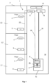
- Fig. 1 illustrates one embodiment of an elevator installation 1 as one example of an electrical or electromechanical installation.
- the various embodiments of the improved technology are described herein with reference to that elevator installation 1 that allows user interaction to provide for transportation between floors L1, L2, L3 of a building 2. It is, however, contemplated that the technology may be applied to other electrical or electromechanical installations that usually require user interaction, such as building access systems, public transportation systems or security/surveillance monitoring systems.
- user interaction means any interaction between a user and an electrical or electromechanical installation, whether intentional or unintentional, conscious or unconscious.
- An example of an intentional interaction is entering a command at a man- machine interface, e.g., by pressing a button, touching a sensor, presenting an information carrier (such as a badge with a bar code or an RFID transponder) or uttering a command.
- an information carrier such as a badge with a bar code or an RFID transponder
- being observed by a video camera in a public place, including an elevator lobby may be unintentional, conscious or unconscious.
- Such interaction may result in an action (e.g., alarm, change of operation) performed by the electrical or electromechanical installation.
- the elevator system 1 includes an elevator car 10 and a central controller 12 (also referred to as elevator controller 12 (EC)) that acts on a drive 14 to move the elevator car 10, for example suspended by one or more tension members 16, in an elevator shaft 18, from one of the floors L1, L2, L3 to another.
- a tension member 16 may by a steel rope having a round cross-section, or a group of (steel or non-metallic) cords embedded in synthetic material having a non-round cross-section, e.g., a rectangular cross-section.
- the general physical structure of the elevator installation 1 corresponds to the physical structure of a conventional elevator installation.
- the physical structure includes in addition to the mentioned elements (central controller 12, drive 14 and tension member 16) a counterweight, guide rails for the elevator car 10 and the counterweight, safety equipment such as brakes and safety circuits for door mechanisms, etc.
- these elements are not shown.
- the configuration and disposition of these elements in a shaft 18 may vary.
- the drive 14 may be arranged in a separate machine room or directly in the shaft 18 ("machine room less elevator") at the top, as shown, or at the bottom of the shaft 18. The operation of such an elevator installation 1 is known to the skilled person and, therefore, not described here.
- the elevator installation 1 of Fig. 1 includes a system for capturing at least one parameter of a user.
- a user parameter capturing system is based upon digital video technology to generate an image signal corresponding to an individual image or a sequence of images (frames), i.e., a video sequence.
- a video camera 4 may be used, which can be operated to generate individual pictures or a video sequence.
- the image signal may be processed in real time.
- the pictures or video sequence may be stored on an internal storage medium of the video camera 4 or transmitted to an external storage medium.
- a video camera 4 may be installed on each floor L1, L2, L3, as shown in Fig. 1 . In another embodiment, however, some of the floors L1, L2, L3 may not be equipped with a video camera 4. In certain buildings 2 it may suffice to have a video camera 4 only in the lobby, e.g., on floor L1.
- An additional video camera 6 may be positioned within the elevator car 10, as shown in Fig. 1 . In such an embodiment, an indicator 6b may be positioned inside the elevator car 10 to inform passengers when the video camera 6 is recording.
- the video cameras 4, 6 are communicatively coupled to a computer 8, which controls the operation of the video cameras 4, 6 and receives transmitted video information (i.e., image signals) from them. As described below in more detail, the computer 8 processes that video information and generates in certain situations a control signal for the elevator controller 12. For that purpose, the computer 8 is communicatively coupled to the elevator controller 12.
- a communicative connection or coupling as used herein is a direct or indirect connection, which enables the unidirectional or bidirectional communication between two entities. Via such a connection or coupling, data signals and/or control signals are transmitted in a manner known to the skilled person.
- the connection or coupling may be achieved by an electrical wiring system (either as a system of point-to-point connections or as an electrical bus system, where entities connected to the bus system can be addressed), a radio system or a combination of a radio system and an electrical wiring system.
- Fig. 1 shows the communicative coupling exemplary through lines 20, 22, wherein the line 20 extends between the computer 8 and the elevator car 10, and the line 22 extends between the computer 8 and the video camera 4.
- the line 22 is a bus system to which the video cameras 4 are connected.
- the computer 8 or its functionality of controlling the video cameras 4, 6 and executing a dedicated software program may be implemented, for example, in the elevator controller 12 or in another electrical component of the building 2, e.g., in an access control system that controls access to the building 2, floors L1, L2, L2 and/or rooms of the building 2.
- the separately shown computer 8 might be omitted from Fig. 1 .
- the implementation of the communicative connection or coupling changes accordingly.
- Fig. 1 therefore, is to be viewed as an exemplary embodiment.
- a video monitor may be present within the building 2 or at a remote site that displays all or only selected video recordings (e. g., from the building 2 to allow security personnel to monitor the building 2.
- Fig. 1 further shows input devices 5, 7 that are communicatively coupled to the elevator controller 12 and the computer 8.
- an input device 5 is located to allow a person to interact with the elevator installation 1, e. g., to call an elevator.
- the input device 7 is located inside the elevator car 10 and may be implemented as part of an operating panel that houses the video camera 6, the indicator 6b, and the input device 7.
- the video camera 6 may be positioned at the upper end of the operating panel so that the video camera 6 has an optimized view over the interior of the elevator car 10. In that case, the video camera 6 is located close to the ceiling to provide for video recordings from an elevated position. In that case, the camera's field of view is least obstructed by passengers inside the elevator car 10. Close to the ceiling, the video camera 6 may be out of reach so that the risk of vandalism is reduced. Covering the video camera 6 or placing it behind the glass front further reduces the risk of damage. It is contemplated that the same considerations regarding location and protection apply to the video cameras 4 installed at the floors L1, L2, L3.
- the input device 7 may in one embodiment include a keyboard to allow a passenger to enter a car call, i.e., after entering into the elevator car 10 the passenger can enter a destination floor via the keyboard.
- the input device 5 on the floor L1, L2, L3 may have Up/Down buttons to allow a waiting passenger to call an elevator.
- the elevator installation may be equipped with a destination call control system. Such a system allows a person to enter a destination floor via the input device 5 already on the floor L1, L2, L3 before boarding the elevator car 10.
- the input device 5 or at the input device 7, or both may be configured to read information from an information carrier carried by a person/passenger.
- the respective input device 5, 7 is equipped with a reader to read data from that information carrier when it is presented to the reader.
- the read data may represent an authorization to operate the input device 5, 7 or a destination call, or both.
- the information carrier has a form factor that corresponds to a credit card or an employee badge.
- the information carrier includes an embedded memory chip having leads to the surface of the information carrier, an embedded RFID transponder in connection with a memory chip, an optical code on the surface (e.g., a barcode or QR code), or a combination of these technologies.
- the functionality of the information carrier may be implemented in a portable electronic device (e.g., mobile phone, smart phone or tablet PC). These devices may display optical codes, and may also allow radio communication with other electronic devices using known technologies such as Bluetooth or NFC (near field communication). It is contemplated that the reader is compatible with the technology, or the several technologies, used by the information carrier
- FIG. 2 shows a block diagram of an exemplary embodiment of a computer 8 (e.g., part of an access control system control unit, part of the elevator controller 12, part of a reader, part of a database) that can be used with one or more technologies disclosed herein.
- the computer 8 comprises one or more processors 24.
- the processor 24 is coupled to a memory 26, which comprises one or more computer-readable storage media storing software instructions 28 and a database.
- the computer-readable storage media can comprise, for example, one or more of optical disks, volatile memory components (such as DRAM or SRAM), or nonvolatile memory components (such as hard drives, Flash RAM or ROM).
- the software instructions 28 When executed by the processor 24, the software instructions 28 cause the processor 24 to perform one or more of the method steps disclosed herein.
- Further embodiments of the computer 8 can comprise one or more additional components.
- the computer 8 can be connected to one or more other computers or electronic devices through an input/output component (interface) 30.
- the computer 8 can connect to other computers or electronic devices through a network.
- the computer 8 works with one or more other computers, which may be located locally, remotely, or both. One or more of the disclosed methods can thus be performed using a distributed computing system.
- FIG. 3 This figure describes an exemplary flowchart of a method of operating the elevator installation 1.
- the method starts at a step S1 and ends at a step S7.
- an image signal is received.
- the computer 8 receives an image signal from one of the video cameras 4 on one of the floors L1, L2, L3.
- the image signal represents an image or a sequence of video images (e.g., a sequence of video frames).
- the video cameras 4, 6 may be in constant operation regardless of the actual operational status of the elevator installation 1.
- a video camera 4, 6 may be activated when triggered by a specific event.
- the video cameras 4, 6 may be activated when movement is detected on a floor L1, L2, L3, or in the elevator car 10, or upon demand (e.g., by security personnel).
- facial characteristics are determined from a person's face data comprised in the image signal.
- the facial characteristics are derived from a person's facial expression using the computer instructions 28 and the database stored in the memory 28 of the computer 8.
- Computer-assisted analysis of facial expressions is described, for example, in Shichuan Du, et al., "Compound Facial Expressions of Emotion", published online March 31, 2014 at www.pnas.org/cgi/doi/10.1073/pnas.1322355111, pages E1454-E1462 .
- That publication describes a computer model that allows recognition of 21 different facial expressions of emotion, including happy, suddenly surprised, suddenly disgusted, surprised, sad, fearful, arguably fearful, fearful angry, fearful surprised, angry, remarkably angry, disappointment, disgusted, appalled, and awed.
- the publication uses a facial action coding system given by a set of action units. Each action unit codes the fundamental actions of individual or groups of muscles typically seen while producing facial expressions of emotion.
- psychiatric disorders e.g., schizophrenia
- cognitive impairments e.g., autism
- the computer 8 performs an analysis of a person's facial expression on basis of that computer model.
- the computer instructions 28 and the database of the computer 8 may first perform an analysis of the received image signal to locate the person's face in an image.
- a computer to locate a face in a video image is described, for example, in US 8,494,231 B2 .
- US 8,494,231 describes running input on-demand video through a processing pipeline having integrated modules that perform face detection, face tracking, face grouping and face recognition to generate face galleries.
- an algorithm for detecting the location of a face in an image is described in J.
- the various facial expressions and associated emotions are categorized for the specific application in the elevator installation 1. This is based on the assumption that certain emotions may be more or less of a concern for that specific elevator application. For example, a happy person may not be of any concern, but an angry person may be a concern when having to travel with several passengers in an elevator car 10.
- the determined facial characteristics are evaluated to determine if they fit in one of defined categories of emotion. If the facial characteristics fit, the method proceeds along the YES branch to a step S5. In the step S5, the computer 8 generates a control signal that is associated with the category into which the facial characteristics fit.
- the determined facial characteristics may not fit in one of the defined categories. For example, this may happen if the image signal does not allow an unambiguous detection of a face because the person turned the face away from the video camera 4, 6 or because of poor illumination of the scene. To avoid the latter case, the area observed by a video camera 4, 6 is to be sufficiently illuminated. In such situations, the computer 8 is in one embodiment set to assign no facial characteristics to the person; this is viewed herein as a "no fit.” In that case, the method returns along the NO branch to the step S3.
- the elevator installation 1 may be operated according to one of several operational modes. Each operational mode is associated with a particular control signal.
- the control signal generated in the step S5 determines which operational mode is to be selected so that the operational mode is selected as a function of the control signal. Proceeding to a step S6, the central controller 12 operates the electrical or electromechanical installation 1 in accordance with the selected operational mode.
- the first category is defined as neutral and includes emotions like happy, suddenly surprised, suddenly disgusted and surprised.
- the first operational mode is selected when the facial characteristics fit in the first emotion category.
- the central controller 12 operates the electrical or electromechanical installation 1 according to predetermined first operational settings, wherein the first operational settings correspond to predefined normal operation settings.
- the emotions in the first category are viewed as not requiring particular settings or parameters so that the installation 1 is operated according to its normal settings.
- a passenger showing emotions of the first category can be assigned any available car 10 without considering settings or parameters that affect the performance (e.g., service time, occupancy) or environment (e.g., illumination/light, sound (music), audio/video (multimedia) or temperature within the elevator car 10).
- settings or parameters that affect the performance e.g., service time, occupancy
- environment e.g., illumination/light, sound (music), audio/video (multimedia) or temperature within the elevator car 10.
- the second category includes sad and fearful emotions including emotions like arguably fearful, fearful angry and fearful surprised.
- the second operational mode is selected when the facial characteristics fit in the second emotion category.
- the central controller 12 operates the electrical or electromechanical installation 1 according to predetermined second operational settings that modify environmental parameters of the electrical or electromechanical installation 1. For example, a passenger showing emotions of the second category may require more attention that one with emotions of the first category to make the elevator trip more pleasant and enjoyable.
- Environmental parameters that may affect the passenger's emotions include the light, sound (music), audio/video (multimedia) or temperature within the elevator car 10.
- the third category includes angry and ashamed emotions including emotions like surprisingly angry.
- the third operational mode is selected when the facial characteristics fit in the third emotion category.
- the central controller 12 operates the electrical or electromechanical installation 1 according to predetermined third operational settings that affect the performance of the electrical or electromechanical installation 1. For example, an angry or ashamed passenger may show aggressive behavior within a crowded elevator car 10 and affect other passengers. To avoid such a situation, that passenger may be better served by assigning an empty car 10 to the passenger. Alternatively, or in addition to the previous measure, the angry passenger's call may be handled first to reduce the passenger's waiting time. Also, a trip without intermediate stops may be provided. Considering the installation 1 as a whole, these measures affect its performance. In some cases the performance is reduced because other passengers have to wait longer due to a trip without intermediate stops.
- the fourth category includes disgusted and appalled emotions including emotions like awed.
- the fourth operational mode is selected when the facial characteristics fit in the fourth emotion category.
- the central controller 12 operates the electrical or electromechanical installation 1 according to predetermined fourth operational settings that modify environmental parameters of the electrical or electromechanical installation 1.
- the environmental parameters can be those described in connection with the second operational mode.
- the elevator installation 1 is equipped with a destination control system and has several elevator cars 10 available to handle the traffic.
- a person approaches an elevator landing on a floor L1, L2, L3 where a video camera 4 is installed.
- the user presents an electronic card (an RFID card) to a reader of the input device 5 that is positioned on that floor L1, L2, L3.
- the reader reads credential information from the card (in this case, an identification number associated with the person and a destination floor) and sends this information to the elevator controller 12.
- the elevator controller 12 uses this information to determine that the person is authorized to use the elevator, and to assign an elevator car 10 to service that person's call.
- the computer 8 While the person is at the landing, the computer 8 executes the computer instructions 28, determines the person's facial characteristics, assigns them to a category, and selects the most suitable operational mode for that category. For example, if the person is angry or seems ashamed (third category), which may cause stress, the computer 8 generates a control signal that sets the third operational mode. That mode is set to optimize the time of an elevator trip between placing a call and arriving at the destination floor. That time may be referred to as "service time" of the elevator trip. In one embodiment, that mode requires immediate service with no stops so that the (angry, stressed) person is transported to the destination floor as quickly as possible.
- the elevator car 10 may stop during a trip without the doors opening, e.g., between floors L1, L2, L3. In such a case, it usually takes some time until service personnel arrives on site to solve the problem. Although every person in the elevator car 10 knows that help is on its way, a person may not tolerate being stuck in such a confined space, either alone or with unknown persons. With the video camera 6 being active, the computer 8 could determine if a person is losing its temper, e.g., becomes angry (third category) or fearful (second category). If this is detected early, the computer 8 may generate a control signal that sets the most appropriate operational mode.
- the computer 8 may cause communications with the interior of the car 10, such as providing an announcement with instructions and/or information. For example, information may be provided about when the service technician will arrive, or, if a multimedia system is available inside the elevator car 10, the location of the service technician could be illustrated on a map. Having information like that may comfort and/or distract the passenger.
- method acts are performed in an order other than as disclosed herein, as long as that order is consistent with the order in independent claim 1.
- two or more method acts can be combined into one method act.
- one method act can be divided into two or more method acts.
Landscapes
- Engineering & Computer Science (AREA)
- General Physics & Mathematics (AREA)
- Oral & Maxillofacial Surgery (AREA)
- General Health & Medical Sciences (AREA)
- Human Computer Interaction (AREA)
- Physics & Mathematics (AREA)
- Health & Medical Sciences (AREA)
- Multimedia (AREA)
- Theoretical Computer Science (AREA)
- Automation & Control Theory (AREA)
- Computer Networks & Wireless Communication (AREA)
- Indicating And Signalling Devices For Elevators (AREA)
- Elevator Control (AREA)
Applications Claiming Priority (2)
| Application Number | Priority Date | Filing Date | Title |
|---|---|---|---|
| EP14196092 | 2014-12-03 | ||
| PCT/EP2015/078441 WO2016087557A1 (en) | 2014-12-03 | 2015-12-03 | System and method for alternatively interacting with elevators |
Publications (2)
| Publication Number | Publication Date |
|---|---|
| EP3227828A1 EP3227828A1 (en) | 2017-10-11 |
| EP3227828B1 true EP3227828B1 (en) | 2023-10-04 |
Family
ID=52011042
Family Applications (1)
| Application Number | Title | Priority Date | Filing Date |
|---|---|---|---|
| EP15804476.8A Active EP3227828B1 (en) | 2014-12-03 | 2015-12-03 | System and method for alternatively interacting with elevators |
Country Status (6)
| Country | Link |
|---|---|
| US (1) | US10457521B2 (zh) |
| EP (1) | EP3227828B1 (zh) |
| CN (1) | CN107000982B (zh) |
| AU (3) | AU2015357147A1 (zh) |
| CA (1) | CA2967723C (zh) |
| WO (1) | WO2016087557A1 (zh) |
Families Citing this family (19)
| Publication number | Priority date | Publication date | Assignee | Title |
|---|---|---|---|---|
| SG11201608516XA (en) * | 2014-05-23 | 2016-12-29 | Inventio Ag | Configuring terminal devices |
| CN107000982B (zh) * | 2014-12-03 | 2020-06-09 | 因温特奥股份公司 | 与电梯交替交互的系统和方法 |
| EP3299326A1 (en) | 2016-08-24 | 2018-03-28 | Otis Elevator Company | Communication with a trapped passenger in a transportation system |
| WO2018075463A1 (en) * | 2016-10-17 | 2018-04-26 | Otis Elevator Company | Elevator systems and methods of controlling elevators responsive to detected passenger states |
| US10544007B2 (en) | 2017-03-23 | 2020-01-28 | International Business Machines Corporation | Risk-aware management of elevator operations |
| WO2018188956A1 (de) * | 2017-04-10 | 2018-10-18 | Inventio Ag | Zugangskontrollsystem mit funk- und gesichtserkennung |
| CN111212802B (zh) * | 2017-10-30 | 2021-06-29 | 株式会社日立制作所 | 电梯使用日志输出系统以及电梯使用日志输出方法 |
| US10961082B2 (en) * | 2018-01-02 | 2021-03-30 | Otis Elevator Company | Elevator inspection using automated sequencing of camera presets |
| US11040851B2 (en) * | 2018-04-26 | 2021-06-22 | Otis Elevator Company | Elevator system passenger frustration reduction |
| CN110526058B (zh) * | 2018-05-23 | 2022-06-03 | 奥的斯电梯公司 | 电梯门监控系统、电梯系统和电梯门监控方法 |
| CN109711299A (zh) * | 2018-12-17 | 2019-05-03 | 北京百度网讯科技有限公司 | 车辆客流统计方法、装置、设备及存储介质 |
| CN110738777A (zh) * | 2019-09-27 | 2020-01-31 | 恒大智慧科技有限公司 | 物业管理方法和系统、存储介质 |
| CN111232788B (zh) * | 2020-02-13 | 2021-07-20 | 江苏弘冉智能科技有限公司 | 一种电梯全要素健康及安全监控系统 |
| EP4143116A4 (en) * | 2020-04-29 | 2024-01-24 | Kone Corp | SOLUTION FOR GENERATING A CONTACTLESS ELEVATOR CALL |
| CN111960226B (zh) * | 2020-08-14 | 2021-11-16 | 安徽迅立达电梯有限公司 | 一种基于数据采集的电梯内部环境调节系统 |
| WO2022038303A1 (en) * | 2020-08-19 | 2022-02-24 | Kone Corporation | Controlling audio-visual stimuli inside an elevator car |
| CN114074864A (zh) * | 2020-08-20 | 2022-02-22 | 通力电梯有限公司 | 电梯控制方法、电梯控制系统和电梯系统 |
| CN112950413A (zh) * | 2021-03-18 | 2021-06-11 | 浙江三锁实业有限公司 | 一种楼宇智能管理方法、装置、智能终端及存储介质 |
| CN113968529B (zh) * | 2021-10-13 | 2023-04-14 | 上海梯之星信息科技有限公司 | 电梯安全提醒方法及装置 |
Family Cites Families (19)
| Publication number | Priority date | Publication date | Assignee | Title |
|---|---|---|---|---|
| US7079669B2 (en) * | 2000-12-27 | 2006-07-18 | Mitsubishi Denki Kabushiki Kaisha | Image processing device and elevator mounting it thereon |
| EP1526477B1 (en) * | 2002-07-26 | 2010-05-19 | Mitsubishi Denki Kabushiki Kaisha | Image processing apparatus |
| JP4627152B2 (ja) * | 2004-06-01 | 2011-02-09 | 三星電子株式会社 | 危機監視システム |
| JP5448817B2 (ja) | 2006-08-25 | 2014-03-19 | オーチス エレベータ カンパニー | 目的階登録配車運転においてセキュリティ保護の追跡を匿名で行う乗客指標付けシステム |
| JP4906490B2 (ja) * | 2006-12-13 | 2012-03-28 | 株式会社日立製作所 | エレベーター情報表示装置 |
| IL190232A (en) | 2008-03-17 | 2013-05-30 | Fst21 Ltd | Automatic / Semi-automatic incoming sorting system and method |
| CN101853623A (zh) | 2009-04-03 | 2010-10-06 | 鸿富锦精密工业(深圳)有限公司 | 影像监控系统及具有该系统的资讯显示系统 |
| CN101734527A (zh) * | 2009-12-31 | 2010-06-16 | 上海杰远环保科技有限公司 | 一种人脸识别电梯预定系统及其实现方法 |
| WO2011104807A1 (ja) | 2010-02-23 | 2011-09-01 | 三菱電機株式会社 | エレベーター装置 |
| TWI411978B (zh) * | 2010-04-14 | 2013-10-11 | Hon Hai Prec Ind Co Ltd | 電梯安全監控系統及方法 |
| CN102858670B (zh) | 2010-04-20 | 2014-08-13 | 三菱电机株式会社 | 电梯呼梯登记装置 |
| US8494231B2 (en) | 2010-11-01 | 2013-07-23 | Microsoft Corporation | Face recognition in video content |
| TW201220216A (en) * | 2010-11-15 | 2012-05-16 | Hon Hai Prec Ind Co Ltd | System and method for detecting human emotion and appeasing human emotion |
| JP5806916B2 (ja) | 2011-11-22 | 2015-11-10 | 株式会社日立製作所 | エレベーターのセキュリティシステム |
| WO2013121425A1 (en) | 2012-02-14 | 2013-08-22 | Fst21 Ltd. | System and method for entrance control to secured premises |
| JP5877135B2 (ja) | 2012-07-20 | 2016-03-02 | 株式会社日立製作所 | 画像認識装置及びエレベータ装置 |
| CN103896141A (zh) | 2012-12-30 | 2014-07-02 | 天津联一科技有限公司 | 基于图像处理技术的电梯门系统新型系统 |
| CN107000982B (zh) * | 2014-12-03 | 2020-06-09 | 因温特奥股份公司 | 与电梯交替交互的系统和方法 |
| US9610510B2 (en) | 2015-07-21 | 2017-04-04 | Disney Enterprises, Inc. | Sensing and managing vehicle behavior based on occupant awareness |
-
2015
- 2015-12-03 CN CN201580065098.1A patent/CN107000982B/zh active Active
- 2015-12-03 CA CA2967723A patent/CA2967723C/en active Active
- 2015-12-03 WO PCT/EP2015/078441 patent/WO2016087557A1/en active Application Filing
- 2015-12-03 AU AU2015357147A patent/AU2015357147A1/en not_active Abandoned
- 2015-12-03 EP EP15804476.8A patent/EP3227828B1/en active Active
- 2015-12-03 US US15/532,370 patent/US10457521B2/en active Active
-
2018
- 2018-12-18 AU AU2018282280A patent/AU2018282280A1/en not_active Abandoned
-
2021
- 2021-01-04 AU AU2021200009A patent/AU2021200009B2/en active Active
Also Published As
| Publication number | Publication date |
|---|---|
| CN107000982A (zh) | 2017-08-01 |
| CA2967723C (en) | 2023-05-23 |
| US20170362054A1 (en) | 2017-12-21 |
| EP3227828A1 (en) | 2017-10-11 |
| CA2967723A1 (en) | 2016-06-09 |
| AU2021200009B2 (en) | 2022-01-27 |
| AU2018282280A1 (en) | 2019-01-17 |
| CN107000982B (zh) | 2020-06-09 |
| AU2021200009A1 (en) | 2021-02-25 |
| WO2016087557A1 (en) | 2016-06-09 |
| AU2015357147A1 (en) | 2017-06-29 |
| US10457521B2 (en) | 2019-10-29 |
Similar Documents
| Publication | Publication Date | Title |
|---|---|---|
| EP3227828B1 (en) | System and method for alternatively interacting with elevators | |
| US9079749B2 (en) | Simple node transportation system and node controller and vehicle controller therein | |
| JP6529669B2 (ja) | エレベータ運行管理装置 | |
| EP3070039A1 (en) | System and method for allocating space inside elevator cars | |
| EP3560871B1 (en) | Elevator system passenger frustration reduction | |
| JP2005306584A (ja) | エレベータ自動運転システム及びプログラム | |
| CN113148788B (zh) | 基于乘客的定位在电梯轿厢中显示轿厢操作面板的系统和方法 | |
| US20210214185A1 (en) | Interface device, an elevator system, and a method for controlling of displaying of a plurality of destination calls | |
| US20210214186A1 (en) | Interface device, an elevator system, and a method for controlling displaying of a destination call | |
| JPWO2019087242A1 (ja) | エレベーター運行管理システム及び運行管理方法 | |
| US20230049228A1 (en) | Solution for generating a touchless elevator call | |
| JP2013234050A (ja) | エレベータ制御装置およびエレベータ制御方法 | |
| US20230002189A1 (en) | Access control system, an elevator system, and a method for controlling an access control system | |
| JP5208386B2 (ja) | エレベータ管理システム | |
| KR101257729B1 (ko) | 엘리베이터 사용자의 탑승 내역 추적 방법 및 이를 이용한 엘리베이터 | |
| WO2019060110A1 (en) | SYSTEM FOR MONITORING AND CONTROLLING ELEVATOR TRAFFIC | |
| JP2012006711A (ja) | エレベータの群管理システム | |
| JP6420210B2 (ja) | エレベータ装置及びエレベータ装置の制御方法 | |
| JP2019184969A (ja) | 案内ロボットシステム及び言語選択方法 | |
| WO2023281631A1 (ja) | エレベーター制御システムおよび制御方法 | |
| JP2006264819A (ja) | エレベータ防犯システム | |
| JP2023014522A (ja) | 情報表示システム及び情報表示方法 |
Legal Events
| Date | Code | Title | Description |
|---|---|---|---|
| STAA | Information on the status of an ep patent application or granted ep patent |
Free format text: STATUS: THE INTERNATIONAL PUBLICATION HAS BEEN MADE |
|
| PUAI | Public reference made under article 153(3) epc to a published international application that has entered the european phase |
Free format text: ORIGINAL CODE: 0009012 |
|
| STAA | Information on the status of an ep patent application or granted ep patent |
Free format text: STATUS: REQUEST FOR EXAMINATION WAS MADE |
|
| 17P | Request for examination filed |
Effective date: 20170523 |
|
| AK | Designated contracting states |
Kind code of ref document: A1 Designated state(s): AL AT BE BG CH CY CZ DE DK EE ES FI FR GB GR HR HU IE IS IT LI LT LU LV MC MK MT NL NO PL PT RO RS SE SI SK SM TR |
|
| AX | Request for extension of the european patent |
Extension state: BA ME |
|
| DAV | Request for validation of the european patent (deleted) | ||
| DAX | Request for extension of the european patent (deleted) | ||
| STAA | Information on the status of an ep patent application or granted ep patent |
Free format text: STATUS: EXAMINATION IS IN PROGRESS |
|
| 17Q | First examination report despatched |
Effective date: 20190423 |
|
| STAA | Information on the status of an ep patent application or granted ep patent |
Free format text: STATUS: EXAMINATION IS IN PROGRESS |
|
| STAA | Information on the status of an ep patent application or granted ep patent |
Free format text: STATUS: EXAMINATION IS IN PROGRESS |
|
| RAP3 | Party data changed (applicant data changed or rights of an application transferred) |
Owner name: INVENTIO AG |
|
| REG | Reference to a national code |
Ref country code: DE Ref legal event code: R079 Ref document number: 602015085968 Country of ref document: DE Free format text: PREVIOUS MAIN CLASS: G06K0009000000 Ipc: G06V0040160000 Ref country code: DE Ref legal event code: R079 Free format text: PREVIOUS MAIN CLASS: G06K0009000000 Ipc: G06V0040160000 |
|
| RIC1 | Information provided on ipc code assigned before grant |
Ipc: B66B 5/00 20060101ALI20230428BHEP Ipc: G06V 40/16 20220101AFI20230428BHEP |
|
| GRAP | Despatch of communication of intention to grant a patent |
Free format text: ORIGINAL CODE: EPIDOSNIGR1 |
|
| STAA | Information on the status of an ep patent application or granted ep patent |
Free format text: STATUS: GRANT OF PATENT IS INTENDED |
|
| INTG | Intention to grant announced |
Effective date: 20230620 |
|
| GRAS | Grant fee paid |
Free format text: ORIGINAL CODE: EPIDOSNIGR3 |
|
| GRAA | (expected) grant |
Free format text: ORIGINAL CODE: 0009210 |
|
| STAA | Information on the status of an ep patent application or granted ep patent |
Free format text: STATUS: THE PATENT HAS BEEN GRANTED |
|
| AK | Designated contracting states |
Kind code of ref document: B1 Designated state(s): AL AT BE BG CH CY CZ DE DK EE ES FI FR GB GR HR HU IE IS IT LI LT LU LV MC MK MT NL NO PL PT RO RS SE SI SK SM TR |
|
| REG | Reference to a national code |
Ref country code: GB Ref legal event code: FG4D |
|
| REG | Reference to a national code |
Ref country code: CH Ref legal event code: EP |
|
| REG | Reference to a national code |
Ref country code: IE Ref legal event code: FG4D |
|
| REG | Reference to a national code |
Ref country code: DE Ref legal event code: R096 Ref document number: 602015085968 Country of ref document: DE |
|
| PGFP | Annual fee paid to national office [announced via postgrant information from national office to epo] |
Ref country code: GB Payment date: 20231219 Year of fee payment: 9 |
|
| REG | Reference to a national code |
Ref country code: LT Ref legal event code: MG9D |
|
| PGFP | Annual fee paid to national office [announced via postgrant information from national office to epo] |
Ref country code: FR Payment date: 20231226 Year of fee payment: 9 |
|
| REG | Reference to a national code |
Ref country code: NL Ref legal event code: MP Effective date: 20231004 |
|
| REG | Reference to a national code |
Ref country code: AT Ref legal event code: MK05 Ref document number: 1618559 Country of ref document: AT Kind code of ref document: T Effective date: 20231004 |
|
| PG25 | Lapsed in a contracting state [announced via postgrant information from national office to epo] |
Ref country code: NL Free format text: LAPSE BECAUSE OF FAILURE TO SUBMIT A TRANSLATION OF THE DESCRIPTION OR TO PAY THE FEE WITHIN THE PRESCRIBED TIME-LIMIT Effective date: 20231004 |
|
| PG25 | Lapsed in a contracting state [announced via postgrant information from national office to epo] |
Ref country code: GR Free format text: LAPSE BECAUSE OF FAILURE TO SUBMIT A TRANSLATION OF THE DESCRIPTION OR TO PAY THE FEE WITHIN THE PRESCRIBED TIME-LIMIT Effective date: 20240105 |
|
| PG25 | Lapsed in a contracting state [announced via postgrant information from national office to epo] |
Ref country code: IS Free format text: LAPSE BECAUSE OF FAILURE TO SUBMIT A TRANSLATION OF THE DESCRIPTION OR TO PAY THE FEE WITHIN THE PRESCRIBED TIME-LIMIT Effective date: 20240204 |
|
| PG25 | Lapsed in a contracting state [announced via postgrant information from national office to epo] |
Ref country code: LT Free format text: LAPSE BECAUSE OF FAILURE TO SUBMIT A TRANSLATION OF THE DESCRIPTION OR TO PAY THE FEE WITHIN THE PRESCRIBED TIME-LIMIT Effective date: 20231004 |
|
| PG25 | Lapsed in a contracting state [announced via postgrant information from national office to epo] |
Ref country code: AT Free format text: LAPSE BECAUSE OF FAILURE TO SUBMIT A TRANSLATION OF THE DESCRIPTION OR TO PAY THE FEE WITHIN THE PRESCRIBED TIME-LIMIT Effective date: 20231004 |
|
| PG25 | Lapsed in a contracting state [announced via postgrant information from national office to epo] |
Ref country code: ES Free format text: LAPSE BECAUSE OF FAILURE TO SUBMIT A TRANSLATION OF THE DESCRIPTION OR TO PAY THE FEE WITHIN THE PRESCRIBED TIME-LIMIT Effective date: 20231004 |
|
| PG25 | Lapsed in a contracting state [announced via postgrant information from national office to epo] |
Ref country code: LT Free format text: LAPSE BECAUSE OF FAILURE TO SUBMIT A TRANSLATION OF THE DESCRIPTION OR TO PAY THE FEE WITHIN THE PRESCRIBED TIME-LIMIT Effective date: 20231004 Ref country code: IS Free format text: LAPSE BECAUSE OF FAILURE TO SUBMIT A TRANSLATION OF THE DESCRIPTION OR TO PAY THE FEE WITHIN THE PRESCRIBED TIME-LIMIT Effective date: 20240204 Ref country code: GR Free format text: LAPSE BECAUSE OF FAILURE TO SUBMIT A TRANSLATION OF THE DESCRIPTION OR TO PAY THE FEE WITHIN THE PRESCRIBED TIME-LIMIT Effective date: 20240105 Ref country code: ES Free format text: LAPSE BECAUSE OF FAILURE TO SUBMIT A TRANSLATION OF THE DESCRIPTION OR TO PAY THE FEE WITHIN THE PRESCRIBED TIME-LIMIT Effective date: 20231004 Ref country code: BG Free format text: LAPSE BECAUSE OF FAILURE TO SUBMIT A TRANSLATION OF THE DESCRIPTION OR TO PAY THE FEE WITHIN THE PRESCRIBED TIME-LIMIT Effective date: 20240104 Ref country code: AT Free format text: LAPSE BECAUSE OF FAILURE TO SUBMIT A TRANSLATION OF THE DESCRIPTION OR TO PAY THE FEE WITHIN THE PRESCRIBED TIME-LIMIT Effective date: 20231004 Ref country code: PT Free format text: LAPSE BECAUSE OF FAILURE TO SUBMIT A TRANSLATION OF THE DESCRIPTION OR TO PAY THE FEE WITHIN THE PRESCRIBED TIME-LIMIT Effective date: 20240205 |
|
| PGFP | Annual fee paid to national office [announced via postgrant information from national office to epo] |
Ref country code: DE Payment date: 20231227 Year of fee payment: 9 Ref country code: CH Payment date: 20240101 Year of fee payment: 9 |