EP3227158B1 - Vorrichtung zur absorption der energie von stössen von eisenbahnwagen - Google Patents
Vorrichtung zur absorption der energie von stössen von eisenbahnwagen Download PDFInfo
- Publication number
- EP3227158B1 EP3227158B1 EP15821166.4A EP15821166A EP3227158B1 EP 3227158 B1 EP3227158 B1 EP 3227158B1 EP 15821166 A EP15821166 A EP 15821166A EP 3227158 B1 EP3227158 B1 EP 3227158B1
- Authority
- EP
- European Patent Office
- Prior art keywords
- rod
- guiding part
- angular
- cutting tools
- angular guiding
- Prior art date
- Legal status (The legal status is an assumption and is not a legal conclusion. Google has not performed a legal analysis and makes no representation as to the accuracy of the status listed.)
- Active
Links
Images


Classifications
-
- B—PERFORMING OPERATIONS; TRANSPORTING
- B61—RAILWAYS
- B61G—COUPLINGS; DRAUGHT AND BUFFING APPLIANCES
- B61G11/00—Buffers
- B61G11/16—Buffers absorbing shocks by permanent deformation of buffer element
-
- B—PERFORMING OPERATIONS; TRANSPORTING
- B61—RAILWAYS
- B61G—COUPLINGS; DRAUGHT AND BUFFING APPLIANCES
- B61G11/00—Buffers
- B61G11/18—Details
-
- B—PERFORMING OPERATIONS; TRANSPORTING
- B61—RAILWAYS
- B61G—COUPLINGS; DRAUGHT AND BUFFING APPLIANCES
- B61G9/00—Draw-gear
- B61G9/20—Details; Accessories
-
- F—MECHANICAL ENGINEERING; LIGHTING; HEATING; WEAPONS; BLASTING
- F16—ENGINEERING ELEMENTS AND UNITS; GENERAL MEASURES FOR PRODUCING AND MAINTAINING EFFECTIVE FUNCTIONING OF MACHINES OR INSTALLATIONS; THERMAL INSULATION IN GENERAL
- F16F—SPRINGS; SHOCK-ABSORBERS; MEANS FOR DAMPING VIBRATION
- F16F7/00—Vibration-dampers; Shock-absorbers
- F16F7/12—Vibration-dampers; Shock-absorbers using plastic deformation of members
- F16F7/127—Vibration-dampers; Shock-absorbers using plastic deformation of members by a blade element cutting or tearing into a quantity of material; Pultrusion of a filling material
Definitions
- the present invention relates to a device absorbing the energy of impacts of railway cars, applicable particularly in railway central couplers.
- An impact energy absorption device comprising a rod suitable for being cut by the surrounding cutting tools arranged uniformly in the body sleeve is known from patent description PL202114 .
- the blades of these tools are placed in guides formed on the outer surface of the rod.
- an impact energy absorption device comprising a rod, with a smoothly varying diameter, suitable for being cut by means of cutting tools.
- the rod takes the form of a conic, pyramid or other curvilinear form to provide increased energy absorption capacity in the event of collisions of high kinetic energy.
- the invention US 4,346,795 describes a device absorbing energy of impact of railway cars, comprising a rod, a part of which is suitable for being cut by means of surrounding cutting tools mounted in a body sleeve and oriented to the inside thereof.
- the aim of the invention is to provide an impact energy absorbing device with increased resistance to lateral forces which, with its simple construction, would be able to absorb high energy in an emergency such as collision of railway cars and to protect these cars from damage, in particular, with increased angular deviations occurring between the cars hitting each other.
- the device of the invention comprises a rod with a part suitable for being cut by surrounding cutting tools mounted in a body sleeve and oriented to the inside of the sleeve.
- the invention is characterized in that the rod has an angular guiding part with a surface inclined relative to an axis of the rod, wherein the angular guiding part of the rod is connected with a lug pivotally attached to a support, and the body sleeve with the attached cutting tools is connected to the support by means of breakable elements.
- the lug is embedded in the holes of the support by an axle perpendicular to the axis of the rod.
- breakable elements are screws with a determined strength.
- the surface of the angular guiding part is inclined at an angle within the range from 7° to 30° relative to the axis of the rod, more preferably between 11° to 23°, and even more preferably between 12° to 18°.
- the angular guiding part is conical in shape.
- the rod has an increasing wall thickness in the angular guiding part.
- the lug embedded in the holes of the support has a cylindrical part intended to be embedded in the slot formed in the angular guiding part of the rod.
- a hardness of the surface layer of the initial region of the angular guiding part surface is greater than the limit of machinability, wherein the closer to the part of the rod suitable for being cut, the hardness of the surface layer of the angular guiding part decreases below the limit of machinability.
- the pivoted fixing of the rod in the support and the use of breakable elements connecting the body sleeve with the support allow for easier alignment of the rod with the contact of its angular guiding part with the cutting tools mounted in the body sleeve.
- screws with determined strength as the breakable elements simplifies the construction since the screws are used in the device according to the invention at the same time as fasteners and safety components, determining the limit of the exerted by the cars on each other pressure force at which the energy absorption by machining is triggered.
- Inclination of the surface of the guiding part at the angle within the range from 7° to 30° relative to the axis of the rod allows efficient alignment of the rod with respect to the body sleeve with cutting tools.
- Increasing the inclination above the limit of 30° could cause the driving of the cutting tools into the initial area of the angular guiding part and its deformation, and thereby prevent the displacement of the body sleeve with the cutting tools into the area of the rod intended for being cut.
- Increasing the thickness of the walls of the angular guiding part is intended to increase the modulus of rigidity and prevent deformation in this area.
- a cylindrical part of the lug allows its exact axial seating relative to the rod axis.
- Hardening of the outer layer of the initial area of the angular guiding part is intended to produce the sliding contact of the cutting tools in this initial area, thereby providing better guidance of the further part of the rod, suitable for being cut, relative to the body sleeve with the cutting tools, and thus, more effective alignment of the rod with respect to said body sleeve.
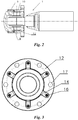
- FIG. 1 shows the device according to the invention absorbing the energy of impacts of railway cars at rest, before impact, in a top view with a partial axial section
- Fig. 2 the energy absorbing device at rest, in a side view with a partial axial section
- Fig. 3 the energy absorbing device in a front view
- Fig. 4 the energy absorbing device in a perspective view
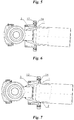
- Fig. 5 the device according to the invention in a top view, such as in Fig. 1 , at the first step of guidance
- Fig. 6 the device according to the invention at the final step of guidance
- Fig. 7 the device according to the invention at the step of operation.
- the rod 1 is in the form of the sleeve with a substantially constant thickness in the part 2 suitable for being cut, and in the frustoconical form in the guiding part 3.
- the end region of the guiding part 3 has also a function of the area intended both for guiding and for initial cutting.
- the guiding part 3 has a formed cylindrical axial slot 4, in which a cylindrical part 5 of a lug 6 is mounted.
- the said cylindrical part 5 is also welded to the face of the angular guiding part 3.
- the execution of the angular guiding part 3 in the form of a truncated cone with the cylindrical slot 4 enables obtaining the increasing thickness of that part as it approaches the part 2 suitable for being cut.
- a hole 7 of the lug 6 and holes 8 of the support 9 house an axle 10, perpendicular to axis 11 of the rod 1, allowing for the pivoted attachment of the lug 6, and thereby the pivoted attachment of the whole rod 1.
- the support 9 is fixed to a body sleeve 12 with breakable elements 13 in the form of screws with a determined tensile strength. Proper selection of the quantity, diameter and material strength of the screws allows to determine the limit at which the detachment of the body sleeve 12 from the support 9 occurs and, therefore, allows to determine the limit of the energy existing between the railway cars striking each other, at which the step of kinetic energy absorption by cutting is triggered.
- the body sleeve 12 is provided with cutting tools 14 distributed circumferentially and fixed on its front part. The cutting tools 14 are oriented into the interior of the body sleeve 12, and tips 15 of the blades of these cutting tools 14 are arranged on a smaller diameter than the diameter of the cylindrical part 2 of the rod 1.
- the rod 1 has an initial part of the angular surface of the guiding part 3 hardened to a value within the range of 45-55 HRC with the hardness of the cutting tools within the range of 58-63 HRC.
- the initial area of the angular surface of the guiding part 3 was adopted the lateral surface of a truncated cone starting with its smallest diameter and extending to half its height.
- the remainder of the angular guiding part 3 has the hardness decreasing as approaching the largest diameter, wherein from the diameter of the cone corresponding to the diameter of the distribution of the tips 15 of the blades of the cutting tools 14, the angular surface hardness is the smallest and has a value within the range of 27-30 HRC.
- the whole sleeve part 2 suitable for cutting has also the same hardness.
- the hardness of the sleeve part 2 suitable for cutting increases in the direction of the travel of cutting tools from the hardness within the range of 27-30 HRC to the limit of machinability i.e. 38-43 HRC, with the hardness of the cutting tool blades within the range of 58-63 HRC.
- the difference in the hardness of the blade of the cutting tool and the hardness of the cut part equal 20 HRC was adopted as the limit of machinability, therefore, with a blade hardness of 58 HRC, the limit value of the surface layer of the part suitable for cutting is to be 38 HRC.
- a similar effect of increasing the progressivity of the energy absorption can be achieved in another embodiment of the present invention, not shown in the drawing, by increasing the thickness of the layer being cut along the cutting path, which is obtainable by the use of the sleeve part 2 with an increasing outer diameter in the direction of travel of the cutting tools 14.
- the angular guiding part 3 has the shape of a truncated pyramid with a square base and passes into the part 2 suitable for cutting formed as a sleeve with a square cross section, in which case also the body sleeve 12 has a square internal opening allowing loose movements of the whole rod 1 along its axis.
- the device of the invention has six cutting tools 14 distributed at equal angular intervals and mounted by means of screws 16 in recesses formed in the front part of the body sleeve 12. Holes 17 made symmetrically between the cutting tools 14 are intended for fixing the body sleeve 12 to the front wall of a railway car.
- the cutting tool 14 are in the form of knives for cutting, and the tips 15 of these knife blades are directed radially towards the centre of the body sleeve 12. Furthermore, at the end part of the sleeve-shaped rod 1 an inner ring 18 is formed, increasing the rigidity of the structure and at the same time constituting an element that facilitates supporting and securing of the rod 1 in the structure of the railway coupling.
- Fig. 5 shows the first step of the angular guiding of the rod 1 relative to the body sleeve 12 with the cutting tools 14.
- the rupture of the breakable elements 13, in the form of screws with a determined strength occurs so that the screw head 13a with a portion of its shank remains in the displaced support 9, and a remainder of a threaded shank 13b remains in the body sleeve 12 attached to the front wall of the car, not shown in the drawing.
- the cutting tools 14 press against one side of the angular guiding part 3, causing a generation of initial force guiding the rod 1 to an axial position relative to the body sleeve 12.
- Fig. 6 illustrates the final step of the angular guidance of the rod 1 relative to the body sleeve 12 with the cutting tools 14.
- this step all the cutting tools 14 are in contact with the angular guiding part 3, however machining of that angular part takes place on one side, which results in an increased force, causing the straightening moment, guiding the rod 1 to the axial position relative to the body sleeve 12.
- Fig. 7 shows the device according to the invention at the step of operation.
- this step some possible small angular deviations of the rod 1 relative to the body sleeve 12 are countered.
- all the cutting tools 14 are involved in the cutting process and substantial absorption of the kinetic energy of the impact of railway cars.
- the increased cutting forces caused by a greater penetration of the cutting tools 14 into the surface layer of the part 2 of the rod 1, suitable for being cut, produce the pressure of those more sunk cutting tools 14 onto the rod 1, and thus generate a further straightening moment affecting the precise alignment of the components advancing each other.
Landscapes
- Engineering & Computer Science (AREA)
- Mechanical Engineering (AREA)
- Vibration Dampers (AREA)
Claims (11)
- Vorrichtung zum Absorbieren von Aufprallenergie von Eisenbahnwaggons, umfassend
eine Stange (1) mit einem zum Schneiden geeigneten Teil (2),
Schneidwerkzeuge (14), die in einer Körperhülse (12) montiert und zu der Innenseite davon ausgerichtet sind, dadurch gekennzeichnet, dass
die Stange (1) ein Winkelführungsteil (3) mit einer gegenüber einer Achse der Stange (1) geneigten Oberfläche aufweist,
wobei das Winkelführungsteil (3) der Stange (1) mit einer Nase (6) verbunden ist, die schwenkbar an einem Träger (9) befestigt ist, und
die Körperhülse (12) mit befestigten Schneidwerkzeugen (14) mittels zerbrechlicher Elemente (13) mit dem Träger (9) verbunden ist. - Vorrichtung nach Anspruch 1, dadurch gekennzeichnet, dass die Nase (6) durch eine senkrecht zur Achse (11) der Stange (1) verlaufende Achse (10) in Öffnungen (8) des Trägers (9) eingebettet ist.
- Vorrichtung nach den Ansprüchen 1 oder 2, dadurch gekennzeichnet, dass die zerbrechlichen Elemente (13) Schrauben mit einer bestimmten Festigkeit sind.
- Vorrichtung nach den Ansprüchen 1 bis 3, dadurch gekennzeichnet, dass eine Oberfläche des Winkelführungsteils (3) in einem Winkel (α) im Bereich von 7° bis 30° relativ zur Achse der Stange (1) geneigt ist.
- Vorrichtung nach den Ansprüchen 1 bis 4, dadurch gekennzeichnet, dass die Oberfläche des Winkelführungsteils (3) in dem Winkel (α) im Bereich von 11° bis 23° relativ zur Achse der Stange (1) geneigt ist.
- Vorrichtung nach den Ansprüchen 1 bis 5, dadurch gekennzeichnet, dass die Oberfläche des Winkelführungsteils (3) in dem Winkel (α) im Bereich von 12° bis 18° relativ zur Achse der Stange (1) geneigt ist.
- Vorrichtung nach den Ansprüchen 1 bis 6, dadurch gekennzeichnet, dass das Winkelführungsteil (3) eine konische Form aufweist.
- Vorrichtung nach den Ansprüchen 1 bis 7, dadurch gekennzeichnet, dass die Stange (1) eine Hülsenform aufweist.
- Vorrichtung nach Anspruch 8, dadurch gekennzeichnet, dass die Stange (1) im Winkelführungsteil (3) eine zunehmende Wandstärke aufweist.
- Vorrichtung nach den Ansprüchen 2 bis 9, dadurch gekennzeichnet, dass die Nase (6) einen zylindrischen Teil (5) aufweist, der so konfiguriert ist, dass er in einen Schlitz (4) eingebettet ist, der in dem Winkelführungsteil (3) der Stange (1) ausgebildet ist.
- Vorrichtung nach den Ansprüchen 1 bis 10, dadurch gekennzeichnet, dass die Härte einer Oberflächenschicht eines Anfangsbereichs der Winkelfläche des Führungsteils (3) größer ist als die Grenze der maschinellen Bearbeitbarkeit, wobei die Härte der Oberflächenschicht des Winkelführungsteils (3) umso weiter unter die Grenze der maschinellen Bearbeitbarkeit abnimmt, je näher sie sich zu dem zum Schneiden geeigneten Teil (2) befindet.
Applications Claiming Priority (2)
| Application Number | Priority Date | Filing Date | Title |
|---|---|---|---|
| PL410337A PL226548B1 (pl) | 2014-12-02 | 2014-12-02 | Urządzenie pochłaniające energię uderzeń wagonów kolejowych |
| PCT/IB2015/059202 WO2016088012A1 (en) | 2014-12-02 | 2015-11-30 | Device absorbing the energy of impacts of railway cars |
Publications (2)
| Publication Number | Publication Date |
|---|---|
| EP3227158A1 EP3227158A1 (de) | 2017-10-11 |
| EP3227158B1 true EP3227158B1 (de) | 2019-09-18 |
Family
ID=55077551
Family Applications (1)
| Application Number | Title | Priority Date | Filing Date |
|---|---|---|---|
| EP15821166.4A Active EP3227158B1 (de) | 2014-12-02 | 2015-11-30 | Vorrichtung zur absorption der energie von stössen von eisenbahnwagen |
Country Status (9)
| Country | Link |
|---|---|
| US (2) | US10252734B2 (de) |
| EP (1) | EP3227158B1 (de) |
| KR (1) | KR102338794B1 (de) |
| CN (1) | CN107107925B (de) |
| AU (1) | AU2015356676B2 (de) |
| CA (1) | CA2969305A1 (de) |
| PL (1) | PL226548B1 (de) |
| RU (1) | RU2684246C2 (de) |
| WO (1) | WO2016088012A1 (de) |
Families Citing this family (8)
| Publication number | Priority date | Publication date | Assignee | Title |
|---|---|---|---|---|
| PL226548B1 (pl) * | 2014-12-02 | 2017-08-31 | Axtone Spółka Z Ograniczoną Odpowiedzialnością | Urządzenie pochłaniające energię uderzeń wagonów kolejowych |
| PL229944B1 (pl) * | 2015-03-05 | 2018-09-28 | Axtone Spolka Akcyjna | Urządzenie pochłaniające energię uderzeń |
| PL235386B1 (pl) | 2017-05-22 | 2020-07-13 | Axtone Spolka Akcyjna | Urządzenie rozpraszające energię zderzeń wagonów kolejowych |
| MY204759A (en) * | 2019-02-26 | 2024-09-11 | Crrc Changchun Railway Vehicles Co Ltd | Vehicle and vehicle body collision energy absorbing device thereof |
| RU203995U1 (ru) * | 2021-02-24 | 2021-05-04 | Общество с ограниченной ответственностью «Транспортная техника» | Узел поглощения энергии для сцепного устройства |
| RU203994U1 (ru) * | 2021-02-24 | 2021-05-04 | Общество с ограниченной ответственностью «Транспортная техника» | Узел поглощения энергии |
| PL248526B1 (pl) * | 2023-11-09 | 2025-12-22 | Axtone Spolka Akcyjna | Urządzenie pochłaniające i rozpraszające energię do sprzęgu pojazdów |
| PL248389B1 (pl) * | 2023-11-27 | 2025-12-08 | Axtone Spolka Akcyjna | Urządzenie pochłaniające i rozpraszające energię do sprzęgu pojazdów |
Family Cites Families (24)
| Publication number | Priority date | Publication date | Assignee | Title |
|---|---|---|---|---|
| GB860691A (en) * | 1958-03-25 | 1961-02-08 | Thompson Nuclear Energy Co Ltd | Improvements relating to shock absorbing devices |
| US3779591A (en) * | 1971-08-23 | 1973-12-18 | W Rands | Energy absorbing device |
| US3893726A (en) * | 1974-04-01 | 1975-07-08 | Raymond Lee Organization Inc | Shock absorber vehicle bumper |
| PL136479B1 (en) | 1977-11-14 | 1986-02-28 | Rolnicza Spoldzielnia Prod W W | Apparatus for producing urea containing mineral concentrate for feeding ruminants |
| US4149994A (en) | 1977-12-02 | 1979-04-17 | The Carborundum Company | Granular activated carbon manufacture from brown coal treated with dilute inorganic acid |
| US4337852A (en) * | 1980-05-23 | 1982-07-06 | Exxon Research & Engineering Co. | Load control link |
| US4341291A (en) * | 1980-05-23 | 1982-07-27 | Exxon Research & Engineering Co. | Load control link |
| US4346795A (en) * | 1980-06-23 | 1982-08-31 | Harvey Hubbell Incorporated | Energy absorbing assembly |
| JPS60260730A (ja) * | 1984-06-05 | 1985-12-23 | Nippon Kensetsu Kikaika Kyokai | 緩衝装置 |
| AT394004B (de) * | 1990-06-25 | 1992-01-27 | Austria Metall | Stossverzehrkoerper, insbesondere fuer kraftfahrzeuge |
| US6601886B1 (en) * | 2002-05-31 | 2003-08-05 | Hexcel Corporation | Energy absorbing composite tube |
| PL202114B1 (pl) * | 2003-12-01 | 2009-06-30 | Axtone Spo & Lstrok Ka Akcyjna | Urządzenie pochłaniające energię uderzeń |
| PL211405B3 (pl) * | 2006-02-13 | 2012-05-31 | Urządzeń Mechanicznych Kamax Społka Akcyjna Fab | Urządzenie pochłaniające energię uderzeń |
| EP2227410A4 (de) | 2007-12-06 | 2013-03-13 | Korea Railroad Res Inst | Rohrpuffer für eisenbahnwagen |
| KR100916598B1 (ko) * | 2007-12-06 | 2009-09-11 | 한국철도기술연구원 | 철도차량용 티어링 튜브완충기 |
| CA2779200C (en) * | 2009-11-16 | 2015-06-23 | Foster-Miller, Inc. | Shock energy absorber |
| PL217776B1 (pl) * | 2010-11-16 | 2014-08-29 | Axtone Spółka Z Ograniczoną Odpowiedzialnością | Zespół sprzęgowy do łączenia wagonów kolejowych |
| CN102107664A (zh) * | 2011-01-21 | 2011-06-29 | 中南大学 | 轨道机车车辆切削式吸能装置 |
| CN102180182A (zh) | 2011-03-30 | 2011-09-14 | 中南大学 | 一种带切削式吸能防撞器的车钩缓冲装置 |
| RU2476339C1 (ru) * | 2011-11-22 | 2013-02-27 | Открытое акционерное общество Научно-исследовательский и конструкторско-технологический институт подвижного состава (ОАО "ВНИКТИ") | Модуль для гашения энергии при соударении транспортных средств |
| RU2488505C1 (ru) * | 2011-12-28 | 2013-07-27 | Открытое акционерное общество Научно-исследовательский и конструкторско-технологический институт подвижного состава (ОАО "ВНИКТИ") | Модуль для гашения энергии при соударении транспортных средств |
| PL224511B1 (pl) * | 2012-03-23 | 2017-01-31 | Pojazdy szynowe PESA Bydgoszcz Spółka Akcyjna | Absorber energii zderzenia |
| PL226548B1 (pl) * | 2014-12-02 | 2017-08-31 | Axtone Spółka Z Ograniczoną Odpowiedzialnością | Urządzenie pochłaniające energię uderzeń wagonów kolejowych |
| PL229944B1 (pl) * | 2015-03-05 | 2018-09-28 | Axtone Spolka Akcyjna | Urządzenie pochłaniające energię uderzeń |
-
2014
- 2014-12-02 PL PL410337A patent/PL226548B1/pl unknown
-
2015
- 2015-11-30 KR KR1020177017389A patent/KR102338794B1/ko active Active
- 2015-11-30 EP EP15821166.4A patent/EP3227158B1/de active Active
- 2015-11-30 CN CN201580072278.2A patent/CN107107925B/zh active Active
- 2015-11-30 WO PCT/IB2015/059202 patent/WO2016088012A1/en not_active Ceased
- 2015-11-30 CA CA2969305A patent/CA2969305A1/en active Pending
- 2015-11-30 RU RU2017123151A patent/RU2684246C2/ru active
- 2015-11-30 AU AU2015356676A patent/AU2015356676B2/en active Active
- 2015-11-30 US US15/532,774 patent/US10252734B2/en active Active
-
2019
- 2019-04-04 US US16/374,943 patent/US10994755B2/en not_active Expired - Fee Related
Non-Patent Citations (1)
| Title |
|---|
| None * |
Also Published As
| Publication number | Publication date |
|---|---|
| EP3227158A1 (de) | 2017-10-11 |
| US10994755B2 (en) | 2021-05-04 |
| RU2684246C2 (ru) | 2019-04-04 |
| RU2017123151A3 (de) | 2019-02-08 |
| US10252734B2 (en) | 2019-04-09 |
| AU2015356676A1 (en) | 2017-06-22 |
| AU2015356676B2 (en) | 2019-10-10 |
| US20190225244A1 (en) | 2019-07-25 |
| CN107107925A (zh) | 2017-08-29 |
| KR102338794B1 (ko) | 2021-12-13 |
| RU2017123151A (ru) | 2019-01-09 |
| CN107107925B (zh) | 2019-08-13 |
| US20170361855A1 (en) | 2017-12-21 |
| CA2969305A1 (en) | 2016-06-09 |
| KR20170088404A (ko) | 2017-08-01 |
| PL226548B1 (pl) | 2017-08-31 |
| WO2016088012A1 (en) | 2016-06-09 |
| PL410337A1 (pl) | 2016-06-06 |
Similar Documents
| Publication | Publication Date | Title |
|---|---|---|
| EP3227158B1 (de) | Vorrichtung zur absorption der energie von stössen von eisenbahnwagen | |
| CN107428349B (zh) | 冲击能量吸收器 | |
| EP3630576B1 (de) | Vorrichtung zur ableitung der energie von schienenfahrzeugkollisionen | |
| EP2012964B1 (de) | Aufweitwerkzeug zum kaltaufweiten von löchern | |
| US20160178496A1 (en) | Output member | |
| CN104100286A (zh) | 一种恒阻大变形锚杆/锚索及其设计方法 | |
| JP2008142885A5 (de) | ||
| SE534926C2 (sv) | Energiupptagande koppelhuvud för en draginrättning | |
| US9163652B2 (en) | Blind fastener equipped with a self-breaking holding system | |
| US20140250638A1 (en) | Screw connection, in particular for a clamp, and clamp | |
| DK168194B1 (da) | En skrue til et legetøjsbyggesæt | |
| BR112020002062A2 (pt) | acoplamento articulado, anel roscado cônico, método para a produção de uma montagem de uma ferramenta de corte cuja montagem pode soltar quando sobrecarregada, bem como método para conversão de energia por meio de um acoplamento articulado | |
| KR20180071273A (ko) | 인출형 피어싱 요소를 갖는 강성의 셀프 피어싱 리벳 | |
| RU2582841C1 (ru) | Шлифовальный инструмент с дискретной режущей поверхностью | |
| JP6022295B2 (ja) | 切削ビット | |
| JP5758194B2 (ja) | ダンパー | |
| AU2018223024A1 (en) | Guard Rail Post and Improvements |
Legal Events
| Date | Code | Title | Description |
|---|---|---|---|
| STAA | Information on the status of an ep patent application or granted ep patent |
Free format text: STATUS: THE INTERNATIONAL PUBLICATION HAS BEEN MADE |
|
| PUAI | Public reference made under article 153(3) epc to a published international application that has entered the european phase |
Free format text: ORIGINAL CODE: 0009012 |
|
| STAA | Information on the status of an ep patent application or granted ep patent |
Free format text: STATUS: REQUEST FOR EXAMINATION WAS MADE |
|
| 17P | Request for examination filed |
Effective date: 20170619 |
|
| AK | Designated contracting states |
Kind code of ref document: A1 Designated state(s): AL AT BE BG CH CY CZ DE DK EE ES FI FR GB GR HR HU IE IS IT LI LT LU LV MC MK MT NL NO PL PT RO RS SE SI SK SM TR |
|
| AX | Request for extension of the european patent |
Extension state: BA ME |
|
| DAV | Request for validation of the european patent (deleted) | ||
| DAX | Request for extension of the european patent (deleted) | ||
| GRAP | Despatch of communication of intention to grant a patent |
Free format text: ORIGINAL CODE: EPIDOSNIGR1 |
|
| STAA | Information on the status of an ep patent application or granted ep patent |
Free format text: STATUS: GRANT OF PATENT IS INTENDED |
|
| INTG | Intention to grant announced |
Effective date: 20190403 |
|
| GRAS | Grant fee paid |
Free format text: ORIGINAL CODE: EPIDOSNIGR3 |
|
| GRAA | (expected) grant |
Free format text: ORIGINAL CODE: 0009210 |
|
| STAA | Information on the status of an ep patent application or granted ep patent |
Free format text: STATUS: THE PATENT HAS BEEN GRANTED |
|
| AK | Designated contracting states |
Kind code of ref document: B1 Designated state(s): AL AT BE BG CH CY CZ DE DK EE ES FI FR GB GR HR HU IE IS IT LI LT LU LV MC MK MT NL NO PL PT RO RS SE SI SK SM TR |
|
| REG | Reference to a national code |
Ref country code: GB Ref legal event code: FG4D |
|
| REG | Reference to a national code |
Ref country code: CH Ref legal event code: EP |
|
| REG | Reference to a national code |
Ref country code: DE Ref legal event code: R096 Ref document number: 602015038390 Country of ref document: DE |
|
| REG | Reference to a national code |
Ref country code: AT Ref legal event code: REF Ref document number: 1180940 Country of ref document: AT Kind code of ref document: T Effective date: 20191015 |
|
| REG | Reference to a national code |
Ref country code: IE Ref legal event code: FG4D |
|
| REG | Reference to a national code |
Ref country code: NL Ref legal event code: FP |
|
| PG25 | Lapsed in a contracting state [announced via postgrant information from national office to epo] |
Ref country code: BG Free format text: LAPSE BECAUSE OF FAILURE TO SUBMIT A TRANSLATION OF THE DESCRIPTION OR TO PAY THE FEE WITHIN THE PRESCRIBED TIME-LIMIT Effective date: 20191218 Ref country code: NO Free format text: LAPSE BECAUSE OF FAILURE TO SUBMIT A TRANSLATION OF THE DESCRIPTION OR TO PAY THE FEE WITHIN THE PRESCRIBED TIME-LIMIT Effective date: 20191218 Ref country code: SE Free format text: LAPSE BECAUSE OF FAILURE TO SUBMIT A TRANSLATION OF THE DESCRIPTION OR TO PAY THE FEE WITHIN THE PRESCRIBED TIME-LIMIT Effective date: 20190918 Ref country code: FI Free format text: LAPSE BECAUSE OF FAILURE TO SUBMIT A TRANSLATION OF THE DESCRIPTION OR TO PAY THE FEE WITHIN THE PRESCRIBED TIME-LIMIT Effective date: 20190918 Ref country code: LT Free format text: LAPSE BECAUSE OF FAILURE TO SUBMIT A TRANSLATION OF THE DESCRIPTION OR TO PAY THE FEE WITHIN THE PRESCRIBED TIME-LIMIT Effective date: 20190918 Ref country code: HR Free format text: LAPSE BECAUSE OF FAILURE TO SUBMIT A TRANSLATION OF THE DESCRIPTION OR TO PAY THE FEE WITHIN THE PRESCRIBED TIME-LIMIT Effective date: 20190918 |
|
| REG | Reference to a national code |
Ref country code: LT Ref legal event code: MG4D |
|
| PG25 | Lapsed in a contracting state [announced via postgrant information from national office to epo] |
Ref country code: GR Free format text: LAPSE BECAUSE OF FAILURE TO SUBMIT A TRANSLATION OF THE DESCRIPTION OR TO PAY THE FEE WITHIN THE PRESCRIBED TIME-LIMIT Effective date: 20191219 Ref country code: AL Free format text: LAPSE BECAUSE OF FAILURE TO SUBMIT A TRANSLATION OF THE DESCRIPTION OR TO PAY THE FEE WITHIN THE PRESCRIBED TIME-LIMIT Effective date: 20190918 Ref country code: LV Free format text: LAPSE BECAUSE OF FAILURE TO SUBMIT A TRANSLATION OF THE DESCRIPTION OR TO PAY THE FEE WITHIN THE PRESCRIBED TIME-LIMIT Effective date: 20190918 Ref country code: RS Free format text: LAPSE BECAUSE OF FAILURE TO SUBMIT A TRANSLATION OF THE DESCRIPTION OR TO PAY THE FEE WITHIN THE PRESCRIBED TIME-LIMIT Effective date: 20190918 |
|
| REG | Reference to a national code |
Ref country code: AT Ref legal event code: MK05 Ref document number: 1180940 Country of ref document: AT Kind code of ref document: T Effective date: 20190918 |
|
| PG25 | Lapsed in a contracting state [announced via postgrant information from national office to epo] |
Ref country code: PT Free format text: LAPSE BECAUSE OF FAILURE TO SUBMIT A TRANSLATION OF THE DESCRIPTION OR TO PAY THE FEE WITHIN THE PRESCRIBED TIME-LIMIT Effective date: 20200120 Ref country code: EE Free format text: LAPSE BECAUSE OF FAILURE TO SUBMIT A TRANSLATION OF THE DESCRIPTION OR TO PAY THE FEE WITHIN THE PRESCRIBED TIME-LIMIT Effective date: 20190918 Ref country code: PL Free format text: LAPSE BECAUSE OF FAILURE TO SUBMIT A TRANSLATION OF THE DESCRIPTION OR TO PAY THE FEE WITHIN THE PRESCRIBED TIME-LIMIT Effective date: 20190918 Ref country code: AT Free format text: LAPSE BECAUSE OF FAILURE TO SUBMIT A TRANSLATION OF THE DESCRIPTION OR TO PAY THE FEE WITHIN THE PRESCRIBED TIME-LIMIT Effective date: 20190918 Ref country code: RO Free format text: LAPSE BECAUSE OF FAILURE TO SUBMIT A TRANSLATION OF THE DESCRIPTION OR TO PAY THE FEE WITHIN THE PRESCRIBED TIME-LIMIT Effective date: 20190918 |
|
| PG25 | Lapsed in a contracting state [announced via postgrant information from national office to epo] |
Ref country code: CZ Free format text: LAPSE BECAUSE OF FAILURE TO SUBMIT A TRANSLATION OF THE DESCRIPTION OR TO PAY THE FEE WITHIN THE PRESCRIBED TIME-LIMIT Effective date: 20190918 Ref country code: SK Free format text: LAPSE BECAUSE OF FAILURE TO SUBMIT A TRANSLATION OF THE DESCRIPTION OR TO PAY THE FEE WITHIN THE PRESCRIBED TIME-LIMIT Effective date: 20190918 Ref country code: SM Free format text: LAPSE BECAUSE OF FAILURE TO SUBMIT A TRANSLATION OF THE DESCRIPTION OR TO PAY THE FEE WITHIN THE PRESCRIBED TIME-LIMIT Effective date: 20190918 Ref country code: IS Free format text: LAPSE BECAUSE OF FAILURE TO SUBMIT A TRANSLATION OF THE DESCRIPTION OR TO PAY THE FEE WITHIN THE PRESCRIBED TIME-LIMIT Effective date: 20200224 |
|
| REG | Reference to a national code |
Ref country code: DE Ref legal event code: R097 Ref document number: 602015038390 Country of ref document: DE |
|
| REG | Reference to a national code |
Ref country code: CH Ref legal event code: PL |
|
| PLBE | No opposition filed within time limit |
Free format text: ORIGINAL CODE: 0009261 |
|
| STAA | Information on the status of an ep patent application or granted ep patent |
Free format text: STATUS: NO OPPOSITION FILED WITHIN TIME LIMIT |
|
| PG2D | Information on lapse in contracting state deleted |
Ref country code: IS |
|
| PG25 | Lapsed in a contracting state [announced via postgrant information from national office to epo] |
Ref country code: LU Free format text: LAPSE BECAUSE OF NON-PAYMENT OF DUE FEES Effective date: 20191130 Ref country code: LI Free format text: LAPSE BECAUSE OF NON-PAYMENT OF DUE FEES Effective date: 20191130 Ref country code: CH Free format text: LAPSE BECAUSE OF NON-PAYMENT OF DUE FEES Effective date: 20191130 Ref country code: DK Free format text: LAPSE BECAUSE OF FAILURE TO SUBMIT A TRANSLATION OF THE DESCRIPTION OR TO PAY THE FEE WITHIN THE PRESCRIBED TIME-LIMIT Effective date: 20190918 Ref country code: MC Free format text: LAPSE BECAUSE OF FAILURE TO SUBMIT A TRANSLATION OF THE DESCRIPTION OR TO PAY THE FEE WITHIN THE PRESCRIBED TIME-LIMIT Effective date: 20190918 Ref country code: IS Free format text: LAPSE BECAUSE OF FAILURE TO SUBMIT A TRANSLATION OF THE DESCRIPTION OR TO PAY THE FEE WITHIN THE PRESCRIBED TIME-LIMIT Effective date: 20200119 |
|
| REG | Reference to a national code |
Ref country code: BE Ref legal event code: MM Effective date: 20191130 |
|
| 26N | No opposition filed |
Effective date: 20200619 |
|
| PG25 | Lapsed in a contracting state [announced via postgrant information from national office to epo] |
Ref country code: SI Free format text: LAPSE BECAUSE OF FAILURE TO SUBMIT A TRANSLATION OF THE DESCRIPTION OR TO PAY THE FEE WITHIN THE PRESCRIBED TIME-LIMIT Effective date: 20190918 |
|
| PG25 | Lapsed in a contracting state [announced via postgrant information from national office to epo] |
Ref country code: IE Free format text: LAPSE BECAUSE OF NON-PAYMENT OF DUE FEES Effective date: 20191130 Ref country code: ES Free format text: LAPSE BECAUSE OF FAILURE TO SUBMIT A TRANSLATION OF THE DESCRIPTION OR TO PAY THE FEE WITHIN THE PRESCRIBED TIME-LIMIT Effective date: 20190918 |
|
| PG25 | Lapsed in a contracting state [announced via postgrant information from national office to epo] |
Ref country code: BE Free format text: LAPSE BECAUSE OF NON-PAYMENT OF DUE FEES Effective date: 20191130 |
|
| PG25 | Lapsed in a contracting state [announced via postgrant information from national office to epo] |
Ref country code: CY Free format text: LAPSE BECAUSE OF FAILURE TO SUBMIT A TRANSLATION OF THE DESCRIPTION OR TO PAY THE FEE WITHIN THE PRESCRIBED TIME-LIMIT Effective date: 20190918 |
|
| PG25 | Lapsed in a contracting state [announced via postgrant information from national office to epo] |
Ref country code: MT Free format text: LAPSE BECAUSE OF FAILURE TO SUBMIT A TRANSLATION OF THE DESCRIPTION OR TO PAY THE FEE WITHIN THE PRESCRIBED TIME-LIMIT Effective date: 20190918 Ref country code: HU Free format text: LAPSE BECAUSE OF FAILURE TO SUBMIT A TRANSLATION OF THE DESCRIPTION OR TO PAY THE FEE WITHIN THE PRESCRIBED TIME-LIMIT; INVALID AB INITIO Effective date: 20151130 |
|
| PG25 | Lapsed in a contracting state [announced via postgrant information from national office to epo] |
Ref country code: TR Free format text: LAPSE BECAUSE OF FAILURE TO SUBMIT A TRANSLATION OF THE DESCRIPTION OR TO PAY THE FEE WITHIN THE PRESCRIBED TIME-LIMIT Effective date: 20190918 |
|
| PG25 | Lapsed in a contracting state [announced via postgrant information from national office to epo] |
Ref country code: MK Free format text: LAPSE BECAUSE OF FAILURE TO SUBMIT A TRANSLATION OF THE DESCRIPTION OR TO PAY THE FEE WITHIN THE PRESCRIBED TIME-LIMIT Effective date: 20190918 |
|
| P01 | Opt-out of the competence of the unified patent court (upc) registered |
Effective date: 20230528 |
|
| PGFP | Annual fee paid to national office [announced via postgrant information from national office to epo] |
Ref country code: NL Payment date: 20251022 Year of fee payment: 11 |
|
| PGFP | Annual fee paid to national office [announced via postgrant information from national office to epo] |
Ref country code: DE Payment date: 20251022 Year of fee payment: 11 |
|
| PGFP | Annual fee paid to national office [announced via postgrant information from national office to epo] |
Ref country code: GB Payment date: 20251022 Year of fee payment: 11 |
|
| PGFP | Annual fee paid to national office [announced via postgrant information from national office to epo] |
Ref country code: IT Payment date: 20251022 Year of fee payment: 11 |
|
| PGFP | Annual fee paid to national office [announced via postgrant information from national office to epo] |
Ref country code: FR Payment date: 20251022 Year of fee payment: 11 |