EP3227135B1 - Système de régulation pneumatique optimisé pour véhicules - Google Patents
Système de régulation pneumatique optimisé pour véhicules Download PDFInfo
- Publication number
- EP3227135B1 EP3227135B1 EP15807836.0A EP15807836A EP3227135B1 EP 3227135 B1 EP3227135 B1 EP 3227135B1 EP 15807836 A EP15807836 A EP 15807836A EP 3227135 B1 EP3227135 B1 EP 3227135B1
- Authority
- EP
- European Patent Office
- Prior art keywords
- cover elements
- driver
- elements
- drive
- movement
- Prior art date
- Legal status (The legal status is an assumption and is not a legal conclusion. Google has not performed a legal analysis and makes no representation as to the accuracy of the status listed.)
- Active
Links
Images


Classifications
-
- B—PERFORMING OPERATIONS; TRANSPORTING
- B60—VEHICLES IN GENERAL
- B60K—ARRANGEMENT OR MOUNTING OF PROPULSION UNITS OR OF TRANSMISSIONS IN VEHICLES; ARRANGEMENT OR MOUNTING OF PLURAL DIVERSE PRIME-MOVERS IN VEHICLES; AUXILIARY DRIVES FOR VEHICLES; INSTRUMENTATION OR DASHBOARDS FOR VEHICLES; ARRANGEMENTS IN CONNECTION WITH COOLING, AIR INTAKE, GAS EXHAUST OR FUEL SUPPLY OF PROPULSION UNITS IN VEHICLES
- B60K11/00—Arrangement in connection with cooling of propulsion units
- B60K11/08—Air inlets for cooling; Shutters or blinds therefor
- B60K11/085—Air inlets for cooling; Shutters or blinds therefor with adjustable shutters or blinds
-
- B—PERFORMING OPERATIONS; TRANSPORTING
- B60—VEHICLES IN GENERAL
- B60K—ARRANGEMENT OR MOUNTING OF PROPULSION UNITS OR OF TRANSMISSIONS IN VEHICLES; ARRANGEMENT OR MOUNTING OF PLURAL DIVERSE PRIME-MOVERS IN VEHICLES; AUXILIARY DRIVES FOR VEHICLES; INSTRUMENTATION OR DASHBOARDS FOR VEHICLES; ARRANGEMENTS IN CONNECTION WITH COOLING, AIR INTAKE, GAS EXHAUST OR FUEL SUPPLY OF PROPULSION UNITS IN VEHICLES
- B60K11/00—Arrangement in connection with cooling of propulsion units
- B60K11/02—Arrangement in connection with cooling of propulsion units with liquid cooling
- B60K11/04—Arrangement or mounting of radiators, radiator shutters, or radiator blinds
-
- Y—GENERAL TAGGING OF NEW TECHNOLOGICAL DEVELOPMENTS; GENERAL TAGGING OF CROSS-SECTIONAL TECHNOLOGIES SPANNING OVER SEVERAL SECTIONS OF THE IPC; TECHNICAL SUBJECTS COVERED BY FORMER USPC CROSS-REFERENCE ART COLLECTIONS [XRACs] AND DIGESTS
- Y02—TECHNOLOGIES OR APPLICATIONS FOR MITIGATION OR ADAPTATION AGAINST CLIMATE CHANGE
- Y02T—CLIMATE CHANGE MITIGATION TECHNOLOGIES RELATED TO TRANSPORTATION
- Y02T10/00—Road transport of goods or passengers
- Y02T10/80—Technologies aiming to reduce greenhouse gasses emissions common to all road transportation technologies
- Y02T10/88—Optimized components or subsystems, e.g. lighting, actively controlled glasses
Definitions
- the invention relates to a device for regulating an air flow to a radiator device of a vehicle.
- the invention further relates to a method according to claim 13.
- a radiator grille occurs and the air flow is directed to a radiator device of the vehicle.
- a device for regulating the air flow can be used in order to at least partially close the opening of the vehicle using cover elements and thus at least partially prevent the entry of air. This means that, for example, an air cushion in front of the radiator grille reduces the The cold running phase of the engine is shortened and the operating temperature of the engine is reached more quickly.
- DE102014108575 describes a radiator shutter arrangement with a support structure on which radiator shutters are movably attached between an open position and a closed position, and with a drive that can be coupled or is coupled to the radiator shutters by a transmission device.
- the transmission device comprises a coupling frame with a coupling element.
- the device according to the invention serves to regulate an air flow to a radiator device of a vehicle, in particular a motor vehicle, the air flow passing through at least one opening on the Cooler device can be conducted, with at least two cover elements for at least partially closing the opening in at least one closed position, and a drive, in particular a motor (preferably an (electric) rotary motor), for moving the cover elements between the closed position and an open position for at least partial release the opening, wherein one, in particular exclusively a single, driver is provided for transmitting a movement of the (common) drive to the cover elements, the cover elements being arranged at an angle to one another, in particular in the axial direction.
- a motor preferably an (electric) rotary motor
- the axial direction refers to the longitudinal or tilting or rotational direction of the cover elements and in particular essentially corresponds to the normal or perpendicular to the direction of travel.
- the cover elements (in particular those adjacent to one another) are deflected or angled in particular relative to the normal of the direction of travel and/or are always angled to one another at a constant angle ⁇ in both the open and closed positions (and in between).
- the advantage can thus be achieved that the device according to the invention can be optimally adapted to the geometry of the vehicle (in particular the front of the vehicle and/or a front end module of the vehicle and/or the aerodynamics of the vehicle) and therefore less installation space is required.
- This makes it easier to assemble the device according to the invention and an adapted sealing of the opening in the closed position can be achieved by the cover elements (in particular adjacent and/or angled ones). This also allows for improved CO 2 reduction and improved optimization of the vehicle's drag coefficient.
- the device according to the invention serves in particular for cooling an engine and/or for air conditioning of the vehicle.
- the vehicle can be, for example, a motor vehicle, preferably a passenger vehicle and/or a truck.
- at least two cover elements are provided, in particular first and second cover elements, with preferably first cover elements on a first (e.g. left) side in the vehicle and second cover elements on an opposite side (e.g. right side) are arranged in the vehicle.
- all first cover elements have the same horizontal or axial orientation.
- the same applies to the second cover elements which, for example, have the same horizontal or axial orientation.
- the directions Always refer to the vehicle directions when the device is installed. So is e.g. B. the front of the device according to the invention is aligned in the direction of travel and the back is aligned towards the interior of the vehicle.
- first and second cover elements are provided on each side of the device according to the invention, with the cover elements on each side (i.e. first and second cover elements) preferably being arranged parallel to one another and/or one below the other are.
- first cover elements are provided, which are arranged in parallel
- second cover elements which are arranged in parallel, with all first and second cover elements in particular in the same way and / or simultaneously in the open and closed positions, in particular by the Driver, can be moved in order to close the opening in particular completely in the closed position.
- the opening is, for example, a passage opening for fresh air at the front of the vehicle, e.g. B.
- a radiator grille can preferably include the area in front of the device according to the invention and / or several opening areas on the device according to the invention, through which air in the open position of the cover elements through the device according to the invention z. B. can be passed between the cover elements.
- the opening In the open position, the opening is at least partially (up to completely) released by the cover elements and in the closed position the opening is at least partially (up to completely) closed by the cover elements, thus at least partially preventing the entry of air.
- a driver is provided for transmitting the (drive) movement, in particular a rotary movement and/or a torque of the (in particular single) drive, in order to transfer the movement from the drive in particular uniformly and/or in the same way to the cover elements, in particular to all of them Covering elements of the device according to the invention to transfer.
- the transmission is preferably angled with an angular offset that is adapted to the angled arrangement of the cover elements. So that the opening is reliably closed in the closed position, the covering elements can have covering means which are airtight and/or solid, for example.
- the covering means can also be partially permeable to air, in order to always be to ensure a certain supply of cooling air.
- the angled transmission of the (drive) movement allows a simple and cost-effective production of the device according to the invention, which is adapted to the angled geometry of the cover elements or the vehicle (ie in particular the vehicle sweep).
- the transmission of the movement by the driver takes place at an angle, in particular the cover elements being arranged at an angle to one another at an angle ⁇ , the transmission of the movement by the driver following the angle ⁇ between the cover elements. This results in an optimal and efficient transmission of the movement through the driver.
- the driver can, for example, have a base body, which z. B. is arranged essentially parallel to the radiator grille or to the opening or to a central bar. Furthermore, the driver can have at least one fastening element for each of the at least two cover elements, the fastening element being arranged on the driver at an angle to the base body, in particular at the angle ⁇ .
- the driver ie the base body with the fastening elements
- the movement of the driver can z. B. be an arcuate movement in a circular arc, which is transmitted to the cover elements in such a way that a rotation, in particular tilting movement of the cover elements takes place.
- a first cover element is arranged at an angle to the second cover element via the angle ⁇ .
- all first cover elements are arranged parallel to one another and/or one below the other and all second cover elements are arranged parallel to one another and/or one another in the device according to the invention.
- the driver is designed such that the movement, in particular a rotary movement of the drive, is transmitted by the driver with an angular offset to the at least two cover elements.
- the movement can in particular be a torque of the drive and can be converted into a circular arc-shaped movement, in particular at the cover elements. It may be possible for the movement to be transmitted exclusively through the driver to the at least two cover elements.
- This is the driver with two connecting elements Connecting piece between the drive and the cover elements, so that when the driver is removed, movement of all cover elements is prevented when the drive moves. This has the advantage that a complicated transmission mechanism between the drive and the individual cover elements can be dispensed with.
- the angle between the cover elements, ie the longitudinal axes of the cover elements, and the normal to the direction of travel essentially corresponds to the angular offset of the fastening element of the driver, ie an angle ⁇ .
- the angular offset or the angle ⁇ preferably corresponds essentially to half of the angle ⁇ .
- the driver has at least a first fastening element, in particular a fastening pin, for connection to the cover elements and in particular at least one second fastening element, in particular a fastening pin, for connection to the drive.
- the second fastening element serves in particular for an indirect connection to the drive.
- the driver can be connected to the drive via a connecting element, e.g. B. a crank (according to the claimed invention: two connecting elements namely two cranks).
- the first fastening element and the second fastening element are in particular arranged with an angular offset (e.g. with the angle ⁇ ) from one another, which is adapted to the angle ⁇ .
- a connection of the first fastening element to the cover elements and/or the second fastening element to the connecting element is preferably carried out by a clip and/or snap connection and/or via a joint and/or force and/or or form-fitting. This enables reliable and safe transmission of movement to the cover elements.
- the driver is designed as a joint, in particular as a cardan joint or universal joint.
- each cover element is connected to the driver with a joint.
- the cover element can z. B. be designed as a roller blind and have a shaft for winding the roller blind, to which a rotary movement of the drive is transmitted by the driver. The transmission of the movement takes place exclusively via the driver.
- the deflection angle of the cardan joint or the universal joint can correspond to the angular offset or the angle ⁇ and can be adapted to the angle between a first cover element and a second cover element.
- the power flow for transmitting the movement for moving the cover elements between the closed position and the open position takes place from the drive, in particular exclusively via the driver to the cover elements.
- This achieves the advantage that the flow of force for moving the cover elements between the closed position and the open position can take place reliably and efficiently via an angular offset that is adapted to the angled arrangement of the cover elements.
- the driver is indirectly connected to the drive via two connecting elements, so that when the drive is in operation, a rotational movement of the connecting element(s) occurs. Since the connecting elements are positively and/or non-positively connected to the driver, the movement of the drive is transmitted to the driver and the connecting elements thus lead the driver into a circular arc-shaped movement.
- the driver is in turn non-positively and/or positively connected to the cover elements, in particular all of the cover elements, and therefore guides the cover elements in a rotational movement.
- the transmission of the movement preferably takes place exclusively from the drive (via the two connecting elements) to the driver, and therefore not from the cover element to the driver or from the drive to the cover element.
- At least one component lying in the force flow in particular the driver and/or the first and/or second fastening element of the driver, has a spherical and/or cambered and/or angled surface, which is in particular designed in this way is that tolerances are compensated for during a rotational movement, in particular of the cover elements, the fastening elements and/or the driver. Due to the angled arrangement of the cover elements, the movement of the cover elements in particular does not take place in a single plane without compensation, for example, whereby a tolerance in the Rotational movement is spoken. The advantage here is that this tolerance can be compensated for by appropriately designing the component in the force flow.
- the cover elements are movably, in particular rotatably, mounted in a carrier, with in particular at least two bearing elements of the cover elements being rotatable in a bearing receptacle, in particular pivot bearing receptacle, of the carrier, i.e. H. are mounted, in particular, tiltable about their longitudinal axis.
- the cover elements can thus be reliably moved or rotated (around their axial longitudinal or rotational axis) between an open position and a closed position.
- the covering means of the covering elements are arranged in particular parallel to the opening, so that the covering means can reliably, in particular completely, close the opening.
- the covering elements can be brought into an (open) position by a rotational movement, in particular a rotation through essentially 90°, in which the opening is released and air can enter through openings between the covering means.
- the bearing elements can be used to rotatably mount the cover elements, for example. B. be arranged inside and / or outside of each cover element and in particular be formed in one piece and / or monolithically with the covering means.
- the bearing receptacles are arranged accordingly on the inside and/or outside of the carrier.
- At least one central bearing element of the cover elements is arranged centrally on at least one cover means of the cover elements, and is in particular designed as a receiving element for a support element of the carrier.
- the at least one support element of the carrier is arranged on the cover elements, in particular on the back of the device according to the invention, in such a way that when air enters, the support elements counteract the air contact pressure and thus prevent bending or deformation of the cover elements, in particular the cover means. This can ensure that damage to the cover elements is prevented even at high driving speeds and correspondingly high contact pressures caused by incoming fresh air.
- the carrier and/or the cover elements and/or the driver are formed in one piece, in particular monolithically (made of one material), in particular made of a (plastic) injection-molded part and/or glass fiber reinforced. This makes it possible to produce the device according to the invention cost-effectively. It is also conceivable that the carrier and/or the cover elements can be produced in one piece in a 2K plastic injection molding process.
- the carrier can z. B. completely enclose and store the cover elements in the side area and / or in the upper and / or lower area of the device according to the invention.
- the carrier can also have a central web which has bearing receptacles for the cover elements.
- the center web and/or the driver can also have at least one passage opening through which fresh air can enter to cool a drive.
- the drive can in particular be arranged directly behind the central web of the carrier. This ensures safe and reliable operation of the drive and prevents overheating.
- two connecting elements namely two cranks
- a second fastening element for directly connecting and/or transmitting the movement of the drive, in particular a drive shaft and/or drive receptacle.
- a secure connection is e.g. B. achieved in that each of the two connecting elements is non-positively and / or positively connected to the respective second fastening element z. B. is connected by a snap and/or clip connection.
- the respective connecting element can also be movably and/or rotatably mounted in the carrier or in a central web of the carrier and can in particular have a bearing extension for storage.
- the carrier, in particular the central web may have at least one corresponding bearing holder for each bearing extension.
- the driver is connected via at least a first fastening element directly to the cover elements, in particular non-positively and / or positively to a receiving element of the cover elements, in particular in such a way that when the driver moves, the Covering elements between the open position and the Closed position occurs.
- This enables reliable and safe transmission of the movement.
- at least two fastening elements ie one fastening element for each cover element, to be provided.
- the connection between the fastening elements and the cover elements takes place in particular in a non-positive and/or positive manner by means of a latching and/or clip connection.
- the fastening elements of the driver are preferably rotatably mounted in the corresponding receiving elements of the cover elements and guide the cover elements in a rotational movement.
- the drive described so far can have two drive receptacles (e.g. each with a multi-tooth), which are provided to forward the drive movement directly to the driver or indirectly to the two connecting elements.
- the two drive receptacles are arranged axially opposite one another on the drive and can serve to accommodate the (two) connecting elements in a rotationally fixed manner.
- the two connecting elements are in turn each connected to the driver and transmit the force/movement initiated by the drive to the driver,
- At least one fixing element of the driver is arranged on the first fastening element in such a way that lateral movement of the cover elements is blocked.
- the fixing element preferably serves as a stop for the receiving element of the cover element, so that an axial movement (i.e. along the longitudinal axis of the cover elements) of the cover elements is limited and a secure connection and storage between the driver and the cover elements is made possible.
- At least two fixing elements can preferably be provided, i.e. H. one for each cover element or receiving element of the cover elements.
- the fixing elements preferably enable axial guidance or storage of the cover elements.
- the cover elements are guided by the driver in such a way that the movement of the driver along a partial circular path causes the cover elements to rotate by z. B. at least 10°, 30°, 45°, 60°, 75° or essentially 90°.
- the invention also relates to a method for operating a device for regulating an air flow to a radiator device of a vehicle, in particular a motor vehicle, the air flow passing through at least one opening on the Cooler device is guided, with at least two cover elements, the cover elements at least partially closing the opening in at least one closed position, and at least partially opening the opening in an open position, the movement of the cover elements between the closed position and the open position being carried out by a drive, the Covering elements, in particular to one another, are arranged at an angle and the movement of the drive is transmitted to the covering elements, in particular via a driver.
- the device according to the invention can be operated with the method according to the invention. The method according to the invention therefore brings with it the same advantages as have been explained in detail with reference to the device according to the invention.
- the device according to the invention is in particular a cooling air regulation device for a vehicle, in particular a motor vehicle and/or passenger vehicle and/or truck.
- the at least two cover elements can in particular be first and second cover elements.
- the movement can e.g. B. have a rotary movement and / or a torque of the drive, which is generated during operation of the drive.
- the drive can preferably be designed to be self-locking and in particular have a worm gear, so that a rotary movement of the cover elements can be carried out in particular exclusively by the drive.
- the movement of the covering elements between an open position and a closed position is in particular a rotary movement, in particular in an angular range between 0° (ie the covering means is arranged parallel to the opening) and z. B. 20°, 45°, 70° and/or 90° (ie the covering means is rotated in such a way that the opening is at least partially exposed and air entry is possible).
- the covering elements or covering means are in particular parallel to the normal of the vehicle direction.
- the covering elements or covering means are in particular essentially parallel to the underside of the vehicle.
- the rotation of the cover elements for movement between the open position and the closed position preferably takes place about the longitudinal axis of the cover elements or cover means.
- Operating the drive results in a Rotary movement e.g. B. a drive shaft and / or drive receptacle of the drive generated, z. B. in the drive receptacle a drive shaft (via a spline) two connecting elements (rotationally fixed) are arranged in alignment (in particular on an axis).
- the connecting elements are rotatably mounted in the carrier by at least one, in particular two, bearing means and are connected in a rotationally fixed manner to the drive or the drive receptacle. Accordingly, operation of the drive causes rotation of the connecting elements, with the movement of the connecting elements being transmitted to the driver.
- the driver is connected to the connecting elements in such a way that a particularly circular arc-shaped movement of the driver is caused.
- the driver is in particular arranged on the crank arm on the side opposite the drive shaft of the connecting elements (which are arranged in the drive receptacle of the drive).
- the movement of the driver is also transmitted in particular to all cover elements, the cover elements being connected to the driver in particular via an angular offset.
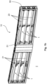
- FIGS 1a and 1b show a front view of a device 10 according to the invention, wherein in Figure 1a a closed position II is shown. It can be seen that in the closed position II, cover elements 20, 21 are closed and thus the entry of air through an opening 1 is at least partially prevented by the cover elements 20, 21.
- the opening 1 can, for example, be in the open position I in Figure 1b illustrated spaces of the device 10, so that when the cover elements 20, 21 are open, the air flow can be directed through the device 10. It is also conceivable that an air inlet area or a radiator grille of the vehicle immediately in front of the device 10 according to the invention is considered an opening 1.
- the opening 1 may have different opening areas, with each opening area being assigned at least one (and in the exemplary embodiment shown three) cover element(s) 20, 21.
- first cover elements 20 left side in the direction of the vehicle
- second cover elements 21 right side in the direction of the vehicle
- cover means 20.2, 21.2 cover means
- the covering means 20.2, 21.2 are impermeable to air and z. B. rigid, elastic or bendable e.g. B. designed as a slat, flap or roller blind in order to effect an airtight closure of the opening 1.
- All covering materials 20.2, 21.2 or Corresponding cover elements 20, 21 are arranged parallel to one another.
- the cover elements 20, 21 are rotatably mounted in a carrier 50.
- the cover elements 20, 21 can be transferred from a closed position II, in which the cover means 20.2, 21.2 close the opening 1 or prevent air from entering the vehicle, by a rotary movement in the carrier 50 into an open position I, in which the cover means 20.2 , 21.2 are arranged or rotated in such a way that air can enter through the opening 1.
- the open position I of the device 10 according to the invention is in Figure 1b shown.
- a central web 51 is also shown, which z. B. can be an integral part of the carrier 50, with a drive 30 being arranged behind the central web 51.
- the central web 51 can have at least one cooling opening 51.1 for the drive 30 in order to ensure sufficient cooling by fresh air, which is directed to the drive 30 through the cooling openings 51.1, and thus to ensure safe operation of the drive 30.
- the device 10 is z. B. in the front area of the vehicle, e.g. B. arranged in the (rear) area of a front end module of the vehicle.
- the front of the device 10 is aligned towards the outside of the vehicle or the front of the vehicle, so that when air enters through the device 10, the air is guided into the interior of the vehicle.
- the following directional information on the device 10 always corresponds to the vehicle directions (e.g. the front of the device 10 is aligned in the direction of travel and the back is aligned towards the interior of the vehicle).
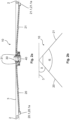
- FIG 2a and Figure 2b a top view of the device 10 according to the invention is shown, with first cover elements 20 being arranged on the left side of the device 10 or the vehicle and second cover elements 21 on the right side of the device 10 or the vehicle.
- the cover elements 20, 21 are connected in the middle via a driver 40.
- the driver 40 is simultaneously connected to the cover elements 20, 21 and to a drive 30 of the device 10 (indirectly) and is arranged in such a way that the driver 40 causes a movement of the drive 30 (in particular a drive shaft or drive receptacle 30.1 of the drive 30).
- the cover elements 20, 21 can be transferred.
- the drive receptacle 30.1 of the drive 30 is aligned with a drive shaft 31.2 of a connecting element 31 and is connected to the connecting element 31 in a rotationally fixed manner.
- the connecting element 31 is designed as a crank and z. B. be connected positively and/or non-positively to a second, in particular inner, fastening element 40.2 of the driver 40 via a latching or clip connection.
- the second fastening element 40.2 can be designed as a fastening pin be and be rotatably mounted in a force-fitting and/or form-fitting manner in the connecting element 31.
- the cover elements 20, 21 are arranged at an angle to one another, ie in particular the first cover elements 20 are arranged at an angle to the second cover elements 21.
- the cover elements 20, 21 (or their axis of rotation shown with a dashed line) have a deflection angle ⁇ .
- the cover elements 20, 21 are arranged at an angle to one another at an angle ⁇ , the angle ⁇ corresponding to twice the angle ⁇ . It is therefore necessary that the transmission of the movement of the drive 30 to the cover elements 20, 21 takes place at an angle, ie with an angular offset 2.
- the angled arrangement of the cover elements 20, 21 is in Figure 2b clearly.
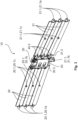
- FIG 3 a perspective rear view of parts of a device 10 according to the invention is shown, the carrier 50 not being shown.
- the device 10 according to the invention includes first cover elements 20 and second cover elements 21, bearing elements 20.1 of the first cover elements 20 and bearing elements 21.1 of the second cover elements 21 being shown.
- the driver 40 is connected centrally to the first cover elements 20 on one side (via receiving elements 20.3) and centrally to the cover elements 21 (via receiving elements 21.3) on an opposite side.
- a movement of the driver 40 in particular along a (partial) circular path (e.g. in a plane parallel to the direction of travel), is thus transmitted to both the first cover elements 20 and the second cover elements 21 through the driver 40.
- the first cover elements 21 are connected to each other via the driver 40 and second cover elements 22 are also connected to each other via the driver 40. Since the covering elements 20, 21, in particular the covering means 20.2, 21.2, are rotatably mounted in the carrier 50 via bearing elements 20.1, 21.1, the movement of the driver 40 along the circular path is converted into a rotary movement of the covering elements 20, 21 (or each individual covering means 20.2 , 21.2) implemented in the carrier 50.
- a single cover element 20, 21 thus comprises a cover means 20.2, 21.2 and at least two bearing elements 20.1, 21.1 on opposite sides.
- the individual first cover element 20 comprises a first or outer bearing element 20.1a and a second, inner bearing element 20.1b on the opposite side of the cover means 20.2 Cover element 20.
- the bearing elements 20.1, 21.1 include z. B. the outer bearing elements 20.1a, 21.1a, central bearing elements 20.1c, 21.1c and the inner bearing elements 20.1b, 21.1b.
- the inner bearing elements 20.1b, 21.1b serve for connection and storage on an inner bearing receptacle 50.1b of the carrier 50.
- Receiving elements 20.3 are also provided for connecting and / or guiding the cover elements 20, 21 on the driver 40, with fixing elements 40.3 of the driver 40 z. B. are designed as mushroom heads and are arranged such that a lateral movement (ie outwards) of the cover elements 20, 21 away from the driver 40 is prevented.
- a drive 30 is arranged behind the driver 40, which generates a mechanical (rotational) movement, whereby the driver 40 is moved and the cover elements 20, 21 are driven for a movement between the open position I and the closed position II.
- the driver 40 has cooling openings 40.5 to enable the drive 30 to be cooled.
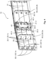
- Figure 4 shows an enlarged view of the device 10 according to the invention in a rear view.
- the cover elements 20, 21, in particular the cover means 20.2, 21.2 are rotatably mounted in the carrier 50.
- the cover elements 20, 21 have bearing elements 20.1, 21.1 connected to the cover means 20.2, 21.2.
- the bearing elements 20.1, 21.1 can z. B. be designed as a bearing pin and correspond to corresponding bearing receptacles 50.1 of the carrier 50.
- an outer bearing element 20.1a can be rotatably mounted and/or positively connected in an outer bearing receptacle 50.1a of the carrier 50.
- central bearing elements 20.1c, 21.1c of the cover elements 20, 21 are shown, which are connected to the cover means 20.2, 21.2 and are designed, for example, as a receiving element for supporting a bearing pin of support elements 50.2.
- a first support element 50.2a and a second support element 50.2b can be provided to support the first cover elements 20 and second cover elements 21 and each can be supported by central bearing elements 20.1c, 21.1c of the cover elements 20, 21.
- the support elements 50.2 enable improved storage of the cover elements 20, 21 in the carrier 50 and also prevent the cover elements 20, 21 and/or cover means 20.2, 21.2 from bending at high contact pressure due to the air inlet through the opening 1. Furthermore, in Figure 4 Receiving elements 20.3, 21.3 of the cover elements 20, 21 can be seen, which enable a non-positive and / or positive reception and / or rotatable mounting on the first or outer fastening elements 40.1 of the driver 40. Fixing elements 40.3 of the driver 40 are arranged in such a way that a lateral movement (ie outwards) of the cover elements 20, 21 or covering means 20.2, 21.2 away from the driver 40 is prevented.
- Figure 5 shows an enlarged view of parts of the device 10 according to the invention, in particular a drive 30, a driver 40 and a connecting element 31.
- the drive 30 has a drive receptacle 30.1, into which a drive shaft 31.2 of the connecting element 31 is inserted.
- the drive shaft 31.2 is z. B. non-rotatably, non-positively and / or positively connected to the drive receptacle 30.1 or arranged in the drive receptacle 30.1.
- the drive 30 can, for example, be designed to be self-locking, so that a movement or rotational movement of the connecting element 31 can only be caused by the drive 30.
- the driver 40 is in turn connected to the connecting element 31 and thus indirectly to the drive 30 by a fastening element, in particular a second fastening element 40.2.
- the movement of the connecting element 31 by the drive 30 leads the driver 40 into a movement, in particular into a circular path. Since the driver 40 is connected to the cover elements 20, 21 via fastening elements, in particular first or outer fastening elements 40.1, the movement of the drive 30 is transmitted to the cover elements 20, 21.
- the cover elements 20, 21 are rotatably mounted in the carrier 50 via bearing elements 20.1, 21.1, so that operation of the drive 30 causes the cover elements 20, 21 in the carrier 50 to rotate and thus the cover means 20.2, 21.2 are tilted, whereby an opening 1 is released becomes.
- Figure 5 in particular the inner bearing elements 20.1b, 21.1b of the cover elements 20, 21 and the bearing means 31.1 of the connecting element 31 are shown.
- the bearing elements 20.1b, 21.1b ensure that the cover elements 20, 21 are mounted in the carrier 50 or in a central web 51, not shown.
- the bearing means 31.1 are also rotatably mounted in the carrier 50 or in the central web 51.
- FIG. 6 a top view of parts of a device 10 according to the invention is shown.
- a drive 30 is shown, with a connecting element 31 being operated by the drive 30.
- a connecting element 31 being operated by the drive 30.
- a first cover element 20 is aligned at an angle ⁇ to the alignment of the drive 30 or the axis of the bearing means 31.1.
- the angular offset 2 essentially corresponds to the angle ⁇ .
- the driver 40 has a fastening element, in particular a second or inner fastening element 40.2, which is connected to the connecting element 31 or is rotatably mounted in the connecting element 31.
- the second (or inner) fastening element 40.2 is aligned essentially parallel to the orientation of the drive 30 or a drive receptacle 30.1 or the bearing means 31.1.
- the driver 40 has a further fastening element, in particular a first or outer fastening element 40.1, which is connected to the cover elements 20, 21 or in the cover elements 20, 21 (ie in at least one receiving element 20.3, 21.3 of the cover elements 20, 21). is rotatably mounted.
- the first (or outer) fastening element 40.1 is designed to be rigid and/or non-rotatably connected to the second or inner fastening element 40.2, so that a movement of the driver 40 affects both the second (inner) fastening element 40.2 and the first (outer) fastening element 40.1 regards.
- the second fastening element 40.2 has an orientation that is adapted to the orientation of the cover elements 20, 21 and essentially corresponds to the angular offset 2.
- FIG 7a and Figure 7b show a schematic rear view of a device 10 according to the invention, wherein in Figure 7a an open position I and Figure 7b a closed position II is shown.
- a drive 30 is arranged centrally between a first cover element 20 and a second cover element 21.
- the cover elements 20, 21 can z. B. be designed as a roller blind. In an open position I, the cover elements 20, 21 are therefore wound up and are brought into a closed position II by development. This is achieved by the movement of a drive 30, which z. B. transmits a rotary movement via a driver 40 to a shaft (for winding up the blinds) of the cover elements 20, 21.
- a rotation in a first direction causes the covering means 20.2, 21.2 to be wound up and a rotation in a second direction to develop, for example.
- B. have an elastic material and/or a textile.
- the driver 40 is designed as a joint 40.4, in particular as a cardan joint.
- FIG 8 A method 100 according to the invention is shown schematically, with the cover elements 20, 21 being in an open position I in a first method step 100.1. Subsequently, in the second method step 100.2, a movement of a drive 30 is transmitted at an angle to the cover elements 20, 21 via a driver 40. After a movement of the driver 40 along a circular path, the cover elements 20, 21 are in a closed position II in the third method step 100.3, in which case the entry of air through an opening 1 is at least partially prevented.
Landscapes
- Engineering & Computer Science (AREA)
- Chemical & Material Sciences (AREA)
- Combustion & Propulsion (AREA)
- Transportation (AREA)
- Mechanical Engineering (AREA)
- Cooling, Air Intake And Gas Exhaust, And Fuel Tank Arrangements In Propulsion Units (AREA)
- Air-Flow Control Members (AREA)
- Cooling Or The Like Of Electrical Apparatus (AREA)
Claims (13)
- Dispositif (10) pour réguler un flux d'air vers un dispositif de refroidissement d'un véhicule, le flux d'air pouvant être dirigé vers le dispositif de refroidissement à travers au moins une ouverture (1), avecau moins deux éléments de recouvrement (20, 21) pour fermer au moins partiellement l'ouverture (1) dans au moins une position de fermeture (II), etun entraînement (30) pour déplacer les éléments de recouvrement (20, 21) entre la position de fermeture (II) et une position d'ouverture (I) pour libérer au moins partiellement l'ouverture (1),un entraîneur (40) étant prévu pour transmettre un mouvement de l'entraînement (30) aux éléments de recouvrement (20, 21), et les éléments de recouvrement (20, 21) étant disposés de manière inclinée les uns par rapport aux autres,la transmission du mouvement par l'entraîneur (40) s'effectuant de manière inclinée, les éléments de recouvrement (20, 21) étant disposés de manière inclinée les uns par rapport aux autres sur un angle α, etla transmission du mouvement par l'entraîneur (40) suivant l'angle α entre les éléments de recouvrement (20, 21),et dans lequel deux éléments de liaison (31), à savoir deux manivelles, sont reliés à l'entraîneur (40) pour la liaison directe et/ou la transmission du mouvement de l'entraînement (30), etces deux éléments de liaison (31) étant respectivement reliés de manière solidaire en rotation à un arbre d'entraînement et/ou à un logement d'entraînement de l'entraînement (30), de sorte que lors d'un fonctionnement de l'entraînement (30), il se produit un mouvement de rotation des éléments de liaison (31).
- Dispositif (10) selon la revendication 1,
caractérisé en ce que
l'entraîneur (40) est réalisé de telle sorte que le mouvement, en particulier un mouvement de rotation de l'entraînement (30), est transmis par l'entraîneur (40) avec un décalage angulaire (2) aux au moins deux éléments de recouvrement (20, 21). - Dispositif (10) selon l'une des revendications précédentes,
caractérisé en ce que
l'entraîneur (40) présente au moins un premier élément de fixation (40.1), en particulier un tenon de fixation, pour la liaison avec les éléments de recouvrement (20, 21) et en particulier au moins un deuxième élément de fixation (40.2), en particulier un tenon de fixation, pour la liaison avec l'entraînement (30). - Dispositif (10) selon l'une des revendications précédentes,
caractérisé en ce que
l'entraîneur (40) est conçu comme une articulation (40.4), en particulier comme un joint de cardan. - Dispositif (10) selon l'une des revendications précédentes,
caractérisé en ce que
le flux de force pour la transmission du mouvement pour le déplacement des éléments de recouvrement (20, 21) entre la position de fermeture (II) et la position d'ouverture (I) est effectué par l'entraînement (30), en particulier exclusivement par l'intermédiaire de l'entraîneur (40) aux éléments de recouvrement (20, 21). - Dispositif (10) selon l'une des revendications précédentes,
caractérisé en ce qu'
au moins un composant situé dans le flux de force, en particulier l'entraîneur (40) et/ou le premier élément de fixation (40.1) et/ou le deuxième élément de fixation (40.2) de l'entraîneur (40), présente une surface bombée et/ou bombée et/ou coudée, qui est en particulier conçue de telle sorte que les tolérances lors d'un mouvement de rotation, en particulier des éléments de recouvrement (20, 21), des éléments de fixation et/ou de l'entraîneur (40), sont compensées. - Dispositif (10) selon l'une des revendications précédentes,
caractérisé en ce que
les éléments de recouvrement (20, 21) sont montés mobiles dans un support (50), au moins deux éléments de palier (20.1, 21.1) des éléments de recouvrement (20, 21) étant notamment montés rotatifs dans un logement de palier (50.1) respectif du support (50). - Dispositif (10) selon l'une des revendications précédentes,
caractérisé en ce qu'
au moins un élément de palier central (20.1c, 21.1c) des éléments de recouvrement (20, 21) est disposé au centre d'au moins un moyen de recouvrement (20.2, 21.2) des éléments de recouvrement (20, 21), et est conçu en particulier comme élément de réception pour un élément de support (50.2) du support (50). - Dispositif (10) selon l'une des revendications précédentes,
caractérisé en ce que
le support (50) et/ou les éléments de recouvrement (20, 21) et/ou l'entraîneur (40) sont réalisés d'une seule pièce, en particulier de manière monolithique, notamment à partir d'une pièce moulée par injection. - Dispositif (10) selon l'une des revendications précédentes,
caractérisé en ce que
chacune des deux manivelles, pour la liaison directe et/ou la transmission du mouvement d'un arbre d'entraînement et/ou d'un logement d'entraînement (30.1), est reliée à un deuxième élément de fixation (40.2). - Dispositif (10) selon l'une des revendications précédentes,
caractérisé en ce que
l'entraîneur (40) est relié directement aux éléments de recouvrement (20, 21) par l'intermédiaire d'au moins un premier élément de fixation (40.1), en particulier par adhérence et/ou par complémentarité de forme avec un élément de réception (20.3, 21.3) des éléments de recouvrement (20, 21), en particulier de telle sorte que, lors d'un mouvement de l'entraîneur (40), il se produit une rotation des éléments de recouvrement (20, 21) entre la position d'ouverture (I) et la position de fermeture (II). - Dispositif (10) selon l'une des revendications précédentes,
caractérisé en ce qu'
au moins un élément de fixation (40.3) de l'entraîneur (40) est disposé sur le premier élément de fixation (40.1) de telle sorte qu'un mouvement latéral des éléments de recouvrement (20, 21) est bloqué. - Procédé (100) de fonctionnement d'un dispositif (10) pour réguler un flux d'air vers un dispositif de refroidissement d'un véhicule, dans lequel
le flux d'air est dirigé vers le dispositif de refroidissement à travers au moins une ouverture (1), avec
au moins deux éléments de couverture (20, 21), dans lesquels
les éléments de couverture (20, 21) ferment au moins partiellement l'ouverture (1) dans au moins une position de fermeture (II), et
dans une position d'ouverture (I), ils libèrent au moins partiellement l'ouverture (1), où le mouvement des éléments de recouvrement (20, 21) entre la position de fermeture (II) et la position d'ouverture (I) est effectué par un entraînement (30), où les éléments de recouvrement (20, 21) sont disposés de manière inclinée et le mouvement de l'entraînement (30) est transmis aux éléments de recouvrement (20, 21) par l'intermédiaire d'un entraîneur (40), un dispositif (10) selon l'une des revendications 1 à 12 étant mis en oeuvre.
Applications Claiming Priority (2)
| Application Number | Priority Date | Filing Date | Title |
|---|---|---|---|
| DE102014117816.5A DE102014117816A1 (de) | 2014-12-03 | 2014-12-03 | Optimiertes Luftregelsystem für Fahrzeuge |
| PCT/EP2015/078480 WO2016087567A1 (fr) | 2014-12-03 | 2015-12-03 | Système de régulation pneumatique optimisé pour véhicules |
Publications (2)
| Publication Number | Publication Date |
|---|---|
| EP3227135A1 EP3227135A1 (fr) | 2017-10-11 |
| EP3227135B1 true EP3227135B1 (fr) | 2023-09-20 |
Family
ID=54843811
Family Applications (1)
| Application Number | Title | Priority Date | Filing Date |
|---|---|---|---|
| EP15807836.0A Active EP3227135B1 (fr) | 2014-12-03 | 2015-12-03 | Système de régulation pneumatique optimisé pour véhicules |
Country Status (7)
| Country | Link |
|---|---|
| US (1) | US10391857B2 (fr) |
| EP (1) | EP3227135B1 (fr) |
| CN (1) | CN107000575B (fr) |
| DE (1) | DE102014117816A1 (fr) |
| ES (1) | ES2964783T3 (fr) |
| MX (1) | MX380347B (fr) |
| WO (1) | WO2016087567A1 (fr) |
Cited By (1)
| Publication number | Priority date | Publication date | Assignee | Title |
|---|---|---|---|---|
| US20240174077A1 (en) * | 2022-11-28 | 2024-05-30 | Valeo Systemes Thermiques | Active grille shutter system |
Families Citing this family (19)
| Publication number | Priority date | Publication date | Assignee | Title |
|---|---|---|---|---|
| US9956866B2 (en) * | 2015-10-16 | 2018-05-01 | Flex-N-Gate Advanced Product Development, Llc | Active grille shutter |
| ES2676754T3 (es) * | 2015-12-07 | 2018-07-24 | Flex-N-Gate France | Cuerpo de un vehículo de motor que comprende obturadores con separadores y vehículo asociado |
| FR3061876B1 (fr) * | 2017-01-18 | 2024-10-25 | Valeo Systemes Thermiques | Dispositif d’obturation d’entree d’air de face avant de vehicule automobile et procede de fabrication |
| FR3062606B1 (fr) * | 2017-02-06 | 2019-04-19 | Valeo Systemes Thermiques | Dispositif d'obturation d'entree d'air de face avant de vehicule automobile |
| FR3068304B1 (fr) * | 2017-06-29 | 2019-07-19 | Valeo Systemes Thermiques | Dispositif d'obturation d'entree d'air de face avant de vehicule automobile |
| US10093173B1 (en) * | 2017-07-26 | 2018-10-09 | Srg Global Inc. | Active grille shutter system with louver compensation feature |
| FR3069494B1 (fr) * | 2017-07-28 | 2019-08-02 | Valeo Systemes Thermiques | Dispositif d'obturation d'entree d'air de vehicule automobile et procede de fabrication d'un tel dispositif d'obturation |
| JP6922654B2 (ja) * | 2017-10-27 | 2021-08-18 | 豊田合成株式会社 | 車両用グリルシャッタ装置 |
| CN108705929A (zh) * | 2018-05-25 | 2018-10-26 | 江苏派欧汽车零部件有限公司 | 一种汽车用进气口导风罩 |
| DE102018004361A1 (de) * | 2018-06-01 | 2019-12-05 | Psa Automobiles Sa | Jalousie zur variablen Abdeckung mindestens eines Kühlers eines Kraftfahrzeugs |
| DE102018208747A1 (de) * | 2018-06-04 | 2019-12-05 | Röchling Automotive SE & Co. KG | Montage-Spritzgussverfahren zur Herstellung einer Kfz-Luftklappenvorrichtung |
| EP3802187B1 (fr) | 2018-06-05 | 2025-01-08 | Magna Exteriors Inc. | Système d'actionnement fonctionnel pour volet à grille active |
| FR3093033B1 (fr) * | 2019-02-26 | 2022-08-26 | Flex N Gate France | Dispositif d’aération pour un véhicule |
| DE102019106828B4 (de) * | 2019-03-18 | 2022-06-23 | Hbpo Gmbh | Vorrichtung zum Verschließen eines Kraftfahrzeugkühlmoduls |
| FR3094674B1 (fr) * | 2019-04-03 | 2021-04-16 | Flex N Gate France | Dispositif d’aération pour un véhicule, procédé de montage associé |
| DE102019117986B4 (de) * | 2019-07-03 | 2021-06-24 | Hbpo Gmbh | Vorrichtung zum Verschließen eines Kraftfahrzeugkühlmoduls |
| DE102021103785A1 (de) * | 2021-02-17 | 2022-08-18 | Röchling Automotive Se & Co.Kg | Zur Onboard-Diagnose ausgebildete Luftklappenanordnung für ein Kraftfahrzeug |
| US11845331B2 (en) | 2022-03-03 | 2023-12-19 | Valeo Systemes Thermiques | Air flow control device for a front face module of a motor vehicle |
| US12583292B2 (en) * | 2023-07-26 | 2026-03-24 | Valeo Systemes Thermiques | Driving vane for an active grille shutter device |
Citations (4)
| Publication number | Priority date | Publication date | Assignee | Title |
|---|---|---|---|---|
| US20120012410A1 (en) * | 2010-07-13 | 2012-01-19 | Aisin Seiki Kabushiki Kaisha | Movable grille shutter for vehicle |
| DE102011078691A1 (de) * | 2011-07-05 | 2013-01-10 | Röchling Automotive AG & Co. KG | Luftleiteinrichtung für ein Kraftfahrzeug |
| JP2013199178A (ja) * | 2012-03-23 | 2013-10-03 | Faltec Co Ltd | 車両用グリルシャッタ |
| DE102014108575A1 (de) * | 2014-06-18 | 2014-11-06 | Dr. Ing. H.C. F. Porsche Aktiengesellschaft | Kühlerjalousieanordnung |
Family Cites Families (13)
| Publication number | Priority date | Publication date | Assignee | Title |
|---|---|---|---|---|
| DE3731980C1 (de) * | 1987-09-23 | 1989-03-23 | Freudenberg Carl Fa | Jalousie zum bedarfsweisen Verschliessen einer durchstroembaren OEffnung |
| DE102004056328A1 (de) * | 2004-11-22 | 2006-06-08 | Behr Gmbh & Co. Kg | Vorrichtung zur Regulierung eines Luftstroms zur Motorkühlung und Verfahren zur Herstellung einer Faltklappe |
| DE102009020352A1 (de) * | 2009-05-07 | 2010-11-11 | Dr. Ing. H.C. F. Porsche Aktiengesellschaft | Aufnahmevorrichtung für ein Kühlluftklappenmodul in einer Bugverkleidung eines Kraftfahrzeugs |
| KR101163447B1 (ko) * | 2009-09-30 | 2012-07-18 | 주식회사 에스에이치비 | 자동차용 에어플랩 개폐장치 |
| US8708078B2 (en) | 2010-04-13 | 2014-04-29 | GM Global Technology Operations LLC | Flexible drive element for an angled active shutter |
| JP5862033B2 (ja) * | 2010-07-13 | 2016-02-16 | アイシン精機株式会社 | 車両用可動グリルシャッター |
| US8646552B2 (en) * | 2010-07-21 | 2014-02-11 | Shape Corp. | Integrated energy absorber and air flow management structure |
| KR101261516B1 (ko) * | 2011-04-06 | 2013-05-06 | 토마토에이엔피(주) | 에어플랩을 구비한 라디에이터 그릴 |
| DE102011103585B4 (de) * | 2011-05-30 | 2022-06-15 | Mercedes-Benz Group AG | Kühlergrillanordnung |
| US8720624B2 (en) * | 2012-04-10 | 2014-05-13 | GM Global Technology Operations LLC | Angled active shutter with dual-drive actuation |
| US10029558B2 (en) | 2013-03-15 | 2018-07-24 | Srg Global, Inc. | Grille shutter assembly |
| GB2512071A (en) * | 2013-03-19 | 2014-09-24 | Johnson Electric Sa | Grille shutter actuator |
| KR101532976B1 (ko) * | 2014-09-01 | 2015-07-01 | 현대모비스 주식회사 | 차량용 에어 플랩 장치 |
-
2014
- 2014-12-03 DE DE102014117816.5A patent/DE102014117816A1/de not_active Ceased
-
2015
- 2015-12-03 ES ES15807836T patent/ES2964783T3/es active Active
- 2015-12-03 CN CN201580058261.1A patent/CN107000575B/zh active Active
- 2015-12-03 EP EP15807836.0A patent/EP3227135B1/fr active Active
- 2015-12-03 US US15/533,274 patent/US10391857B2/en active Active
- 2015-12-03 MX MX2017005003A patent/MX380347B/es unknown
- 2015-12-03 WO PCT/EP2015/078480 patent/WO2016087567A1/fr not_active Ceased
Patent Citations (4)
| Publication number | Priority date | Publication date | Assignee | Title |
|---|---|---|---|---|
| US20120012410A1 (en) * | 2010-07-13 | 2012-01-19 | Aisin Seiki Kabushiki Kaisha | Movable grille shutter for vehicle |
| DE102011078691A1 (de) * | 2011-07-05 | 2013-01-10 | Röchling Automotive AG & Co. KG | Luftleiteinrichtung für ein Kraftfahrzeug |
| JP2013199178A (ja) * | 2012-03-23 | 2013-10-03 | Faltec Co Ltd | 車両用グリルシャッタ |
| DE102014108575A1 (de) * | 2014-06-18 | 2014-11-06 | Dr. Ing. H.C. F. Porsche Aktiengesellschaft | Kühlerjalousieanordnung |
Cited By (1)
| Publication number | Priority date | Publication date | Assignee | Title |
|---|---|---|---|---|
| US20240174077A1 (en) * | 2022-11-28 | 2024-05-30 | Valeo Systemes Thermiques | Active grille shutter system |
Also Published As
| Publication number | Publication date |
|---|---|
| MX380347B (es) | 2025-03-12 |
| CN107000575A (zh) | 2017-08-01 |
| US10391857B2 (en) | 2019-08-27 |
| US20170326970A1 (en) | 2017-11-16 |
| CN107000575B (zh) | 2020-07-03 |
| ES2964783T3 (es) | 2024-04-09 |
| EP3227135A1 (fr) | 2017-10-11 |
| MX2017005003A (es) | 2017-06-30 |
| WO2016087567A1 (fr) | 2016-06-09 |
| DE102014117816A1 (de) | 2016-06-09 |
Similar Documents
| Publication | Publication Date | Title |
|---|---|---|
| EP3227135B1 (fr) | Système de régulation pneumatique optimisé pour véhicules | |
| EP3227134B1 (fr) | Dispositif de régulation d'un flux d'air pour véhicule et procédé de montage | |
| DE102019108990B4 (de) | Sequentielle Lamellenjalousieschaltung | |
| EP2113419B1 (fr) | Dispositif de recouvrement pour l'espace intérieur d'un véhicule | |
| DE102011103585B4 (de) | Kühlergrillanordnung | |
| EP2119619B1 (fr) | Véhicule automobile avec dispositif aérodynamique retractable | |
| EP2326525A1 (fr) | Dispoisitif grille de refroidissement | |
| DE112006000764T5 (de) | Anzeigevorrichtung | |
| DE102019114940A1 (de) | Scharnierbasierter Ausgleichsmechanismus | |
| DE102020125917B4 (de) | Luftführungssteuerung für einen Verbrennungsmotor | |
| WO2020234031A1 (fr) | Unité de sortie d'air pour l'aération d'un véhicule et véhicule | |
| WO2018108369A1 (fr) | Structure de clapet de ventilation pour un module de climatisation de véhicule automobile | |
| EP1716013A1 (fr) | Dispositif pour actionner au moins un element exterieur pivotant d'un vehicule | |
| DE102015109229A1 (de) | Abdeckelement zum Regulieren einer Luftströmung zu einer Kühlervorrichtung | |
| DE102008012434A1 (de) | Modulbaugruppe zum Einbau in ein Kraftfahrzeug | |
| DE102015000752A1 (de) | Rolloeinrichtung für eine Seitenscheibe eines Kraftfahrzeugs | |
| DE69810380T2 (de) | Türschliesser, damit ausgerüstete Tür und Schienenfahrzeug mit mindestens einer derartigen Vorrichtung und/oder Tür | |
| WO2019030137A1 (fr) | Système de commande pour lève-vitre | |
| DE102013202801B4 (de) | Einrichtung zur motorischen Betätigung einer Kraftfahrzeug-Türe mit Feststellfunktion | |
| EP4206016B1 (fr) | Interface de chargement pour un véhicule, comprenant une boîte de chargement, un hayon de véhicule et un dispositif d'entraînement | |
| DE102023204091B3 (de) | Verschlusssystem | |
| EP3919301B1 (fr) | Dispositif de store roulant et procédé de montage d'un dispositif de store roulant | |
| DE102021211435B4 (de) | Kühlerverschlussvorrichtung mit mindestens einem zwischen einer Offenstellung und einer Schließstellung durch Auf- und Abwickeln verfahrbaren Verschlusselement für ein Kühlermodul oder für einen Kühlergrill eines Fahrzeuges | |
| WO2017182475A1 (fr) | Ensemble comprenant un vantail de porte et un mécanisme de commande pour mouvoir le vantail de porte, destiné à un véhicule de transport de passagers | |
| EP1908906A2 (fr) | Dispositif d'entraînement d'une porte coulissante de voiture |
Legal Events
| Date | Code | Title | Description |
|---|---|---|---|
| STAA | Information on the status of an ep patent application or granted ep patent |
Free format text: STATUS: THE INTERNATIONAL PUBLICATION HAS BEEN MADE |
|
| PUAI | Public reference made under article 153(3) epc to a published international application that has entered the european phase |
Free format text: ORIGINAL CODE: 0009012 |
|
| STAA | Information on the status of an ep patent application or granted ep patent |
Free format text: STATUS: REQUEST FOR EXAMINATION WAS MADE |
|
| 17P | Request for examination filed |
Effective date: 20170703 |
|
| AK | Designated contracting states |
Kind code of ref document: A1 Designated state(s): AL AT BE BG CH CY CZ DE DK EE ES FI FR GB GR HR HU IE IS IT LI LT LU LV MC MK MT NL NO PL PT RO RS SE SI SK SM TR |
|
| AX | Request for extension of the european patent |
Extension state: BA ME |
|
| RIN1 | Information on inventor provided before grant (corrected) |
Inventor name: SCHOENING, RALF |
|
| DAV | Request for validation of the european patent (deleted) | ||
| DAX | Request for extension of the european patent (deleted) | ||
| STAA | Information on the status of an ep patent application or granted ep patent |
Free format text: STATUS: EXAMINATION IS IN PROGRESS |
|
| 17Q | First examination report despatched |
Effective date: 20180517 |
|
| PUAG | Search results despatched under rule 164(2) epc together with communication from examining division |
Free format text: ORIGINAL CODE: 0009017 |
|
| B565 | Issuance of search results under rule 164(2) epc |
Effective date: 20210607 |
|
| RIC1 | Information provided on ipc code assigned before grant |
Ipc: B60K 11/08 20060101AFI20210601BHEP |
|
| GRAP | Despatch of communication of intention to grant a patent |
Free format text: ORIGINAL CODE: EPIDOSNIGR1 |
|
| STAA | Information on the status of an ep patent application or granted ep patent |
Free format text: STATUS: GRANT OF PATENT IS INTENDED |
|
| INTG | Intention to grant announced |
Effective date: 20221109 |
|
| GRAJ | Information related to disapproval of communication of intention to grant by the applicant or resumption of examination proceedings by the epo deleted |
Free format text: ORIGINAL CODE: EPIDOSDIGR1 |
|
| STAA | Information on the status of an ep patent application or granted ep patent |
Free format text: STATUS: EXAMINATION IS IN PROGRESS |
|
| INTC | Intention to grant announced (deleted) | ||
| GRAP | Despatch of communication of intention to grant a patent |
Free format text: ORIGINAL CODE: EPIDOSNIGR1 |
|
| STAA | Information on the status of an ep patent application or granted ep patent |
Free format text: STATUS: GRANT OF PATENT IS INTENDED |
|
| INTG | Intention to grant announced |
Effective date: 20230512 |
|
| P01 | Opt-out of the competence of the unified patent court (upc) registered |
Effective date: 20230606 |
|
| GRAS | Grant fee paid |
Free format text: ORIGINAL CODE: EPIDOSNIGR3 |
|
| GRAA | (expected) grant |
Free format text: ORIGINAL CODE: 0009210 |
|
| STAA | Information on the status of an ep patent application or granted ep patent |
Free format text: STATUS: THE PATENT HAS BEEN GRANTED |
|
| AK | Designated contracting states |
Kind code of ref document: B1 Designated state(s): AL AT BE BG CH CY CZ DE DK EE ES FI FR GB GR HR HU IE IS IT LI LT LU LV MC MK MT NL NO PL PT RO RS SE SI SK SM TR |
|
| REG | Reference to a national code |
Ref country code: GB Ref legal event code: FG4D Free format text: NOT ENGLISH |
|
| REG | Reference to a national code |
Ref country code: CH Ref legal event code: EP |
|
| REG | Reference to a national code |
Ref country code: IE Ref legal event code: FG4D Free format text: LANGUAGE OF EP DOCUMENT: GERMAN |
|
| REG | Reference to a national code |
Ref country code: DE Ref legal event code: R096 Ref document number: 502015016604 Country of ref document: DE |
|
| REG | Reference to a national code |
Ref country code: LT Ref legal event code: MG9D |
|
| PG25 | Lapsed in a contracting state [announced via postgrant information from national office to epo] |
Ref country code: GR Free format text: LAPSE BECAUSE OF FAILURE TO SUBMIT A TRANSLATION OF THE DESCRIPTION OR TO PAY THE FEE WITHIN THE PRESCRIBED TIME-LIMIT Effective date: 20231221 |
|
| REG | Reference to a national code |
Ref country code: NL Ref legal event code: MP Effective date: 20230920 |
|
| PG25 | Lapsed in a contracting state [announced via postgrant information from national office to epo] |
Ref country code: SE Free format text: LAPSE BECAUSE OF FAILURE TO SUBMIT A TRANSLATION OF THE DESCRIPTION OR TO PAY THE FEE WITHIN THE PRESCRIBED TIME-LIMIT Effective date: 20230920 Ref country code: RS Free format text: LAPSE BECAUSE OF FAILURE TO SUBMIT A TRANSLATION OF THE DESCRIPTION OR TO PAY THE FEE WITHIN THE PRESCRIBED TIME-LIMIT Effective date: 20230920 Ref country code: NO Free format text: LAPSE BECAUSE OF FAILURE TO SUBMIT A TRANSLATION OF THE DESCRIPTION OR TO PAY THE FEE WITHIN THE PRESCRIBED TIME-LIMIT Effective date: 20231220 Ref country code: LV Free format text: LAPSE BECAUSE OF FAILURE TO SUBMIT A TRANSLATION OF THE DESCRIPTION OR TO PAY THE FEE WITHIN THE PRESCRIBED TIME-LIMIT Effective date: 20230920 Ref country code: LT Free format text: LAPSE BECAUSE OF FAILURE TO SUBMIT A TRANSLATION OF THE DESCRIPTION OR TO PAY THE FEE WITHIN THE PRESCRIBED TIME-LIMIT Effective date: 20230920 Ref country code: HR Free format text: LAPSE BECAUSE OF FAILURE TO SUBMIT A TRANSLATION OF THE DESCRIPTION OR TO PAY THE FEE WITHIN THE PRESCRIBED TIME-LIMIT Effective date: 20230920 Ref country code: GR Free format text: LAPSE BECAUSE OF FAILURE TO SUBMIT A TRANSLATION OF THE DESCRIPTION OR TO PAY THE FEE WITHIN THE PRESCRIBED TIME-LIMIT Effective date: 20231221 Ref country code: FI Free format text: LAPSE BECAUSE OF FAILURE TO SUBMIT A TRANSLATION OF THE DESCRIPTION OR TO PAY THE FEE WITHIN THE PRESCRIBED TIME-LIMIT Effective date: 20230920 |
|
| PGFP | Annual fee paid to national office [announced via postgrant information from national office to epo] |
Ref country code: FR Payment date: 20231219 Year of fee payment: 9 |
|
| PG25 | Lapsed in a contracting state [announced via postgrant information from national office to epo] |
Ref country code: NL Free format text: LAPSE BECAUSE OF FAILURE TO SUBMIT A TRANSLATION OF THE DESCRIPTION OR TO PAY THE FEE WITHIN THE PRESCRIBED TIME-LIMIT Effective date: 20230920 |
|
| PG25 | Lapsed in a contracting state [announced via postgrant information from national office to epo] |
Ref country code: IS Free format text: LAPSE BECAUSE OF FAILURE TO SUBMIT A TRANSLATION OF THE DESCRIPTION OR TO PAY THE FEE WITHIN THE PRESCRIBED TIME-LIMIT Effective date: 20240120 |
|
| REG | Reference to a national code |
Ref country code: ES Ref legal event code: FG2A Ref document number: 2964783 Country of ref document: ES Kind code of ref document: T3 Effective date: 20240409 |
|
| PGFP | Annual fee paid to national office [announced via postgrant information from national office to epo] |
Ref country code: ES Payment date: 20240118 Year of fee payment: 9 |
|
| PG25 | Lapsed in a contracting state [announced via postgrant information from national office to epo] |
Ref country code: SM Free format text: LAPSE BECAUSE OF FAILURE TO SUBMIT A TRANSLATION OF THE DESCRIPTION OR TO PAY THE FEE WITHIN THE PRESCRIBED TIME-LIMIT Effective date: 20230920 Ref country code: RO Free format text: LAPSE BECAUSE OF FAILURE TO SUBMIT A TRANSLATION OF THE DESCRIPTION OR TO PAY THE FEE WITHIN THE PRESCRIBED TIME-LIMIT Effective date: 20230920 Ref country code: IS Free format text: LAPSE BECAUSE OF FAILURE TO SUBMIT A TRANSLATION OF THE DESCRIPTION OR TO PAY THE FEE WITHIN THE PRESCRIBED TIME-LIMIT Effective date: 20240120 Ref country code: EE Free format text: LAPSE BECAUSE OF FAILURE TO SUBMIT A TRANSLATION OF THE DESCRIPTION OR TO PAY THE FEE WITHIN THE PRESCRIBED TIME-LIMIT Effective date: 20230920 Ref country code: SK Free format text: LAPSE BECAUSE OF FAILURE TO SUBMIT A TRANSLATION OF THE DESCRIPTION OR TO PAY THE FEE WITHIN THE PRESCRIBED TIME-LIMIT Effective date: 20230920 Ref country code: PT Free format text: LAPSE BECAUSE OF FAILURE TO SUBMIT A TRANSLATION OF THE DESCRIPTION OR TO PAY THE FEE WITHIN THE PRESCRIBED TIME-LIMIT Effective date: 20240122 |
|
| PG25 | Lapsed in a contracting state [announced via postgrant information from national office to epo] |
Ref country code: PL Free format text: LAPSE BECAUSE OF FAILURE TO SUBMIT A TRANSLATION OF THE DESCRIPTION OR TO PAY THE FEE WITHIN THE PRESCRIBED TIME-LIMIT Effective date: 20230920 Ref country code: IT Free format text: LAPSE BECAUSE OF FAILURE TO SUBMIT A TRANSLATION OF THE DESCRIPTION OR TO PAY THE FEE WITHIN THE PRESCRIBED TIME-LIMIT Effective date: 20230920 |
|
| REG | Reference to a national code |
Ref country code: DE Ref legal event code: R097 Ref document number: 502015016604 Country of ref document: DE |
|
| PG25 | Lapsed in a contracting state [announced via postgrant information from national office to epo] |
Ref country code: DK Free format text: LAPSE BECAUSE OF FAILURE TO SUBMIT A TRANSLATION OF THE DESCRIPTION OR TO PAY THE FEE WITHIN THE PRESCRIBED TIME-LIMIT Effective date: 20230920 |
|
| PLBE | No opposition filed within time limit |
Free format text: ORIGINAL CODE: 0009261 |
|
| STAA | Information on the status of an ep patent application or granted ep patent |
Free format text: STATUS: NO OPPOSITION FILED WITHIN TIME LIMIT |
|
| PG25 | Lapsed in a contracting state [announced via postgrant information from national office to epo] |
Ref country code: DK Free format text: LAPSE BECAUSE OF FAILURE TO SUBMIT A TRANSLATION OF THE DESCRIPTION OR TO PAY THE FEE WITHIN THE PRESCRIBED TIME-LIMIT Effective date: 20230920 |
|
| REG | Reference to a national code |
Ref country code: CH Ref legal event code: PL |
|
| PG25 | Lapsed in a contracting state [announced via postgrant information from national office to epo] |
Ref country code: LU Free format text: LAPSE BECAUSE OF NON-PAYMENT OF DUE FEES Effective date: 20231203 |
|
| PG25 | Lapsed in a contracting state [announced via postgrant information from national office to epo] |
Ref country code: MC Free format text: LAPSE BECAUSE OF FAILURE TO SUBMIT A TRANSLATION OF THE DESCRIPTION OR TO PAY THE FEE WITHIN THE PRESCRIBED TIME-LIMIT Effective date: 20230920 |
|
| 26N | No opposition filed |
Effective date: 20240621 |
|
| GBPC | Gb: european patent ceased through non-payment of renewal fee |
Effective date: 20231220 |
|
| REG | Reference to a national code |
Ref country code: BE Ref legal event code: MM Effective date: 20231231 |
|
| PG25 | Lapsed in a contracting state [announced via postgrant information from national office to epo] |
Ref country code: MC Free format text: LAPSE BECAUSE OF FAILURE TO SUBMIT A TRANSLATION OF THE DESCRIPTION OR TO PAY THE FEE WITHIN THE PRESCRIBED TIME-LIMIT Effective date: 20230920 Ref country code: LU Free format text: LAPSE BECAUSE OF NON-PAYMENT OF DUE FEES Effective date: 20231203 |
|
| REG | Reference to a national code |
Ref country code: IE Ref legal event code: MM4A |
|
| PG25 | Lapsed in a contracting state [announced via postgrant information from national office to epo] |
Ref country code: IE Free format text: LAPSE BECAUSE OF NON-PAYMENT OF DUE FEES Effective date: 20231203 |
|
| PG25 | Lapsed in a contracting state [announced via postgrant information from national office to epo] |
Ref country code: GB Free format text: LAPSE BECAUSE OF NON-PAYMENT OF DUE FEES Effective date: 20231220 |
|
| PG25 | Lapsed in a contracting state [announced via postgrant information from national office to epo] |
Ref country code: BE Free format text: LAPSE BECAUSE OF NON-PAYMENT OF DUE FEES Effective date: 20231231 |
|
| PG25 | Lapsed in a contracting state [announced via postgrant information from national office to epo] |
Ref country code: CH Free format text: LAPSE BECAUSE OF NON-PAYMENT OF DUE FEES Effective date: 20231231 |
|
| PG25 | Lapsed in a contracting state [announced via postgrant information from national office to epo] |
Ref country code: SI Free format text: LAPSE BECAUSE OF FAILURE TO SUBMIT A TRANSLATION OF THE DESCRIPTION OR TO PAY THE FEE WITHIN THE PRESCRIBED TIME-LIMIT Effective date: 20230920 |
|
| PG25 | Lapsed in a contracting state [announced via postgrant information from national office to epo] |
Ref country code: SI Free format text: LAPSE BECAUSE OF FAILURE TO SUBMIT A TRANSLATION OF THE DESCRIPTION OR TO PAY THE FEE WITHIN THE PRESCRIBED TIME-LIMIT Effective date: 20230920 Ref country code: IE Free format text: LAPSE BECAUSE OF NON-PAYMENT OF DUE FEES Effective date: 20231203 Ref country code: GB Free format text: LAPSE BECAUSE OF NON-PAYMENT OF DUE FEES Effective date: 20231220 Ref country code: CH Free format text: LAPSE BECAUSE OF NON-PAYMENT OF DUE FEES Effective date: 20231231 Ref country code: BE Free format text: LAPSE BECAUSE OF NON-PAYMENT OF DUE FEES Effective date: 20231231 |
|
| PG25 | Lapsed in a contracting state [announced via postgrant information from national office to epo] |
Ref country code: BG Free format text: LAPSE BECAUSE OF FAILURE TO SUBMIT A TRANSLATION OF THE DESCRIPTION OR TO PAY THE FEE WITHIN THE PRESCRIBED TIME-LIMIT Effective date: 20230920 |
|
| PG25 | Lapsed in a contracting state [announced via postgrant information from national office to epo] |
Ref country code: BG Free format text: LAPSE BECAUSE OF FAILURE TO SUBMIT A TRANSLATION OF THE DESCRIPTION OR TO PAY THE FEE WITHIN THE PRESCRIBED TIME-LIMIT Effective date: 20230920 |
|
| REG | Reference to a national code |
Ref country code: AT Ref legal event code: MM01 Ref document number: 1613180 Country of ref document: AT Kind code of ref document: T Effective date: 20231203 |
|
| PG25 | Lapsed in a contracting state [announced via postgrant information from national office to epo] |
Ref country code: AT Free format text: LAPSE BECAUSE OF NON-PAYMENT OF DUE FEES Effective date: 20231203 |
|
| PG25 | Lapsed in a contracting state [announced via postgrant information from national office to epo] |
Ref country code: CY Free format text: LAPSE BECAUSE OF FAILURE TO SUBMIT A TRANSLATION OF THE DESCRIPTION OR TO PAY THE FEE WITHIN THE PRESCRIBED TIME-LIMIT; INVALID AB INITIO Effective date: 20151203 |
|
| PG25 | Lapsed in a contracting state [announced via postgrant information from national office to epo] |
Ref country code: HU Free format text: LAPSE BECAUSE OF FAILURE TO SUBMIT A TRANSLATION OF THE DESCRIPTION OR TO PAY THE FEE WITHIN THE PRESCRIBED TIME-LIMIT; INVALID AB INITIO Effective date: 20151203 |
|
| PG25 | Lapsed in a contracting state [announced via postgrant information from national office to epo] |
Ref country code: FR Free format text: LAPSE BECAUSE OF NON-PAYMENT OF DUE FEES Effective date: 20241231 |
|
| PG25 | Lapsed in a contracting state [announced via postgrant information from national office to epo] |
Ref country code: TR Free format text: LAPSE BECAUSE OF FAILURE TO SUBMIT A TRANSLATION OF THE DESCRIPTION OR TO PAY THE FEE WITHIN THE PRESCRIBED TIME-LIMIT Effective date: 20230920 |
|
| PGFP | Annual fee paid to national office [announced via postgrant information from national office to epo] |
Ref country code: CZ Payment date: 20251124 Year of fee payment: 11 |
|
| REG | Reference to a national code |
Ref country code: ES Ref legal event code: FD2A Effective date: 20260127 |
|
| PG25 | Lapsed in a contracting state [announced via postgrant information from national office to epo] |
Ref country code: ES Free format text: LAPSE BECAUSE OF NON-PAYMENT OF DUE FEES Effective date: 20241204 |
|
| PGFP | Annual fee paid to national office [announced via postgrant information from national office to epo] |
Ref country code: DE Payment date: 20251231 Year of fee payment: 11 |