EP3226237B1 - Beschallungseinrichtung - Google Patents
Beschallungseinrichtung Download PDFInfo
- Publication number
- EP3226237B1 EP3226237B1 EP17160914.2A EP17160914A EP3226237B1 EP 3226237 B1 EP3226237 B1 EP 3226237B1 EP 17160914 A EP17160914 A EP 17160914A EP 3226237 B1 EP3226237 B1 EP 3226237B1
- Authority
- EP
- European Patent Office
- Prior art keywords
- sound
- opening
- public address
- address system
- horn
- Prior art date
- Legal status (The legal status is an assumption and is not a legal conclusion. Google has not performed a legal analysis and makes no representation as to the accuracy of the status listed.)
- Active
Links
Images


Classifications
-
- G—PHYSICS
- G10—MUSICAL INSTRUMENTS; ACOUSTICS
- G10K—SOUND-PRODUCING DEVICES; METHODS OR DEVICES FOR PROTECTING AGAINST, OR FOR DAMPING, NOISE OR OTHER ACOUSTIC WAVES IN GENERAL; ACOUSTICS NOT OTHERWISE PROVIDED FOR
- G10K11/00—Methods or devices for transmitting, conducting or directing sound in general; Methods or devices for protecting against, or for damping, noise or other acoustic waves in general
- G10K11/02—Mechanical acoustic impedances; Impedance matching, e.g. by horns; Acoustic resonators
- G10K11/025—Mechanical acoustic impedances; Impedance matching, e.g. by horns; Acoustic resonators horns for impedance matching
-
- G—PHYSICS
- G10—MUSICAL INSTRUMENTS; ACOUSTICS
- G10K—SOUND-PRODUCING DEVICES; METHODS OR DEVICES FOR PROTECTING AGAINST, OR FOR DAMPING, NOISE OR OTHER ACOUSTIC WAVES IN GENERAL; ACOUSTICS NOT OTHERWISE PROVIDED FOR
- G10K13/00—Cones, diaphragms, or the like, for emitting or receiving sound in general
Definitions
- the present invention relates to a sound system with a sound generator, which has a main direction of radiation, and with a horn in the form of a funnel-shaped widening hollow body from a sound inlet opening to a sound outlet opening, which has at least one first flat side surface extending between the openings, the Sounder is arranged at or near the sound inlet opening.
- Such public address systems are used for voice alarming people in areas with loud ambient noises.
- tunnels but also in other open and closed spaces, such as train stations, airports, factories and shipyards, situations can arise in which people have to be informed about dangers and guided out of the danger areas by means of voice instructions.
- Information, voice announcements or voice instructions can be transmitted via sound systems arranged on the walls and in particular on the ceilings of the rooms.
- the loud noise levels usually associated with dangerous situations, caused for example by fire, running machines or motors or screaming people, must be drowned out by the sound system so that the possibly life-saving instructions can be heard acoustically by the people to be evacuated.
- the JP H02-211798 A discloses a bass horn loudspeaker whose housing is made from a combination of glass fiber reinforced cement boards.
- the JP H07-322387 A discloses a sound system, in particular an acoustic system for use in a room for home use, an acoustic system for a home theater or a cinema and the like, the acoustic system essentially consisting of a bass loudspeaker horn in order to reproduce particularly low frequencies and the like faithfully.
- the U.S. 1,532,811 A discloses improvements in or relating to cabinets for the use of sound reproducers, wherein a horn is provided to emit sound.
- 4,171,678 A discloses a springless diaphragm air horn provided with a solid structure to control the amplitude of the diaphragm oscillation and to manufacture the horn without requiring any adjustment of parts to achieve tone control.
- the US 2005/127783 A1 discloses a sound transducer which is provided with at least one sound source for generating an acoustic center and a predetermined structure for guiding the sound generated by the acoustic center, wherein the sound transducer can be attached to a mounting wall.
- an object of the present invention is to provide a sound reinforcement device which at least reduces boundary surface reflections, has a well-aligned and well-defined sound wave front with a high sound pressure level and a balanced frequency response.
- the device should be simple and inexpensive to manufacture and be versatile.
- a sound system is proposed with a sound generator, which has a main direction of emission, with a horn in the form of a hollow body widening in a funnel shape from a sound inlet opening to a sound outlet opening with a rectangular cross-section, which has at least one first flat side surface extending between the openings, which is aligned perpendicular to the sound outlet opening, wherein the sounder is arranged at or near the sound inlet opening, and where the sounder is arranged directly next to the (first) flat side surface in such a way that its main direction of radiation is parallel to the (first) flat side surface of the
- the sound inlet runs towards the sound outlet opening, and a clear distance between the sounder and the flat side surface or the imaginary extension of the same is up to 4 cm.
- the main direction of radiation of a sounder is defined by the direction of the respective maximum sound level of the free sounder or the sound-generating element of the same (the for example a vibrating membrane) at any given distance (within a given range).
- This definition of the main emission direction is intended to rule out a reflection and change in direction of the sound waves emanating from the sound-generating element in front of or in the area of the sound inlet opening.
- the sounder converts an electrical signal into an acoustic signal.
- the acoustic signal preferably has a frequency range from 20 Hz to 20 kHz.
- the acoustic signal generated enters the horn of the sound system through the sound inlet opening. Due to the arrangement of the sound generator at or near the sound inlet opening, there are almost no interactions between the acoustic signal and the sound inlet opening. The acoustic signal is passed into the horn of the sound reinforcement system with almost no loss.
- the "sound inlet opening” is the smallest free cross section of the horn perpendicular to the direction of emission and in the main direction of emission behind the sounder.
- the sounder is arranged “on” or “near the sound inlet opening” if the sounder is arranged directly in the sound inlet opening, adjoins it or has a distance from it along the main emission direction which is in the order of magnitude of the maximum diameter of the Sound inlet opening is or is smaller.
- the arrangement of the sounder at or near the sound inlet opening pursues the purpose of an almost loss-free introduction of the acoustic signal through the sound inlet opening into the horn and through it, without intermediate deflection or backscattering of the sound waves emanating from the actual sound source (e.g. vibrating membrane) .
- the distance of the sounder to the sound inlet opening should not exceed a value of 50 mm and preferably 1 mm or less.
- the acoustic signal introduced into the horn propagates in the funnel-shaped horn in the form of sound waves. Because the sound generator is arranged directly next to the flat side surface and the main direction of radiation of the sound generator runs parallel to the flat side surface from the sound inlet opening to the sound outlet opening, the maximum (the maximum amplitude) of the wave front spreads parallel to this flat side surface.
- This side surface can be mounted parallel to a wall or ceiling of a building, for example. As a result, differences in transit time between the direct wave front and reflections with the flat side surface and / or the wall are largely avoided or limited to very small angles.
- the sound pressure generated in the direction of emission is not weakened by the flat side surface of the horn and the corresponding walls or ceilings, but rather reinforced by reflections at a very small angle that do not cause any noticeable differences in transit time, so that the acoustic signal can be heard well and without distortion even from a long distance.
- the sound generator preferably touches the flat side surface or its imaginary extension.
- a clear distance of up to 4 cm, preferably of at most 2 cm between the sounder and the flat side surface or its extension is understood, for example, as “immediately next to the flat side surface or an imaginary extension of the same".
- the sound generator has a membrane, the main direction of oscillation of which corresponds to the main direction of radiation.
- the projection surface of the membrane measured perpendicular to the main emission direction should then largely (more than 50%), preferably completely cover the cross section of the sound inlet opening. If the area of the membrane projected into a plane perpendicular to the main direction of radiation is smaller than the cross section of the sound inlet opening, the area of the membrane projected into the cross section of the sound inlet opening should be adjacent to the plane defined by the flat side surface of the horn or at most be at a clear distance from this plane , which is less than half the maximum diameter of the projection area of the membrane.
- the projection area of such a vibrating membrane onto the sound inlet opening can also be larger than the area of the sound inlet opening, but should not be more than double.
- the sound inlet opening is circular, with the edge of the sound inlet opening preferably touching the flat side surface or an imaginary extension of the flat side surface.
- the sound generator preferably has a circular or rotationally symmetrical membrane as the sound-generating element.
- the surface of the membrane projected along the main emission direction into a plane perpendicular to this then lies in the sound inlet opening 5 or covers it.
- the axis of symmetry of the membrane and the main emission direction then coincide.
- the opening cross section of the sound outlet opening and the opening cross section of the sound inlet opening, each perpendicular to the main direction of emission have a ratio between 10: 1 and 500: 1, preferably between 50: 1 and 200: 1, particularly preferably 180: 1.
- the free (inner) cross section of the horn is rectangular, the inner corners preferably having a radius of curvature of a few millimeters.
- the horn In its initial section, starting from the sound inlet opening, the horn can have a cross-section adapted to the shape of the sounder or its membrane, for example a circular cross-section, which then gradually merges into a rectangular cross-section, for example within the first tenth of the horn length.
- the flat surface of the horn defined above would not yet be exactly flat, but there would be a tangent to the cross section of the horn in this plane.
- At least one second side surface of the horn which connects the sound inlet opening and the sound outlet opening, is arranged opposite the first flat side surface, which is not flat but, for example, is curved concavely from the sound inlet opening to the sound outlet opening so that the free cross section of the horn increases progressively in the direction of the sound outlet opening.
- the axis of curvature lies parallel to the first plane and perpendicular to the main emission direction.
- the mean radius of curvature is on the order of 1 to 3 times the length of the horn; H. the distance between the sound inlet and the sound outlet opening.
- the profile of the concave side surface is preferably approximated to a hyperbolic function profile or can be described by a hyperbolic function.
- a horn in specific embodiments are approx. 70 cm to 200 cm long and a sound outlet opening approx. 40 cm to 100 cm wide and 20 cm high cm to about 50 cm. The other dimensions result from the relative proportions indicated as preferred.
- the remaining side surfaces which define the rectangular cross section of the horn, can in turn be planar surfaces diverging from one another at a divergence angle of up to 60 °, preferably 40 ° to 50 °, the planes of which are preferably perpendicular to the plane of the first side surface and which enclose with the main radiation direction approximately half the divergence angle of the two side surfaces.
- the distance between the sound inlet opening and the sound outlet opening along the flat side surface of the funnel-shaped hollow body corresponds in one embodiment to 20 times to 200 times the maximum diameter of the sound inlet opening, preferably 20 to 50 times the maximum diameter of the sound inlet opening. This ratio is important for the largest possible range of the public address system in relation to the maximum sound radiation of the sounder.
- a grille or a perforated plate is arranged in the free cross section of the funnel-shaped hollow body at a distance from the sound outlet opening, the grille or the perforated plate preferably having an angle of inclination between 60 ° and 70 °, preferably 65 °, with respect to the main radiation direction.
- the distance between the grille or the perforated plate and the sound outlet opening is preferably a maximum of 1/3, for example between 1/4 and 1/8 of the distance between the sound inlet and outlet opening.
- the grid or perforated plate should prevent animals from nesting in the horn and clogging of the horn with debris, while the grid or perforated plate should impair the radiation characteristics of the horn as little as possible.
- the design and arrangement of the grille or perforated plate according to the invention has a low distortion factor and does not impair the sound quality of the sound reinforcement device, or only slightly.
- the grid or the perforated plate is preferably arranged in a grid receiving area, the grid or perforated plate being fixed in the grid receiving means with a plurality of countersunk screws.
- the cutouts in the grid or the holes in the perforated plate are preferably arranged in such a way that the distance between the centers of adjacent cutouts or holes in the grid or the perforated plate is the same.
- the hole pattern can for example form a hexagonal pattern of equilateral triangles and the maximum hole diameter is, for example, 1 mm to 20 mm, preferably 3 mm.
- a fabric preferably a fleece, is arranged between the grille and the sound inlet opening.
- the fabric or fleece protects the sounder when cleaning the horn and prevents water from entering.
- the fabric, preferably the fleece is arranged on the side of the grille facing the sound inlet opening.
- the outer edges of the grid or of the perforated plate have an edge protection seal in their connection to the horn.
- the edge protection seal reduces the distortion factor and prevents dirt from entering.
- the sound outlet opening has a peripheral edge reinforcement.
- the circumferential edge reinforcement preferably in the form of a stiffening bead, contributes to the stiffening of the horn.
- the edge reinforcement contributes to the fact that the horn is not deformed or is only slightly deformed by the sound passed through and that natural resonances of the horn are minimized.
- the sound generator is arranged in a housing that is open on one side, the housing preferably being watertight and / or dust-tight.
- a preferably watertight and / or dustproof housing protects the sounder arranged in the housing from environmental influences and in this way increases the service life of the sounder.
- the open side of the housing leaves the sound source, such as a membrane, free, which can still be protected by a protective grille or mesh or fabric that does not attenuate the sound.
- the end of the horn having the sound inlet opening has, for example, a circumferential flange which surrounds or defines the inlet opening and can serve as a fastening flange for a sounder housing.
- the flange can, for example, be made in one piece with the horn. Alternatively, the horn and the flange can be composed of several parts.
- a mounting bracket is detachably and adjustably connected to the funnel-shaped hollow body is, wherein the mounting bracket is designed so that it the flat side surface of the horn at a small clearance between the side surface and the mounting wall of, for example, between 1 cm and 10 cm, preferably about 1 cm to 7 cm, to a mounting surface and parallel to this holds.
- the clear distance should on the one hand take into account a possible protrusion of the sounder housing and on the other hand also facilitate the assembly of the horn on a wall or ceiling.
- the distance should be sufficiently small so that reflections of the sound on the wall or ceiling running parallel to the flat side surface in front of the sound outlet opening are only possible at very flat angles, so that disruptive interference is prevented.
- the mounting bracket has two U-shaped brackets, which are aligned parallel to one another, for gripping around the hollow body at least in sections and a web connecting the two brackets to one another.
- Each of the brackets, which are aligned parallel to one another, serves to encompass the hollow body at least in sections on its outside in the vicinity of the sound inlet opening or the sound outlet opening.
- the web connecting the two parallel brackets extends in an assembled state along the connection between the sound inlet opening and sound outlet opening.
- each of the U-shaped brackets has two legs each with an elongated hole and / or a lateral insertion aid for inserting a retaining element into the elongated hole, with two retaining elements being arranged on the outside of each of two opposite side walls of the funnel-shaped horn.
- the mounting bracket is first attached to the wall or ceiling on which the PA system is to be mounted.
- the holding devices of the horn are then brought into engagement with the respective elongated hole and / or the respective insertion aid of the mounting bracket, so that the horn is suspended from the U-shaped bracket.
- the position of the holding elements in the elongated holes can be changed so that the alignment of the sound system relative to the mounting bracket and the wall or ceiling can be adjusted.
- the insertion aid is a dovetail-shaped opening which opens laterally into an elongated hole.
- the mounting bracket is made of metal and / or the sounder is also detachably connected to the mounting bracket via a fastening bracket and / or a chain and / or a rope independently of the funnel-shaped horn, which is typically made of plastic.
- the fastening bracket, the chain and / or the rope are preferably fireproof.
- the mounting bracket, the chain and / or the rope can be made of metal. In this way, even in the event of a fire at the installation site of the sound system, the sound generator is prevented from falling down by the securing means via the fastening bracket, chain and / or rope attached to the installation bracket.
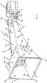
- the Figure 1 shows an embodiment of a public address system 1 according to the present invention, wherein the Figure 1a an exploded view of the sound system 1 without mounting bracket, the Figure 1b a mounting bracket 10 for bringing into engagement with the sound system 1 according to FIG Figure 1a and the Figure 1c the sound system 1 from the Figure 1a with the mounting bracket 10 Figure 1b demonstrate.
- the sonication device 1 has a horn 4 in the form of a funnel-shaped hollow body with a sound inlet opening 5 and a sound outlet opening 6.
- a first, flat side surface 4a extends from the sound inlet opening 5 to the sound outlet opening 6.
- a second side surface 4b Opposite to the first, flat side surface 4a, a second side surface 4b, which is concave outward from the sound inlet opening 5 to the sound outlet opening 6, connects the sound inlet opening 5 and the sound outlet opening 6th
- the cross section of the hollow body is continuously rectangular and widens from the sound inlet opening 5 to the sound outlet opening 6, the sound inlet opening 5 having a circular opening cross section, which, however, merges directly into a rectangular cross section.
- the sound inlet opening 5 is a central, circular opening in an essentially flat flange plate 4e, which is placed flush on the end of the horn, which has a rectangular cross section, or is connected in one piece to it.
- the sound outlet opening 6 has a rectangular opening cross section.
- the cross-sectional areas of the sound inlet to the sound outlet are roughly 1: 180, with the distance between the sound inlet and the sound outlet being about 20% to 60% larger than the width of the sound outlet, which in turn is about twice the height of this sound outlet.
- a sound generator 2 is arranged at or near the sound inlet opening 5.
- the sound generator 2 has an opening behind which a sound-generating membrane is arranged.
- the opening of the sounder 2 is aligned with the sound inlet opening 5, the diameter of the opening of the sounder 2 corresponding to the diameter of the sound inlet opening 5.
- the surface of the membrane projected along the main emission direction into a plane perpendicular to this plane lies in the sound inlet opening 5 or covers it.
- the axis of symmetry of such a diaphragm which is typically circular or rotationally symmetrical, and the main emission direction then coincide.
- the sound generator 2 converts an electrical signal into an acoustic signal.
- the acoustic signal is passed through the sound inlet opening 5 into the horn 4. Since the sound generator 2 is arranged directly on the sound inlet opening 5, there are no noteworthy reflections at the sound inlet opening 5 which could worsen the acoustic signal.
- the acoustic signal conducted into the horn 4 propagates in the funnel-shaped hollow body.
- the sound generator 2 is also arranged directly next to the flat side surface 4a or an imaginary extension of the same in such a way that its main emission direction 3 is parallel and slightly The distance to the flat side surface 4a from the sound inlet opening 5 to the sound outlet opening 6 runs.
- the housing 9 is sealed off from the horn 4 with a seal 9a, so that the housing 9 is sealed off in a waterproof and dustproof manner.
- the sound outlet opening 6 has a stiffening bead, i.e. a peripheral edge reinforcement 6c.
- the stiffening bead stiffens the sound outlet opening 6 and prevents it from being set into natural oscillation during operation.
- the inner corners 6a of the sound outlet opening 6 have a rounding 6b with a radius of a few millimeters.
- Grid 7 arranged.
- the grid 7 sits in a grid receptacle, for example in the form of shallow grooves or projections that are in the Figure 1 are not shown, and is screwed with four countersunk screws to the flat side surface 4a and the concave side surface 4b of the horn.
- the center-to-center distance between adjacent openings of the grid 7 is constant.
- the grating 7 is arranged inclined at an angle of 65 ° to the flat side surface 4 a and in the direction of the sound inlet opening 5.
- the edge of the arranged on the flat side surface 4a The grille 7 is arranged further away from the sound inlet opening 5 than the edge of the grille 7 arranged on the concave side surface 4b.
- the horn 4 has two holding devices 11 on each of its two opposite sides 4c and 4d.
- the holding devices 11 are wedge-shaped material reinforcements into which a screw or a threaded bolt with a screw nut can be screwed.
- Two holding devices 11 each are arranged at the end of the horn 4 with the sound outlet opening 6 and the end of the horn 4 with the sound inlet opening 5.
- the assembly bracket 10 provided for engaging with the holding devices 11 is shown in FIG Figure 1b shown.
- the mounting bracket 10 has two U-shaped brackets 10a which are aligned parallel to one another and are connected to one another via a web 10b.
- Each bracket 10a has two legs 10c with an elongated hole 10d and an insertion aid 10e for at least partially gripping around the horn 4.
- the screw screwed into the holding device 11 is guided into the elongated hole 10d via the insertion aid 10e.
- the position of the horn 4 relative to the mounting bracket 10 can be adjusted by moving the screw in the elongated hole 10d.
- the screws are then tightened and firmly connect the legs 10c to the holding devices 11.
- FIG. 1c is the public address system 1 according to FIG Figure 1a with an attached mounting bracket 10 according to the Figure 1b shown.
- the web 10b of the mounting bracket 10 clearly extends in the direction from the sound inlet opening 5 to the sound outlet opening 6.
- the web 10b is at a distance from the flat side surface 4a of the horn.
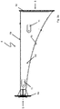
- the Figure 2 shows a horn 4 of a further embodiment of a sound system 1 according to the present invention. That in the Figure 2 Horn 4 shown is for the in Figure 1 Sound system 1 shown provided, wherein in the Figure 2a a side view, in FIG. 2b a plan view of the rear side of the sound inlet opening 5 and in FIG Figure 2c a plan view of the first, flat side surface 4a of the horn 4 are shown.
- the first, flat side surface 4a of the horn 4 extends from the sound inlet opening 5 to the sound outlet opening 6 and thus connects the sound inlet opening 5 with the sound outlet opening 6.
- a second, concave side surface 4b of the horn 4 is arranged opposite the first, flat side surface 4a.
- the second, concave side surface 4b also connects the sound inlet opening 5 to the sound outlet opening 6 and, together with the two further side surfaces 4c, 4d, forms a funnel-shaped hollow body through which the acoustic signal is passed when the sound system is in operation.
- the Indian Figure 2 Sound generator 2 not shown, is arranged close to or at the sound inlet opening 5 during operation of the sound reinforcement device.
- the sounder 2 is attached to the flange 4e of the horn in such a way that the sounder is arranged directly next to the flat side surface 4a or an imaginary extension of the flat side surface 4a and its main emission direction is parallel to the first, flat side surface 4a runs from the sound inlet opening 5 to the sound outlet opening 6.
- the flange 4e is also used to attach a, in the Figure 2 also not shown, housing 9, which protects the sound generator 2 from environmental influences when the sound system is in operation.
- the holding devices 11 are arranged in such a way that, when the sound system is in operation, the web 10b of a mounting bracket 10 is arranged at a distance from the first, flat side surface 4a. The distance is preferably chosen so that the web 2 in one in the Figure 2a The side view shown is flush with the upper edge of the flange 4e.
- the horn 4 has an edge reinforcement 6c, which prevents the horn 4 from being set into natural oscillations by the sound guided through the horn 4 during operation of the sound system.
- the Figure 2b shows the horn 4 in a plan view of the rear side of the sound inlet opening 5.
- the sound inlet opening 5 is a circular opening in the flange 4e.
- the diameter of the sound inlet opening 5 is preferably selected such that it corresponds to the diameter of a membrane of a sounder 2 which is arranged on or near the sound inlet opening 5 during operation of the sound system.
- the sound inlet opening 5 is arranged in the flange 4e in such a way that the edge of the sound inlet opening 5 lies directly next to the first, flat side surface 4a.
- FIG. 2c shows a plan view of the first, flat side surface 4a, to recognize the holding devices 11 attached to each of the two side surfaces 4c, 4d for bringing it into engagement with a mounting bracket 10.
- the holding devices 11 are wedge-shaped material reinforcements of the side walls 4c, 4d.
Landscapes
- Physics & Mathematics (AREA)
- Engineering & Computer Science (AREA)
- Acoustics & Sound (AREA)
- Multimedia (AREA)
- Apparatuses For Generation Of Mechanical Vibrations (AREA)
- Obtaining Desirable Characteristics In Audible-Bandwidth Transducers (AREA)
- Transducers For Ultrasonic Waves (AREA)
- Circuit For Audible Band Transducer (AREA)
Priority Applications (1)
| Application Number | Priority Date | Filing Date | Title |
|---|---|---|---|
| PL17160914T PL3226237T3 (pl) | 2016-04-01 | 2017-03-14 | Urządzenie nagłaśniające |
Applications Claiming Priority (1)
| Application Number | Priority Date | Filing Date | Title |
|---|---|---|---|
| DE102016106045.3A DE102016106045A1 (de) | 2016-04-01 | 2016-04-01 | Beschallungseinrichtung |
Publications (3)
| Publication Number | Publication Date |
|---|---|
| EP3226237A2 EP3226237A2 (de) | 2017-10-04 |
| EP3226237A3 EP3226237A3 (de) | 2017-12-27 |
| EP3226237B1 true EP3226237B1 (de) | 2021-01-13 |
Family
ID=58387630
Family Applications (1)
| Application Number | Title | Priority Date | Filing Date |
|---|---|---|---|
| EP17160914.2A Active EP3226237B1 (de) | 2016-04-01 | 2017-03-14 | Beschallungseinrichtung |
Country Status (4)
| Country | Link |
|---|---|
| EP (1) | EP3226237B1 (pl) |
| DE (1) | DE102016106045A1 (pl) |
| ES (1) | ES2846865T3 (pl) |
| PL (1) | PL3226237T3 (pl) |
Family Cites Families (13)
| Publication number | Priority date | Publication date | Assignee | Title |
|---|---|---|---|---|
| US718073A (en) * | 1902-09-24 | 1903-01-13 | Walter Barnes | Support for horns for talking-machines. |
| US898520A (en) * | 1907-08-27 | 1908-09-15 | Samuel D Solomon | Megaphone-holder for phonograph-cabinets. |
| US1532811A (en) * | 1924-08-29 | 1925-04-07 | Graham Edward Alfred | Cabinet for use with sound-reproducing devices |
| US4171678A (en) * | 1977-07-22 | 1979-10-23 | Midland-Ross Corporation | Air horn |
| JPS5834863Y2 (ja) * | 1979-07-11 | 1983-08-05 | 松下電器産業株式会社 | ホ−ンスピ−カ |
| JPS5890794U (ja) * | 1981-12-15 | 1983-06-20 | 日本電音株式会社 | ストレ−トホ−ンスピ−カ |
| JPH02211798A (ja) * | 1989-02-10 | 1990-08-23 | J F B:Kk | 低音用ホーンスピーカ |
| JPH07322387A (ja) * | 1994-05-24 | 1995-12-08 | Sony Corp | 音響装置 |
| US6516741B1 (en) * | 2000-09-12 | 2003-02-11 | Hadley Products | Leak proof apparatus for mounting components to panels |
| NL1019961C2 (nl) * | 2002-02-14 | 2003-08-15 | Duran Audio B V | Akoestische weergever. |
| DE10338539A1 (de) * | 2003-08-19 | 2005-03-31 | Ebe Elektro-Bau-Elemente Gmbh | Signalgeber für Straßenbahnen und dgl. |
| NL2011074C2 (en) * | 2013-07-01 | 2015-01-05 | Duran Audio B V | Sound speaker grill arrangement and sound speaker comprising such grill arrangement. |
| CN203596900U (zh) * | 2013-11-26 | 2014-05-14 | 天津中环真美声学技术有限公司 | 扬声器用增益导向号筒 |
-
2016
- 2016-04-01 DE DE102016106045.3A patent/DE102016106045A1/de not_active Withdrawn
-
2017
- 2017-03-14 PL PL17160914T patent/PL3226237T3/pl unknown
- 2017-03-14 EP EP17160914.2A patent/EP3226237B1/de active Active
- 2017-03-14 ES ES17160914T patent/ES2846865T3/es active Active
Non-Patent Citations (1)
| Title |
|---|
| None * |
Also Published As
| Publication number | Publication date |
|---|---|
| EP3226237A2 (de) | 2017-10-04 |
| PL3226237T3 (pl) | 2021-08-16 |
| DE102016106045A1 (de) | 2017-10-05 |
| ES2846865T3 (es) | 2021-07-29 |
| EP3226237A3 (de) | 2017-12-27 |
Similar Documents
| Publication | Publication Date | Title |
|---|---|---|
| DE60115148T2 (de) | Lautsprecher für Decken mit direkter Verlegung | |
| EP2187659B1 (de) | Lautsprechereinheit | |
| EP2734860B1 (de) | Montageverbund eines kraftfahrzeugs | |
| DE102012107645B4 (de) | Akustischer wandler | |
| DE2504377A1 (de) | Pyramidenfoermiger beugungslautsprecher mit geringer verzerrung | |
| EP3226237B1 (de) | Beschallungseinrichtung | |
| EP1258848A2 (de) | Optischer Rauchmelder | |
| EP0280162A2 (de) | Lautsprecherbox mit einem luftdicht abgeschlossenen Gehäuse | |
| DE19650522C2 (de) | Kegelförmiger Lautsprechervorsatz | |
| DE3420439A1 (de) | Gehaeuse fuer ueberwachungsanlagen | |
| WO2003049493A1 (de) | Displayfenster zur schallabstrahlung in kommunikations- und multimediageräten | |
| EP1630311B1 (de) | Schallabsorbierende Vorrichtung, insbesondere zur Montage an einer Decke oder Wand | |
| DE20112669U1 (de) | Schallabsorbierendes Paneel | |
| EP1142445A2 (de) | Tiefton-membranlautsprecher | |
| DE102016000877A1 (de) | Lautsprecheranordnung | |
| EP2768238B1 (de) | Deckenlautsprecher mit einer Abdeckung | |
| DE2140926B2 (de) | Lautsprecheranordnung zur Erzeu gung einer in Ebenen senkrecht zu einer Achse gleichförmigen Rundum charakteristik | |
| DE2523854A1 (de) | Akustischer alarmgeber mit schalldaempfungseinrichtung | |
| DE102005030712B4 (de) | Lautsprecherbox | |
| DE202015005705U1 (de) | Lautsprecheranordnung | |
| DE202023000588U1 (de) | Doppelreflektor-Element in schallharter Ausführung, den Raumkanteneffekt löschend und die Schallenergie harmonisierend, insbesondere mittlere und höhere Frequenzen unterstützend, für kleine bis mittelgroße Räume | |
| DE102021101517A1 (de) | Lautsprecheranordnung und Raum | |
| DE102018122493A1 (de) | Innenraumüberwachungsvorrichtung für ein Fahrzeug, Diebstahlwarnvorrichtung und Dachbedienvorrichtung | |
| EP4086397A1 (de) | Verfahren zur schalldämmenden montage eines sanitärartikels und entsprechender sanitärartikel | |
| AT10910U1 (de) | Akustikpaneel |
Legal Events
| Date | Code | Title | Description |
|---|---|---|---|
| PUAI | Public reference made under article 153(3) epc to a published international application that has entered the european phase |
Free format text: ORIGINAL CODE: 0009012 |
|
| STAA | Information on the status of an ep patent application or granted ep patent |
Free format text: STATUS: THE APPLICATION HAS BEEN PUBLISHED |
|
| AK | Designated contracting states |
Kind code of ref document: A2 Designated state(s): AL AT BE BG CH CY CZ DE DK EE ES FI FR GB GR HR HU IE IS IT LI LT LU LV MC MK MT NL NO PL PT RO RS SE SI SK SM TR |
|
| AX | Request for extension of the european patent |
Extension state: BA ME |
|
| PUAL | Search report despatched |
Free format text: ORIGINAL CODE: 0009013 |
|
| AK | Designated contracting states |
Kind code of ref document: A3 Designated state(s): AL AT BE BG CH CY CZ DE DK EE ES FI FR GB GR HR HU IE IS IT LI LT LU LV MC MK MT NL NO PL PT RO RS SE SI SK SM TR |
|
| AX | Request for extension of the european patent |
Extension state: BA ME |
|
| RIC1 | Information provided on ipc code assigned before grant |
Ipc: G10K 13/00 20060101ALI20171117BHEP Ipc: G10K 11/02 20060101AFI20171117BHEP |
|
| STAA | Information on the status of an ep patent application or granted ep patent |
Free format text: STATUS: REQUEST FOR EXAMINATION WAS MADE |
|
| 17P | Request for examination filed |
Effective date: 20180416 |
|
| RBV | Designated contracting states (corrected) |
Designated state(s): AL AT BE BG CH CY CZ DE DK EE ES FI FR GB GR HR HU IE IS IT LI LT LU LV MC MK MT NL NO PL PT RO RS SE SI SK SM TR |
|
| STAA | Information on the status of an ep patent application or granted ep patent |
Free format text: STATUS: EXAMINATION IS IN PROGRESS |
|
| 17Q | First examination report despatched |
Effective date: 20190524 |
|
| GRAP | Despatch of communication of intention to grant a patent |
Free format text: ORIGINAL CODE: EPIDOSNIGR1 |
|
| STAA | Information on the status of an ep patent application or granted ep patent |
Free format text: STATUS: GRANT OF PATENT IS INTENDED |
|
| INTG | Intention to grant announced |
Effective date: 20201106 |
|
| GRAS | Grant fee paid |
Free format text: ORIGINAL CODE: EPIDOSNIGR3 |
|
| GRAA | (expected) grant |
Free format text: ORIGINAL CODE: 0009210 |
|
| STAA | Information on the status of an ep patent application or granted ep patent |
Free format text: STATUS: THE PATENT HAS BEEN GRANTED |
|
| AK | Designated contracting states |
Kind code of ref document: B1 Designated state(s): AL AT BE BG CH CY CZ DE DK EE ES FI FR GB GR HR HU IE IS IT LI LT LU LV MC MK MT NL NO PL PT RO RS SE SI SK SM TR |
|
| REG | Reference to a national code |
Ref country code: GB Ref legal event code: FG4D Free format text: NOT ENGLISH |
|
| REG | Reference to a national code |
Ref country code: CH Ref legal event code: EP |
|
| REG | Reference to a national code |
Ref country code: DE Ref legal event code: R096 Ref document number: 502017009026 Country of ref document: DE |
|
| REG | Reference to a national code |
Ref country code: IE Ref legal event code: FG4D Free format text: LANGUAGE OF EP DOCUMENT: GERMAN |
|
| REG | Reference to a national code |
Ref country code: AT Ref legal event code: REF Ref document number: 1355137 Country of ref document: AT Kind code of ref document: T Effective date: 20210215 |
|
| REG | Reference to a national code |
Ref country code: CH Ref legal event code: NV Representative=s name: ISLER AND PEDRAZZINI AG, CH |
|
| REG | Reference to a national code |
Ref country code: NL Ref legal event code: FP |
|
| REG | Reference to a national code |
Ref country code: LT Ref legal event code: MG9D |
|
| REG | Reference to a national code |
Ref country code: ES Ref legal event code: FG2A Ref document number: 2846865 Country of ref document: ES Kind code of ref document: T3 Effective date: 20210729 |
|
| PG25 | Lapsed in a contracting state [announced via postgrant information from national office to epo] |
Ref country code: HR Free format text: LAPSE BECAUSE OF FAILURE TO SUBMIT A TRANSLATION OF THE DESCRIPTION OR TO PAY THE FEE WITHIN THE PRESCRIBED TIME-LIMIT Effective date: 20210113 Ref country code: GR Free format text: LAPSE BECAUSE OF FAILURE TO SUBMIT A TRANSLATION OF THE DESCRIPTION OR TO PAY THE FEE WITHIN THE PRESCRIBED TIME-LIMIT Effective date: 20210414 Ref country code: FI Free format text: LAPSE BECAUSE OF FAILURE TO SUBMIT A TRANSLATION OF THE DESCRIPTION OR TO PAY THE FEE WITHIN THE PRESCRIBED TIME-LIMIT Effective date: 20210113 Ref country code: NO Free format text: LAPSE BECAUSE OF FAILURE TO SUBMIT A TRANSLATION OF THE DESCRIPTION OR TO PAY THE FEE WITHIN THE PRESCRIBED TIME-LIMIT Effective date: 20210413 Ref country code: PT Free format text: LAPSE BECAUSE OF FAILURE TO SUBMIT A TRANSLATION OF THE DESCRIPTION OR TO PAY THE FEE WITHIN THE PRESCRIBED TIME-LIMIT Effective date: 20210513 Ref country code: BG Free format text: LAPSE BECAUSE OF FAILURE TO SUBMIT A TRANSLATION OF THE DESCRIPTION OR TO PAY THE FEE WITHIN THE PRESCRIBED TIME-LIMIT Effective date: 20210413 Ref country code: LT Free format text: LAPSE BECAUSE OF FAILURE TO SUBMIT A TRANSLATION OF THE DESCRIPTION OR TO PAY THE FEE WITHIN THE PRESCRIBED TIME-LIMIT Effective date: 20210113 |
|
| PG25 | Lapsed in a contracting state [announced via postgrant information from national office to epo] |
Ref country code: SE Free format text: LAPSE BECAUSE OF FAILURE TO SUBMIT A TRANSLATION OF THE DESCRIPTION OR TO PAY THE FEE WITHIN THE PRESCRIBED TIME-LIMIT Effective date: 20210113 Ref country code: RS Free format text: LAPSE BECAUSE OF FAILURE TO SUBMIT A TRANSLATION OF THE DESCRIPTION OR TO PAY THE FEE WITHIN THE PRESCRIBED TIME-LIMIT Effective date: 20210113 Ref country code: LV Free format text: LAPSE BECAUSE OF FAILURE TO SUBMIT A TRANSLATION OF THE DESCRIPTION OR TO PAY THE FEE WITHIN THE PRESCRIBED TIME-LIMIT Effective date: 20210113 |
|
| PG25 | Lapsed in a contracting state [announced via postgrant information from national office to epo] |
Ref country code: IS Free format text: LAPSE BECAUSE OF FAILURE TO SUBMIT A TRANSLATION OF THE DESCRIPTION OR TO PAY THE FEE WITHIN THE PRESCRIBED TIME-LIMIT Effective date: 20210513 |
|
| REG | Reference to a national code |
Ref country code: DE Ref legal event code: R097 Ref document number: 502017009026 Country of ref document: DE |
|
| PG25 | Lapsed in a contracting state [announced via postgrant information from national office to epo] |
Ref country code: MC Free format text: LAPSE BECAUSE OF FAILURE TO SUBMIT A TRANSLATION OF THE DESCRIPTION OR TO PAY THE FEE WITHIN THE PRESCRIBED TIME-LIMIT Effective date: 20210113 Ref country code: CZ Free format text: LAPSE BECAUSE OF FAILURE TO SUBMIT A TRANSLATION OF THE DESCRIPTION OR TO PAY THE FEE WITHIN THE PRESCRIBED TIME-LIMIT Effective date: 20210113 Ref country code: EE Free format text: LAPSE BECAUSE OF FAILURE TO SUBMIT A TRANSLATION OF THE DESCRIPTION OR TO PAY THE FEE WITHIN THE PRESCRIBED TIME-LIMIT Effective date: 20210113 Ref country code: SM Free format text: LAPSE BECAUSE OF FAILURE TO SUBMIT A TRANSLATION OF THE DESCRIPTION OR TO PAY THE FEE WITHIN THE PRESCRIBED TIME-LIMIT Effective date: 20210113 |
|
| PLBE | No opposition filed within time limit |
Free format text: ORIGINAL CODE: 0009261 |
|
| STAA | Information on the status of an ep patent application or granted ep patent |
Free format text: STATUS: NO OPPOSITION FILED WITHIN TIME LIMIT |
|
| PG25 | Lapsed in a contracting state [announced via postgrant information from national office to epo] |
Ref country code: DK Free format text: LAPSE BECAUSE OF FAILURE TO SUBMIT A TRANSLATION OF THE DESCRIPTION OR TO PAY THE FEE WITHIN THE PRESCRIBED TIME-LIMIT Effective date: 20210113 Ref country code: SK Free format text: LAPSE BECAUSE OF FAILURE TO SUBMIT A TRANSLATION OF THE DESCRIPTION OR TO PAY THE FEE WITHIN THE PRESCRIBED TIME-LIMIT Effective date: 20210113 Ref country code: RO Free format text: LAPSE BECAUSE OF FAILURE TO SUBMIT A TRANSLATION OF THE DESCRIPTION OR TO PAY THE FEE WITHIN THE PRESCRIBED TIME-LIMIT Effective date: 20210113 |
|
| 26N | No opposition filed |
Effective date: 20211014 |
|
| PG25 | Lapsed in a contracting state [announced via postgrant information from national office to epo] |
Ref country code: LU Free format text: LAPSE BECAUSE OF NON-PAYMENT OF DUE FEES Effective date: 20210314 Ref country code: AL Free format text: LAPSE BECAUSE OF FAILURE TO SUBMIT A TRANSLATION OF THE DESCRIPTION OR TO PAY THE FEE WITHIN THE PRESCRIBED TIME-LIMIT Effective date: 20210113 Ref country code: IE Free format text: LAPSE BECAUSE OF NON-PAYMENT OF DUE FEES Effective date: 20210314 |
|
| PG25 | Lapsed in a contracting state [announced via postgrant information from national office to epo] |
Ref country code: SI Free format text: LAPSE BECAUSE OF FAILURE TO SUBMIT A TRANSLATION OF THE DESCRIPTION OR TO PAY THE FEE WITHIN THE PRESCRIBED TIME-LIMIT Effective date: 20210113 |
|
| PG25 | Lapsed in a contracting state [announced via postgrant information from national office to epo] |
Ref country code: IS Free format text: LAPSE BECAUSE OF FAILURE TO SUBMIT A TRANSLATION OF THE DESCRIPTION OR TO PAY THE FEE WITHIN THE PRESCRIBED TIME-LIMIT Effective date: 20210513 |
|
| PG25 | Lapsed in a contracting state [announced via postgrant information from national office to epo] |
Ref country code: HU Free format text: LAPSE BECAUSE OF FAILURE TO SUBMIT A TRANSLATION OF THE DESCRIPTION OR TO PAY THE FEE WITHIN THE PRESCRIBED TIME-LIMIT; INVALID AB INITIO Effective date: 20170314 |
|
| PG25 | Lapsed in a contracting state [announced via postgrant information from national office to epo] |
Ref country code: CY Free format text: LAPSE BECAUSE OF FAILURE TO SUBMIT A TRANSLATION OF THE DESCRIPTION OR TO PAY THE FEE WITHIN THE PRESCRIBED TIME-LIMIT Effective date: 20210113 |
|
| PG25 | Lapsed in a contracting state [announced via postgrant information from national office to epo] |
Ref country code: MK Free format text: LAPSE BECAUSE OF FAILURE TO SUBMIT A TRANSLATION OF THE DESCRIPTION OR TO PAY THE FEE WITHIN THE PRESCRIBED TIME-LIMIT Effective date: 20210113 |
|
| PG25 | Lapsed in a contracting state [announced via postgrant information from national office to epo] |
Ref country code: MT Free format text: LAPSE BECAUSE OF FAILURE TO SUBMIT A TRANSLATION OF THE DESCRIPTION OR TO PAY THE FEE WITHIN THE PRESCRIBED TIME-LIMIT Effective date: 20210113 |
|
| PGFP | Annual fee paid to national office [announced via postgrant information from national office to epo] |
Ref country code: ES Payment date: 20250429 Year of fee payment: 9 |
|
| PGFP | Annual fee paid to national office [announced via postgrant information from national office to epo] |
Ref country code: CH Payment date: 20250401 Year of fee payment: 9 |
|
| PG25 | Lapsed in a contracting state [announced via postgrant information from national office to epo] |
Ref country code: TR Free format text: LAPSE BECAUSE OF FAILURE TO SUBMIT A TRANSLATION OF THE DESCRIPTION OR TO PAY THE FEE WITHIN THE PRESCRIBED TIME-LIMIT Effective date: 20210113 |
|
| REG | Reference to a national code |
Ref country code: CH Ref legal event code: U11 Free format text: ST27 STATUS EVENT CODE: U-0-0-U10-U11 (AS PROVIDED BY THE NATIONAL OFFICE) Effective date: 20260401 |
|
| PGFP | Annual fee paid to national office [announced via postgrant information from national office to epo] |
Ref country code: GB Payment date: 20260324 Year of fee payment: 10 |
|
| PGFP | Annual fee paid to national office [announced via postgrant information from national office to epo] |
Ref country code: DE Payment date: 20260310 Year of fee payment: 10 |
|
| PGFP | Annual fee paid to national office [announced via postgrant information from national office to epo] |
Ref country code: AT Payment date: 20260320 Year of fee payment: 10 |
|
| PGFP | Annual fee paid to national office [announced via postgrant information from national office to epo] |
Ref country code: IT Payment date: 20260324 Year of fee payment: 10 Ref country code: BE Payment date: 20260319 Year of fee payment: 10 |
|
| PGFP | Annual fee paid to national office [announced via postgrant information from national office to epo] |
Ref country code: NL Payment date: 20260319 Year of fee payment: 10 |
|
| PGFP | Annual fee paid to national office [announced via postgrant information from national office to epo] |
Ref country code: FR Payment date: 20260320 Year of fee payment: 10 |
|
| PGFP | Annual fee paid to national office [announced via postgrant information from national office to epo] |
Ref country code: PL Payment date: 20260219 Year of fee payment: 10 |