EP3225467B2 - Fahrzeugspiegel und verfahren zu dessen herstellung - Google Patents
Fahrzeugspiegel und verfahren zu dessen herstellung Download PDFInfo
- Publication number
- EP3225467B2 EP3225467B2 EP17163349.8A EP17163349A EP3225467B2 EP 3225467 B2 EP3225467 B2 EP 3225467B2 EP 17163349 A EP17163349 A EP 17163349A EP 3225467 B2 EP3225467 B2 EP 3225467B2
- Authority
- EP
- European Patent Office
- Prior art keywords
- mirror
- additional
- mirror housing
- housing
- glass
- Prior art date
- Legal status (The legal status is an assumption and is not a legal conclusion. Google has not performed a legal analysis and makes no representation as to the accuracy of the status listed.)
- Active
Links
Images

Classifications
-
- B—PERFORMING OPERATIONS; TRANSPORTING
- B60—VEHICLES IN GENERAL
- B60R—VEHICLES, VEHICLE FITTINGS, OR VEHICLE PARTS, NOT OTHERWISE PROVIDED FOR
- B60R1/00—Optical viewing arrangements; Real-time viewing arrangements for drivers or passengers using optical image capturing systems, e.g. cameras or video systems specially adapted for use in or on vehicles
- B60R1/02—Rear-view mirror arrangements
- B60R1/08—Rear-view mirror arrangements involving special optical features, e.g. avoiding blind spots, e.g. convex mirrors; Side-by-side associations of rear-view and other mirrors
- B60R1/081—Rear-view mirror arrangements involving special optical features, e.g. avoiding blind spots, e.g. convex mirrors; Side-by-side associations of rear-view and other mirrors avoiding blind spots, e.g. by using a side-by-side association of mirrors
- B60R1/082—Rear-view mirror arrangements involving special optical features, e.g. avoiding blind spots, e.g. convex mirrors; Side-by-side associations of rear-view and other mirrors avoiding blind spots, e.g. by using a side-by-side association of mirrors using a single wide field mirror or an association of rigidly connected mirrors
Definitions
- the invention relates to a vehicle mirror with a mirror housing to which a main mirror glass and at least one additional mirror glass are fixed, and a method for producing such a vehicle mirror.
- Vehicle mirrors in particular motor vehicle mirrors for land-based vehicles, but also for rail vehicles or boats, have a housing so that the vehicle mirror can be fixed to the respective vehicle.
- two types of mirrors are provided and prescribed, particularly for agricultural and forestry vehicles, commercial vehicles, namely a main mirror glass, through which the rear area should be able to be observed over a large area, and an additional mirror, which is intended for the close range and is intended to ensure that a Area is visible in close proximity to the mirror housing and below the mirror for the vehicle user. This is to prevent people next to the vehicle from being overlooked.
- a close-range mirror also makes it easier to maneuver the vehicle.
- Such vehicle mirrors can also be used for passenger cars.
- a housing is produced, for example by an injection molding process, into which both the main mirror glass and the additional mirror glass or near-range mirror glass are inserted and fixed therein. This can be done mechanically, for example via separate locking elements that engage in recesses or projections and positively fix the mirror in the housing. Alternatively or additionally, the mirror can be glued in or clamped in.
- the DE 10 2009 009 379 B3 relates to a mirror arrangement for vehicles with a plurality of glass units that are spatially separated from one another, the glass units consisting of a mirror glass and a frame surrounding this mirror glass, and the frames of a respective mirror unit having a permanent optical color marking.
- the U.S. 2004/184168 A1 relates to a foldable vehicle exterior mirror with a mirror housing which is arranged pivotably on a bracket which can be fixed on a vehicle door.
- a main mirror glass and a finder mirror glass arranged below the main mirror glass are fixed in the mirror housing.
- An auxiliary mirror is also arranged on the mirror housing, which enables a rearward view along the vehicle when the mirror housing is folded towards the vehicle.
- the DE 77 02 748 U1 relates to a vehicle rear view mirror with a mirror housing and a mirror glass arranged therein.
- the mirror housing has a rotatable mount for an arm of an auxiliary rear view mirror.
- the arm protrudes beyond the contour of the mirror housing.
- the additional rear view mirror is adjustable independently of the main mirror.
- the JP 2004-196224 A1 relates to an exterior mirror having a mirror base attached to a vehicle structure via a mounting plate.
- a mirror glass is arranged inside the mirror base.
- a second mirror housing is arranged below the base, in which a further mirror is arranged. The mirror in the mirror housing is larger than the mirror in the mirror base.
- the WO 96/04152 A1 relates to a rear-view mirror unit for vehicles with a mirror housing in which a flat mirror glass and a triangular prismatic mirror are arranged.
- the object of the present invention is to provide a vehicle mirror and a method for its production, with which tool costs can be saved, so that a cost-effective vehicle mirror can be provided with the same functionality.
- the vehicle mirror according to the invention with a mirror housing on which a main mirror glass and at least one additional mirror glass are fixed, with the additional mirror glass being fixed on a separate additional mirror housing, which in turn is fixed on a holding element of the mirror housing, provides that the holding element is designed as a frame, which is formed on the mirror housing and that at least one fixing element for fixing the additional mirror housing in or on the holding element is arranged on the additional mirror housing or the holding element, wherein a fixing element is arranged on the holding element and a corresponding fixing element is arranged on the additional mirror housing, which for one left-side or right-side arrangement is designed differently.
- the additional mirror housing Via the additional mirror housing, it is possible to provide an additional mirror glass that is mounted in a housing and is fully functional, and to attach this module made up of additional mirror housing and additional mirror glass to a holding element of the mirror housing provided for this purpose.
- the way in which it is fastened can be used to adjust the angle of the additional mirror glass relative to the main mirror glass, so that less effort has to be made in the mirror housing shapes for the entire vehicle mirror.
- the frame can be open, closed and in particular also shell-like in design, so that together with the mirror housing a surface is provided which closes the back of the mirror or mirrors in order to protect the mirror from environmental influences.
- the holding element can be molded onto it as part of a primary molding process. In the one-piece configuration of the retaining element on the mirror housing, the latter is rigidly fastened thereto, rotation or angular adjustability of the additional mirror glass relative to the main mirror glass cannot be effected by shifting the retaining element relative to the mirror housing.
- the orientation of the additional mirror glass to the main mirror glass which is carried out during the installation of the additional mirror, can take place by changing the orientation of the additional mirror housing in the holding element.
- the different orientation of the additional mirror glass to the main mirror glass can be achieved by two different additional mirror housings which are mounted at the same interface of the holding element, alternatively an additional mirror housing can be mounted in different ways at the interface of the holding element.
- the additional mirror housing is preferably shrunk into the holding element or alternatively can be attached to the holding element via form-fitting elements such as clips, spring shackles or projections that are formed or attached.
- the main mirror glass is preferably shrunk into the mirror housing, just as or alternatively the additional mirror glass can be shrunk into the additional mirror housing in order to fix the main mirror glass within the mirror housing and/or the additional mirror glass within the additional mirror housing without further fastening means.
- the additional mirror housing has at least one fixing element for attachment in or on the holding element, the at least one fixing element being attached to the additional mirror housing or formed thereon.
- the fixing element or the Fixing elements can be designed as a groove or grooves, a projection or projections, shoulders or just as markings or a combination thereof in order to either attach the additional mirror housing provided for the right or left side to it or to align and fix the additional mirror housing at an angle or to be able to carry out in the holding element according to the specifications or wishes of the users.
- a variant of the invention has two different additional mirror housings, which are designed differently for each side of the vehicle, so that they can be attached to the holding element via the fixing element or the fixing elements.
- Another variant provides that at least two fixing elements are arranged on the additional mirror housing relative to one another in such a way that the mirror housing can be attached to the holding element in different, predetermined angular positions, so that a standard setting for use on the right and/or left side of the vehicle is facilitated can be done.
- the fixing elements make it easier to align and fix the additional mirror housing within the mirror housing and allow vehicle mirrors to be produced for both the right and left side of the vehicle with just one additional mirror module, so that only one large tool mold for the vehicle mirror and a small tool mold for the two-sided usable additional mirror housing are necessary.
- fixing elements are preferably arranged in such a way that a right/left arrangement and an adaptation to different vehicle types, seat positions or other geometric conditions on the vehicle or in the vehicle can be carried out. This increases the flexibility and customizability of the vehicle mirrors.
- the mirror housing and/or the additional mirror housing are preferably designed as injection molded parts, which enable the respective housing to be manufactured quickly and cost-effectively.
- the method for manufacturing a vehicle mirror with a mirror housing, a main mirror glass and at least one additional mirror glass has the steps of manufacturing an additional mirror housing and setting the additional mirror glass to the additional mirror housing, manufacturing the mirror housing with a Recording for the main mirror glass and the holding element for the additional mirror housing and fixing the main mirror glass to the holder for the main mirror glass and fixing the additional mirror housing to the holding element, the holding element being molded onto the mirror housing.
- the production of the additional mirror module with additional mirror glass and additional mirror housing can take place independently of the production of the mirror housing and its assembly, so that it is possible to separate the production of the additional mirror module and its assembly. This increases manufacturing flexibility, since additional mirror modules can also be prefabricated and stored.
- the main mirror glass is preferably shrunk into the mirror housing and/or the additional mirror glass is shrunk into the additional mirror housing.
- the holding element is molded onto the mirror housing so that the assembly step of attaching the holding element to the mirror housing is omitted and the mirror housing can be produced in one piece together with the holding element, preferably using an injection molding process. Both the mirror housing and the additional mirror housing are preferably produced in an injection molding process. To fix the additional mirror housing in the holding element, the additional mirror housing is preferably shrunk into the holding element.
- the additional mirror housing is first produced using an injection molding process and the additional mirror glass is placed in the housing, for example placed on a shoulder, and you wait until the still warm plastic material removed from the injection mold has cooled and contracted, so that the additional mirror housing is shrunk .
- the mirror housing is injection molded, the main mirror glass is inserted and the complete additional mirror module with additional mirror housing and additional mirror glass is inserted into the holding element and waited until the material of the mirror housing has cooled down. Cooling shrinks the mirror housing and holds the auxiliary mirror housing in the desired orientation.
- a complete mirror, namely the additional mirror module is thus fixed, preferably shrunk, within the housing of another mirror, namely the vehicle mirror.
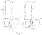
- both vehicle mirrors 1 are shown in a partially assembled state. Both vehicle mirrors 1 have a mirror housing 10 to which a main mirror glass 11 is attached. The main mirror glass 11 is inserted into a recess of the shell-like mirror housing 10 and held therein. The mirror housing 10 can completely surround the main mirror glass 11 and has an essentially closed surface on the back of the main mirror glass 11 . Fastening devices for fixing the vehicle mirror 1 to a vehicle are provided on the mirror housing 10 .
- Such a vehicle mirror 1 can be arranged on all vehicles, for example on trucks, buses, agricultural implements, rail vehicles or the like.
- Adjusting devices (not shown) for motorized adjustment of the vehicle mirror 1 can be arranged inside the mirror housing 10 on the fastening device (not shown), for example on the bracket or the like. Furthermore, additional components can be arranged within the mirror housing 10 and enclosed by the main mirror glass 11, for example heaters, cameras, sensors, transmitters or GPS receivers or the like.
- the main mirror glass 11 is preferably held in the mirror housing 10 in a form-fitting and clamping manner, in that the main mirror glass 11 is inserted into the receptacle of the mirror housing 10 provided for this purpose when the mirror housing 10 is in a heated state.
- the mirror housing 10 is then cooled down so that the main mirror glass 11 is shrunk into the mirror housing 10 .
- form-fitting elements can be provided in order to mechanically hold main mirror glass 11 within mirror housing 10, for example by means of projections or grooves over the entire circumference or over part of the circumference of main mirror glass 11 on mirror housing 10.
- a holding element 12 in the form of a frame is fastened to the mirror housing 10, either reversibly via fastening elements or formed on as part of the original molding process of the mirror housing 10, so that a one-piece configuration of the mirror housing 10 with a main mirror glass housing and a holding element 12 results .
- the holding element 12 is designed as a closed frame
- the holding element 12 is designed like a shell and, in addition to a peripheral edge, has a closed rear wall.
- a fixing element 13 in the form of a projection is formed on the inside of the holding element 12 .
- the fixing element 13 is designed as a circumferential projection; in principle, it is also possible that instead of a circumferential projection, a groove, several projections, shoulders, undercuts or the like are designed or arranged and fastened on the inside of the holding element 12, which are used for alignment an additional mirror module 2 are used.
- fixing elements 13, which are offset from one another, can be arranged or configured on the holding element 12, which are configured to correspond to fixing elements or positive-locking elements on the additional mirror module 2, so that an angular offset of the additional mirror module 2 relative to the main mirror 11 can be achieved simply by inserting it into the respective recess or alignment can take place on the respective fixing element.
- fixing elements 13, 22 for fixing the additional mirror housing 20 on the holding element 12 or on the additional mirror housing 20 can also be formed.
- different additional mirror housings 20 can be manufactured for the production of left and right vehicle mirrors 1, which are fixed in exactly one predetermined position in the holding element 12.
- the holding element 12 can also have an open cross section and thus have a resilient contact with an additional mirror glass 21 or an additional mirror housing 20 .
- figure 1 1 also shows an additional mirror housing 20 with an already installed additional mirror glass 21, which together form the additional mirror module 2, which is already prefabricated.
- the additional mirror glass 21 can be fastened in the additional mirror housing 20 in different ways; in addition to being glued in or clipped in or clamped, the additional mirror glass 21 can be shrunk into the additional mirror housing 20 . As in the case of the primary mirror glass 11 , this is effected by inserting the additional mirror glass 21 into the additional mirror housing 20 and then cooling the heated additional mirror housing 20 .
- the main mirror glass 11 can also be fixed in the mirror housing 10 in a different way, analogously to the additional mirror glass 21 , for example by gluing, clipping or clamping.
- At least one fixing element 22 in the form of a groove is formed inside the additional mirror housing 20 , which is formed in the retaining element 12 in a manner corresponding to the projection 13 .
- the additional mirror module 2 is inserted into the frame or the shell as a holding element 12, which is indicated by the arrow.
- the additional mirror housing 20 is then either held in the holding element 12 in a form-fitting, latching manner or is shrunk in when the still heated material of the mirror housing 10 with the holding element 12 formed on or arranged thereon is cooled.
- a plurality of fixing elements 13, 22 can be arranged both on the holding element 12 and on the additional mirror housing 20, which can also be designed only as markings, so that different positions of the additional mirror module 2 within the holding element 12 can be taken easily and repeatedly.
- the fixing elements 13, 22 are designed or arranged offset from one another in such a way that different angular positions of the additional mirror glass 21 relative to the main mirror glass 11 can be set. This makes it easy to orient the additional mirror glass 21 in the desired angular offset to the main mirror glass 11, so that the orientation of the additional mirror glass 21 can be easily adjusted to the respective vehicle type and the mounting side.
- the alignment of the mirror glasses 11, 21 to one another takes place via the attachment of the additional mirror module 2 to the holding element 12.
- the adjustment of the main mirror glass 11 relative to the driver takes place either during installation on the vehicle or by means of a motor, a separate adjustment of the additional mirror module 2 and thus of the Additional mirror 21 relative to the main mirror glass 11 does not take place.
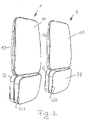
- FIG figure 2 shows the completely assembled vehicle mirror 1 according to FIG figure 1 with the additional mirror housing 20, which is attached to the respective holding element 12 of the mirror housing 10.
- figure 3 shows a rear view of the two vehicle mirror variants according to figure 1 in the assembled state.
- the illustration on the right shows the variant with the open frame element 12 as a holding element.
- the closed-walled rear side of the additional mirror housing 20 can be seen, as can the predominantly closed-walled rear side of the mirror housing 10.
- the illustration on the left shows the variant on the right according to FIG figure 1 with a shell-like design of the holding element 12.
- This design makes it possible to ensure a uniform material design of the mirror housing 10 in connection with the holding element 12 formed in one piece.
- the protection against mechanical damage is provided by a generally particularly durable material, so that the additional mirror housing 20 can be manufactured from a correspondingly less stable and less expensive material.
- Fastening devices 15 for mounting on the respective vehicle are formed on the rear side of the mirror housing 10, inside the mirror housing 12 further components can be arranged.
- the vehicle mirror 1 is attached to the vehicle by connecting, for example, an extension arm or carrier to the fastening device 15.
- an extension arm or carrier to the fastening device 15.
- variants with further additional mirror glasses on the vehicle mirror 10 can also be realized, for example with one above of the main mirror glass 11 arranged, downward second additional mirror glass and / or other additional mirror glasses.
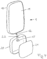
- a variant of a vehicle mirror 1 with a mirror housing 10 and a main mirror glass 11 fastened therein is shown.
- a retaining element 12 in the form of a pin with a detent formed or arranged on the outside, either fastened to the mirror housing 10 or formed thereon.
- a corresponding recess or detent is formed as a fixing element 22 on the additional mirror housing 20 to be mounted thereon, the detent on the holding element 12 being designed such that the additional mirror housing 20 can be fixed thereon in the desired position relative to the mirror housing 10 .
- the assembly is carried out by plugging the additional mirror housing 20 onto the retaining element 12, whereby at the same time as the angular alignment of the additional mirror housing 20 via the detent or the additional mirror housing fixing elements 22, it can also be fixed, for example by snapping in form-fitting elements, spreading apart elastically displaceable locking elements or the like.
- the additional mirror housing 20 can be fixed via a bracing element 25, which can be placed around the holding element 12 or fastened thereto, so that it can no longer be pulled out of the additional mirror housing 20 counter to the insertion direction of the holding element 12.
- the positive locking via the bracing element 25 can take place, for example, by inserting the bracing element 25 in a recess or on a projection of the holding element 12 .
Landscapes
- Engineering & Computer Science (AREA)
- Multimedia (AREA)
- Mechanical Engineering (AREA)
- Rear-View Mirror Devices That Are Mounted On The Exterior Of The Vehicle (AREA)
Description
- Die Erfindung betrifft einen Fahrzeugspiegel mit einem Spiegelgehäuse, an dem ein Hauptspiegelglas und zumindest ein Zusatzspiegelglas festgelegt sind sowie ein Verfahren zum Herstellen eines solchen Fahrzeugspiegels.
- Fahrzeugspiegel, insbesondere Kraftfahrzeugspiegel für landbetriebene Fahrzeuge, aber auch für schienengebundene Fahrzeuge oder Boote, weisen ein Gehäuse auf, so dass der Fahrzeugspiegel an dem jeweiligen Fahrzeug festlegbar ist. In dem Spiegelgehäuse sind insbesondere für land- und forstwirtschaftliche Fahrzeuge, Nutzfahrzeuge zwei Spiegelarten vorgesehen und vorgeschrieben, nämlich ein Hauptspiegelglas, über den der rückwärtige Bereich großflächig beobachtbar sein soll, sowie ein Zusatzspiegel, der für den Nahbereich vorgesehen ist und gewährleisten soll, dass auch ein Bereich in unmittelbarer Nähe zu dem Spiegelgehäuse und unterhalb des Spiegels für den Fahrzeugnutzer einsehbar ist. Dadurch soll verhindert werden, dass neben dem Fahrzeug befindliche Personen übersehen werden. Ein Nahbereichsspiegel erleichtert zudem das Rangieren des Fahrzeuges. Solche Fahrzeugspiegel sind auch für PKW einsetzbar.
- Zur Herstellung solcher Fahrzeugspiegel wird ein Gehäuse erzeugt, beispielsweise durch ein Spritzgussverfahren, in das sowohl das Hauptspiegelglas als auch das Zusatzspiegelglas bzw. Nahbereichsspiegelglas eingesetzt und darin fixiert werden. Dies kann mechanisch erfolgen, beispielsweise über separate Verriegelungselemente, die in Ausnehmungen oder Vorsprünge eingreifen und den Spiegel in dem Gehäuse formschlüssig festlegen. Alternativ oder ergänzend kann der Spiegel eingeklebt oder eingeklemmt werden.
- In der Regel ist es notwendig, dass für die rechte und linke Seite an dem Kraftfahrzeug unterschiedliche Fahrzeugspiegel vorgesehen sein müssen, damit der jeweils gewünschte Nahbereich eingesehen werden kann. Eine Verstellung der Spiegelgläser innerhalb des Spiegelgehäuses ist zu aufwendig, eine Anpassung an den jeweiligen Fahrzeugnutzer erfolgt durch eine Gesamtverstellung des Fahrzeugspiegels. Dies führt dazu, dass für die rechte und linke Fahrzeugseite unterschiedliche Spiegel und Spiegelgehäuse benötigt werden.
- Die
DE 10 2009 009 379 B3 betrifft eine Spiegelanordnung für Fahrzeuge mit einer Mehrzahl von räumlich voneinander getrennten Glaseinheiten, wobei die Glaseinheiten aus einem Spiegelglas und einem dieses Spiegelglas umgebenden Rahmen bestehen und die Rahmen einer jeweiligen Spiegeleinheit eine dauerhafte optische Farbmarkierung aufweisen. - Die
US 2004/184168 A1 betrifft einen klappbaren Fahrzeugaußenspiegel mit einem Spiegelgehäuse, das schwenkbar an einer Halterung angeordnet ist, die an einer Fahrzeugtür festlegbar ist. Ein Hauptspiegelglas und ein unterhalb des Hauptspiegelglases angeordnetes Sucherspiegelglas sind in dem Spiegelgehäuse befestigt. An dem Spiegelgehäuse ist zudem ein Hilfsspiegel angeordnet, der eine Sicht entlang dem Fahrzeug nach hinten ermöglicht, wenn das Spiegelgehäuse an das Fahrzeug herangeklappt ist. - Die
DE 77 02 748 U1 betrifft einen Fahrzeugrückspiegel mit einem Spiegelgehäuse und einem darin angeordneten Spiegelglas. Das Spiegelgehäuse weist eine drehbare Halterung für einen Arm eines Zusatzrückspiegels auf. Der Arm steht über die Kontur des Spiegelgehäuses hinaus vor. Der Zusatzrückspiegel ist von dem Hauptspiegel unabhängig verstellbar. - Die
JP 2004-196224 A1 - Die
WO 96/04152 A1 - Aufgabe der vorliegenden Erfindung ist es, einen Fahrzeugspiegel und ein Verfahren zu dessen Herstellung bereitzustellen, mit denen Werkzeugkosten eingespart werden können, so dass bei gleicher Funktionalität ein kostengünstiger Fahrzeugspiegel bereitgestellt werden kann.
- Erfindungsgemäß wird diese Aufgabe durch einen Fahrzeugspiegel mit den Merkmalen des Hauptanspruches und ein Verfahren mit den Merkmalen des nebengeordneten Anspruchs gelöst. Vorteilhafte Ausgestaltungen und Weiterbildungen der Erfindung sind in den Unteransprüchen, der Beschreibung sowie den Figuren näher erläutert.
- Der erfindungsgemäße Fahrzeugspiegel mit einem Spiegelgehäuse, an dem ein Hauptspiegelglas und zumindest ein Zusatzspiegelglas festgelegt sind, wobei das Zusatzspiegelglas an einem separaten Zusatzspiegelgehäuse festgelegt ist, das wiederum an einem Halteelement des Spiegelgehäuses befestigt ist, sieht vor, dass das Halteelement als ein Rahmen ausgebildet ist, der an dem Spiegelgehäuse angeformt ist und dass an dem Zusatzspiegelgehäuse oder dem Halteelement zumindest ein Fixierelement zur Festlegung des Zusatzspiegelgehäuses in oder an dem Halteelement angeordnet ist, wobei an dem Halteelement ein Fixierelement angeordnet ist und an dem Zusatzspiegelgehäuse ein korrespondierendes Fixierelement angeordnet ist, das für eine linksseitige oder rechtsseitige Anordnung verschieden ausgebildet ist. Über das Zusatzspiegelgehäuse ist es möglich, ein in einem Gehäuse montiertes Zusatzspiegelglas bereitzustellen, das vollständig funktionsfähig ist, und dieses Modul aus Zusatzspiegelgehäuse und Zusatzspiegelglas an einem dafür vorgesehenen Halteelement des Spiegelgehäuses zu befestigen. Über die Art und Weise der Befestigung kann eine Winkeleinstellung des Zusatzspiegelglases relativ zu dem Hauptspiegelglas erfolgen, so dass für den gesamten Fahrzeugspiegel ein verringerter Aufwand bei den Spiegelgehäuseformen betrieben werden muss. Statt zweier Formen für das Gesamtspiegelgehäuse wird nur eine Form für ein Spiegelgehäuse des Hauptspiegelglases sowie eine wesentlich kleinere und kostengünstigere Zusatzspiegelform, ggf. in zwei Varianten benötigt, um bei einer hohen Variabilität hinsichtlich der Fahrzeugspiegelgestaltung sowohl für die rechte Fahrzeugseite als auch für die linke Fahrzeugseite angepasste Fahrzeugspiegel herstellen zu können.
- Der Rahmen kann offen, geschlossen und insbesondere auch schalenartig ausgebildet sein, so dass zusammen mit dem Spiegelgehäuse eine die Rückseite des Spiegels bzw. der Spiegel geschlossene Fläche bereitgestellt wird, um die Spiegel vor Umwelteinflüssen zu schützen. Das Halteelement kann im Rahmen eines Urformverfahrens daran angeformt sein. Bei der einstückigen Ausgestaltung des Halteelementes an dem Spiegelgehäuse ist dieses starr daran befestigt, eine Verdrehung oder Winkeleinstellbarkeit des Zusatzspiegelglases zu dem Hauptspiegelglas kann durch eine Verlagerung des Halteelementes relativ zu dem Spiegelgehäuse nicht erfolgen. Die während der Zusatzspiegelmontage vorgenommene Orientierung des Zusatzspiegelglases zu dem Hauptspiegelglas kann durch Veränderung der Orientierung des Zusatzspiegelgehäuses in dem Halteelement erfolgen. Die unterschiedliche Orientierung des Zusatzspiegelglases zu dem Hauptspiegelglas kann durch zwei verschiedene Zusatzspiegelgehäuse erreicht werden, die an dieselbe Schnittstelle des Halteelementes montiert werden, alternativ kann ein Zusatzspiegelgehäuse auf unterschiedliche Art an der Schnittstelle des Halteelementes montiert werden.
- Das Zusatzspiegelgehäuse ist bevorzugt in dem Halteelement eingeschrumpft oder kann alternativ über Formschlusselemente wie Clipse, Federlaschen oder angeformte oder befestigte Vorsprünge an dem Halteelement befestigt sein.
- Das Hauptspiegelglas ist bevorzugt in dem Spiegelgehäuse eingeschrumpft, ebenso oder alternativ kann das Zusatzspiegelglas in dem Zusatzspiegelgehäuse eingeschrumpft sein, um ohne weitere Befestigungsmittel das Hauptspiegelglas innerhalb des Spiegelgehäuses und/oder das Zusatzspiegelglas innerhalb des Zusatzspiegelgehäuses festzulegen.
- Das Zusatzspiegelgehäuse weist zumindest ein Fixierelement zur Befestigung in oder an dem Halteelement auf, wobei das zumindest eine Fixierelement an dem Zusatzspiegelgehäuse befestigt oder daran angeformt ist. Das Fixierelement bzw. die Fixierelemente können als Nut oder Nuten, Vorsprung oder Vorsprünge, Absätze oder auch nur als Markierungen oder eine Kombination davon ausgebildet sein, um entweder das jeweils dafür vorgesehene Zusatzspiegelgehäuse für die rechte oder linke Seite daran zu befestigen oder um eine winklige Ausrichtung und Festlegung des Zusatzspiegelgehäuses an oder in dem Halteelement gemäß der Vorgaben oder Wünsche der Nutzer vornehmen zu können.
- Eine Variante der Erfindung weist zwei unterschiedliche Zusatzspiegelgehäuse auf, die für jede Fahrzeugseite unterschiedlich ausgebildet sind, so dass sie über das Fixierelement oder die Fixierelemente an dem Halteelement befestigt werden können. Eine andere Variante sieht vor, dass zumindest zwei Fixierelemente dergestalt zueinander an dem Zusatzspiegelgehäuse angeordnet sind, dass das Spiegelgehäuse in unterschiedlichen, vorbestimmten Winkelstellungen an dem Halteelement orientiert befestigt werden können, so dass eine Standardeinstellung für einen Einsatz rechts und/oder links an der Fahrzeugseite erleichtert vorgenommen werden kann. Die Fixierelemente erleichtern die Ausrichtung und Festlegung des Zusatzspiegelgehäuses innerhalb des Spiegelgehäuses und ermöglichen, dass mit nur einem Zusatzspiegelmodul Fahrzeugspiegel sowohl für die rechte als auch für die linke Fahrzeugseite herstellbar sind, so dass nur eine große Werkzeugform für den Fahrzeugspiegel und eine kleine Werkzeugform für das beidseitig verwendbare Zusatzspiegelgehäuse notwendig sind. Sofern mehrere Fixierelemente vorgesehen sind, sind diese bevorzugt so angeordnet, dass eine Rechts/Links-Anordnung sowie eine Anpassung an unterschiedliche Fahrzeugtypen, Sitzpositionen oder andere geometrische Gegebenheiten an dem Fahrzeug oder in dem Fahrzeug vorgenommen werden kann. Dies erhöht die Flexibilität und Individualisierbarkeit der Fahrzeugspiegel.
- Das Spiegelgehäuse und/oder das Zusatzspiegelgehäuse sind bevorzugt als Spritzgussteile ausgebildet, die eine schnelle und kostengünstige Fertigung der jeweiligen Gehäuse ermöglichen.
- Das Verfahren zum Herstellen eines Fahrzeugspiegels mit einem Spiegelgehäuse, einem Hauptspiegelglas und zumindest einem Zusatzspiegelglas weist die Schritte des Herstellens eines Zusatzspiegelgehäuses und Festlegen des Zusatzspiegelglases an dem Zusatzspiegelgehäuse, das Herstellen des Spiegelgehäuses mit einer Aufnahme für das Hauptspiegelglas und dem Halteelement für das Zusatzspiegelgehäuse sowie das Festlegen des Hauptspiegelglases an der Aufnahme für das Hauptspiegelglas und das Festlegen des Zusatzspiegelgehäuses an dem Halteelement auf, wobei das Haltelement an dem Spiegelgehäuse angeformt wird. Die Fertigung des Zusatzspiegelmoduls mit Zusatzspiegelglas und Zusatzspiegelgehäuse kann unabhängig von der Fertigung des Spiegelgehäuses und dessen Montage erfolgen, so dass eine Trennung von Fertigung des Zusatzspiegelmoduls und dessen Montage möglich ist. Dadurch erhöht sich die Fertigungsflexibilität, da Zusatzspiegelmodule auch vorgefertigt und gelagert werden können.
- Bevorzugt werden das Hauptspiegelglas in dem Spiegelgehäuse und/oder der Zusatzspiegelglas in dem Zusatzspiegelgehäuse eingeschrumpft. Das Halteelement wird an dem Spiegelgehäuse angeformt, so dass der Montageschritt der Befestigung des Halteelementes an dem Spiegelgehäuse wegfällt und das Spiegelgehäuse einstückig zusammen mit dem Halteelement bevorzugt im Rahmen eines Spritzgießverfahrens hergestellt werden kann. Sowohl das Spiegelgehäuse als auch das Zusatzspiegelgehäuse werden vorzugsweise in einem Spritzgießverfahren hergestellt. Zur Festlegung des Zusatzspiegelgehäuses in dem Halteelement wird das Zusatzspiegelgehäuse bevorzugt in dem Halteelement eingeschrumpft. Dazu wird zunächst das Zusatzspiegelgehäuse im Rahmen eines Spritzgießverfahrens hergestellt und das Zusatzspiegelglas in das Gehäuse eingelegt, beispielsweise auf einen Absatz abgelegt, und gewartet, bis sich das aus dem Spritzgießwerkzeug entnommene, noch warme Kunststoffmaterial abgekühlt und dabei zusammengezogen hat, so dass das Zusatzspiegelgehäuse eingeschrumpft wird. In einem anderen Werkzeug wird das Spiegelgehäuse spritzgegossen, das Hauptspiegelglas eingesetzt und das vollständige Zusatzspiegelmodul mit Zusatzspiegelgehäuse und eingesetztem Zusatzspiegelglas in das Halteelement eingesetzt und gewartet, bis sich das Material des Spiegelgehäuses abgekühlt hat. Durch das Abkühlen schrumpft das Spiegelgehäuse und hält das Zusatzspiegelgehäuse in der gewünschten Ausrichtung fest. Es wird somit ein vollständiger Spiegel, nämlich das Zusatzspiegelmodul innerhalb des Gehäuses eines anderen Spiegels, nämlich des Fahrzeugspiegels, festgelegt, bevorzugt eingeschrumpft.
- Nachfolgend wird ein Ausführungsbeispiel der Erfindung anhand der beigefügten Figuren näher erläutert. Es zeigen:
- Figur 1-
- eine perspektivische Darstellung zweier Fahrzeugspiegel vor der Endmontage;
- Figur 2-
- eine Darstellung zweier Fahrzeugspiegel in Schrägdraufsicht;
- Figur 3-
- zwei Fahrzeugspiel in montiertem Zustand in Rückansicht; sowie
- Figur 4-
- eine Variante der Spiegelgestaltung.
- In der
Figur 1 sind zwei Fahrzeugspiegel 1 in einem teilmontierten Zustand dargestellt. Beide Fahrzeugspiegel 1 weisen ein Spiegelgehäuse 10 auf, an dem ein Hauptspiegelglas 11 befestigt ist. Das Hauptspiegelglas 11 ist in einer Ausnehmung des schalenartigen Spiegelgehäuses 10 eingesetzt und darin gehalten. Das Spiegelgehäuse 10 kann das Hauptspiegelglas 11 vollumfänglich umgeben und weist auf der Rückseite des Hauptspiegelglases 11 eine im Wesentlichen geschlossene Oberfläche auf. An dem Spiegelgehäuse 10 sind Befestigungseinrichtungen zum Festlegen des Fahrzeugspiegels 1 an einem Fahrzeug vorgesehen. Ein solcher Fahrzeugspiegel 1 kann an allen Fahrzeugen angeordnet sein, beispielsweise an Lastkraftwagen, Bussen, landwirtschaftlichen Arbeitsgeräten, schienengebundenen Fahrzeugen oder dergleichen. Innerhalb des Spiegelgehäuses 10 können nicht dargestellte Verstelleinrichtungen zur motorischen Verstellung des Fahrzeugspiegels 1 an der nicht dargestellten Befestigungseinrichtung, beispielsweise an dem Ausleger oder dergleichen, angeordnet sein. Darüber hinaus können zusätzliche Komponenten innerhalb des Spiegelgehäuses 10 angeordnet und durch den Hauptspiegelglas 11 eingeschlossen sein, beispielsweise Heizeinrichtungen, Kameras, Sensoren, Sender oder GPS-Empfänger oder dergleichen. - Das Hauptspiegelglas 11 wird in dem Spiegelgehäuse 10 vorzugsweise formschlüssig und klemmend gehalten, indem das Hauptspiegelglas 11 in die dafür vorgesehene Aufnahme des Spiegelgehäuses 10 eingesetzt wird, wenn das Spiegelgehäuse 10 sich in einem erwärmten Zustand befindet. Anschließend wird das Spiegelgehäuse 10 abgekühlt wird, so dass das Hauptspiegelglas 11 in dem Spiegelgehäuse 10 eingeschrumpft wird. Alternativ oder ergänzend können Formschlusselemente vorgesehen sein, um einen mechanischen Halt des Hauptspiegelglases 11 innerhalb des Spiegelgehäuses 10 zu bewirken, beispielsweise durch Vorsprünge oder Rillen über den gesamten Umfang oder über einen Teilumfang des Hauptspiegelglases 11 an dem Spiegelgehäuse 10.
- Unterhalb des Hauptspiegelglases 11 ist an dem Spiegelgehäuse 10 ein Halteelement 12 in Gestalt eines Rahmens befestigt, entweder reversibel über Befestigungselemente oder aber im Rahmen des Urformverfahrens des Spiegelgehäuses 10 angeformt, so dass sich eine einstückige Ausgestaltung des Spiegelgehäuses 10 mit einem Hauptspiegelglasgehäuse und einem Halteelement 12 ergibt. In der linken Darstellung der
Figur 1 ist das Halteelement 12 als geschlossener Rahmen ausgebildet, in der rechten Darstellung derFigur 1 ist das Halteelement 12 schalenartig ausgebildet und weist neben einem umlaufenden Rand eine geschlossene Rückwand auf. - An der Innenseite des Halteelementes 12 ist ein Fixierelement 13 in Gestalt eines Vorsprunges ausgebildet. Im dargestellten Ausführungsbeispiel ist das Fixierelement 13 als umlaufender Vorsprung ausgebildet, grundsätzlich ist es auch möglich, dass statt eines umlaufenden Vorsprunges eine Nut, mehrere Vorsprünge, Absätze, Hinterschneidungen oder dergleichen ausgebildet oder an der Innenseite des Halteelementes 12 angeordnet und befestigt sind, die zur Ausrichtung eines Zusatzspiegelmoduls 2 dienen. Es können auch mehrere, zueinander versetzt angeordnete Fixierelemente 13 an dem Halteelement 12 angeordnet oder ausgebildet sind, die korrespondierend zu Fixierelementen oder Formschlusselementen an dem Zusatzspiegelmodul 2 ausgebildet sind, so dass ein Winkelversatz des Zusatzspiegelmoduls 2 zu dem Hauptspiegel 11 einfach durch Einsetzen in die jeweilige Ausnehmung oder Ausrichten an dem jeweiligen Fixierelement erfolgen kann. Es können auch mehrere Fixierelemente 13, 22 zur Festlegung des Zusatzspiegelgehäuses 20 an dem Halteelement 12 oder an dem Zusatzspiegelgehäuse 20 ausgebildet sein. Neben der Möglichkeit einer Ausrichtung und Festlegung des Zusatzspiegelgehäuses 20 in unterschiedlichen Ausrichtungen zu dem Halteelement 12 können unterschiedliche Zusatzspiegelgehäuse 20 für die Herstellung linker und rechter Fahrzeugspiegel 1 gefertigt werden, die in genau einer vorbestimmten Position in dem Halteelement 12 festgelegt werden.
- Neben einer geschlossenen Ausgestaltung des Halteelementes 12 als umlaufender Rahmen kann das Halteelement 12 auch einen offenen Querschnitt aufweisen und so eine federnde Anlage an einen Zusatzspiegelglas 21 oder ein Zusatzspiegelgehäuse 20 aufweisen.
-
Figur 1 zeigt weiterhin ein Zusatzspiegelgehäuse 20 mit einem bereits montierten Zusatzspiegelglas 21, die zusammen das Zusatzspiegelmodul 2 ausbilden, das bereits vorgefertigt ist. Das Zusatzspiegelglas 21 kann in dem Zusatzspiegelgehäuse 20 auf unterschiedliche Arten befestigt sein, neben einem Einkleben oder Einclipsen oder einer klemmenden Halterung kann das Zusatzspiegelglas 21 in das Zusatzspiegelgehäuse 20 eingeschrumpft sein. Dies wird wie bei dem Hauptspiegelglas 11 durch Einlegen des Zusatzspiegelglases 21 in das Zusatzspiegelgehäuse 20 und anschließendes Abkühlen des erwärmten Zusatzspiegelgehäuses 20 bewirkt. Das Hauptspiegelglas 11 kann analog zu dem Zusatzspiegelglas 21 auch auf andere Art und Weise in dem Spiegelgehäuse 10 befestigt werden, z.B. durch Einkleben, Einclipsen oder klemmende Halterung. - Innerhalb des Zusatzspiegelgehäuses 20 ist zumindest ein Fixierelement 22 in Gestalt einer Nut ausgebildet, die korrespondierend zu dem Vorsprung 13 in dem Halteelement 12 ausgebildet ist. Zur Montage des gesamten Fahrzeugspiegels 1 wird das Zusatzspiegelmodul 2 in den Rahmen oder die Schale als Halteelement 12 eingeführt, was durch den Pfeil angedeutet ist. Das Zusatzspiegelgehäuse 20 wird dann entweder formschlüssig einrastend in dem Halteelement 12 gehalten oder aber eingeschrumpft, wenn das noch erwärmte Material des Spiegelgehäuses 10 mit dem angeformten oder daran angeordneten Halteelement 12 abgekühlt wird.
- Sowohl an dem Halteelement 12 als auch an dem Zusatzspiegelgehäuse 20 können mehrere Fixierelemente 13, 22 angeordnet sein, die auch nur als Markierungen ausgebildet sein können, so dass unterschiedliche Positionen des Zusatzspiegelmoduls 2 innerhalb des Halteelementes 12 einfach und wiederholbar eingenommen werden können. In einer Variante sind die Fixierelemente 13, 22 so zueinander versetzt ausgebildet oder angeordnet, dass unterschiedliche Winkelstellungen des Zusatzspiegelglases 21 relativ zu dem Hauptspiegelglas 11 eingestellt werden können. Dadurch ist es leicht möglich, das Zusatzspiegelglas 21 in dem gewünschten Winkelversatz zu dem Hauptspiegelglas 11 zu orientieren, so dass eine leichte Anpassung der Ausrichtung des Zusatzspiegelglases 21 an den jeweiligen Fahrzeugtyp und die Montageseite vorgenommen werden kann. Die Ausrichtung der Spiegelgläser 11, 21 zueinander erfolgt über die Befestigung des Zusatzspiegelmoduls 2 an dem Halteelement 12. Die Einstellung des Hauptspiegelglases 11 relativ zu dem Fahrer erfolgt entweder bei der Montage an dem Fahrzeug oder aber motorisch, eine separate Verstellung des Zusatzspiegelmoduls 2 und damit des Zusatzspiegels 21 relativ zu dem Hauptspiegelglas 11 erfolgt nicht.
-
Figur 2 zeigt die fertig montierten Fahrzeugspiegel 1 gemäßFigur 1 mit dem Zusatzspiegelgehäuse 20, das an dem jeweiligen Halteelement 12 des Spiegelgehäuses 10 befestigt ist. -
Figur 3 zeigt eine Rückansicht der beiden Fahrzeugspiegelvarianten gemäßFigur 1 im endmontierten Zustand. Die rechte Darstellung zeigt die Variante mit dem offenen Rahmenelement 12 als Halteelement. Die geschlossenwandige Rückseite des Zusatzspiegelgehäuses 20 ist ebenso zu erkennen wie die überwiegend geschlossenwandige Rückseite des Spiegelgehäuses 10. Die linke Darstellung zeigt die rechte Variante gemäßFigur 1 mit einer schalenartigen Ausgestaltung des Halteelementes 12. Durch diese Ausgestaltung ist es möglich, eine gleichmäßige Materialgestaltung des Spiegelgehäuses 10 in Verbindung mit dem einstückig angeformten Halteelement 12 zu gewährleisten. Der Schutz gegen mechanische Beschädigungen wird durch ein in der Regel besonders haltbares Material bereitgestellt, so dass das Zusatzspiegelgehäuse 20 aus einem entsprechend weniger stabilen und preiswerten Material gefertigt werden kann. - An der Rückseite des Spiegelgehäuses 10 sind Befestigungseinrichtungen 15 für die Montage an dem jeweiligen Fahrzeug ausgebildet, innerhalb des Spiegelgehäuses 12 können weitere Komponenten angeordnet sein. Die Anbringung des Fahrzeugspiegels 1 an dem Fahrzeug gefolgt durch Verbinden beispielsweise eines Auslegers oder Trägers mit der Befestigungseinrichtung 15. Neben der dargestellten Ausführungsform mit einem Hauptspiegelglas 11 und einem Zusatzspiegelglas 21 können auch Varianten mit weiteren Zusatzspiegelgläsern an dem Fahrzeugspiegel 10 verwirklicht werden, beispielsweise mit einem oberhalb des Hauptspiegelglases 11 angeordneten, nach unten gerichteten zweiten Zusatzspiegelglas und/oder weiteren Zusatzspiegelgläsern.
- In der
Figur 4 ist eine Variante eines Fahrzeugspiegels 1 mit einem Spiegelgehäuse 10 und einem darin befestigten Hauptspiegelglas 11 gezeigt. An dem unteren Ende des Spiegelgehäuses 10 ist ein Halteelement 12 in Gestalt eines Zapfens mit einer an der Außenseite ausgebildeten oder angeordneten Rastung angeordnet, entweder an dem Spiegelgehäuse 10 befestigt oder daran ausgeformt. An dem daran zu montierenden Zusatzspiegelgehäuse 20 ist eine korrespondierende Ausnehmung oder Rastung als Fixierelement 22 ausgebildet, wobei die Rastung an dem Halteelement 12 so ausgebildet ist, dass das Zusatzspiegelgehäuse 20 in der gewünschten Stellung relativ zu dem Spiegelgehäuse 10 daran festgelegt werden kann. Die Montage erfolgt durch Aufstecken des Zusatzspiegelgehäuses 20 auf das Halteelement 12, wobei gleichzeitig mit der Winkelausrichtung des Zusatzspiegelgehäuses 20 über die Rastung beziehungsweise die Zusatzspiegelgehäusefixierelemente 22 auch eine Festlegung erfolgen kann, beispielsweise durch Einschnappen von Formschusselementen, Aufspreizen elastisch verlagerbarer Verriegelungselemente oder dergleichen. Alternativ kann über ein Verspannelement 25, das um das Halteelement 12 herumgelegt oder daran befestigt werden kann, eine Festlegung des Zusatzspiegelgehäuses 20 erfolgen, sodass dieses nicht mehr entgegen der Einführrichtung des Halteelementes 12 aus dem Zusatzspiegelgehäuse 20 ausgezogen werden kann. Die formschlüssige Verriegelung über das Verspannelement 25 kann beispielsweise durch Einlegen des Verspannelementes 25 in einer Ausnehmung oder an einen Vorsprung des Halteelementes 12 erfolgen.
Claims (9)
- Fahrzeugspiegel (1) mit einem Spiegelgehäuse (10), an dem ein Hauptspiegelglas (11) und zumindest ein Zusatzspiegelglas (21) festgelegt sind, wobei das Zusatzspiegelglas (21) in einem separaten Zusatzspiegelgehäuse (20) festgelegt ist, das an einem Halteelement (12) des Spiegelgehäuses (10) befestigt ist, dadurch gekennzeichnet, dass das Halteelement (12) als ein Rahmen ausgebildet ist, der an dem Spiegelgehäuse (10) angeformt ist und dass an dem Zusatzspiegelgehäuse (20) oder dem Halteelement (12) zumindest ein Fixierelement (13, 22) zur Festlegung des Zusatzspiegelgehäuses (20) in oder an dem Halteelement (12) angeordnet ist, wobei an dem Halteelement (12) ein Fixierelement (13) angeordnet ist und an dem Zusatzspiegelgehäuse (20) ein korrespondierendes Fixierelement (22) angeordnet ist, das für eine linksseitige oder rechtsseitige Anordnung verschieden ausgebildet ist.
- Fahrzeugspiegel (1) nach Anspruch 1, dadurch gekennzeichnet, dass das Zusatzspiegelgehäuse (20) in dem Halteelement (12) eingeschrumpft oder über Formschlusselemente daran befestigt ist.
- Fahrzeugspiegel (1) nach einem der voranstehenden Ansprüche, dadurch gekennzeichnet, dass das Hauptspiegelglas (11) in dem Spiegelgehäuse (10) und/oder der Zusatzspiegel (21) in dem Zusatzspiegelgehäuse (20) eingeschrumpft ist.
- Fahrzeugspiegel (1) nach Anspruch 1, dadurch gekennzeichnet, dass zumindest zwei Fixierelemente (13, 22) dergestalt versetzt zueinander an dem Zusatzspiegelgehäuse (20) oder dem Halteelement (12) angeordnet sind, dass das Zusatzspiegelgehäuse (20) in unterschiedlichen, vorbestimmten Winkelstellungen an dem Halteelement (12) orientierbar ist.
- Fahrzeugspiegel (1) nach einem der voranstehenden Ansprüche, dadurch gekennzeichnet, dass das Spiegelgehäuse (10) und/oder das Zusatzspiegelgehäuse (20) als Spritzgussteile ausgebildet sind.
- Verfahren zum Herstellen eines Fahrzeugspiegels (1) nach einem der voranstehenden Ansprüche mit einem Spiegelgehäuse (10), einem Hauptspiegelglas (11) und zumindest einem Zusatzspiegelglas (21), mit den Schritten:a. Herstellen eines Zusatzspiegelgehäuses (20) und Festlegen des Zusatzspiegelglases (21) an dem Zusatzspiegelgehäuse (20)b. Herstellen des Spiegelgehäuses (10) mit einer Aufnahme für den Hauptspiegelglas (11) und einem Halteelement (12) für das Zusatzspiegelgehäuse (20)c. Festlegen des Hauptspiegelglases (11) an der Aufnahme und des Zusatzspiegelgehäuses (20) an dem Halteelement (12), dadurch gekennzeichnet, dass das Haltelement (12) an dem Spiegelgehäuse (10) angeformt wird.
- Verfahren nach Anspruch 6, dadurch gekennzeichnet, dass das Hauptspiegelglas (11) in dem Spiegelgehäuse (10) und/oder das Zusatzspiegelglas (21) in dem Zusatzspiegelgehäuse (20) eingeschrumpft werden.
- Verfahren nach einem der Ansprüche 6 oder 7, dadurch gekennzeichnet, dass das Spiegelgehäuse (10) und/oder das Zusatzspiegelgehäuse (20) in einem Spritzgießverfahren hergestellt werden.
- Verfahren nach einem der Ansprüche 6 bis 8, dadurch gekennzeichnet, dass das Zusatzspiegelgehäuse (20) in das Halteelement (12) eingeschrumpft wird.
Priority Applications (1)
| Application Number | Priority Date | Filing Date | Title |
|---|---|---|---|
| PL17163349.8T PL3225467T5 (pl) | 2016-03-29 | 2017-03-28 | Lusterko pojazdu i sposób jego wytwarzania |
Applications Claiming Priority (1)
| Application Number | Priority Date | Filing Date | Title |
|---|---|---|---|
| DE102016105668.5A DE102016105668A1 (de) | 2016-03-29 | 2016-03-29 | Fahrzeugspiegel und Verfahren zu dessen Herstellung |
Publications (3)
| Publication Number | Publication Date |
|---|---|
| EP3225467A1 EP3225467A1 (de) | 2017-10-04 |
| EP3225467B1 EP3225467B1 (de) | 2018-11-21 |
| EP3225467B2 true EP3225467B2 (de) | 2022-04-27 |
Family
ID=58448466
Family Applications (1)
| Application Number | Title | Priority Date | Filing Date |
|---|---|---|---|
| EP17163349.8A Active EP3225467B2 (de) | 2016-03-29 | 2017-03-28 | Fahrzeugspiegel und verfahren zu dessen herstellung |
Country Status (3)
| Country | Link |
|---|---|
| EP (1) | EP3225467B2 (de) |
| DE (1) | DE102016105668A1 (de) |
| PL (1) | PL3225467T5 (de) |
Citations (5)
| Publication number | Priority date | Publication date | Assignee | Title |
|---|---|---|---|---|
| DE7702748U1 (de) † | Hagus-C. Luchtenberg Gmbh & Co Kg, 5650 Solingen | |||
| US20020141086A1 (en) † | 2000-07-28 | 2002-10-03 | Heinrich Lang | Rearview mirror assembly for a vehicle with monitor |
| DE202009015138U1 (de) † | 2009-10-29 | 2010-02-18 | Mekra Lang Gmbh & Co. Kg | Spiegelkopf mit überlappendem Sichtfeld |
| EP2735478A1 (de) † | 2012-11-22 | 2014-05-28 | MEKRA LANG GmbH & Co. KG | Spiegelkopf, insbesondere für einen Fahrzeugaußenspiegel |
| DE102014208687B3 (de) † | 2014-05-08 | 2015-10-08 | Mekra Lang Gmbh & Co. Kg | Aussenrückspiegel für ein Fahrzeug, insbesondere Nutzfahrzeug |
Family Cites Families (8)
| Publication number | Priority date | Publication date | Assignee | Title |
|---|---|---|---|---|
| US5594594A (en) * | 1994-08-05 | 1997-01-14 | Ung; Ly W. | Non-distorted blind spot mirror using a triangular prism for all types of vehicles |
| AUPR668301A0 (en) * | 2001-07-30 | 2001-08-23 | Schefenacker Vision Systems Australia Pty Ltd | Foldable vehicle external mirror having auxiliary mirror |
| JP2004196224A (ja) * | 2002-12-20 | 2004-07-15 | Murakami Corp | アウターミラー |
| DE60316247T2 (de) * | 2002-12-20 | 2008-05-29 | Murakami Corp. | Aussenspiegel |
| US8777429B2 (en) * | 2008-12-10 | 2014-07-15 | Harry Snegg | Blind spot mirror |
| DE102009006109B4 (de) * | 2009-01-26 | 2019-08-22 | Ficosa International Gmbh | Nutzfahrzeugspiegel, Nutzfahrzeugspiegelsystem und Nutzfahrzeug |
| DE102009009379B3 (de) * | 2009-02-18 | 2010-07-01 | Mekra Lang Gmbh & Co. Kg | Spiegelanordnung für Fahrzeuge sowie Fahrzeug mit einer solchen Spiegelanordnung |
| US8718877B1 (en) * | 2010-11-01 | 2014-05-06 | Rosco, Inc. | Multi-function vehicle mirror control and methods of use |
-
2016
- 2016-03-29 DE DE102016105668.5A patent/DE102016105668A1/de not_active Withdrawn
-
2017
- 2017-03-28 PL PL17163349.8T patent/PL3225467T5/pl unknown
- 2017-03-28 EP EP17163349.8A patent/EP3225467B2/de active Active
Patent Citations (5)
| Publication number | Priority date | Publication date | Assignee | Title |
|---|---|---|---|---|
| DE7702748U1 (de) † | Hagus-C. Luchtenberg Gmbh & Co Kg, 5650 Solingen | |||
| US20020141086A1 (en) † | 2000-07-28 | 2002-10-03 | Heinrich Lang | Rearview mirror assembly for a vehicle with monitor |
| DE202009015138U1 (de) † | 2009-10-29 | 2010-02-18 | Mekra Lang Gmbh & Co. Kg | Spiegelkopf mit überlappendem Sichtfeld |
| EP2735478A1 (de) † | 2012-11-22 | 2014-05-28 | MEKRA LANG GmbH & Co. KG | Spiegelkopf, insbesondere für einen Fahrzeugaußenspiegel |
| DE102014208687B3 (de) † | 2014-05-08 | 2015-10-08 | Mekra Lang Gmbh & Co. Kg | Aussenrückspiegel für ein Fahrzeug, insbesondere Nutzfahrzeug |
Also Published As
| Publication number | Publication date |
|---|---|
| DE102016105668A1 (de) | 2017-10-05 |
| EP3225467A1 (de) | 2017-10-04 |
| PL3225467T5 (pl) | 2022-09-05 |
| EP3225467B1 (de) | 2018-11-21 |
| PL3225467T3 (pl) | 2019-05-31 |
Similar Documents
| Publication | Publication Date | Title |
|---|---|---|
| EP0609508B1 (de) | Verstellbare Rückspiegelanordnung für Kraftfahrzeuge | |
| DE102013005801A1 (de) | Trägervorrichtung zur Befestigung an einer Scheibe eines Kraftwagens und Kraftwagen | |
| DE3108375A1 (de) | "rueckspiegel-anordnung zur befestigung an einer fahrzeugtuer" | |
| DE10351660B4 (de) | Tragarm für Fahrzeugspiegel | |
| DE102008051290A1 (de) | Verfahren zur Montage eines Frontend-Moduls an eine Rohbaukarosserie eines Fahrzeugs, insbesondere Kraftfahrzeugs, sowie Anordnung zur Durchführung des Verfahrens | |
| DE102011002888B4 (de) | Adapter zur pass- und positionsgenauen Befestigung einer Spiegeleinheit, Außenspiegelanordnung, Satz von Adaptern und Verfahren zur Befestigung | |
| EP1995117B1 (de) | Rückblickspiegel für Fahrzeuge, vorzugsweise für Kraftfahrzeuge | |
| EP3225467B2 (de) | Fahrzeugspiegel und verfahren zu dessen herstellung | |
| EP1024051B1 (de) | Rückspiegel für Kraftfahrzeuge | |
| DE102010049582A1 (de) | Kühlergrill eines Kraftfahrzeugs | |
| DE102011051719A1 (de) | Mittelkonsole | |
| EP0402586A1 (de) | Sonnenblende für Fahrzeuge | |
| EP1008475A2 (de) | Sonnenblende für Fahrzeuge | |
| EP3444487B1 (de) | Halterung, insbesondere für eine anzeigevorrichtung eines kraftfahrzeugs | |
| DE102012013016A1 (de) | Baukastensystem für eine Kühlergitteranordnung eines Kraftwagens | |
| DE102009057085A1 (de) | Sonnenblende für Fahrzeuge | |
| DE10346093B4 (de) | In einen Einbau-Rahmen einsetzbares Spann-Modul sowie Kombination aus einem Einbau-Rahmen und einem Spann-Modul zur mechanischen Sicherung von entfernbaren Gebrauchs-Gegenständen | |
| EP2228260B1 (de) | Einfacher, leichter Rückblickspiegel | |
| EP2318234B1 (de) | Befestigungsvorrichtung zur lösbaren befestigung eines transportablen elektronischen geräts | |
| DE10138186B4 (de) | Anordnung zur lösbaren Befestigung eines ersten Bauteils in einer Ausnehmung eines zweiten Bauteils | |
| DE102010049085A1 (de) | Kraftfahrzeug, Kraftfahrzeugsitz, Kopfstützeneinrichtung und Verfahren zur Herstellung eines Kraftfahrzeugsitzes | |
| DE10302675A1 (de) | Sonnenblende | |
| DE102023127933A1 (de) | Kraftfahrzeug | |
| DE102017222755B4 (de) | Fahrzeug-Außenspiegel | |
| DE7529516U (de) | Sonnenblende fuer kraftfahrzeuge |
Legal Events
| Date | Code | Title | Description |
|---|---|---|---|
| PUAI | Public reference made under article 153(3) epc to a published international application that has entered the european phase |
Free format text: ORIGINAL CODE: 0009012 |
|
| STAA | Information on the status of an ep patent application or granted ep patent |
Free format text: STATUS: THE APPLICATION HAS BEEN PUBLISHED |
|
| AK | Designated contracting states |
Kind code of ref document: A1 Designated state(s): AL AT BE BG CH CY CZ DE DK EE ES FI FR GB GR HR HU IE IS IT LI LT LU LV MC MK MT NL NO PL PT RO RS SE SI SK SM TR |
|
| AX | Request for extension of the european patent |
Extension state: BA ME |
|
| STAA | Information on the status of an ep patent application or granted ep patent |
Free format text: STATUS: REQUEST FOR EXAMINATION WAS MADE |
|
| 17P | Request for examination filed |
Effective date: 20180119 |
|
| RBV | Designated contracting states (corrected) |
Designated state(s): AL AT BE BG CH CY CZ DE DK EE ES FI FR GB GR HR HU IE IS IT LI LT LU LV MC MK MT NL NO PL PT RO RS SE SI SK SM TR |
|
| GRAP | Despatch of communication of intention to grant a patent |
Free format text: ORIGINAL CODE: EPIDOSNIGR1 |
|
| STAA | Information on the status of an ep patent application or granted ep patent |
Free format text: STATUS: GRANT OF PATENT IS INTENDED |
|
| INTG | Intention to grant announced |
Effective date: 20180601 |
|
| GRAS | Grant fee paid |
Free format text: ORIGINAL CODE: EPIDOSNIGR3 |
|
| GRAA | (expected) grant |
Free format text: ORIGINAL CODE: 0009210 |
|
| STAA | Information on the status of an ep patent application or granted ep patent |
Free format text: STATUS: THE PATENT HAS BEEN GRANTED |
|
| AK | Designated contracting states |
Kind code of ref document: B1 Designated state(s): AL AT BE BG CH CY CZ DE DK EE ES FI FR GB GR HR HU IE IS IT LI LT LU LV MC MK MT NL NO PL PT RO RS SE SI SK SM TR |
|
| REG | Reference to a national code |
Ref country code: CH Ref legal event code: EP |
|
| REG | Reference to a national code |
Ref country code: IE Ref legal event code: FG4D Free format text: LANGUAGE OF EP DOCUMENT: GERMAN |
|
| REG | Reference to a national code |
Ref country code: DE Ref legal event code: R096 Ref document number: 502017000373 Country of ref document: DE |
|
| REG | Reference to a national code |
Ref country code: AT Ref legal event code: REF Ref document number: 1067165 Country of ref document: AT Kind code of ref document: T Effective date: 20181215 |
|
| REG | Reference to a national code |
Ref country code: SE Ref legal event code: TRGR |
|
| REG | Reference to a national code |
Ref country code: NL Ref legal event code: FP |
|
| PG25 | Lapsed in a contracting state [announced via postgrant information from national office to epo] |
Ref country code: LV Free format text: LAPSE BECAUSE OF FAILURE TO SUBMIT A TRANSLATION OF THE DESCRIPTION OR TO PAY THE FEE WITHIN THE PRESCRIBED TIME-LIMIT Effective date: 20181121 Ref country code: IS Free format text: LAPSE BECAUSE OF FAILURE TO SUBMIT A TRANSLATION OF THE DESCRIPTION OR TO PAY THE FEE WITHIN THE PRESCRIBED TIME-LIMIT Effective date: 20190321 Ref country code: NO Free format text: LAPSE BECAUSE OF FAILURE TO SUBMIT A TRANSLATION OF THE DESCRIPTION OR TO PAY THE FEE WITHIN THE PRESCRIBED TIME-LIMIT Effective date: 20190221 Ref country code: HR Free format text: LAPSE BECAUSE OF FAILURE TO SUBMIT A TRANSLATION OF THE DESCRIPTION OR TO PAY THE FEE WITHIN THE PRESCRIBED TIME-LIMIT Effective date: 20181121 Ref country code: BG Free format text: LAPSE BECAUSE OF FAILURE TO SUBMIT A TRANSLATION OF THE DESCRIPTION OR TO PAY THE FEE WITHIN THE PRESCRIBED TIME-LIMIT Effective date: 20190221 Ref country code: LT Free format text: LAPSE BECAUSE OF FAILURE TO SUBMIT A TRANSLATION OF THE DESCRIPTION OR TO PAY THE FEE WITHIN THE PRESCRIBED TIME-LIMIT Effective date: 20181121 |
|
| PG25 | Lapsed in a contracting state [announced via postgrant information from national office to epo] |
Ref country code: GR Free format text: LAPSE BECAUSE OF FAILURE TO SUBMIT A TRANSLATION OF THE DESCRIPTION OR TO PAY THE FEE WITHIN THE PRESCRIBED TIME-LIMIT Effective date: 20190222 Ref country code: PT Free format text: LAPSE BECAUSE OF FAILURE TO SUBMIT A TRANSLATION OF THE DESCRIPTION OR TO PAY THE FEE WITHIN THE PRESCRIBED TIME-LIMIT Effective date: 20190321 Ref country code: AL Free format text: LAPSE BECAUSE OF FAILURE TO SUBMIT A TRANSLATION OF THE DESCRIPTION OR TO PAY THE FEE WITHIN THE PRESCRIBED TIME-LIMIT Effective date: 20181121 Ref country code: RS Free format text: LAPSE BECAUSE OF FAILURE TO SUBMIT A TRANSLATION OF THE DESCRIPTION OR TO PAY THE FEE WITHIN THE PRESCRIBED TIME-LIMIT Effective date: 20181121 |
|
| PG25 | Lapsed in a contracting state [announced via postgrant information from national office to epo] |
Ref country code: ES Free format text: LAPSE BECAUSE OF FAILURE TO SUBMIT A TRANSLATION OF THE DESCRIPTION OR TO PAY THE FEE WITHIN THE PRESCRIBED TIME-LIMIT Effective date: 20181121 Ref country code: CZ Free format text: LAPSE BECAUSE OF FAILURE TO SUBMIT A TRANSLATION OF THE DESCRIPTION OR TO PAY THE FEE WITHIN THE PRESCRIBED TIME-LIMIT Effective date: 20181121 Ref country code: DK Free format text: LAPSE BECAUSE OF FAILURE TO SUBMIT A TRANSLATION OF THE DESCRIPTION OR TO PAY THE FEE WITHIN THE PRESCRIBED TIME-LIMIT Effective date: 20181121 |
|
| REG | Reference to a national code |
Ref country code: DE Ref legal event code: R026 Ref document number: 502017000373 Country of ref document: DE |
|
| PLBI | Opposition filed |
Free format text: ORIGINAL CODE: 0009260 |
|
| PG25 | Lapsed in a contracting state [announced via postgrant information from national office to epo] |
Ref country code: RO Free format text: LAPSE BECAUSE OF FAILURE TO SUBMIT A TRANSLATION OF THE DESCRIPTION OR TO PAY THE FEE WITHIN THE PRESCRIBED TIME-LIMIT Effective date: 20181121 Ref country code: SK Free format text: LAPSE BECAUSE OF FAILURE TO SUBMIT A TRANSLATION OF THE DESCRIPTION OR TO PAY THE FEE WITHIN THE PRESCRIBED TIME-LIMIT Effective date: 20181121 Ref country code: EE Free format text: LAPSE BECAUSE OF FAILURE TO SUBMIT A TRANSLATION OF THE DESCRIPTION OR TO PAY THE FEE WITHIN THE PRESCRIBED TIME-LIMIT Effective date: 20181121 Ref country code: SM Free format text: LAPSE BECAUSE OF FAILURE TO SUBMIT A TRANSLATION OF THE DESCRIPTION OR TO PAY THE FEE WITHIN THE PRESCRIBED TIME-LIMIT Effective date: 20181121 |
|
| PLAX | Notice of opposition and request to file observation + time limit sent |
Free format text: ORIGINAL CODE: EPIDOSNOBS2 |
|
| 26 | Opposition filed |
Opponent name: MEKRA LANG GMBH & CO. KG Effective date: 20190820 |
|
| PG25 | Lapsed in a contracting state [announced via postgrant information from national office to epo] |
Ref country code: SI Free format text: LAPSE BECAUSE OF FAILURE TO SUBMIT A TRANSLATION OF THE DESCRIPTION OR TO PAY THE FEE WITHIN THE PRESCRIBED TIME-LIMIT Effective date: 20181121 Ref country code: MC Free format text: LAPSE BECAUSE OF FAILURE TO SUBMIT A TRANSLATION OF THE DESCRIPTION OR TO PAY THE FEE WITHIN THE PRESCRIBED TIME-LIMIT Effective date: 20181121 |
|
| PG25 | Lapsed in a contracting state [announced via postgrant information from national office to epo] |
Ref country code: LU Free format text: LAPSE BECAUSE OF NON-PAYMENT OF DUE FEES Effective date: 20190328 |
|
| REG | Reference to a national code |
Ref country code: BE Ref legal event code: MM Effective date: 20190331 |
|
| PLBB | Reply of patent proprietor to notice(s) of opposition received |
Free format text: ORIGINAL CODE: EPIDOSNOBS3 |
|
| PG25 | Lapsed in a contracting state [announced via postgrant information from national office to epo] |
Ref country code: IE Free format text: LAPSE BECAUSE OF NON-PAYMENT OF DUE FEES Effective date: 20190328 |
|
| PG25 | Lapsed in a contracting state [announced via postgrant information from national office to epo] |
Ref country code: FR Free format text: LAPSE BECAUSE OF NON-PAYMENT OF DUE FEES Effective date: 20190331 Ref country code: BE Free format text: LAPSE BECAUSE OF NON-PAYMENT OF DUE FEES Effective date: 20190331 |
|
| PG25 | Lapsed in a contracting state [announced via postgrant information from national office to epo] |
Ref country code: TR Free format text: LAPSE BECAUSE OF FAILURE TO SUBMIT A TRANSLATION OF THE DESCRIPTION OR TO PAY THE FEE WITHIN THE PRESCRIBED TIME-LIMIT Effective date: 20181121 |
|
| PG25 | Lapsed in a contracting state [announced via postgrant information from national office to epo] |
Ref country code: MT Free format text: LAPSE BECAUSE OF FAILURE TO SUBMIT A TRANSLATION OF THE DESCRIPTION OR TO PAY THE FEE WITHIN THE PRESCRIBED TIME-LIMIT Effective date: 20181121 |
|
| REG | Reference to a national code |
Ref country code: CH Ref legal event code: PL |
|
| PG25 | Lapsed in a contracting state [announced via postgrant information from national office to epo] |
Ref country code: CH Free format text: LAPSE BECAUSE OF NON-PAYMENT OF DUE FEES Effective date: 20200331 Ref country code: LI Free format text: LAPSE BECAUSE OF NON-PAYMENT OF DUE FEES Effective date: 20200331 |
|
| PG25 | Lapsed in a contracting state [announced via postgrant information from national office to epo] |
Ref country code: CY Free format text: LAPSE BECAUSE OF FAILURE TO SUBMIT A TRANSLATION OF THE DESCRIPTION OR TO PAY THE FEE WITHIN THE PRESCRIBED TIME-LIMIT Effective date: 20181121 |
|
| PG25 | Lapsed in a contracting state [announced via postgrant information from national office to epo] |
Ref country code: HU Free format text: LAPSE BECAUSE OF FAILURE TO SUBMIT A TRANSLATION OF THE DESCRIPTION OR TO PAY THE FEE WITHIN THE PRESCRIBED TIME-LIMIT; INVALID AB INITIO Effective date: 20170328 |
|
| APAH | Appeal reference modified |
Free format text: ORIGINAL CODE: EPIDOSCREFNO |
|
| APBM | Appeal reference recorded |
Free format text: ORIGINAL CODE: EPIDOSNREFNO |
|
| APBP | Date of receipt of notice of appeal recorded |
Free format text: ORIGINAL CODE: EPIDOSNNOA2O |
|
| APBU | Appeal procedure closed |
Free format text: ORIGINAL CODE: EPIDOSNNOA9O |
|
| GBPC | Gb: european patent ceased through non-payment of renewal fee |
Effective date: 20210328 |
|
| PG25 | Lapsed in a contracting state [announced via postgrant information from national office to epo] |
Ref country code: GB Free format text: LAPSE BECAUSE OF NON-PAYMENT OF DUE FEES Effective date: 20210328 |
|
| PUAH | Patent maintained in amended form |
Free format text: ORIGINAL CODE: 0009272 |
|
| STAA | Information on the status of an ep patent application or granted ep patent |
Free format text: STATUS: PATENT MAINTAINED AS AMENDED |
|
| 27A | Patent maintained in amended form |
Effective date: 20220427 |
|
| AK | Designated contracting states |
Kind code of ref document: B2 Designated state(s): AL AT BE BG CH CY CZ DE DK EE ES FI FR GB GR HR HU IE IS IT LI LT LU LV MC MK MT NL NO PL PT RO RS SE SI SK SM TR |
|
| REG | Reference to a national code |
Ref country code: DE Ref legal event code: R102 Ref document number: 502017000373 Country of ref document: DE |
|
| REG | Reference to a national code |
Ref country code: NL Ref legal event code: FP |
|
| REG | Reference to a national code |
Ref country code: SE Ref legal event code: RPEO |
|
| PG25 | Lapsed in a contracting state [announced via postgrant information from national office to epo] |
Ref country code: MK Free format text: LAPSE BECAUSE OF FAILURE TO SUBMIT A TRANSLATION OF THE DESCRIPTION OR TO PAY THE FEE WITHIN THE PRESCRIBED TIME-LIMIT Effective date: 20181121 |
|
| REG | Reference to a national code |
Ref country code: AT Ref legal event code: MM01 Ref document number: 1067165 Country of ref document: AT Kind code of ref document: T Effective date: 20220328 |
|
| PG25 | Lapsed in a contracting state [announced via postgrant information from national office to epo] |
Ref country code: AT Free format text: LAPSE BECAUSE OF NON-PAYMENT OF DUE FEES Effective date: 20220328 |
|
| PGFP | Annual fee paid to national office [announced via postgrant information from national office to epo] |
Ref country code: SE Payment date: 20250311 Year of fee payment: 9 |
|
| PGFP | Annual fee paid to national office [announced via postgrant information from national office to epo] |
Ref country code: DE Payment date: 20250324 Year of fee payment: 9 |
|
| PGFP | Annual fee paid to national office [announced via postgrant information from national office to epo] |
Ref country code: FI Payment date: 20250320 Year of fee payment: 9 Ref country code: NL Payment date: 20250324 Year of fee payment: 9 |
|
| PGFP | Annual fee paid to national office [announced via postgrant information from national office to epo] |
Ref country code: PL Payment date: 20250317 Year of fee payment: 9 |
|
| PGFP | Annual fee paid to national office [announced via postgrant information from national office to epo] |
Ref country code: IT Payment date: 20250331 Year of fee payment: 9 |