EP3225054B1 - Method and apparatus for wlan device pairing - Google Patents
Method and apparatus for wlan device pairing Download PDFInfo
- Publication number
- EP3225054B1 EP3225054B1 EP15791073.8A EP15791073A EP3225054B1 EP 3225054 B1 EP3225054 B1 EP 3225054B1 EP 15791073 A EP15791073 A EP 15791073A EP 3225054 B1 EP3225054 B1 EP 3225054B1
- Authority
- EP
- European Patent Office
- Prior art keywords
- access point
- wireless device
- pairing
- new wireless
- service set
- Prior art date
- Legal status (The legal status is an assumption and is not a legal conclusion. Google has not performed a legal analysis and makes no representation as to the accuracy of the status listed.)
- Active
Links
- 238000000034 method Methods 0.000 title claims description 74
- 230000004913 activation Effects 0.000 claims description 11
- 230000009471 action Effects 0.000 claims description 3
- 238000001514 detection method Methods 0.000 claims description 3
- 230000002401 inhibitory effect Effects 0.000 claims 2
- 238000000060 site-specific infrared dichroism spectroscopy Methods 0.000 description 92
- 230000000694 effects Effects 0.000 description 22
- 230000008569 process Effects 0.000 description 17
- 230000005540 biological transmission Effects 0.000 description 11
- 238000001994 activation Methods 0.000 description 10
- 230000011664 signaling Effects 0.000 description 10
- 238000010586 diagram Methods 0.000 description 8
- 238000007726 management method Methods 0.000 description 5
- 238000005286 illumination Methods 0.000 description 2
- 230000005764 inhibitory process Effects 0.000 description 2
- 238000012545 processing Methods 0.000 description 2
- 238000013475 authorization Methods 0.000 description 1
- 230000000994 depressogenic effect Effects 0.000 description 1
- 230000006870 function Effects 0.000 description 1
- 230000003993 interaction Effects 0.000 description 1
- 230000002452 interceptive effect Effects 0.000 description 1
- 230000004048 modification Effects 0.000 description 1
- 238000012986 modification Methods 0.000 description 1
- 230000003287 optical effect Effects 0.000 description 1
- 238000003825 pressing Methods 0.000 description 1
- 230000004044 response Effects 0.000 description 1
- 239000000523 sample Substances 0.000 description 1
- 239000007787 solid Substances 0.000 description 1
- 238000010561 standard procedure Methods 0.000 description 1
Images


Classifications
-
- H—ELECTRICITY
- H04—ELECTRIC COMMUNICATION TECHNIQUE
- H04W—WIRELESS COMMUNICATION NETWORKS
- H04W76/00—Connection management
- H04W76/10—Connection setup
- H04W76/11—Allocation or use of connection identifiers
-
- H—ELECTRICITY
- H04—ELECTRIC COMMUNICATION TECHNIQUE
- H04W—WIRELESS COMMUNICATION NETWORKS
- H04W48/00—Access restriction; Network selection; Access point selection
- H04W48/08—Access restriction or access information delivery, e.g. discovery data delivery
- H04W48/12—Access restriction or access information delivery, e.g. discovery data delivery using downlink control channel
-
- H—ELECTRICITY
- H04—ELECTRIC COMMUNICATION TECHNIQUE
- H04W—WIRELESS COMMUNICATION NETWORKS
- H04W12/00—Security arrangements; Authentication; Protecting privacy or anonymity
- H04W12/04—Key management, e.g. using generic bootstrapping architecture [GBA]
-
- H—ELECTRICITY
- H04—ELECTRIC COMMUNICATION TECHNIQUE
- H04W—WIRELESS COMMUNICATION NETWORKS
- H04W12/00—Security arrangements; Authentication; Protecting privacy or anonymity
- H04W12/08—Access security
-
- H—ELECTRICITY
- H04—ELECTRIC COMMUNICATION TECHNIQUE
- H04W—WIRELESS COMMUNICATION NETWORKS
- H04W12/00—Security arrangements; Authentication; Protecting privacy or anonymity
- H04W12/30—Security of mobile devices; Security of mobile applications
- H04W12/35—Protecting application or service provisioning, e.g. securing SIM application provisioning
-
- H—ELECTRICITY
- H04—ELECTRIC COMMUNICATION TECHNIQUE
- H04W—WIRELESS COMMUNICATION NETWORKS
- H04W12/00—Security arrangements; Authentication; Protecting privacy or anonymity
- H04W12/50—Secure pairing of devices
-
- H—ELECTRICITY
- H04—ELECTRIC COMMUNICATION TECHNIQUE
- H04W—WIRELESS COMMUNICATION NETWORKS
- H04W76/00—Connection management
- H04W76/10—Connection setup
- H04W76/14—Direct-mode setup
-
- H—ELECTRICITY
- H04—ELECTRIC COMMUNICATION TECHNIQUE
- H04W—WIRELESS COMMUNICATION NETWORKS
- H04W84/00—Network topologies
- H04W84/02—Hierarchically pre-organised networks, e.g. paging networks, cellular networks, WLAN [Wireless Local Area Network] or WLL [Wireless Local Loop]
- H04W84/10—Small scale networks; Flat hierarchical networks
- H04W84/12—WLAN [Wireless Local Area Networks]
Definitions
- the present invention relates to the setup and use of wireless networks, specifically the pairing of devices in a WLAN.
- the basic method is the direct sharing of the WiFiTM key. This method has drawbacks: it is complicated and error prone. Moreover it reveals the WiFiTM key. Having those drawbacks in mind, the WiFiTM alliance promoted WiFiTM Protected Setup (WPS) procedures. This is a set of methods that ease the process of entering a WiFiTM network.
- WPS Push Button Configuration (PBC) method the user presses two buttons, one on the entering (enrollee) device and one on the access point (AP). This method takes time because of a two minute temporization time period. If this temporization is not implemented, the method is known to be vulnerable. Also, an unintended device could join the network if it is in range.
- service set identifiers SSIDs of AP services may be hidden and not transmitted during normal WLAN operation in order to hide such SSIDs from detection and hacking.
- the access point network and the remote station in a WPC PBC process For example, the STA can mistakenly pair with a wrong SSID resulting in the STA not receiving the AP services it desires. An incorrect pairing of an AP and STA could provide connection to an SSID service that is not authorized for the particular STA.
- An incorrect pairing may simply not allow proper data exchange because of incompatibilities between different AP and STA capabilities. Service failure, interruption of service, and security breaches may result from incorrect pairings. Also, the STA could pair with the wrong AP resulting in a security threat or operation difficulty.
- Solutions to this incorrect pairing problem include transmitting all of the SSIDs during a WPC PBS setup but requiring the STAs to transmit a customer identifier string during the WPS set up so that the AP can recognize and pair only with authorized STAs.
- This pairing protection scheme PPS insures that unauthorized STBs never connect to AP WLAN services that are not compatible with the authorization or capabilities of a STA joining the WLAN using the WPS PCB process.
- this solution still does not prohibit STBs that are not customer identifier protected from pairing with lower priority or incorrect APs during the WPC PBC pairing process.
- the above disadvantages should be overcome and an easier and more secure method is needed to prevent undesired pairing of STAs with APs in a wireless network.
- Document EP1928125 discloses that if SSIDs are hidden by the AP, then a desired SSID is not disclosed in response to a scan or probe for availability of the network, or in the beacon that the AP transmits regularly.
- a method for pairing a wireless device with an access point using a push button on the access point includes receiving a request at an access point to join a wireless network and receiving a push button command to pair the wireless device to the access point.
- the access point inhibits the broadcast of all service set identifiers associated with the access point.
- the access point determines if the wireless device is permitted to pair with the access point. In one embodiment, a media access control address of the wireless device is compared with a list a permitted wireless devices for the determination. If the wireless device is permitted to pair with the access point, a service set identifier associated with the wireless device is broadcast to the wireless device. Pairing of the access with the wireless device is performed. Erroneous pairings are avoided because the only visible service set identifier for the wireless station is the service set identifier that is permitted for the wireless device. After pairing, the wireless device can access the resources of the access point.
- receiving a command comprises one of receiving a physical push button command or receiving a logical push button command.
- an access point for pairing with a new wireless device comprises: a wireless interface (612) for receiving a request to join a wireless network; a processor (608), connected to memory (610), that functions to control the wireless interface for pairing with the new wireless device; means for detecting commencement of a pairing action, wherein when activated, causes the processor to inhibit broadcast of all service set identifiers associated with the access point; wherein after the processor determines that the new wireless device is associated with a service set identifier, the processor causing the wireless interface to broadcast only the service set identifier associated with the new wireless device, the processor further acting to pair the access point with the new wireless device using the service set identifier; thereafter the processor causing the wireless interface to restore broadcasting of the service set identifiers associated with the access point.
- FIG. 1 illustrates a system 100 which serves as an example environment for the present invention.
- An access point (AP) 110 has the capability to control a WLAN 120.
- the AP can be a router, a gateway, or combination router gateway that can manage the WLAN 120 and provide access to services such as network 160 access.
- Network 160 can represent available AP resources such as internet access, storage access, LAN access, and the like.
- Stations 130 and 140 are example remote terminals or stations (STA) that can wirelessly connect to the AP 110 via WLAN 120 to gain access to AP system resources such as network 160.
- the AP 110 has a physical push button 150 that allows for WiFiTM Protected setup (WPS) Push Button Configuration (PBC) functionality.
- WPS WiFiTM Protected setup
- PBC Push Button Configuration
- a personal computer 170 may be connected to the AP, either via RF link or via hardline to provide a user with access and management control of the AP.
- the configuration of the AP may be setup or modified via the PC 170.
- WLAN network configurations such as security and access settings, may be adjusted by a user or system administrator.
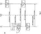
- FIG. 2 depicts a signaling or activity diagram 200 between the AP 110 and an example remote station, such as the STA 130. Communications between the STA 130 and the AP 110 occur through the wireless local area network WLAN 120.
- a pairing session is initiated at activity 205.
- the STA 130 initiates transmission of a media access control (MAC) address to the AP 110 using signal 210.
- MAC media access control
- the AP 110 does not respond until the PBC button 150 of Figure 1 is depressed by a system user as in activity 220.
- the AP 110 hides all SSIDs by turning off the transmission of identifying indicia of the SSIDs related to the AP 110.
- MAC media access control
- remote stations such as STA 140, which may already be linked to the AP, continue to operate without public identification of SSID names.
- the AP examines the MAC address of STA 130 to determine of the STA 130 has permission to gain access to the AP 110. It does this by comparing the incoming MAC address with a list of authorized MAC addresses.
- the SSID of the authorized service for the specific MAC address is transmitted.
- only the SSID of the authorized service for the MAC address of STA 130 is transmitted via signal 240.
- the STA 130 is then able to initiate the pairing process at activity 245 by selecting the available SSID that is compatible with the AP 110.
- the selection of a compatible and authorized SSID is based on the MAC address of the STA and the selection is limited to only the SSID that was made visible by the AP.
- the transmission of SSID is enabled via the association of the MAC address of the STA 130 on the list of service associated with that specific MAC address. This selective transmission avoids the STA 130 selecting a wrong or unsuitable SSID.
- pairing exchanges 250 are performed. Such pairing exchanges may include the exchange of public and private encryption keys, such as "Diffie-Hellman-Merkle" key exchanges.
- the AP 110 is able to finish the pairing to the STA 130 at activity 255.
- the pairing process is considered complete and all previous transmissions of SSIDs from the AP 110 are restored at signaling 260.
- Data exchanges between the AP 110 and the newly paired STA 130 may now take place as example data exchanges 265.
- the WPS PBC method of Figure 2 only involves the interaction of two active machines: the AP 110 and the STA 130 across the WLAN 120.
- a physical push button 150 is used.
- a logical push button signaling is also possible according to aspects of the invention.
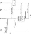
- FIG. 3 depicts a signaling or activity diagram 300 between a personal computer 170 (PC), an AP 110, and a STA 130.
- This signaling scheme involves a logical PBC method instead of a physical PBC method.
- the PC 170 is used to select an SSID for a WLAN accessible service for STA 130 that is available via AP 110.
- the selection of SSID for the STA 130, which has no communicative connection to the WLAN 120, is performed at activity 305.
- signal 310 is sent which includes the SSID selection.
- the signaling 310 is sent from the PC 170 to the AP 110.
- the AP acts with signal 320 to hide all SSIDs except for the selected SSID. Hiding all SSIDs except the selected SSID for STA 130 permits STA 130 to easily select the correct SSID at activity 325.
- the STA 130 at 325 initiates the pairing activity by selecting the transmitted SSID without having to make a selection from a multitude of SSIDs. Hiding all SSIDs except for the selected SSID for STA 130 guarantees that STA 130 does not connect to an incorrect SSID. In prior systems, STA 130 would have to select which SSID it wanted to pair with because all SSIDs may be transmitted in the WPS PBC process. This can lead to the STA 130 pairing with an incorrect SSID or a STA 310 PBC overlap pairing failure. However, the improved technique represented in Figure 3 ensures that the STA 130 pairs with only the selected and authorized SSID.
- the PC 170 sends a logical push button activation signal to the AP 110 via signal 330.
- Signal 330 is detected by the AP 110 as a logical button press at activity 335.
- This activity also initiates pairing signal exchanges 340.
- pairing exchanges may include the exchange of public and private encryption keys, such as "Diffie-Hellman-Merkle" key exchanges.
- the AP 110 is able to finish the pairing to the STA 130 at activity 345.
- the pairing process is considered complete and SSID transmissions from the AP 110 are restored at signaling 350.
- Data exchanges between the AP 110 and the paired STA 130 may now take place as example data exchanges 355.
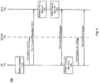
- Figure 4 depicts a signaling or activity diagram 700 between the AP 110 and an example remote station, such as the STA 130. Communications between the STA 130 and the AP 110 occur through the wireless local area network WLAN 120.
- a physical button on the AP110 is pressed. In one embodiment, the physical button is pressed a number of times, such as three times, to indicate that a specific SSID is to be chosen. In an alternate embodiment, a special physical button is pressed to indicate a specific SSID selection. In either event, the AP 110 interprets the button pressing as the selection of a pre-selected SSID for pairing with STA 130.
- the AP 110 hides all SSIDs by turning off the transmission of identifying indicia of the SSIDs related to the AP 110. During this time, remote stations, such as STA 140, which may already be linked to the AP, continue to operate without public identification of SSID names.
- the STA 130 is then able to initiate the pairing process at activity 725 by selecting the only available SSID whose identity is transmitted by the AP 110.
- the selection of a compatible and authorized SSID is limited to only the SSID that was made visible by the AP. This selective transmission avoids the STA 130 selecting a wrong or unsuitable SSID.
- the STA 130 initiates pairing with the AP 110.
- pairing exchanges 735 are performed.
- Such pairing exchanges may include the exchange of public and private encryption keys, such as "Diffie-Hellman-Merkle" key exchanges.
- the AP 110 is able to finish the pairing to the STA 130 at activity 740.
- the pairing process is considered complete and all previous transmissions of SSIDs from the AP 110 are restored at signaling 745.
- Data exchanges between the AP 110 and the newly paired STA 130 may now take place as example data exchanges 750.
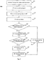
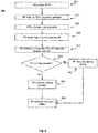
- FIG. 5 is an example method 400 that uses an improved WPS PBC physical pushbutton according to aspects of the invention.
- Figure 5 is an example method that utilizes the example signal flow of Figure 2 .
- the method 400 includes a wireless device, such as STA 130, and an access point, such as AP 110.
- the STA 130 activates a pairing request. This request is accomplished via use of a user interface on the STA 130 requesting access to the WLAN 120 via the AP 100.
- an identity indication of the STA 130 is provided to the AP 110.
- the identity indication is a MAC address. This MAC address may be part of a beacon message where the wireless station, seeking to operate on an IEEE 802.11 WLAN, starts transmitting beacon messages to the AP.
- the AP 110 receives the pairing request and MAC address of the STA 130 at step 405.
- the AP 110 receives a push button configuration control command via an activation of the push button on the AP 110, such as push button 150 of Figure 1 .
- the activation of the push button provides a push button command to the AP 110 to pair the wireless device, such as STA 130, to the AP.
- Receiving a push button command at the AP includes receiving an indication at the access point that the pairing button, such as button 150 of Figure 1 , has been activated.
- the AP acts to inhibit broadcasting of all SSIDs associated with the AP. This inhibition or ceasing of transmission of all SSIDs from the AP provides an indication that the present improved WiFiTM or wireless protected setup (WPS) has commenced. In contrast to a conventional WPS method where all SSIDs may be transmitted, method 400 hides all SSIDs by ceasing the broadcasting of all SSIDs associated with the AP.
- the AP determines if the wireless device, such as a STA is permitted to pair with the AP. This step includes comparing an identifier indicator, such as a MAC address, of the wireless device with a listing of SSIDs and wireless device indicators. Pairing of the wireless device is permitted if the wireless device indicator corresponds to an approved device for AP access on the listing of SSIDs and wireless device indicators.
- step 435 is performed.
- Step 435 is a step which can indicate, via screen display, LED illumination, printing or logging that pairing of the wireless device with the AP has failed.
- step 445 is undertaken which restores all of the normally transmitted SSID broadcasts.
- step 425 is performed. Step 425 broadcasts only the SSID that is associated with the wireless device that seeks access to the AP. This step ensures that the wireless device only sees a compatible and authorized SSID available for pairing.
- the wireless station is prevented from erroneously pairing with a SSID that is not compatible or authorized for pair with the wireless station.
- the broadcasting of only the selected SSID ensures that the wireless device pairs with only a correct service set identifier.
- step 430 the AP and wireless device attempt a pairing using the SSID that is broadcast to the wireless station.
- the pairing process includes exchanging security keys between the AP and the wireless device.
- pairing signal exchanges include public and private encryption key exchanges, such as "Diffie-Hellman-Merkle" key exchanges. If the pairing fails, step 435 and 445 are performed. If the pairing succeeds, then step 440 may be performed in which the AP provides an indication, such as display on a screen or an LED, print, or data logging, of the pairing success. Then, step 445 is performed to restore all of the previously broadcast SSIDs associated with the AP. The wireless device and the AP then can exchange data as would be normal for a paired AP and wireless device communicating over a WLAN.
- FIG. 6 is an example method 500 that uses an improved WPS PBC logical pushbutton according to aspects of the invention.
- Figure 6 is an example method that utilizes the example signal diagram of Figure 3 .
- the method 500 includes a terminal, such as personal computer 170, a wireless device, such as STA 130, and an access point, such as AP 110.
- the PC 170 may have a wired connection to the AP, such as shown in Figure 1 , or may be connected via an RF interface, such as via WLAN 120 using a protocol such as IEEE 802.11.
- the PC is provided a selection of an SSID for the wireless station, such as STA 130, so that the wireless station can operate on the WLAN of the AP.
- a user of the PC can provide the selection of SSID.
- a request for the addition of the wireless station to an SSID is provided to the AP by the PC.
- the AP hides all SSIDs except for the requested SSID selection made by the PC. Hiding all SSIDs from the pairing wireless device, STA 130, prevents pairing of the wireless device to a service set identifier that is not associated with the wireless device. Stated another way, the broadcasting of only the selected SSID ensures that the wireless device pairs with only a correct service set identifier.
- the wireless station activates a pairing request.
- This pairing request activation can be accomplished using a user interface on the wireless device so that pairing of the wireless device to the AP is initiated.
- the AP receives a logical push button configuration activation signal (logical push button press) from the PC.
- Receiving a logical push button configuration activation from the PC includes receiving a signal indication from the PC that a logical push button activation is initiated. The AP detects this logical activation signal.
- the AP attempts pairing with the wireless device. Pairing includes exchanging security keys between the AP and the wireless device.
- pairing signal exchanges include public and private encryption key exchanges, such as "Diffie-Hellman-Merkle" key exchanges.
- the AP can activate wireless pairing session indicators if available. These indicators can be a display, such as a screen display or a LED illumination, a printing, or a logging of pairing activity.
- the AP assesses if the pairing has succeeded. If the pairing did not succeed, then step 545 can indicate a pairing process failure. Such a failure indication can include a display on a screen or an LED, print, or data logging, of the pairing failure.
- the AP can then restore the broadcasting of all SSIDs via step 550. If the pairing assessment of step 530 is positive, then the AP may indicate, if available an indication of pairing success. Such an indication can include a display on a screen or an LED, print, or data logging, of the pairing success. Once the status of the pairing is known, then the AP performs step 550 by restoring the broadcasting of all active SSIDs of the AP. This signifies the end of the pairing process and the continuation of normal exchanges of data and other information between the access point and the wireless device across the wireless network.
- Figure 7 is an example method 800 that uses an improved physical pushbutton configuration method according to aspects of the invention.
- Figure 7 is an example method that utilizes the example signal flow of Figure 4 .
- the method 800 includes a wireless device, such as STA 130, and an access point, such as AP 110.
- a wireless device such as STA 130
- AP 110 an access point
- successive presses or activations of a physical pairing button on the AP 110 are made in a given time interval.
- An example time interval is 10 seconds. However other time intervals can also be used such as 5, 15, or 20 seconds.
- a special, dedicated push button on the AP 110 may be pressed.
- the AP 110 is alerted to the fact that a specific SSID is to be used for pairing.
- This specific SSID may be preselected within the AP 110 so that a specific wireless station, such as STA 130, can be paired with only the AP selected SSID.
- the AP acts to inhibit broadcasting of all SSIDs associated with the AP. This inhibition or ceasing of transmission of all SSIDs from the AP 110.
- method 800 hides all SSIDs by ceasing the broadcasting of all SSIDs associated with the AP.
- Step 815 broadcasts only the SSID that is associated with the wireless device that seeks access to the AP. This step ensures that the wireless device only sees a compatible and authorized SSID available for pairing. Thus, the wireless station is prevented from erroneously pairing with a SSID that is not compatible or authorized for pair with the wireless station. Stated another way, the broadcasting of only the selected SSID ensures that the wireless device pairs with only a correct service set identifier.
- step 820 the AP and wireless device attempt a pairing using the SSID that is broadcast to the wireless station.
- the pairing process includes exchanging security keys between the AP and the wireless device.
- pairing signal exchanges include public and private encryption key exchanges, such as "Diffie-Hellman-Merkle" key exchanges. If the pairing fails, step 825 and 835 are performed. If the pairing succeeds, then step 830 may be performed in which the AP provides an indication, such as display on a screen or an LED, print, or data logging, of the pairing success. Then, step 835 is performed to restore all of the previously broadcast SSIDs associated with the AP. The wireless device and the AP then can exchange data as would be normal for a paired AP and wireless device communicating over a WLAN.
- FIG 8 is an example embodiment of an AP, such as that shown in Figure 1 , item 110.
- a connection to a core network 160 is via the network transmitter/receiver interface 602.
- the core network 160 connection referred to here may include a connection to the internet or other resources which may include servers, remote or cloud memory, or other possible network services.
- the core network interface 602 connects to the bus interface 604 which allows access to the internal bus 624.
- bus 624 are also possible as is well known to those of skill in the art.
- a storage device 606 which can be used for any general storage such as retrieved or requested data and network management data, parameters, and programs. Such network management and other programs are under the control of controller/processor 608.
- This controller/processor 608 may be a single processor or a multiplicity of processors performing the tasks of network management, user interface control, and resource managements.
- Control memory 610 can supply program instruction and configuration control for controller/processor 608.
- the user interface 618 allows a user, network owner, or network manager to see a status of the AP 110. Such indicators may include a display, LEDs, printer interface, or data logging interface.
- An input/output (I/O) interface 616 allows the AP 110 to connect to a personal computer or other device that can be used to configure and control the AP.
- the I/O interface 616 may be a hardline interface, such as an Ethernet interface or may operationally be substituted with an RF interface so that the AP 110 can communicate with a PC via a protocol driven interface, such as IEEE 802.XX. Alternately, a remote terminal, such as PC 160 may also be connected to a WLAN operated by the AP.
- a protocol driven interface such as IEEE 802.XX.
- PC 160 may also be connected to a WLAN operated by the AP.
- Other interfaces that are possible via I/O interface 616 are an interactive interface which may include the use of a display device, keyboard, mouse, light pen, and the like.
- AP 110 has a wireless network interface 612 which allows access to and from regular users to the resources of the core network 160. Such an interface includes all elements to control a wireless network, including the use of wireless network protocols such as IEEE 802.XX and the like.
- the controller/processor 608 of the AP 110 of Figure 6 is configured to provide processing services for the steps of the methods of Figures 4 and 5 .
- the controller processor can provide instruction control to monitor and control the interfaces of the network transmitter/receiver 602, the I/O interfaces 616 and 618, and the WLAN interface 612. Controller/processor 608 directs the flow of information through AP 110 such that the AP activities of signal Figures 2 and 3 are performed as well as the method of Figures 4 and 5 .
- implementations described herein may be implemented in, for example, a method or process, an apparatus, or a combination of hardware and software. Even if only discussed in the context of a single form of implementation (for example, discussed only as a method), the implementation of features discussed may also be implemented in other forms. For example, implementation can be accomplished via a hardware apparatus, hardware and software apparatus. An apparatus may be implemented in, for example, appropriate hardware, software, and firmware. The methods may be implemented in, for example, an apparatus such as, for example, a processor, which refers to any processing device, including, for example, a computer, a microprocessor, an integrated circuit, or a programmable logic device.
- the methods may be implemented by instructions being performed by a processor, and such instructions may be stored on a processor or computer-readable media such as, for example, an integrated circuit, a software carrier or other storage device such as, for example, a hard disk, a compact diskette ("CD” or “DVD"), a random access memory (“RAM”), a read-only memory (“ROM”) or any other magnetic, optical, or solid state media.
- the instructions may form an application program tangibly embodied on a computer-readable medium such as any of the media listed above or known to those of skill in the art.
- the instructions thus stored are useful to execute elements of hardware and software to perform the steps of the method described herein.
Landscapes
- Engineering & Computer Science (AREA)
- Computer Networks & Wireless Communication (AREA)
- Signal Processing (AREA)
- Computer Security & Cryptography (AREA)
- Mobile Radio Communication Systems (AREA)
Applications Claiming Priority (2)
| Application Number | Priority Date | Filing Date | Title |
|---|---|---|---|
| US201462083377P | 2014-11-24 | 2014-11-24 | |
| PCT/US2015/055740 WO2016085582A1 (en) | 2014-11-24 | 2015-10-15 | Method and apparatus for wlan device pairing |
Publications (2)
| Publication Number | Publication Date |
|---|---|
| EP3225054A1 EP3225054A1 (en) | 2017-10-04 |
| EP3225054B1 true EP3225054B1 (en) | 2019-06-19 |
Family
ID=54477235
Family Applications (1)
| Application Number | Title | Priority Date | Filing Date |
|---|---|---|---|
| EP15791073.8A Active EP3225054B1 (en) | 2014-11-24 | 2015-10-15 | Method and apparatus for wlan device pairing |
Country Status (6)
Families Citing this family (11)
| Publication number | Priority date | Publication date | Assignee | Title |
|---|---|---|---|---|
| JP2017130839A (ja) * | 2016-01-21 | 2017-07-27 | キヤノン株式会社 | 通信装置、通信制御方法及びプログラム |
| DE102016221614A1 (de) | 2016-11-04 | 2018-05-09 | BSH Hausgeräte GmbH | Verbinden eines Haushaltsgeräts mit einer Fernbedienung |
| JP7009964B2 (ja) * | 2017-12-06 | 2022-01-26 | ブラザー工業株式会社 | 通信装置 |
| EP3547757A1 (en) * | 2018-03-30 | 2019-10-02 | InterDigital CE Patent Holdings | Wireless access point and method for providing backup network connections |
| JP2019186878A (ja) * | 2018-04-17 | 2019-10-24 | 村田機械株式会社 | 無線lanアクセスポイント装置 |
| WO2020006665A1 (en) * | 2018-07-02 | 2020-01-09 | Orange | Method for connecting an electronic device to a target wireless access point |
| JP7189419B2 (ja) * | 2018-08-09 | 2022-12-14 | ダイキン工業株式会社 | 冷凍システム及び無線lanアダプタ |
| US11616784B2 (en) * | 2019-07-11 | 2023-03-28 | Kyndryl, Inc. | Personal-public service set identifiers connection implemented by a WAP |
| FR3100098B1 (fr) * | 2019-08-21 | 2021-07-23 | Sagemcom Broadband Sas | Procedes et dispositifs d’appairage dans un reseau sans-fil |
| WO2021163870A1 (en) * | 2020-02-18 | 2021-08-26 | Arris Enterprises Llc | Onboarding of devices to different wireless networks |
| CN112929908B (zh) * | 2021-03-17 | 2023-03-24 | 北京小米移动软件有限公司 | Mesh组网方法、装置、网关设备及存储介质 |
Family Cites Families (20)
| Publication number | Priority date | Publication date | Assignee | Title |
|---|---|---|---|---|
| US7339915B2 (en) * | 2005-10-11 | 2008-03-04 | Cisco Technology, Inc. | Virtual LAN override in a multiple BSSID mode of operation |
| JP4273113B2 (ja) * | 2005-11-25 | 2009-06-03 | Necアクセステクニカ株式会社 | 無線lan装置認証方法及びシステム、並びに無線lan装置認証用プログラム |
| EP1928125B1 (en) * | 2006-11-30 | 2012-07-18 | Research In Motion Limited | Determining Identifiers for Wireless Networks with Hidden Identifiers |
| KR20090113033A (ko) * | 2008-04-25 | 2009-10-29 | 삼성전자주식회사 | 기기의 무선 랜 설정 방법 및 장치 |
| JP5538692B2 (ja) * | 2008-08-08 | 2014-07-02 | キヤノン株式会社 | 通信装置、通信装置の制御方法、コンピュータプログラム |
| KR101733242B1 (ko) | 2010-03-31 | 2017-05-08 | 삼성전자주식회사 | 무선 통신 시스템에서의 자동 접속 장치 및 방법 |
| US8925042B2 (en) * | 2010-04-30 | 2014-12-30 | T-Mobile Usa, Inc. | Connecting devices to an existing secure wireless network |
| US20110276672A1 (en) | 2010-05-07 | 2011-11-10 | Samsung Electronics Co., Ltd. | Method and apparatus for performing pairing between coordinator and device in network, method and apparatus for performing pairing between devices, network system including the coordinator and the devices |
| WO2011161950A1 (ja) * | 2010-06-21 | 2011-12-29 | パナソニック株式会社 | アクセスポイント端末、無線通信端末、無線通信システム、無線通信方法、プログラム、及び集積回路 |
| CN101873720A (zh) * | 2010-06-28 | 2010-10-27 | 华为终端有限公司 | 建立无线连接的方法及无线接入设备 |
| US8531989B2 (en) | 2011-03-08 | 2013-09-10 | Qualcomm Incorporated | Systems and methods for implementing ad hoc wireless networking |
| JP5708370B2 (ja) * | 2011-08-24 | 2015-04-30 | 富士通モバイルコミュニケーションズ株式会社 | 無線通信装置 |
| JP2013055463A (ja) * | 2011-09-02 | 2013-03-21 | Canon Inc | 無線設定制御装置、その制御方法、および制御プログラム |
| US20130272164A1 (en) | 2012-04-17 | 2013-10-17 | Econais Ae | Systems and methods of wi-fi enabled device configuration |
| KR20140088354A (ko) * | 2013-01-02 | 2014-07-10 | 삼성전자주식회사 | 무선 액세스 포인트 접속 운용 방법 및 이를 지원하는 단말기 |
| US20140328334A1 (en) | 2013-05-03 | 2014-11-06 | Gainspan Corporation | Provisioning a wireless device for secure communication using an access point designed with push-button mode of wps (wi-fi protected setup) |
| TWI669972B (zh) * | 2013-08-29 | 2019-08-21 | 內數位專利控股公司 | 無線網路選擇方法、裝置及系統 |
| CN104093164A (zh) * | 2014-07-17 | 2014-10-08 | 杭州古北电子科技有限公司 | 无线网接入的控制方法及其系统 |
| CN104144463B (zh) * | 2014-08-19 | 2017-08-11 | 天津三星通信技术研究有限公司 | Wi‑Fi网络接入方法和系统 |
| US10075906B2 (en) * | 2014-11-19 | 2018-09-11 | At&T Intellectual Property I, L.P. | Facilitating dynamic private communication networks |
-
2015
- 2015-10-15 EP EP15791073.8A patent/EP3225054B1/en active Active
- 2015-10-15 WO PCT/US2015/055740 patent/WO2016085582A1/en active Application Filing
- 2015-10-15 US US15/528,967 patent/US10681749B2/en active Active
- 2015-10-15 JP JP2017527298A patent/JP6647300B2/ja active Active
- 2015-10-15 CN CN201580065217.3A patent/CN107005921B/zh active Active
- 2015-10-15 KR KR1020177014010A patent/KR102297889B1/ko active Active
Non-Patent Citations (1)
| Title |
|---|
| None * |
Also Published As
| Publication number | Publication date |
|---|---|
| JP2017536046A (ja) | 2017-11-30 |
| US10681749B2 (en) | 2020-06-09 |
| CN107005921B (zh) | 2020-07-28 |
| US20170273123A1 (en) | 2017-09-21 |
| KR102297889B1 (ko) | 2021-09-03 |
| WO2016085582A1 (en) | 2016-06-02 |
| EP3225054A1 (en) | 2017-10-04 |
| CN107005921A (zh) | 2017-08-01 |
| JP6647300B2 (ja) | 2020-02-14 |
| BR112017010884A2 (pt) | 2018-01-09 |
| KR20170087888A (ko) | 2017-07-31 |
Similar Documents
| Publication | Publication Date | Title |
|---|---|---|
| EP3225054B1 (en) | Method and apparatus for wlan device pairing | |
| US11863556B2 (en) | Configuring access for internet-of-things and limited user interface devices | |
| US8199699B2 (en) | Legacy support for Wi-Fi protected setup | |
| US20100146129A1 (en) | Communication apparatus and method for wi-fi protected setup in adhoc network | |
| US20140369239A1 (en) | Network configuration for devices with constrained resources | |
| US9270640B2 (en) | Communication device, control method for communication device, and storage medium | |
| EP2817992B1 (en) | Method and network node device for controlling the run of technology specific push-button configuration sessions within a heterogeneous or homogeneous wireless network and heterogeneous or homogeneous wireless network | |
| US7650411B2 (en) | Method and system for secure management and communication utilizing configuration network setup in a WLAN | |
| EP2826304B1 (en) | Method and system for preventing the propagation of ad -hoc networks | |
| US20190104422A1 (en) | System and Method for Easy Configuration and Authentication of Network Devices | |
| CN112188488A (zh) | 一种配网方法、装置及系统 | |
| CN111818528B (zh) | 无线局域网的连接方法、装置、存储介质及无线接入设备 | |
| US20250142335A1 (en) | Systems and methods for virtual personal wi-fi network | |
| US9247431B2 (en) | Communication apparatus, control method of communication apparatus, and program | |
| CN103297952B (zh) | 一种双频wps触发方法 | |
| CN110024443B (zh) | 用于与网关配对的方法 | |
| US10779166B2 (en) | Technique for controlling access to a radio access network | |
| JP5246029B2 (ja) | 無線通信システム | |
| JP6844892B2 (ja) | 無線lanネットワーク、無線lanクライアント端末、ならびに無線lan接続設定方法およびプログラム | |
| BR112017010884B1 (pt) | Método e mídia de armazenamento legível por computador para parear um novo dispositivo sem fio a um ponto de acesso e ponto de acesso para parear com um novo dispositivo sem fio | |
| US20110013610A1 (en) | Communication method and wireless apparatus using the communication method | |
| GB2531711A (en) | Authentication system and method of authentication |
Legal Events
| Date | Code | Title | Description |
|---|---|---|---|
| STAA | Information on the status of an ep patent application or granted ep patent |
Free format text: STATUS: THE INTERNATIONAL PUBLICATION HAS BEEN MADE |
|
| PUAI | Public reference made under article 153(3) epc to a published international application that has entered the european phase |
Free format text: ORIGINAL CODE: 0009012 |
|
| STAA | Information on the status of an ep patent application or granted ep patent |
Free format text: STATUS: REQUEST FOR EXAMINATION WAS MADE |
|
| 17P | Request for examination filed |
Effective date: 20170621 |
|
| AK | Designated contracting states |
Kind code of ref document: A1 Designated state(s): AL AT BE BG CH CY CZ DE DK EE ES FI FR GB GR HR HU IE IS IT LI LT LU LV MC MK MT NL NO PL PT RO RS SE SI SK SM TR |
|
| AX | Request for extension of the european patent |
Extension state: BA ME |
|
| DAV | Request for validation of the european patent (deleted) | ||
| DAX | Request for extension of the european patent (deleted) | ||
| GRAP | Despatch of communication of intention to grant a patent |
Free format text: ORIGINAL CODE: EPIDOSNIGR1 |
|
| STAA | Information on the status of an ep patent application or granted ep patent |
Free format text: STATUS: GRANT OF PATENT IS INTENDED |
|
| INTG | Intention to grant announced |
Effective date: 20181214 |
|
| RAP1 | Party data changed (applicant data changed or rights of an application transferred) |
Owner name: INTERDIGITAL CE PATENT HOLDINGS |
|
| GRAJ | Information related to disapproval of communication of intention to grant by the applicant or resumption of examination proceedings by the epo deleted |
Free format text: ORIGINAL CODE: EPIDOSDIGR1 |
|
| STAA | Information on the status of an ep patent application or granted ep patent |
Free format text: STATUS: REQUEST FOR EXAMINATION WAS MADE |
|
| GRAR | Information related to intention to grant a patent recorded |
Free format text: ORIGINAL CODE: EPIDOSNIGR71 |
|
| GRAS | Grant fee paid |
Free format text: ORIGINAL CODE: EPIDOSNIGR3 |
|
| STAA | Information on the status of an ep patent application or granted ep patent |
Free format text: STATUS: GRANT OF PATENT IS INTENDED |
|
| INTC | Intention to grant announced (deleted) | ||
| GRAA | (expected) grant |
Free format text: ORIGINAL CODE: 0009210 |
|
| STAA | Information on the status of an ep patent application or granted ep patent |
Free format text: STATUS: THE PATENT HAS BEEN GRANTED |
|
| INTG | Intention to grant announced |
Effective date: 20190508 |
|
| AK | Designated contracting states |
Kind code of ref document: B1 Designated state(s): AL AT BE BG CH CY CZ DE DK EE ES FI FR GB GR HR HU IE IS IT LI LT LU LV MC MK MT NL NO PL PT RO RS SE SI SK SM TR |
|
| REG | Reference to a national code |
Ref country code: GB Ref legal event code: FG4D |
|
| REG | Reference to a national code |
Ref country code: CH Ref legal event code: EP |
|
| REG | Reference to a national code |
Ref country code: IE Ref legal event code: FG4D |
|
| REG | Reference to a national code |
Ref country code: DE Ref legal event code: R096 Ref document number: 602015032361 Country of ref document: DE |
|
| REG | Reference to a national code |
Ref country code: AT Ref legal event code: REF Ref document number: 1147116 Country of ref document: AT Kind code of ref document: T Effective date: 20190715 |
|
| REG | Reference to a national code |
Ref country code: NL Ref legal event code: FP |
|
| PG25 | Lapsed in a contracting state [announced via postgrant information from national office to epo] |
Ref country code: HR Free format text: LAPSE BECAUSE OF FAILURE TO SUBMIT A TRANSLATION OF THE DESCRIPTION OR TO PAY THE FEE WITHIN THE PRESCRIBED TIME-LIMIT Effective date: 20190619 Ref country code: SE Free format text: LAPSE BECAUSE OF FAILURE TO SUBMIT A TRANSLATION OF THE DESCRIPTION OR TO PAY THE FEE WITHIN THE PRESCRIBED TIME-LIMIT Effective date: 20190619 Ref country code: LT Free format text: LAPSE BECAUSE OF FAILURE TO SUBMIT A TRANSLATION OF THE DESCRIPTION OR TO PAY THE FEE WITHIN THE PRESCRIBED TIME-LIMIT Effective date: 20190619 Ref country code: NO Free format text: LAPSE BECAUSE OF FAILURE TO SUBMIT A TRANSLATION OF THE DESCRIPTION OR TO PAY THE FEE WITHIN THE PRESCRIBED TIME-LIMIT Effective date: 20190919 Ref country code: AL Free format text: LAPSE BECAUSE OF FAILURE TO SUBMIT A TRANSLATION OF THE DESCRIPTION OR TO PAY THE FEE WITHIN THE PRESCRIBED TIME-LIMIT Effective date: 20190619 Ref country code: FI Free format text: LAPSE BECAUSE OF FAILURE TO SUBMIT A TRANSLATION OF THE DESCRIPTION OR TO PAY THE FEE WITHIN THE PRESCRIBED TIME-LIMIT Effective date: 20190619 |
|
| REG | Reference to a national code |
Ref country code: LT Ref legal event code: MG4D |
|
| PG25 | Lapsed in a contracting state [announced via postgrant information from national office to epo] |
Ref country code: BG Free format text: LAPSE BECAUSE OF FAILURE TO SUBMIT A TRANSLATION OF THE DESCRIPTION OR TO PAY THE FEE WITHIN THE PRESCRIBED TIME-LIMIT Effective date: 20190919 Ref country code: RS Free format text: LAPSE BECAUSE OF FAILURE TO SUBMIT A TRANSLATION OF THE DESCRIPTION OR TO PAY THE FEE WITHIN THE PRESCRIBED TIME-LIMIT Effective date: 20190619 Ref country code: GR Free format text: LAPSE BECAUSE OF FAILURE TO SUBMIT A TRANSLATION OF THE DESCRIPTION OR TO PAY THE FEE WITHIN THE PRESCRIBED TIME-LIMIT Effective date: 20190920 Ref country code: LV Free format text: LAPSE BECAUSE OF FAILURE TO SUBMIT A TRANSLATION OF THE DESCRIPTION OR TO PAY THE FEE WITHIN THE PRESCRIBED TIME-LIMIT Effective date: 20190619 |
|
| REG | Reference to a national code |
Ref country code: AT Ref legal event code: MK05 Ref document number: 1147116 Country of ref document: AT Kind code of ref document: T Effective date: 20190619 |
|
| PG25 | Lapsed in a contracting state [announced via postgrant information from national office to epo] |
Ref country code: EE Free format text: LAPSE BECAUSE OF FAILURE TO SUBMIT A TRANSLATION OF THE DESCRIPTION OR TO PAY THE FEE WITHIN THE PRESCRIBED TIME-LIMIT Effective date: 20190619 Ref country code: PT Free format text: LAPSE BECAUSE OF FAILURE TO SUBMIT A TRANSLATION OF THE DESCRIPTION OR TO PAY THE FEE WITHIN THE PRESCRIBED TIME-LIMIT Effective date: 20191021 Ref country code: AT Free format text: LAPSE BECAUSE OF FAILURE TO SUBMIT A TRANSLATION OF THE DESCRIPTION OR TO PAY THE FEE WITHIN THE PRESCRIBED TIME-LIMIT Effective date: 20190619 Ref country code: SK Free format text: LAPSE BECAUSE OF FAILURE TO SUBMIT A TRANSLATION OF THE DESCRIPTION OR TO PAY THE FEE WITHIN THE PRESCRIBED TIME-LIMIT Effective date: 20190619 Ref country code: CZ Free format text: LAPSE BECAUSE OF FAILURE TO SUBMIT A TRANSLATION OF THE DESCRIPTION OR TO PAY THE FEE WITHIN THE PRESCRIBED TIME-LIMIT Effective date: 20190619 Ref country code: RO Free format text: LAPSE BECAUSE OF FAILURE TO SUBMIT A TRANSLATION OF THE DESCRIPTION OR TO PAY THE FEE WITHIN THE PRESCRIBED TIME-LIMIT Effective date: 20190619 |
|
| PG25 | Lapsed in a contracting state [announced via postgrant information from national office to epo] |
Ref country code: IS Free format text: LAPSE BECAUSE OF FAILURE TO SUBMIT A TRANSLATION OF THE DESCRIPTION OR TO PAY THE FEE WITHIN THE PRESCRIBED TIME-LIMIT Effective date: 20191019 Ref country code: ES Free format text: LAPSE BECAUSE OF FAILURE TO SUBMIT A TRANSLATION OF THE DESCRIPTION OR TO PAY THE FEE WITHIN THE PRESCRIBED TIME-LIMIT Effective date: 20190619 Ref country code: SM Free format text: LAPSE BECAUSE OF FAILURE TO SUBMIT A TRANSLATION OF THE DESCRIPTION OR TO PAY THE FEE WITHIN THE PRESCRIBED TIME-LIMIT Effective date: 20190619 |
|
| PG25 | Lapsed in a contracting state [announced via postgrant information from national office to epo] |
Ref country code: TR Free format text: LAPSE BECAUSE OF FAILURE TO SUBMIT A TRANSLATION OF THE DESCRIPTION OR TO PAY THE FEE WITHIN THE PRESCRIBED TIME-LIMIT Effective date: 20190619 |
|
| PG25 | Lapsed in a contracting state [announced via postgrant information from national office to epo] |
Ref country code: DK Free format text: LAPSE BECAUSE OF FAILURE TO SUBMIT A TRANSLATION OF THE DESCRIPTION OR TO PAY THE FEE WITHIN THE PRESCRIBED TIME-LIMIT Effective date: 20190619 Ref country code: PL Free format text: LAPSE BECAUSE OF FAILURE TO SUBMIT A TRANSLATION OF THE DESCRIPTION OR TO PAY THE FEE WITHIN THE PRESCRIBED TIME-LIMIT Effective date: 20190619 |
|
| PG25 | Lapsed in a contracting state [announced via postgrant information from national office to epo] |
Ref country code: MC Free format text: LAPSE BECAUSE OF FAILURE TO SUBMIT A TRANSLATION OF THE DESCRIPTION OR TO PAY THE FEE WITHIN THE PRESCRIBED TIME-LIMIT Effective date: 20190619 Ref country code: IS Free format text: LAPSE BECAUSE OF FAILURE TO SUBMIT A TRANSLATION OF THE DESCRIPTION OR TO PAY THE FEE WITHIN THE PRESCRIBED TIME-LIMIT Effective date: 20200224 |
|
| REG | Reference to a national code |
Ref country code: CH Ref legal event code: PL |
|
| REG | Reference to a national code |
Ref country code: DE Ref legal event code: R097 Ref document number: 602015032361 Country of ref document: DE |
|
| PLBE | No opposition filed within time limit |
Free format text: ORIGINAL CODE: 0009261 |
|
| STAA | Information on the status of an ep patent application or granted ep patent |
Free format text: STATUS: NO OPPOSITION FILED WITHIN TIME LIMIT |
|
| PG2D | Information on lapse in contracting state deleted |
Ref country code: IS |
|
| PG25 | Lapsed in a contracting state [announced via postgrant information from national office to epo] |
Ref country code: CH Free format text: LAPSE BECAUSE OF NON-PAYMENT OF DUE FEES Effective date: 20191031 Ref country code: LI Free format text: LAPSE BECAUSE OF NON-PAYMENT OF DUE FEES Effective date: 20191031 Ref country code: LU Free format text: LAPSE BECAUSE OF NON-PAYMENT OF DUE FEES Effective date: 20191015 |
|
| 26N | No opposition filed |
Effective date: 20200603 |
|
| REG | Reference to a national code |
Ref country code: BE Ref legal event code: MM Effective date: 20191031 |
|
| PG25 | Lapsed in a contracting state [announced via postgrant information from national office to epo] |
Ref country code: BE Free format text: LAPSE BECAUSE OF NON-PAYMENT OF DUE FEES Effective date: 20191031 Ref country code: SI Free format text: LAPSE BECAUSE OF FAILURE TO SUBMIT A TRANSLATION OF THE DESCRIPTION OR TO PAY THE FEE WITHIN THE PRESCRIBED TIME-LIMIT Effective date: 20190619 |
|
| PG25 | Lapsed in a contracting state [announced via postgrant information from national office to epo] |
Ref country code: FR Free format text: LAPSE BECAUSE OF NON-PAYMENT OF DUE FEES Effective date: 20191031 Ref country code: IE Free format text: LAPSE BECAUSE OF NON-PAYMENT OF DUE FEES Effective date: 20191015 |
|
| PG25 | Lapsed in a contracting state [announced via postgrant information from national office to epo] |
Ref country code: CY Free format text: LAPSE BECAUSE OF FAILURE TO SUBMIT A TRANSLATION OF THE DESCRIPTION OR TO PAY THE FEE WITHIN THE PRESCRIBED TIME-LIMIT Effective date: 20190619 |
|
| PG25 | Lapsed in a contracting state [announced via postgrant information from national office to epo] |
Ref country code: HU Free format text: LAPSE BECAUSE OF FAILURE TO SUBMIT A TRANSLATION OF THE DESCRIPTION OR TO PAY THE FEE WITHIN THE PRESCRIBED TIME-LIMIT; INVALID AB INITIO Effective date: 20151015 Ref country code: MT Free format text: LAPSE BECAUSE OF FAILURE TO SUBMIT A TRANSLATION OF THE DESCRIPTION OR TO PAY THE FEE WITHIN THE PRESCRIBED TIME-LIMIT Effective date: 20190619 |
|
| PG25 | Lapsed in a contracting state [announced via postgrant information from national office to epo] |
Ref country code: MK Free format text: LAPSE BECAUSE OF FAILURE TO SUBMIT A TRANSLATION OF THE DESCRIPTION OR TO PAY THE FEE WITHIN THE PRESCRIBED TIME-LIMIT Effective date: 20190619 |
|
| P01 | Opt-out of the competence of the unified patent court (upc) registered |
Effective date: 20230511 |
|
| PGFP | Annual fee paid to national office [announced via postgrant information from national office to epo] |
Ref country code: NL Payment date: 20241023 Year of fee payment: 10 |
|
| PGFP | Annual fee paid to national office [announced via postgrant information from national office to epo] |
Ref country code: DE Payment date: 20241029 Year of fee payment: 10 |
|
| PGFP | Annual fee paid to national office [announced via postgrant information from national office to epo] |
Ref country code: GB Payment date: 20241022 Year of fee payment: 10 |
|
| PGFP | Annual fee paid to national office [announced via postgrant information from national office to epo] |
Ref country code: IT Payment date: 20241022 Year of fee payment: 10 |