EP3224554B1 - Systems and methods for free and positive defrost - Google Patents
Systems and methods for free and positive defrost Download PDFInfo
- Publication number
- EP3224554B1 EP3224554B1 EP14833359.4A EP14833359A EP3224554B1 EP 3224554 B1 EP3224554 B1 EP 3224554B1 EP 14833359 A EP14833359 A EP 14833359A EP 3224554 B1 EP3224554 B1 EP 3224554B1
- Authority
- EP
- European Patent Office
- Prior art keywords
- compressor
- defrost
- evaporator
- mode
- temperature
- Prior art date
- Legal status (The legal status is an assumption and is not a legal conclusion. Google has not performed a legal analysis and makes no representation as to the accuracy of the status listed.)
- Active
Links
- 238000000034 method Methods 0.000 title claims description 35
- 239000003507 refrigerant Substances 0.000 claims description 43
- 238000010257 thawing Methods 0.000 claims description 30
- 239000012080 ambient air Substances 0.000 claims description 28
- 238000010438 heat treatment Methods 0.000 claims description 19
- 230000002441 reversible effect Effects 0.000 claims description 13
- XLYOFNOQVPJJNP-UHFFFAOYSA-N water Substances O XLYOFNOQVPJJNP-UHFFFAOYSA-N 0.000 claims description 13
- 238000007710 freezing Methods 0.000 claims description 9
- 230000008014 freezing Effects 0.000 claims description 9
- 238000012544 monitoring process Methods 0.000 claims description 7
- 230000001351 cycling effect Effects 0.000 description 13
- 238000012546 transfer Methods 0.000 description 13
- 239000003570 air Substances 0.000 description 11
- 238000001816 cooling Methods 0.000 description 7
- 238000009825 accumulation Methods 0.000 description 2
- 230000003247 decreasing effect Effects 0.000 description 2
- 239000012530 fluid Substances 0.000 description 2
- 230000001681 protective effect Effects 0.000 description 2
- 230000001932 seasonal effect Effects 0.000 description 2
- 230000003213 activating effect Effects 0.000 description 1
- 230000015556 catabolic process Effects 0.000 description 1
- 230000005494 condensation Effects 0.000 description 1
- 238000009833 condensation Methods 0.000 description 1
- 230000001143 conditioned effect Effects 0.000 description 1
- 230000003750 conditioning effect Effects 0.000 description 1
- 239000000498 cooling water Substances 0.000 description 1
- 238000006731 degradation reaction Methods 0.000 description 1
- 238000013461 design Methods 0.000 description 1
- 230000006870 function Effects 0.000 description 1
- 230000000977 initiatory effect Effects 0.000 description 1
- 238000009533 lab test Methods 0.000 description 1
- 239000007788 liquid Substances 0.000 description 1
- 238000005259 measurement Methods 0.000 description 1
- 238000005057 refrigeration Methods 0.000 description 1
Images

Classifications
-
- F—MECHANICAL ENGINEERING; LIGHTING; HEATING; WEAPONS; BLASTING
- F25—REFRIGERATION OR COOLING; COMBINED HEATING AND REFRIGERATION SYSTEMS; HEAT PUMP SYSTEMS; MANUFACTURE OR STORAGE OF ICE; LIQUEFACTION SOLIDIFICATION OF GASES
- F25B—REFRIGERATION MACHINES, PLANTS OR SYSTEMS; COMBINED HEATING AND REFRIGERATION SYSTEMS; HEAT PUMP SYSTEMS
- F25B1/00—Compression machines, plants or systems with non-reversible cycle
- F25B1/10—Compression machines, plants or systems with non-reversible cycle with multi-stage compression
-
- F—MECHANICAL ENGINEERING; LIGHTING; HEATING; WEAPONS; BLASTING
- F25—REFRIGERATION OR COOLING; COMBINED HEATING AND REFRIGERATION SYSTEMS; HEAT PUMP SYSTEMS; MANUFACTURE OR STORAGE OF ICE; LIQUEFACTION SOLIDIFICATION OF GASES
- F25B—REFRIGERATION MACHINES, PLANTS OR SYSTEMS; COMBINED HEATING AND REFRIGERATION SYSTEMS; HEAT PUMP SYSTEMS
- F25B13/00—Compression machines, plants or systems, with reversible cycle
-
- F—MECHANICAL ENGINEERING; LIGHTING; HEATING; WEAPONS; BLASTING
- F25—REFRIGERATION OR COOLING; COMBINED HEATING AND REFRIGERATION SYSTEMS; HEAT PUMP SYSTEMS; MANUFACTURE OR STORAGE OF ICE; LIQUEFACTION SOLIDIFICATION OF GASES
- F25D—REFRIGERATORS; COLD ROOMS; ICE-BOXES; COOLING OR FREEZING APPARATUS NOT OTHERWISE PROVIDED FOR
- F25D21/00—Defrosting; Preventing frosting; Removing condensed or defrost water
- F25D21/02—Detecting the presence of frost or condensate
-
- F—MECHANICAL ENGINEERING; LIGHTING; HEATING; WEAPONS; BLASTING
- F25—REFRIGERATION OR COOLING; COMBINED HEATING AND REFRIGERATION SYSTEMS; HEAT PUMP SYSTEMS; MANUFACTURE OR STORAGE OF ICE; LIQUEFACTION SOLIDIFICATION OF GASES
- F25B—REFRIGERATION MACHINES, PLANTS OR SYSTEMS; COMBINED HEATING AND REFRIGERATION SYSTEMS; HEAT PUMP SYSTEMS
- F25B30/00—Heat pumps
- F25B30/02—Heat pumps of the compression type
-
- F—MECHANICAL ENGINEERING; LIGHTING; HEATING; WEAPONS; BLASTING
- F25—REFRIGERATION OR COOLING; COMBINED HEATING AND REFRIGERATION SYSTEMS; HEAT PUMP SYSTEMS; MANUFACTURE OR STORAGE OF ICE; LIQUEFACTION SOLIDIFICATION OF GASES
- F25B—REFRIGERATION MACHINES, PLANTS OR SYSTEMS; COMBINED HEATING AND REFRIGERATION SYSTEMS; HEAT PUMP SYSTEMS
- F25B47/00—Arrangements for preventing or removing deposits or corrosion, not provided for in another subclass
- F25B47/02—Defrosting cycles
- F25B47/022—Defrosting cycles hot gas defrosting
-
- F—MECHANICAL ENGINEERING; LIGHTING; HEATING; WEAPONS; BLASTING
- F25—REFRIGERATION OR COOLING; COMBINED HEATING AND REFRIGERATION SYSTEMS; HEAT PUMP SYSTEMS; MANUFACTURE OR STORAGE OF ICE; LIQUEFACTION SOLIDIFICATION OF GASES
- F25B—REFRIGERATION MACHINES, PLANTS OR SYSTEMS; COMBINED HEATING AND REFRIGERATION SYSTEMS; HEAT PUMP SYSTEMS
- F25B49/00—Arrangement or mounting of control or safety devices
- F25B49/02—Arrangement or mounting of control or safety devices for compression type machines, plants or systems
- F25B49/022—Compressor control arrangements
-
- F—MECHANICAL ENGINEERING; LIGHTING; HEATING; WEAPONS; BLASTING
- F25—REFRIGERATION OR COOLING; COMBINED HEATING AND REFRIGERATION SYSTEMS; HEAT PUMP SYSTEMS; MANUFACTURE OR STORAGE OF ICE; LIQUEFACTION SOLIDIFICATION OF GASES
- F25D—REFRIGERATORS; COLD ROOMS; ICE-BOXES; COOLING OR FREEZING APPARATUS NOT OTHERWISE PROVIDED FOR
- F25D21/00—Defrosting; Preventing frosting; Removing condensed or defrost water
- F25D21/04—Preventing the formation of frost or condensate
-
- F—MECHANICAL ENGINEERING; LIGHTING; HEATING; WEAPONS; BLASTING
- F25—REFRIGERATION OR COOLING; COMBINED HEATING AND REFRIGERATION SYSTEMS; HEAT PUMP SYSTEMS; MANUFACTURE OR STORAGE OF ICE; LIQUEFACTION SOLIDIFICATION OF GASES
- F25B—REFRIGERATION MACHINES, PLANTS OR SYSTEMS; COMBINED HEATING AND REFRIGERATION SYSTEMS; HEAT PUMP SYSTEMS
- F25B2313/00—Compression machines, plants or systems with reversible cycle not otherwise provided for
- F25B2313/029—Control issues
- F25B2313/0294—Control issues related to the outdoor fan, e.g. controlling speed
-
- F—MECHANICAL ENGINEERING; LIGHTING; HEATING; WEAPONS; BLASTING
- F25—REFRIGERATION OR COOLING; COMBINED HEATING AND REFRIGERATION SYSTEMS; HEAT PUMP SYSTEMS; MANUFACTURE OR STORAGE OF ICE; LIQUEFACTION SOLIDIFICATION OF GASES
- F25B—REFRIGERATION MACHINES, PLANTS OR SYSTEMS; COMBINED HEATING AND REFRIGERATION SYSTEMS; HEAT PUMP SYSTEMS
- F25B2313/00—Compression machines, plants or systems with reversible cycle not otherwise provided for
- F25B2313/031—Sensor arrangements
- F25B2313/0315—Temperature sensors near the outdoor heat exchanger
-
- F—MECHANICAL ENGINEERING; LIGHTING; HEATING; WEAPONS; BLASTING
- F25—REFRIGERATION OR COOLING; COMBINED HEATING AND REFRIGERATION SYSTEMS; HEAT PUMP SYSTEMS; MANUFACTURE OR STORAGE OF ICE; LIQUEFACTION SOLIDIFICATION OF GASES
- F25B—REFRIGERATION MACHINES, PLANTS OR SYSTEMS; COMBINED HEATING AND REFRIGERATION SYSTEMS; HEAT PUMP SYSTEMS
- F25B2347/00—Details for preventing or removing deposits or corrosion
- F25B2347/02—Details of defrosting cycles
-
- F—MECHANICAL ENGINEERING; LIGHTING; HEATING; WEAPONS; BLASTING
- F25—REFRIGERATION OR COOLING; COMBINED HEATING AND REFRIGERATION SYSTEMS; HEAT PUMP SYSTEMS; MANUFACTURE OR STORAGE OF ICE; LIQUEFACTION SOLIDIFICATION OF GASES
- F25B—REFRIGERATION MACHINES, PLANTS OR SYSTEMS; COMBINED HEATING AND REFRIGERATION SYSTEMS; HEAT PUMP SYSTEMS
- F25B2600/00—Control issues
- F25B2600/02—Compressor control
- F25B2600/025—Compressor control by controlling speed
- F25B2600/0251—Compressor control by controlling speed with on-off operation
-
- F—MECHANICAL ENGINEERING; LIGHTING; HEATING; WEAPONS; BLASTING
- F25—REFRIGERATION OR COOLING; COMBINED HEATING AND REFRIGERATION SYSTEMS; HEAT PUMP SYSTEMS; MANUFACTURE OR STORAGE OF ICE; LIQUEFACTION SOLIDIFICATION OF GASES
- F25B—REFRIGERATION MACHINES, PLANTS OR SYSTEMS; COMBINED HEATING AND REFRIGERATION SYSTEMS; HEAT PUMP SYSTEMS
- F25B2600/00—Control issues
- F25B2600/11—Fan speed control
- F25B2600/112—Fan speed control of evaporator fans
-
- F—MECHANICAL ENGINEERING; LIGHTING; HEATING; WEAPONS; BLASTING
- F25—REFRIGERATION OR COOLING; COMBINED HEATING AND REFRIGERATION SYSTEMS; HEAT PUMP SYSTEMS; MANUFACTURE OR STORAGE OF ICE; LIQUEFACTION SOLIDIFICATION OF GASES
- F25B—REFRIGERATION MACHINES, PLANTS OR SYSTEMS; COMBINED HEATING AND REFRIGERATION SYSTEMS; HEAT PUMP SYSTEMS
- F25B2700/00—Sensing or detecting of parameters; Sensors therefor
- F25B2700/11—Sensor to detect if defrost is necessary
-
- F—MECHANICAL ENGINEERING; LIGHTING; HEATING; WEAPONS; BLASTING
- F25—REFRIGERATION OR COOLING; COMBINED HEATING AND REFRIGERATION SYSTEMS; HEAT PUMP SYSTEMS; MANUFACTURE OR STORAGE OF ICE; LIQUEFACTION SOLIDIFICATION OF GASES
- F25B—REFRIGERATION MACHINES, PLANTS OR SYSTEMS; COMBINED HEATING AND REFRIGERATION SYSTEMS; HEAT PUMP SYSTEMS
- F25B2700/00—Sensing or detecting of parameters; Sensors therefor
- F25B2700/21—Temperatures
- F25B2700/2117—Temperatures of an evaporator
-
- F—MECHANICAL ENGINEERING; LIGHTING; HEATING; WEAPONS; BLASTING
- F25—REFRIGERATION OR COOLING; COMBINED HEATING AND REFRIGERATION SYSTEMS; HEAT PUMP SYSTEMS; MANUFACTURE OR STORAGE OF ICE; LIQUEFACTION SOLIDIFICATION OF GASES
- F25B—REFRIGERATION MACHINES, PLANTS OR SYSTEMS; COMBINED HEATING AND REFRIGERATION SYSTEMS; HEAT PUMP SYSTEMS
- F25B41/00—Fluid-circulation arrangements
- F25B41/30—Expansion means; Dispositions thereof
- F25B41/385—Dispositions with two or more expansion means arranged in parallel on a refrigerant line leading to the same evaporator
-
- Y—GENERAL TAGGING OF NEW TECHNOLOGICAL DEVELOPMENTS; GENERAL TAGGING OF CROSS-SECTIONAL TECHNOLOGIES SPANNING OVER SEVERAL SECTIONS OF THE IPC; TECHNICAL SUBJECTS COVERED BY FORMER USPC CROSS-REFERENCE ART COLLECTIONS [XRACs] AND DIGESTS
- Y02—TECHNOLOGIES OR APPLICATIONS FOR MITIGATION OR ADAPTATION AGAINST CLIMATE CHANGE
- Y02B—CLIMATE CHANGE MITIGATION TECHNOLOGIES RELATED TO BUILDINGS, e.g. HOUSING, HOUSE APPLIANCES OR RELATED END-USER APPLICATIONS
- Y02B30/00—Energy efficient heating, ventilation or air conditioning [HVAC]
- Y02B30/70—Efficient control or regulation technologies, e.g. for control of refrigerant flow, motor or heating
Definitions
- the subject matter disclosed herein relates to defrosting of refrigeration systems, and in particular to efficient defrosting of HVAC heat pump systems.
- Heat pump systems generally build frost on an outdoor heat exchanger coil when operating in a heating mode. This frost buildup can gradually degrade the heat exchanger and system performance in the form of heating capacity and efficiency. If the frost is not removed, it can continue to build up until the heat exchanger coil becomes completely blocked with ice. At this point, in some heat pump systems, protective devices typically cause the system to shut down. If the protective devices are not effective, equipment failure may occur.
- Defrosting in this manner may have penalties. For example, running the heat pump in cooling mode while a conditioned space needs heating capacity may lead to wasted energy. As such, an associated water loop may be cooled while defrosting, which may decrease the performance (e.g., integrated heating capacity) of the heat pump, disrupt the stability of the water loop, and disturb the oil management in the heat pump which may affect reliability.
- performance e.g., integrated heating capacity
- regulations may impose minimum efficiency levels (e.g., Seasonal Coefficient of Performance) for heat pumps at different conditions in order to be certified (e.g., CE marking).
- efficiency levels may be difficult to attain for some systems such as fixed speed heat pump systems.
- the efficiency levels may be significantly impacted by degradation of evaporator performance due to the frost buildup on the outdoor coil and standard defrost modes.
- Shah (U.S. Pub. 2007/0180838 ) describes a method for automatically adjusting the defrost interval in a heat pump system. The method utilizes measurement of the duration of the previous defrost cycle or cycles, and adjusts the time interval before initiating the next defrost cycle so that any frost buildup can be defrosted without unnecessary defrost cycles.
- Document JP 2014 013122 A discloses a heat pump system according to the preamble of claim 1.
- the heat pump system includes a refrigerant circuit; at least one compressor; an evaporator; and a controller programmed to defrost the evaporator in a first defrost mode, wherein in the first defrost mode the controller is programmed to: monitor the evaporator to detect frost creation thereon; and reduce the speed of the at least one compressor and/or reduce the number of some, but not all operating compressors of the at least one compressor, if frost creation is detected on the evaporator, characterised in that: the controller is further programmed to defrost the evaporator in a second defrost mode, wherein in the second defrost mode the controller is programmed to: monitor the evaporator to detect frost creation thereon; turn off the at least one compressor when frost is detected on the evaporator; and operate a fan to force ambient air over the evaporator to defrost the
- further embodiments may include wherein in the defrost mode the controller is further programmed to subsequently monitor a temperature of the evaporator to determine if the monitored temperature increases and exceeds a predetermined temperature after the compressor speed reduction and/or the reduced operating compressor numbers; wherein in the second defrost mode the controller is programmed to perform the steps of turning off the at least one compressor and operating the fan only if the ambient air temperature of the ambient air forced by the fan is above 0 °C; wherein the controller is programmed to defrost the evaporator using the defrost mode and the second defrost mode without utilizing a reverse cycle of the refrigerant circuit; wherein in the defrost mode the controller is programmed to maintain the at least one compressor at the reduced speed and/or reduced operating number if the monitored temperature is determined to increase and exceed the predetermined temperature; wherein the predetermined temperature is 0 °C; and/or wherein in the defrost mode the controller
- a method of defrosting a heat exchanger of a refrigerant circuit having at least one compressor comprising: monitoring the heat exchanger to detect frost creation thereon; operating, if frost is sensed on the heat exchanger, in a first defrosting mode, wherein the first defrosting mode comprises: reducing the speed of the at least one compressor and/or reducing the number of some, but not all operating compressors of the at least one compressor, if frost is sensed on the heat exchanger, characterised in that the method further comprises operating in a second defrost mode if the monitored temperature is determined to be below the predetermined temperature after a predetermined amount of time, and if frost is sensed on the heat exchanger, wherein the second defrost mode includes: turning off the at least one compressor; and operating a fan to force ambient air over the heat exchanger to defrost the heat exchanger.
- further embodiments may include wherein the defrost mode further comprises subsequently monitoring a temperature of the heat exchanger to determine if the monitored temperature increases and exceeds a predetermined temperature after the compressor speed reduction and/or the reduced operating compressor numbers; wherein the second defrost mode further comprises turning off the at least one compressor and operating the fan only if the ambient air temperature of the ambient air forced by the fan is above the freezing temperature of water; and/or wherein defrosting the heat exchanger with the first defrost mode and the second defrost mode is performed without reversing the cycle of the refrigerant circuit to defrost the heat exchanger.
- the heat exchanger may be an evaporator of a heat pump system, the heat pump system comprising the refrigerant circuit and a plurality of compressors, the plurality of compressors including the at least one compressor.
- the method may further comprise providing, while defrosting in the first defrosting mode, heating capacity to the heat pump system with the reduced speed compressors and/or the remaining operating compressors, and subsequently monitoring a temperature of the evaporator to determine if, during the defrosting in the first defrosting mode, the monitored temperature increases and exceeds a predetermined temperature after the compressor speed reduction and/or the reduced operating compressor numbers.
- the second defrosting mode may include turning off each compressor of the plurality of compressors, and operating, only when the outdoor ambient air is above the freezing temperature of water, the fan to force outdoor ambient air over the evaporator to defrost the evaporator, wherein the evaporator is defrosted using the first and second defrost modes and without reversing the cycle of the refrigerant circuit to defrost the heat exchanger.
- the heat pump system may be defrosted in a "free defrost” mode, a "positive defrost” mode, or a combination of the free defrost mode and the positive defrost mode, without operating the heat pump system in a reverse cycle.
- FIG. 1 illustrates an exemplary heat pump system 10 generally having a refrigerant circuit 12 for conditioning a fluid circulated in a heat transfer circuit or loop 14.
- heat pump system 10 is an air-to-air or an air-to-water heat pump system.
- Refrigerant circuit 12 generally includes one or more compressors 20, a condenser 22, expansion devices 24, 26, and one or more evaporator 28.
- Condenser 22 is arranged to receive high pressure refrigerant in a vapor state from compressor 20 via a discharge line 30.
- the refrigerant in condenser 22 is cooled using cooling water, air, or the like, in heat transfer loop 14, which carries away the heat of condensation.
- the refrigerant is condensed in condenser 22 and is then supplied to expansion device 24.
- Expansion device 24 e.g., an expansion valve
- Expansion device 24 is mounted within a conduit line 32 and serves to throttle the liquid refrigerant down to a lower pressure and to regulate the flow of refrigerant through the system. Due to the expansion process, the temperature and pressure of the refrigerant is reduced prior to entering evaporator 28.
- the refrigerant is brought into heat transfer relationship with a heat transfer medium such as circulated outdoor ambient air.
- the refrigerant at the lower pressure absorbs heat from the heat transfer medium and the refrigerant is subsequently vaporized.
- the refrigerant vapor is then drawn from evaporator 28 via compressor inlet line 34 and compressed to begin the cycle over again.
- heat pump system 10 includes reversing valves 36 and 38 configured to selectively switch refrigerant circuit 12 between a heating mode and a cooling mode.
- reversing valve 36 is a four-way valve and reversing valve 38 is a three-way valve.
- System 10 may include one or more controllers 100 programmed to selectively operate refrigerant circuit 12 reversibly between the cooling mode and the heating mode.
- controller refers to an application specific integrated circuit (ASIC), an electronic circuit, a processor (shared, dedicated, or group) and memory that executes one or more software or firmware programs, a combinational logic circuit, and/or other suitable components that provide the described functionality.
- system 10 may have various other valving configurations that enables system 10 to function as described herein.
- heat pump system 10 may not include reversible valves 36, 38, or a reversing conduit 46 with expansion device 26.
- Heat transfer loop 14 exchanges thermal energy between condenser 22 and a serviced space 40 (e.g., a building).
- Heat transfer loop 14 includes a supply line 42, a return line 44, and a supply fan or pump (not shown) that supplies air/water warmed by condenser 22 to serviced space 40 where a fan draws air over a coil to warm a space as known in the art. Cooled return air/water is transferred via return line 44 where it may be directed back to condenser 22.
- the heat pump system is dimensioned to provide a building with sufficient heating capacity in some "design condition," which represents a severe but not uncommon outdoor air temperature condition.
- frost may accumulate on coils of evaporator 28.
- Standard defrost methods include reversing the refrigerant cycle by actuating reversing valves 36, 38. However, such standard defrost methods may extract thermal energy from heat transfer loop 14, thereby decreasing the integrated performance of heat pump system 10.
- exemplary heat pump system 10 utilizes a "free defrost” method and/or a "positive defrost” method to defrost evaporator 28.
- heat pump system 10 may also utilize a reverse cycle in addition to the "free defrost” and “positive defrost” methods if frost buildup on evaporator 28 is excessive.
- the "free defrost" method considers the expected cycling (i.e., switching compressors off) to match a heat demand of space 40, and utilizes outdoor ambient air for defrosting. As such, system 10 reduces or prevents frost accumulation without having to reverse the refrigerant cycle.
- evaporator 28 is defrosted when a predetermined level or amount (e.g., a small layer) of frost accumulation is detected by controller 100, by utilizing thermal energy of outdoor air that is above the freezing point. This is in contrast to some prior art systems that wait until a significant, thick frost layer is formed.
- a predetermined level or amount e.g., a small layer
- heat pump system 10 is monitored for frost creation.
- one or more sensors 50 may be operatively associated with evaporator 28 to detect the creation of frost on the coils or other components of evaporator 28.
- Sensor 50 may be a temperature sensor that senses the refrigerant temperature and/or the ambient air temperature.
- system 10 may use any suitable method to detect frost creation on evaporator 28 such as sensing the refrigerant pressure inside the evaporator, sensing an increase in the differential air-side pressure drop across the evaporator coil, etc.
- controller 100 powers off compressor(s) 20 and activates outdoor heat exchanger fan(s) 48 to force ambient air over evaporator 28. Because the ambient air temperature is above freezing, the air flow will melt the frost formed on evaporator 28.
- system 10 detects the beginning of frost creation (i.e., before fully formed frost) so that system 10 is only required to operate in the free defrost mode for short periods of time to eliminate the small layers of frost.
- controller 100 turns compressor(s) 20 back on and system 10 is operated normally.
- compressor(s) 20 are turned on and the defrost cycle is terminated when a predetermined temperature of the refrigerant is reached at an appropriate point in the heat exchanger coil.
- sensor 50 may include a coil temperature sensor to detect increased coil temperature and signal controller 100 to terminate the defrost cycle.
- a pressure sensor or pressure switch can be used, or the defrost cycles may be run for a fixed duration of time.
- the free defrost cycle may be terminated when other conditions occur, such as when the differential air-side pressure drop across the evaporator coil returns below a predetermined level.
- compressor(s) 20 are turned off, power consumption of system 10 is reduced. Further, because system 10 is not operated in a reverse cycle, condenser 22 is not utilized as an evaporator, which would result in unwanted cooling of the fluid circulated within heat transfer loop 14.
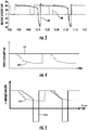
- FIG. 2 illustrates a graph of an exemplary power consumption of heat pump system 10 cycling between a normal operating mode and the free defrost mode (line 104) compared to cycling between the normal operating mode and a standard defrost mode (line 102) where refrigerant circuit 12 is operated in a reverse cycle.
- FIG. 3 illustrates a graph of an exemplary heating capacity of the heat pump system 10 cycling between the normal operating mode and the free defrost mode (line 106) compared to cycling between the normal operating mode and the standard defrost mode (line 108).
- the "positive defrost" method reduces or prevents frosting by reducing the capacity of heat pump system 10 in consideration of the expected reduced heat load requirements of space 40, and utilizes outdoor ambient air for defrosting. However, although capacity is reduced, the method still provides some degree of capacity. As such, system 10 reduces the speed of compressor(s) 20 and/or shuts off some compressors 20, while still providing adequate heating capacity for heat transfer loop 14.
- heat pump system 10 is monitored for frost creation.
- sensor 50 may be operatively associated with evaporator 28 to detect the creation of frost on the coils or other components of evaporator 28.
- Sensor 50 may be a temperature sensor that senses the refrigerant temperature and/or the ambient air temperature.
- system 10 may use any suitable method to detect frost creation on evaporator 28, as described herein.
- controller 100 When the ambient air temperature is above the freezing point of water (i.e., > 0 °C at sea-level) and a predetermined small level of frost is detected on evaporator 28, controller 100 reduces the speed of variable speed compressors 20 and/or reduces the number of operating compressors 20 (in a multi-compressor system). The coil temperature of evaporator 28 is then monitored to determine if the refrigerant temperature increases and exceeds 0 °C (or another predetermined value) after reducing compressor speed and/or the number of operating compressors.
- controller 100 maintains the compressor conditions and the coil temperature is monitored to determine when the refrigerant temperature is stabilized above 0 °C. In this operation, the resulting warmer evaporator coil may be enough to melt the small frost layer present while still providing some heating capacity to heat transfer loop 14.
- compressor(s) 20 are returned to normal operation (i.e., running at normal speed and/or all compressors turned on) and the defrost cycle is terminated when a predetermined temperature of the refrigerant is reached at an appropriate point in the heat exchanger coil.
- sensor 50 may include a coil temperature sensor to detect increased coil temperature and signal controller 100 to terminate the defrost cycle.
- a pressure sensor or pressure switch can be used, or the defrost cycles may be run for a fixed duration of time. However, the free defrost cycle may be terminated when other conditions occur, such as when the differential air-side pressure drop across the evaporator coil returns below a predetermined level.
- system 10 may be switched to free defrost mode, and compressors 20 are turned off and fan 48 is operated to heat the evaporator coil with outdoor ambient air (if above the freezing point of water).
- FIG. 4 illustrates a graph of an exemplary power consumption of heat pump system 10 cycling between a normal operating mode and the positive defrost mode (line 110) compared to cycling between a normal operating mode and a standard defrost mode (line 112) where refrigerant circuit 12 is operated in a reverse cycle.
- FIG. 5 illustrates a graph of an exemplary heating capacity of the heat pump system 10 cycling between the normal operating mode and the positive defrost mode (line 114) compared to cycling between the normal operating mode and the standard defrost mode (line 116).
- System 10 may use various configurations of compressors 20.
- a first configuration includes a fixed speed single compressor
- a second configuration includes a variable speed single compressor
- a third configuration includes multiple fixed speed compressors
- a fourth configuration includes fixed and variable speed compressors.
- System 10 may be operated in the free defrost mode for all four configurations, and system 10 may be operated in the positive defrost mode for the second, third, and fourth configurations.
- the heat pump system may be defrosted in a free defrost mode, a positive defrost mode, or a free and positive defrost mode, without operating the heat pump system in a reverse cycle.
- the free defrost mode includes powering off refrigerant cycle compressors and operating fans to force ambient air over a frosted evaporator for defrosting.
- the positive defrost mode includes reducing the speed of the compressors and/or powering off some of the total of compressors to raise the refrigerant temperature for evaporator defrosting.
- the free and positive defrost mode includes operating the heat pump system in both free defrost mode and positive defrost mode simultaneously or separately in any order.
- the Coefficient of Performance of the heat pump system may be significantly increased, with little or no impact on integrated heating capacity, and with little or no additional hardware costs.
- the integrated heating capacity of the heat pump system can be enhanced at full load, which improves the cost per delivered heating capacity.
- the system increases the Seasonal Coefficient of Performance (e.g., by 15%).
- the described defrost methods may maintain the stability of the building's air or water loop, increase the reliability of the unit, and reduce laboratory test time.
Landscapes
- Engineering & Computer Science (AREA)
- Physics & Mathematics (AREA)
- Mechanical Engineering (AREA)
- Thermal Sciences (AREA)
- General Engineering & Computer Science (AREA)
- Chemical & Material Sciences (AREA)
- Combustion & Propulsion (AREA)
- Air Conditioning Control Device (AREA)
- Heat-Pump Type And Storage Water Heaters (AREA)
- Defrosting Systems (AREA)
Priority Applications (1)
| Application Number | Priority Date | Filing Date | Title |
|---|---|---|---|
| TR2018/15100T TR201815100T4 (tr) | 2014-11-24 | 2014-11-24 | Serbest ve pozitif buz çözmeye yönelik sistemler ve yöntemler. |
Applications Claiming Priority (1)
| Application Number | Priority Date | Filing Date | Title |
|---|---|---|---|
| PCT/IB2014/002733 WO2016083858A1 (en) | 2014-11-24 | 2014-11-24 | Systems and methods for free and positive defrost |
Publications (2)
| Publication Number | Publication Date |
|---|---|
| EP3224554A1 EP3224554A1 (en) | 2017-10-04 |
| EP3224554B1 true EP3224554B1 (en) | 2018-10-03 |
Family
ID=52440708
Family Applications (1)
| Application Number | Title | Priority Date | Filing Date |
|---|---|---|---|
| EP14833359.4A Active EP3224554B1 (en) | 2014-11-24 | 2014-11-24 | Systems and methods for free and positive defrost |
Country Status (7)
| Country | Link |
|---|---|
| US (1) | US10823482B2 (es) |
| EP (1) | EP3224554B1 (es) |
| CN (1) | CN107076477B (es) |
| ES (1) | ES2692846T3 (es) |
| RU (1) | RU2672995C1 (es) |
| TR (1) | TR201815100T4 (es) |
| WO (1) | WO2016083858A1 (es) |
Families Citing this family (15)
| Publication number | Priority date | Publication date | Assignee | Title |
|---|---|---|---|---|
| EP3109572B1 (en) * | 2015-06-22 | 2019-05-01 | Lg Electronics Inc. | Refrigerator |
| US11493260B1 (en) * | 2018-05-31 | 2022-11-08 | Thermo Fisher Scientific (Asheville) Llc | Freezers and operating methods using adaptive defrost |
| EP3587963A1 (en) * | 2018-06-22 | 2020-01-01 | Danfoss A/S | A method for initiating defrosting of an evaporator |
| CN108759261B (zh) * | 2018-07-18 | 2019-09-27 | 中国人民解放军国防科技大学 | 一种并联预冷器及其除冰方法 |
| CN111174437B (zh) * | 2018-11-13 | 2022-03-04 | 艾欧史密斯(中国)热水器有限公司 | 热泵热水器的控制方法 |
| US11131497B2 (en) * | 2019-06-18 | 2021-09-28 | Honeywell International Inc. | Method and system for controlling the defrost cycle of a vapor compression system for increased energy efficiency |
| CN110762673A (zh) * | 2019-11-06 | 2020-02-07 | 珠海格力电器股份有限公司 | 冷水空调系统及其防冻控制方法、存储介质和计算机设备 |
| US11221173B2 (en) * | 2019-11-13 | 2022-01-11 | Lineage Logistics, LLC | Controlled defrost for chilled environments |
| DE102020107006A1 (de) * | 2020-03-13 | 2021-09-16 | Volkswagen Aktiengesellschaft | Verfahren zum Betreiben einer Wärmepumpe eines Kraftfahrzeuges und Wärmepumpe |
| DE102020112376A1 (de) * | 2020-05-07 | 2021-11-11 | Wolf Gmbh | Wärmepumpen-Anlage |
| US11466910B2 (en) * | 2020-05-11 | 2022-10-11 | Rheem Manufacturing Company | Systems and methods for reducing frost accumulation on heat pump evaporator coils |
| CN111964300B (zh) * | 2020-08-17 | 2021-11-30 | 广东美的暖通设备有限公司 | 空气源热泵设备的控制方法、装置、设备和可读存储介质 |
| US11709004B2 (en) * | 2020-12-16 | 2023-07-25 | Lennox Industries Inc. | Method and a system for preventing a freeze event using refrigerant temperature |
| CN113587530B (zh) * | 2021-08-12 | 2023-04-14 | 澳蓝(福建)实业有限公司 | 一种用于数据中心的间接蒸发换热芯体的除霜方法 |
| CN115574487B (zh) * | 2022-10-08 | 2023-06-23 | 中国建筑西南设计研究院有限公司 | 一种结除霜工况下的空气源热泵供热系统性能评价方法 |
Family Cites Families (33)
| Publication number | Priority date | Publication date | Assignee | Title |
|---|---|---|---|---|
| US4122687A (en) | 1976-12-09 | 1978-10-31 | Mckee Thomas M | Refrigeration system with low energy defrost |
| US4086779A (en) | 1977-01-25 | 1978-05-02 | Lewis Roswell E | Refrigeration defrosting |
| US4295340A (en) | 1979-02-14 | 1981-10-20 | Tyler Refrigeration Corporation | Refrigerated display case having ambient air defrost |
| US4375155A (en) | 1981-12-24 | 1983-03-01 | Emhart Industries, Inc. | Reach-in refrigerated display case with ambient air defrost |
| US4951473A (en) | 1988-10-12 | 1990-08-28 | Honeywell, Inc. | Heat pump defrosting operation |
| US5533357A (en) * | 1995-02-15 | 1996-07-09 | Carrier Corporation | Air conditioning apparatus |
| US5927083A (en) * | 1998-03-09 | 1999-07-27 | Carrier Corporation | Compressor cycle dependent defrost control |
| US6490876B2 (en) * | 2000-02-15 | 2002-12-10 | Whirlpool Corporation | Method and apparatus for de-icing dehumidifier |
| NZ503106A (en) | 2000-02-28 | 2002-07-26 | Fisher & Paykel Appliances Ltd | Refrigerator with at least a fresh food compartment and evaporator operating within 10 degrees centigrade below compartment temperature, so that air at above 0 degrees is blown over evaporator during off cycle |
| US6334321B1 (en) | 2000-03-15 | 2002-01-01 | Carrier Corporation | Method and system for defrost control on reversible heat pumps |
| JP3932913B2 (ja) * | 2002-01-29 | 2007-06-20 | ダイキン工業株式会社 | ヒートポンプ式給湯機 |
| GB2405360B (en) | 2003-08-27 | 2007-02-07 | Ebac Ltd | Dehumidifiers |
| US9068771B2 (en) | 2006-01-20 | 2015-06-30 | Carrier Corporation | Method for automatically adjusting the defrost interval in a heat pump system |
| KR100798781B1 (ko) * | 2006-10-26 | 2008-01-29 | 삼성전자주식회사 | 공기조화기의 운전제어방법 |
| US7836718B2 (en) * | 2007-06-29 | 2010-11-23 | Electrolux Home Products, Inc. | Hot gas defrost method and apparatus |
| US8590326B2 (en) * | 2007-10-09 | 2013-11-26 | Panasonic Corporation | Refrigeration cycle apparatus |
| CN102865702A (zh) * | 2008-06-27 | 2013-01-09 | 开利公司 | 热气除霜工艺 |
| CN101782305B (zh) * | 2009-01-15 | 2013-03-06 | 珠海格力电器股份有限公司 | 热泵型空气调节装置及其除霜方法 |
| JP5200996B2 (ja) * | 2009-02-24 | 2013-06-05 | ダイキン工業株式会社 | ヒートポンプシステム |
| CN102648384B (zh) | 2009-11-25 | 2014-06-18 | 大金工业株式会社 | 集装箱用制冷装置 |
| JP2012048700A (ja) * | 2010-07-29 | 2012-03-08 | Sony Corp | 情報処理装置 |
| JP2012057869A (ja) | 2010-09-09 | 2012-03-22 | Panasonic Corp | 空気調和機 |
| KR20120092442A (ko) | 2011-02-11 | 2012-08-21 | 삼성전자주식회사 | 냉장고 |
| US8528946B2 (en) * | 2011-06-28 | 2013-09-10 | I-Tek Metal Mfg. Co., Ltd. | Door lock with idle travel in a locking state |
| US9970696B2 (en) | 2011-07-20 | 2018-05-15 | Thermo King Corporation | Defrost for transcritical vapor compression system |
| WO2013037106A1 (zh) | 2011-09-14 | 2013-03-21 | 合肥美的荣事达电冰箱有限公司 | 化霜冰箱及化霜冰箱的控制方法 |
| JP5836083B2 (ja) * | 2011-11-24 | 2015-12-24 | 三菱重工業株式会社 | ヒートポンプシステムの除霜運転方法及びヒートポンプシステム |
| JP2014013122A (ja) * | 2012-07-05 | 2014-01-23 | Panasonic Corp | 冷凍サイクル装置およびそれを備えた温水生成装置 |
| KR101953120B1 (ko) | 2012-08-27 | 2019-03-04 | 삼성전자주식회사 | 냉장고 및 그 제어방법 |
| US8997507B2 (en) | 2012-10-22 | 2015-04-07 | Whirlpool Corporation | Low energy evaporator defrost |
| US9175888B2 (en) | 2012-12-03 | 2015-11-03 | Whirlpool Corporation | Low energy refrigerator heat source |
| KR101982776B1 (ko) | 2012-12-10 | 2019-05-27 | 엘지전자 주식회사 | 냉장고 및 그 동작방법 |
| SE537022C2 (sv) * | 2012-12-21 | 2014-12-09 | Fläkt Woods AB | Förfarande och anordning för avfrostning av en förångare vidett luftbehandlingsaggregat |
-
2014
- 2014-11-24 TR TR2018/15100T patent/TR201815100T4/tr unknown
- 2014-11-24 US US15/528,681 patent/US10823482B2/en active Active
- 2014-11-24 CN CN201480083611.5A patent/CN107076477B/zh active Active
- 2014-11-24 RU RU2017117893A patent/RU2672995C1/ru active
- 2014-11-24 ES ES14833359.4T patent/ES2692846T3/es active Active
- 2014-11-24 WO PCT/IB2014/002733 patent/WO2016083858A1/en active Application Filing
- 2014-11-24 EP EP14833359.4A patent/EP3224554B1/en active Active
Non-Patent Citations (1)
| Title |
|---|
| None * |
Also Published As
| Publication number | Publication date |
|---|---|
| CN107076477B (zh) | 2021-04-27 |
| ES2692846T3 (es) | 2018-12-05 |
| EP3224554A1 (en) | 2017-10-04 |
| US10823482B2 (en) | 2020-11-03 |
| TR201815100T4 (tr) | 2018-11-21 |
| US20170276422A1 (en) | 2017-09-28 |
| WO2016083858A1 (en) | 2016-06-02 |
| CN107076477A (zh) | 2017-08-18 |
| RU2672995C1 (ru) | 2018-11-21 |
Similar Documents
| Publication | Publication Date | Title |
|---|---|---|
| EP3224554B1 (en) | Systems and methods for free and positive defrost | |
| EP2936008B1 (en) | Method for defrosting of an evaporator in connection with an air handling unit | |
| EP3500805B1 (en) | Systems and methods for controlling a refrigeration system | |
| USRE29966E (en) | Heat pump with frost-free outdoor coil | |
| EP2833075B1 (en) | Air conditioner and control method thereof | |
| EP3699514B1 (en) | Systems and methods for controlling a refrigeration system | |
| EP0505315B1 (en) | Defrost control | |
| EP2102570B1 (en) | Methods and systems for controlling air conditioning systems having a cooling mode and a free-cooling mode | |
| EP2940407B1 (en) | Heat pump hot water heater | |
| EP2592367A2 (en) | Refrigeration cycle apparatus and hot water producing apparatus | |
| EP2837901B1 (en) | Cooling system | |
| US9797611B2 (en) | Combination air and ground source heating and/or cooling system | |
| EP1630497B1 (en) | Cooling plant for a fluid with control of variables | |
| CN107076476B (zh) | 带独立除霜的可变制冷剂hvac系统 | |
| US11761698B2 (en) | Defrost cycle control assembly in a heat pump | |
| CN201047687Y (zh) | 热气旁通回气补热除霜恒温热水系统 | |
| EP3344932B1 (en) | A heat pump system | |
| JP6367642B2 (ja) | 空気調和機 | |
| WO2021044886A1 (ja) | 冷凍サイクル装置 | |
| JP2006226567A (ja) | 空気調和機 |
Legal Events
| Date | Code | Title | Description |
|---|---|---|---|
| PUAI | Public reference made under article 153(3) epc to a published international application that has entered the european phase |
Free format text: ORIGINAL CODE: 0009012 |
|
| 17P | Request for examination filed |
Effective date: 20170512 |
|
| AK | Designated contracting states |
Kind code of ref document: A1 Designated state(s): AL AT BE BG CH CY CZ DE DK EE ES FI FR GB GR HR HU IE IS IT LI LT LU LV MC MK MT NL NO PL PT RO RS SE SI SK SM TR |
|
| AX | Request for extension of the european patent |
Extension state: BA ME |
|
| DAX | Request for extension of the european patent (deleted) | ||
| REG | Reference to a national code |
Ref country code: DE Ref legal event code: R079 Ref document number: 602014033521 Country of ref document: DE Free format text: PREVIOUS MAIN CLASS: F25B0047020000 Ipc: F25B0030020000 |
|
| RIC1 | Information provided on ipc code assigned before grant |
Ipc: F25D 21/02 20060101ALI20180321BHEP Ipc: F25B 47/02 20060101ALI20180321BHEP Ipc: F25D 21/04 20060101ALI20180321BHEP Ipc: F25B 30/02 20060101AFI20180321BHEP Ipc: F25B 49/02 20060101ALI20180321BHEP Ipc: F25B 1/10 20060101ALI20180321BHEP |
|
| GRAP | Despatch of communication of intention to grant a patent |
Free format text: ORIGINAL CODE: EPIDOSNIGR1 |
|
| INTG | Intention to grant announced |
Effective date: 20180508 |
|
| GRAS | Grant fee paid |
Free format text: ORIGINAL CODE: EPIDOSNIGR3 |
|
| GRAA | (expected) grant |
Free format text: ORIGINAL CODE: 0009210 |
|
| AK | Designated contracting states |
Kind code of ref document: B1 Designated state(s): AL AT BE BG CH CY CZ DE DK EE ES FI FR GB GR HR HU IE IS IT LI LT LU LV MC MK MT NL NO PL PT RO RS SE SI SK SM TR |
|
| REG | Reference to a national code |
Ref country code: GB Ref legal event code: FG4D |
|
| REG | Reference to a national code |
Ref country code: CH Ref legal event code: EP Ref country code: AT Ref legal event code: REF Ref document number: 1049038 Country of ref document: AT Kind code of ref document: T Effective date: 20181015 |
|
| REG | Reference to a national code |
Ref country code: IE Ref legal event code: FG4D Ref country code: DE Ref legal event code: R096 Ref document number: 602014033521 Country of ref document: DE |
|
| REG | Reference to a national code |
Ref country code: NL Ref legal event code: FP |
|
| REG | Reference to a national code |
Ref country code: ES Ref legal event code: FG2A Ref document number: 2692846 Country of ref document: ES Kind code of ref document: T3 Effective date: 20181205 |
|
| REG | Reference to a national code |
Ref country code: LT Ref legal event code: MG4D |
|
| REG | Reference to a national code |
Ref country code: AT Ref legal event code: MK05 Ref document number: 1049038 Country of ref document: AT Kind code of ref document: T Effective date: 20181003 |
|
| PG25 | Lapsed in a contracting state [announced via postgrant information from national office to epo] |
Ref country code: IS Free format text: LAPSE BECAUSE OF FAILURE TO SUBMIT A TRANSLATION OF THE DESCRIPTION OR TO PAY THE FEE WITHIN THE PRESCRIBED TIME-LIMIT Effective date: 20190203 Ref country code: FI Free format text: LAPSE BECAUSE OF FAILURE TO SUBMIT A TRANSLATION OF THE DESCRIPTION OR TO PAY THE FEE WITHIN THE PRESCRIBED TIME-LIMIT Effective date: 20181003 Ref country code: BG Free format text: LAPSE BECAUSE OF FAILURE TO SUBMIT A TRANSLATION OF THE DESCRIPTION OR TO PAY THE FEE WITHIN THE PRESCRIBED TIME-LIMIT Effective date: 20190103 Ref country code: LV Free format text: LAPSE BECAUSE OF FAILURE TO SUBMIT A TRANSLATION OF THE DESCRIPTION OR TO PAY THE FEE WITHIN THE PRESCRIBED TIME-LIMIT Effective date: 20181003 Ref country code: HR Free format text: LAPSE BECAUSE OF FAILURE TO SUBMIT A TRANSLATION OF THE DESCRIPTION OR TO PAY THE FEE WITHIN THE PRESCRIBED TIME-LIMIT Effective date: 20181003 Ref country code: AT Free format text: LAPSE BECAUSE OF FAILURE TO SUBMIT A TRANSLATION OF THE DESCRIPTION OR TO PAY THE FEE WITHIN THE PRESCRIBED TIME-LIMIT Effective date: 20181003 Ref country code: PL Free format text: LAPSE BECAUSE OF FAILURE TO SUBMIT A TRANSLATION OF THE DESCRIPTION OR TO PAY THE FEE WITHIN THE PRESCRIBED TIME-LIMIT Effective date: 20181003 Ref country code: LT Free format text: LAPSE BECAUSE OF FAILURE TO SUBMIT A TRANSLATION OF THE DESCRIPTION OR TO PAY THE FEE WITHIN THE PRESCRIBED TIME-LIMIT Effective date: 20181003 Ref country code: NO Free format text: LAPSE BECAUSE OF FAILURE TO SUBMIT A TRANSLATION OF THE DESCRIPTION OR TO PAY THE FEE WITHIN THE PRESCRIBED TIME-LIMIT Effective date: 20190103 Ref country code: CZ Free format text: LAPSE BECAUSE OF FAILURE TO SUBMIT A TRANSLATION OF THE DESCRIPTION OR TO PAY THE FEE WITHIN THE PRESCRIBED TIME-LIMIT Effective date: 20181003 |
|
| PG25 | Lapsed in a contracting state [announced via postgrant information from national office to epo] |
Ref country code: PT Free format text: LAPSE BECAUSE OF FAILURE TO SUBMIT A TRANSLATION OF THE DESCRIPTION OR TO PAY THE FEE WITHIN THE PRESCRIBED TIME-LIMIT Effective date: 20190203 Ref country code: GR Free format text: LAPSE BECAUSE OF FAILURE TO SUBMIT A TRANSLATION OF THE DESCRIPTION OR TO PAY THE FEE WITHIN THE PRESCRIBED TIME-LIMIT Effective date: 20190104 Ref country code: RS Free format text: LAPSE BECAUSE OF FAILURE TO SUBMIT A TRANSLATION OF THE DESCRIPTION OR TO PAY THE FEE WITHIN THE PRESCRIBED TIME-LIMIT Effective date: 20181003 Ref country code: SE Free format text: LAPSE BECAUSE OF FAILURE TO SUBMIT A TRANSLATION OF THE DESCRIPTION OR TO PAY THE FEE WITHIN THE PRESCRIBED TIME-LIMIT Effective date: 20181003 Ref country code: AL Free format text: LAPSE BECAUSE OF FAILURE TO SUBMIT A TRANSLATION OF THE DESCRIPTION OR TO PAY THE FEE WITHIN THE PRESCRIBED TIME-LIMIT Effective date: 20181003 |
|
| REG | Reference to a national code |
Ref country code: CH Ref legal event code: PL |
|
| REG | Reference to a national code |
Ref country code: DE Ref legal event code: R097 Ref document number: 602014033521 Country of ref document: DE |
|
| PG25 | Lapsed in a contracting state [announced via postgrant information from national office to epo] |
Ref country code: IT Free format text: LAPSE BECAUSE OF FAILURE TO SUBMIT A TRANSLATION OF THE DESCRIPTION OR TO PAY THE FEE WITHIN THE PRESCRIBED TIME-LIMIT Effective date: 20181003 Ref country code: LU Free format text: LAPSE BECAUSE OF NON-PAYMENT OF DUE FEES Effective date: 20181124 Ref country code: DK Free format text: LAPSE BECAUSE OF FAILURE TO SUBMIT A TRANSLATION OF THE DESCRIPTION OR TO PAY THE FEE WITHIN THE PRESCRIBED TIME-LIMIT Effective date: 20181003 |
|
| PLBE | No opposition filed within time limit |
Free format text: ORIGINAL CODE: 0009261 |
|
| STAA | Information on the status of an ep patent application or granted ep patent |
Free format text: STATUS: NO OPPOSITION FILED WITHIN TIME LIMIT |
|
| REG | Reference to a national code |
Ref country code: BE Ref legal event code: MM Effective date: 20181130 |
|
| REG | Reference to a national code |
Ref country code: IE Ref legal event code: MM4A |
|
| PG25 | Lapsed in a contracting state [announced via postgrant information from national office to epo] |
Ref country code: MC Free format text: LAPSE BECAUSE OF FAILURE TO SUBMIT A TRANSLATION OF THE DESCRIPTION OR TO PAY THE FEE WITHIN THE PRESCRIBED TIME-LIMIT Effective date: 20181003 Ref country code: EE Free format text: LAPSE BECAUSE OF FAILURE TO SUBMIT A TRANSLATION OF THE DESCRIPTION OR TO PAY THE FEE WITHIN THE PRESCRIBED TIME-LIMIT Effective date: 20181003 Ref country code: SM Free format text: LAPSE BECAUSE OF FAILURE TO SUBMIT A TRANSLATION OF THE DESCRIPTION OR TO PAY THE FEE WITHIN THE PRESCRIBED TIME-LIMIT Effective date: 20181003 Ref country code: RO Free format text: LAPSE BECAUSE OF FAILURE TO SUBMIT A TRANSLATION OF THE DESCRIPTION OR TO PAY THE FEE WITHIN THE PRESCRIBED TIME-LIMIT Effective date: 20181003 Ref country code: CH Free format text: LAPSE BECAUSE OF NON-PAYMENT OF DUE FEES Effective date: 20181130 Ref country code: SK Free format text: LAPSE BECAUSE OF FAILURE TO SUBMIT A TRANSLATION OF THE DESCRIPTION OR TO PAY THE FEE WITHIN THE PRESCRIBED TIME-LIMIT Effective date: 20181003 Ref country code: LI Free format text: LAPSE BECAUSE OF NON-PAYMENT OF DUE FEES Effective date: 20181130 |
|
| 26N | No opposition filed |
Effective date: 20190704 |
|
| PG25 | Lapsed in a contracting state [announced via postgrant information from national office to epo] |
Ref country code: IE Free format text: LAPSE BECAUSE OF NON-PAYMENT OF DUE FEES Effective date: 20181124 Ref country code: SI Free format text: LAPSE BECAUSE OF FAILURE TO SUBMIT A TRANSLATION OF THE DESCRIPTION OR TO PAY THE FEE WITHIN THE PRESCRIBED TIME-LIMIT Effective date: 20181003 |
|
| PG25 | Lapsed in a contracting state [announced via postgrant information from national office to epo] |
Ref country code: BE Free format text: LAPSE BECAUSE OF NON-PAYMENT OF DUE FEES Effective date: 20181130 |
|
| PG25 | Lapsed in a contracting state [announced via postgrant information from national office to epo] |
Ref country code: MT Free format text: LAPSE BECAUSE OF NON-PAYMENT OF DUE FEES Effective date: 20181124 |
|
| PG25 | Lapsed in a contracting state [announced via postgrant information from national office to epo] |
Ref country code: HU Free format text: LAPSE BECAUSE OF FAILURE TO SUBMIT A TRANSLATION OF THE DESCRIPTION OR TO PAY THE FEE WITHIN THE PRESCRIBED TIME-LIMIT; INVALID AB INITIO Effective date: 20141124 Ref country code: CY Free format text: LAPSE BECAUSE OF FAILURE TO SUBMIT A TRANSLATION OF THE DESCRIPTION OR TO PAY THE FEE WITHIN THE PRESCRIBED TIME-LIMIT Effective date: 20181003 Ref country code: MK Free format text: LAPSE BECAUSE OF NON-PAYMENT OF DUE FEES Effective date: 20181003 |
|
| P01 | Opt-out of the competence of the unified patent court (upc) registered |
Effective date: 20230527 |
|
| PGFP | Annual fee paid to national office [announced via postgrant information from national office to epo] |
Ref country code: NL Payment date: 20231020 Year of fee payment: 10 |
|
| PGFP | Annual fee paid to national office [announced via postgrant information from national office to epo] |
Ref country code: GB Payment date: 20231019 Year of fee payment: 10 |
|
| PGFP | Annual fee paid to national office [announced via postgrant information from national office to epo] |
Ref country code: ES Payment date: 20231201 Year of fee payment: 10 |
|
| PGFP | Annual fee paid to national office [announced via postgrant information from national office to epo] |
Ref country code: TR Payment date: 20231024 Year of fee payment: 10 Ref country code: FR Payment date: 20231020 Year of fee payment: 10 Ref country code: DE Payment date: 20231019 Year of fee payment: 10 |