EP3224502B1 - Zweiteiliger kolbenring - Google Patents
Zweiteiliger kolbenring Download PDFInfo
- Publication number
- EP3224502B1 EP3224502B1 EP15763331.4A EP15763331A EP3224502B1 EP 3224502 B1 EP3224502 B1 EP 3224502B1 EP 15763331 A EP15763331 A EP 15763331A EP 3224502 B1 EP3224502 B1 EP 3224502B1
- Authority
- EP
- European Patent Office
- Prior art keywords
- section
- ring
- piston ring
- base body
- shaped cross
- Prior art date
- Legal status (The legal status is an assumption and is not a legal conclusion. Google has not performed a legal analysis and makes no representation as to the accuracy of the status listed.)
- Not-in-force
Links
- 230000006835 compression Effects 0.000 claims description 10
- 238000007906 compression Methods 0.000 claims description 10
- 238000005452 bending Methods 0.000 description 6
- 238000002485 combustion reaction Methods 0.000 description 4
- 239000000463 material Substances 0.000 description 3
- 238000004519 manufacturing process Methods 0.000 description 2
- 239000011343 solid material Substances 0.000 description 2
- 229920001817 Agar Polymers 0.000 description 1
- 238000010276 construction Methods 0.000 description 1
- 238000010790 dilution Methods 0.000 description 1
- 239000012895 dilution Substances 0.000 description 1
- 230000000694 effects Effects 0.000 description 1
- 238000000034 method Methods 0.000 description 1
- 238000004080 punching Methods 0.000 description 1
- 238000007789 sealing Methods 0.000 description 1
- 239000007787 solid Substances 0.000 description 1
- 230000008093 supporting effect Effects 0.000 description 1
- 230000007704 transition Effects 0.000 description 1
Images

Classifications
-
- F—MECHANICAL ENGINEERING; LIGHTING; HEATING; WEAPONS; BLASTING
- F16—ENGINEERING ELEMENTS AND UNITS; GENERAL MEASURES FOR PRODUCING AND MAINTAINING EFFECTIVE FUNCTIONING OF MACHINES OR INSTALLATIONS; THERMAL INSULATION IN GENERAL
- F16J—PISTONS; CYLINDERS; SEALINGS
- F16J9/00—Piston-rings, e.g. non-metallic piston-rings, seats therefor; Ring sealings of similar construction
- F16J9/06—Piston-rings, e.g. non-metallic piston-rings, seats therefor; Ring sealings of similar construction using separate springs or elastic elements expanding the rings; Springs therefor ; Expansion by wedging
- F16J9/061—Piston-rings, e.g. non-metallic piston-rings, seats therefor; Ring sealings of similar construction using separate springs or elastic elements expanding the rings; Springs therefor ; Expansion by wedging using metallic coiled or blade springs
-
- F—MECHANICAL ENGINEERING; LIGHTING; HEATING; WEAPONS; BLASTING
- F16—ENGINEERING ELEMENTS AND UNITS; GENERAL MEASURES FOR PRODUCING AND MAINTAINING EFFECTIVE FUNCTIONING OF MACHINES OR INSTALLATIONS; THERMAL INSULATION IN GENERAL
- F16J—PISTONS; CYLINDERS; SEALINGS
- F16J9/00—Piston-rings, e.g. non-metallic piston-rings, seats therefor; Ring sealings of similar construction
- F16J9/06—Piston-rings, e.g. non-metallic piston-rings, seats therefor; Ring sealings of similar construction using separate springs or elastic elements expanding the rings; Springs therefor ; Expansion by wedging
-
- F—MECHANICAL ENGINEERING; LIGHTING; HEATING; WEAPONS; BLASTING
- F16—ENGINEERING ELEMENTS AND UNITS; GENERAL MEASURES FOR PRODUCING AND MAINTAINING EFFECTIVE FUNCTIONING OF MACHINES OR INSTALLATIONS; THERMAL INSULATION IN GENERAL
- F16J—PISTONS; CYLINDERS; SEALINGS
- F16J9/00—Piston-rings, e.g. non-metallic piston-rings, seats therefor; Ring sealings of similar construction
- F16J9/06—Piston-rings, e.g. non-metallic piston-rings, seats therefor; Ring sealings of similar construction using separate springs or elastic elements expanding the rings; Springs therefor ; Expansion by wedging
- F16J9/064—Rings with a flat annular side rail
- F16J9/066—Spring expander from sheet metal
- F16J9/068—Spring expander from sheet metal corrugated in the axial direction
Definitions
- the invention relates to an improved piston ring, in particular compression ring, with a two-part construction.
- piston rings are therefore also referred to as compression or top rings.
- the amount of gas that can pass through the top ring ultimately determines the amount of gas that can pass through the engine as a so-called blow-by. It is important here to keep the compression of the engine as high as possible by optimizing the seal in order to optimize its efficiency. By reducing blow-by losses, the resulting oil dilution can be minimized. Basically, it is desirable to avoid blow-by losses as much as possible.
- Rectangular or trapezoidal rings are predominantly used in the uppermost piston ring groove. These rings gain their contact pressure on the cylinder surface from the bias of their body. By an appropriate thickness of material to ensure this voltage, the ring can follow irregularities in the cylinder bore surface worse.
- lower material thickness piston rings can better follow irregularities, they also have lower stress and, due to the reduced thickness, are more prone to ring fractures than thicker rings.
- the latter applies in particular to compression rings with a substantially U-shaped cross-section, since here relatively thin legs are present, on the one hand bear against the groove flank and on the other hand are exposed to the combustion pressure during the power stroke. These loads can create a bending moment that can lead to breakage.
- the object is also to improve the ⁇ labstreif Koch, with at most the same or even reduced friction losses. It is proposed a piston ring, in particular compression ring, with improved mold filling capacity (higher elasticity in the radial direction).
- the task is achieved, inter alia, by removing material inside the ring in relation to a solid material ring. Since the tread and flanks or their respective surfaces are still needed, this leads to a U-shaped cross-section.
- the ring becomes more flexible in the radial direction.
- the U-shaped cross-section in turn reduces the necessary tangential force and weakens the upper heavily loaded flank. Due to the reduced rigidity, the radial pressure, which results from the ring geometry, is reduced with the same dimensions.
- the piston ring according to the invention can follow more pronounced cylinder distortions better and ensure a better seal on the running surface. Since the wall thickness or the adjacent surface remains unchanged at the two ring flanks, the seal on the flanks is still given.
- a comparable mold filling capacity would be possible with conventional solid material rings only by enormous Tangentialkrafterhöhung, which in turn would lead to high friction losses.
- a meandering spring in the proposed ring Due to the high pressure on the ring flanks and the contact points with the groove flanks at the outer points of the piston ring can cause a bending moment in the engine operation, which is intercepted by a meandering spring in the proposed ring, whose height in the interior of the U-shaped body or axially between the legs thereof prevents bending of the thinner leg sections.
- the meander-shaped spring thus supports the limbs of the U-shaped main body with respect to loads in the axial direction.
- the base body and / or the interior of the U-shaped cross section have a rectangular shape.
- already known manufacturing methods for the piston ring are applicable.
- new methods such as punching and bending can be used.
- FIG. 1 shows a cross section through a conventional one-piece compression piston ring with a base body 2 with a U-shaped cross-section.
- the lower edge 3 of the ring abuts against the annular groove (not shown).
- the combustion pressure at the power stroke of the engine indicated by arrows.
- the flank due to the U-profile, has a substantially smaller wall thickness than, for example, rectangular rings, bending of the flank can occur, as shown here. High peak load and / or fatigue due to continual flexing during operation may eventually result in breakage of the ring, such as in the area of transition into the legs of the U-profile.
- the one-piece U-shaped piston ring shown has a lower radial pressure compared to a rectangular ring with otherwise the same dimensions. The contact pressure on the cylinder surface is therefore lower.
- FIG. 2 shows an embodiment of such a piston ring.
- the piston ring 1 has a base body 2 with a U-shaped cross-section.
- the radially inwardly facing edges of the legs of the U-section are chamfered.
- rectangular as well as rounded edges or combinations thereof are possible.
- a meandering annular spring 4 is added inside the U-profile.
- the meander loops 5 are alternately at the upper and lower inner edge of the U-profile.
- the meander loops 6 are alternately on the radially inwardly facing edges of the legs 3 of the U-shaped cross-section.
- the two-part piston ring has two advantageous properties over a one-piece U-shaped ring.
- the radial pressure is increased by the annular spring 4, which can push the main body 2 by the abutment against the radially inner edges of the legs to the outside.
- the inner portions of the annular spring 4 support the legs or flanks 3 against compressive loads in the axial direction. Ring breaking can thus be avoided.
- the slots are located, for example, in the respective outer third in relation to the height.
- the annular spring 4 is in one piece. Other divisions are also possible, as long as a sufficiently large area in the middle remains in one piece to ensure the stability of the spring.
- a symmetrical spring which also has meander loops separated by slots in the inner region. This may be desirable for reasons of simplified manufacture of the spring, even if the inner loops on the edge are then inoperative.
- the piston ring can also be used preferably as a compression or top ring.
- the combustion pressure can penetrate at the open points relatively unhindered to the inner base surface of the body and thus press the piston ring to the cylinder surface. This is an advantage over more massive elements of two-piece piston rings where such gas passage is not possible.
- FIG. 3 shows an alternative embodiment of the piston ring in cross section.
- an asymmetrical annular spring 4 is used, which has exclusively a (wider) inner area with meandering loops 5 and a (narrower) outer area with meandering loops 6.
- the respective lower meander loops abut against the lower leg of the U-profile. Shown dashed are the circumferentially underlying loops, which then rest against the upper leg.
- FIGS. 4 and 5 show alternatives for the meander shape of the ring spring.
- FIG. 4 are (solid) trapezoidal loops and rectangular loops (dashed) shown.
- FIG. 4 it is true that in the case of wavy Ma sourceverierin only point or line-shaped contact points are replaced at the U-profile by areal plants. This can be advantageous to initiate the forces distributed evenly.
- the piston ring can be better stiffened in the axial direction against bending moments by steeper to vertical gradients of the spring.
- FIG. 5 shows a wavy meandering course. This can also be adjusted by adjusting the slope and / or number of loops with respect to the supporting effect.
Landscapes
- Engineering & Computer Science (AREA)
- General Engineering & Computer Science (AREA)
- Mechanical Engineering (AREA)
- Pistons, Piston Rings, And Cylinders (AREA)
Description
- Die Erfindung betrifft einen verbesserten Kolbenring, insbesondere Kompressionsring, mit einem zweiteiligen Aufbau.
- Eine der Aufgaben von Kolbenringen ist die Abdichtung der Brennkammer gegenüber dem Kurbelwellengehäuse. Solche Ringe werden daher auch als Kompressions- bzw. Top-Ringe bezeichnet. Die Gasmenge, die den obersten Ring passieren kann, bestimmt letztlich die Menge an Gas, die als so genanntes Blow-By durch den Motor nach außen gelangen kann. Es gilt hierbei, durch eine möglichst gute Abdichtung die Kompression des Motors so hoch wie möglich zu halten, um dessen Effizienz zu optimieren. Durch die Verringerung von Blow-By-Verlusten kann auch die davon verursachte Ölverdünnung minimiert werden. Grundsätzlich ist es erwünscht, Blow-By-Verluste soweit wie möglich zu vermeiden.
- Dies ist allerdings nur durch eine möglichst gute Abdichtung zwischen Zylinderwand bzw. Laufbuchse und Kolben möglich. In der Praxis steht dem jedoch gegenüber, dass gleichzeitig eine möglichst geringe Reibung zwischen Kolbenringen und Zylinderinnenseite zu erzielen ist. Der Anpressdruck der Kolbenringe an die Zylinderlauffläche kann daher nicht unbegrenzt erhöht werden, da ansonsten die Reibung zu hoch würde. Der Kolbenring muss sowohl an der Ringflanke als auch an der Zylinderlauffläche dichtend wirken.
- In der obersten Kolbenringnut werden überwiegend Rechteck- oder Trapezringe verwendet. Diese Ringe gewinnen ihren Anpressdruck an die Zylinderlauffläche aus der Vorspannung ihres Grundkörpers. Durch eine entsprechende Materialstärke, um diese Spannung zu gewährleisten, kann der Ring jedoch Unregelmäßigkeiten in der Zylinderlauffläche schlechter folgen.
- Kolbenringe mit geringerer Materialstärke können zwar Unregelmäßigkeiten besser folgen, weisen aber auch eine geringere Spannung auf und neigen aufgrund der verringerten Dicken eher zu Ringbrüchen als dickere Ringe. Letzteres gilt insbesondere für Kompressionsringe mit im Wesentlichen U-förmigem Querschnitt, da hier relativ dünne Schenkel vorhanden sind, die einerseits an der Nutflanke anliegen und andererseits dem Verbrennungsdruck beim Arbeitstakt ausgesetzt sind. Diese Belastungen können ein Biegemoment entfalten, das zu einem Bruch führen kann.
- Demzufolge ist es Aufgabe der vorliegenden Erfindung, einen zweiteiligen Kolbenring mit verringertem Ölverbrauch und zumindest gleicher Widerstandsfähigkeit gegenüber Belastungen bereitzustellen, die zum Ringbrechen führen können. Die Aufgabe besteht ferner auch darin, die Ölabstreifwirkung zu verbessern, bei höchstens gleichen oder sogar verringerten Reibverlusten. Es wird ein Kolbenring, insbesondere Kompressionsring, mit verbessertem Formfüllvermögen (höherer Elastizität in Radialrichtung) vorgeschlagen.
- Gemäß einem Aspekt der Erfindung wird ein Kolbenring, insbesondere Kompressionsring, bereitgestellt, umfassend:
- einen an einer Stoßstelle offenen ringförmigen Grundkörper mit einem U-förmigem Querschnitt, dessen offene Seite in Radialrichtung nach innen weist;
- eine in der Axialrichtung mäanderförmig verlaufende Ringfeder, die den Grundkörper in Radialrichtung nach außen vorspannt;
- Die Aufgabe wird unter anderem durch Entfernen von Material im Ringinneren gegenüber einem Vollmaterial-Ring erreicht. Da die Lauffläche und Flanken bzw. deren jeweilige Flächen weiterhin benötigt werden, führt dies zu einem U-förmigen Querschnitt. Durch das Verwenden eines U-förmigen Grundkörpers wird der Ring in radialer Richtung flexibler. Der U-förmige Querschnitt reduziert wiederum die notwendige Tangentialkraft und schwächt die obere stark druckbelastete Flanke. Durch die reduzierte Steifigkeit wird auch der Radialdruck, der aus der Ringgeometrie entsteht, bei gleichen Abmaßen reduziert. Diese Nachteile werden durch die vorgeschlagene Verwendung einer Feder kompensiert.
- Bei gleicher Tangentialkraft und höherem Formfüllvermögen kann der erfindungsgemäße Kolbenring ausgeprägteren Zylinderverzügen besser folgen und eine höhere Dichtigkeit an der Lauffläche gewährleisten. Da die Wandstärke bzw. die anliegende Fläche an den beiden Ringflanken unverändert bleibt, ist die Abdichtung an den Flanken weiterhin gegeben. Ein vergleichbares Formfüllvermögen wäre mit konventionellen Vollmaterialringen nur durch enorme Tangentialkrafterhöhung möglich, was wiederum zu hohen Reibverlusten führen würde.
- Durch den hohen Druck auf die Ringflanken und die Kontaktpunkte mit den Nutflanken an den äußeren Punkten des Kolbenring kann im Motorbetrieb ein Biegemoment entstehen, das durch bei dem vorgeschlagenen Ring durch eine mäanderförmige Feder abgefangen wird, deren Höhe im Inneren des U-förmigen Grundkörpers bzw. axial zwischen den Schenkeln davon ein Verbiegen der dünneren Schenkelabschnitte verhindert. Die mäanderförmige Feder stützt die Schenkel des U-förmigen Grundkörpers gegenüber Belastungen in Axialrichtung somit ab.
- Insgesamt entsteht somit ein Kolbenring mit verringertem Ölverbrauch / verbesserter Ölabstreifwirkung bei höchstens gleichen oder sogar verringerten Reibverlusten bei gleichzeitig gegebener Stabilität gegenüber Ringbrechen.
- Gemäß einer Ausführungsform weisen der Grundkörper und/oder das Innere des U-förmigen Querschnitts eine rechteckige Form auf. Dadurch sind bereits bekannte Herstellungsverfahren für den Kolbenring anwendbar. Alternativ können jedoch auch neue Verfahren wie Stanzen und Biegen zum Einsatz kommen.
- Gemäß einer Ausführungsform weist die Ringfeder eine rechteckige, trapezförmige oder wellenförmige Mäanderform auf. Ein ähnlicher Kompressionskolbenring ist aus
EP1020667A2 bekannt. Kurze Beschreibung der Figuren -
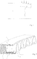
Fig. 1 ist eine Querschnittsansicht eines konventionellen, einteiligen Kolbenrings mit U-Profil; -
Fig. 2 ist eine Aufsicht einer Ausführungsform eines erfindungsgemäßen zweiteiligen Kolbenrings; -
Fig. 3 ist eine Querschnittsansicht durch eine weitere Ausführungsform eines erfindungsgemäßen zweiteiligen Kolbenrings; und -
Fig. 4 und 5 zeigen Mäanderprofile, die bei Ausführungsformen des erfindungsgemäßen Kolbenrings verwendet werden können. -
Figur 1 zeigt einen Querschnitt durch einen herkömmlichen einteiligen Kompressionskolbenring mit einem Grundkörper 2 mit U-förmigem Querschnitt. Während des Arbeitstakts des zugehörigen Motors liegt die untere Flanke 3 des Rings an der Ringnut (nicht gezeigt) an. Auf die obere Flanke 3 wirkt der Verbrennungsdruck beim Arbeitstakt des Motors, angedeutet durch Pfeile. Da die Flanke aufgrund des U-Profils eine wesentlich geringere Wandstärke aufweist als beispielsweise Rechteckringe, kann es zu einem Verbiegen der Flanke kommen, wie hier dargestellt.
Durch hohe Spitzenbelastung und/oder durch Ermüdung aufgrund andauernden Biegens im Betrieb kann es schließlich zum Brechen des Ringes kommen, etwa in der Gegend des Übergangs in die Schenkel des U-Profils. - Auch besitzt der gezeigte einteilige U-Profil-Kolbenring gegenüber einem Rechteckring mit ansonsten gleichen Abmessungen einen geringeren Radialdruck. Der Anpressdruck an die Zylinderlauffläche ist daher geringer.
- Zur Lösung dieser Probleme schlägt die Erfindung daher einen zweiteiligen Kolbenring vor.
Figur 2 zeigt eine Ausführungsform eines solchen Kolbenrings. Der Kolbenring 1 weist einen Grundkörper 2 mit U-förmigem Querschnitt auf. In der gezeigten Ausführungsform sind die radial nach innen weisenden Kanten der Schenkel des U-Querschnitts abgeschrägt. Alternativ sind ebenso rechteckige als auch gerundete Kanten oder Kombinationen davon möglich. - Im Inneren des U-Profils ist eine mäanderförmige Ringfeder 4 aufgenommen. In dem Abschnitt der Ringfeder 4, die innerhalb des Grundkörpers 2 aufgenommen ist, also sich zwischen den Schenkeln des U-Profils befindet, liegen die Mäanderschlaufen 5 abwechselnd an der oberen bzw. unteren Innenflanke des U-Profils an. In dem Abschnitt der Ringfeder 4, der aus dem Grundkörper 2 herausragt, liegen die Mäanderschlaufen 6 abwechselnd an den radial nach innen weisenden Kanten der Schenkel 3 des U-förmigen Querschnitts an.
- Dadurch besitzt der zweiteilige Kolbenring zwei vorteilhafte Eigenschaften gegenüber einem einteiligen U-förmigen Ring. Einerseits wird der Radialdruck durch die Ringfeder 4 erhöht, die den Grundkörper 2 durch das Anliegen an den radialen Innenkanten der Schenkel nach außen drücken kann. Andererseits stützen die innen liegenden Abschnitte der Ringfeder 4 die Schenkel bzw. Flanken 3 gegenüber Druckbelastungen in axialer Richtung ab. Ein Ringbrechen kann so vermieden werden.
- An den jeweiligen Maänderschlaufen befinden sich Schlitze, welche die inneren Maänderschlaufen 5 von den äußeren Mäanderschlaufen 6 trennen. Die Schlitze befinden sich beispielsweise im jeweiligen äußeren Drittel in Bezug auf die Höhe. Im mittleren Drittel hingegen ist die Ringfeder 4 einstückig. Andere Einteilungen sind ebenfalls möglich, solange ein ausreichend großer Bereich in der Mitte einstückig bleibt, um die Stabilität der Feder zu gewährleisten.
- Ebenso ist es lediglich optional, wie dargestellt eine symmetrische Feder zu verwenden, die auch im inneren Bereich durch Schlitze abgetrennte Mäanderschlaufen aufweist. Dies kann aus Gründen einer vereinfachten Herstellung der Feder wünschenswert sein, auch wenn die inneren Schlaufen am Rand dann funktionslos sind.
- Durch den relativ offenen Aufbau der Feder kann der Kolbenring auch bevorzugt als Kompressions- bzw. Top-Ring verwendet werden. Der Verbrennungsdruck kann an den offenen Stellen relativ ungehindert bis zur inneren Basisfläche des Grundkörpers vordringen und so den Kolbenring an die Zylinderlauffläche pressen. Dies ist ein Vorteil gegenüber massiveren Elementen zweiteiliger Kolbenringe, bei denen ein derartiger Gasdurchtritt nicht möglich ist.
-
Figur 3 zeigt eine alternative Ausführungsform des Kolbenrings im Querschnitt. Hier wird eine unsymmetrische Ringfeder 4 verwendet, die ausschließlich einen (breiteren) Innenbereich mit Mäanderschlaufen 5 sowie einen (schmaleren) Außenbereich mit Mäanderschlaufen 6 aufweist. Bei dem gezeigten Querschnitt liegen die jeweils unteren Mäanderschlaufen an dem unteren Schenkel des U-Profils an. Gestrichelt gezeigt sind die in Umfangsrichtung dahinter liegenden Schlaufen, die dann an dem oberen Schenkel anliegen. - Die
Figuren 4 und 5 zeigen Alternativen für die Mäanderform der Ringfeder. InFigur 4 sind (durchgezogen) trapezförmige Schlaufen sowie rechteckförmige Schlaufen (gestrichelt) gezeigt. In beiden Fällen gilt, dass hierdurch die bei wellenförmigen Maänderverläufen nur punkt- bzw. linienförmigen Anlagestellen an dem U-Profil durch flächigere Anlagen ersetzt werden. Das kann vorteilhaft sein, um die Kräfte gleichmäßiger verteilt einzuleiten. Außerdem kann durch steilere bis hin zu senkrechten Verläufen der Feder der Kolbenring in Axialrichtung besser gegen Biegemomente versteift werden. -
Figur 5 zeigt einen wellenförmigen Mäanderverlauf. Auch dieser kann durch Anpassung der Steilheit und/oder Anzahl der Schlaufen hinsichtlich der Abstützwirkung eingestellt werden.
wobei in einem Abschnitt der Ringfeder, der aus dem Grundkörper herausragt, Mäanderschlaufen abwechselnd an den radial nach innen weisenden Kanten der Schenkel des U-förmigen Querschnitts anliegen.
Claims (3)
- Kompressionskolbenring (1), umfassend:- einen vorzugsweise an einer Stoßstelle offenen ringförmigen Grundkörper (2) mit einem U-förmigem Querschnitt, dessen offene Seite in Radialrichtung nach innen weist;- eine in der Axialrichtung mäanderförmig verlaufende Ringfeder (4), die den Grundkörper (2) in Radialrichtung nach außen vorspannt;wobei in einem Abschnitt der Ringfeder (4), der innerhalb des Grundkörpers liegt, Mäanderschlaufen (5) abwechselnd an der oberen bzw. unteren Innenflanke der Schenkel (3) des U-förmigen Querschnitts anliegen, so dass die Schenkel (3) in axialer Richtung gegenüber Druckbelastungen abgestützt sind;
wobei in einem Abschnitt der Ringfeder (4), der aus dem Grundkörper (2) herausragt, äußere Mäanderschlaufen (6) abwechselnd an den radial nach innen weisenden Kanten der Schenkel (3) des U-förmigen Querschnitts anliegen. - Kolbenring (1) nach Anspruch 1, wobei der Grundkörper (2) und/oder das Innere des U-förmigen Querschnitts eine rechteckige Form aufweisen.
- Kolbenring (1) nach einem der vorhergehenden Ansprüche, wobei die Ringfeder (4) eine rechteckige, trapezförmige oder wellenförmige Mäanderform aufweist.
Applications Claiming Priority (2)
| Application Number | Priority Date | Filing Date | Title |
|---|---|---|---|
| DE102014223989.3A DE102014223989A1 (de) | 2014-11-25 | 2014-11-25 | Zweiteiliger Kolbenring |
| PCT/EP2015/071006 WO2016082955A1 (de) | 2014-11-25 | 2015-09-15 | Zweiteiliger kolbenring |
Publications (2)
| Publication Number | Publication Date |
|---|---|
| EP3224502A1 EP3224502A1 (de) | 2017-10-04 |
| EP3224502B1 true EP3224502B1 (de) | 2018-09-12 |
Family
ID=54106368
Family Applications (1)
| Application Number | Title | Priority Date | Filing Date |
|---|---|---|---|
| EP15763331.4A Not-in-force EP3224502B1 (de) | 2014-11-25 | 2015-09-15 | Zweiteiliger kolbenring |
Country Status (7)
| Country | Link |
|---|---|
| US (1) | US20170328471A1 (de) |
| EP (1) | EP3224502B1 (de) |
| JP (1) | JP6579342B2 (de) |
| CN (1) | CN107636287B (de) |
| DE (1) | DE102014223989A1 (de) |
| PT (1) | PT3224502T (de) |
| WO (1) | WO2016082955A1 (de) |
Family Cites Families (23)
| Publication number | Priority date | Publication date | Assignee | Title |
|---|---|---|---|---|
| US2220947A (en) * | 1938-06-30 | 1940-11-12 | Perfect Circle Co | Piston ring |
| US2635022A (en) * | 1950-06-20 | 1953-04-14 | Perfect Circle Corp | Piston ring assembly |
| US2815996A (en) * | 1955-02-14 | 1957-12-10 | Hastings Mfg Co | Piston ring assembly |
| US2917353A (en) * | 1957-04-18 | 1959-12-15 | Goetzewerke | Tensioning spring for piston rings |
| US2904377A (en) * | 1957-05-21 | 1959-09-15 | Muskegon Piston Ring Co Inc | Spacer and expander for piston rings |
| FR1280297A (fr) * | 1961-02-10 | 1961-12-29 | Wellworthy Ltd | Perfectionnements aux dispositifs annulaires d'étanchéité |
| US3378268A (en) * | 1963-12-12 | 1968-04-16 | Ramsey Corp | Piston ring assembly |
| US3212785A (en) * | 1964-01-13 | 1965-10-19 | Muskegon Piston Ring Co Inc | Oil ring |
| GB1413292A (en) * | 1972-07-12 | 1975-11-12 | Light Production Ltd | Piston rings |
| DE2504087A1 (de) * | 1975-01-31 | 1976-08-05 | Karlheinz Ern | Kolbenring |
| JPS51110154U (de) * | 1975-03-05 | 1976-09-06 | ||
| DE2557721B1 (de) * | 1975-12-20 | 1977-01-13 | Goetzewerke | Axial und radial spannender spreizfederring fuer oelabstreif-kolbenringe |
| JPS6018663A (ja) * | 1983-07-13 | 1985-01-30 | Riken Corp | 組合せオイルリング |
| US5195758A (en) * | 1991-11-19 | 1993-03-23 | Hastings Manufacturing Company | Three-piece oil control ring assembly |
| US5794941A (en) * | 1995-06-01 | 1998-08-18 | Dana Corporation | Piston ring assembly |
| JP3295598B2 (ja) * | 1996-07-05 | 2002-06-24 | 日産ディーゼル工業株式会社 | 内燃機関のピストンリング |
| DE19901284C1 (de) * | 1999-01-15 | 2000-07-27 | Federal Mogul Burscheid Gmbh | Ölabstreifkolbenring sowie Verfahren zum Einbau eines Ölabstreifkolbenringes |
| JP4382229B2 (ja) * | 2000-01-20 | 2009-12-09 | 帝国ピストンリング株式会社 | 組合せオイルリング |
| US7429047B1 (en) * | 2003-11-12 | 2008-09-30 | Mahle Engine Components Usa, Inc. | Piston ring assembly |
| JP4633639B2 (ja) * | 2006-01-31 | 2011-02-16 | 日本ピストンリング株式会社 | 3ピースオイルリング及び3ピースオイルリングとピストンとの組合せ |
| JP5557562B2 (ja) * | 2010-03-10 | 2014-07-23 | Tpr株式会社 | 組合せオイルリング |
| JP5587285B2 (ja) * | 2011-12-21 | 2014-09-10 | Tpr株式会社 | 組合せオイルリング |
| JP5970239B2 (ja) * | 2012-05-28 | 2016-08-17 | 株式会社リケン | 組合せオイルコントロールリング |
-
2014
- 2014-11-25 DE DE102014223989.3A patent/DE102014223989A1/de not_active Ceased
-
2015
- 2015-09-15 EP EP15763331.4A patent/EP3224502B1/de not_active Not-in-force
- 2015-09-15 US US15/529,232 patent/US20170328471A1/en not_active Abandoned
- 2015-09-15 PT PT15763331T patent/PT3224502T/pt unknown
- 2015-09-15 CN CN201580051330.6A patent/CN107636287B/zh not_active Expired - Fee Related
- 2015-09-15 JP JP2017522382A patent/JP6579342B2/ja not_active Expired - Fee Related
- 2015-09-15 WO PCT/EP2015/071006 patent/WO2016082955A1/de not_active Ceased
Non-Patent Citations (1)
| Title |
|---|
| None * |
Also Published As
| Publication number | Publication date |
|---|---|
| DE102014223989A1 (de) | 2016-05-25 |
| CN107636287A (zh) | 2018-01-26 |
| WO2016082955A1 (de) | 2016-06-02 |
| EP3224502A1 (de) | 2017-10-04 |
| US20170328471A1 (en) | 2017-11-16 |
| CN107636287B (zh) | 2020-08-07 |
| JP2017536514A (ja) | 2017-12-07 |
| JP6579342B2 (ja) | 2019-09-25 |
| PT3224502T (pt) | 2018-12-18 |
Similar Documents
| Publication | Publication Date | Title |
|---|---|---|
| EP2056003B1 (de) | Mehrteiliger Packungsring | |
| DE2055881A1 (de) | Ringdichtung | |
| DE4007252A1 (de) | Dichtungsanordnung fuer einen kompressorkolben | |
| EP2912351B1 (de) | Kolbenring | |
| EP3918232B1 (de) | Packungsring mit entlastungsöffnungen | |
| AT508131A4 (de) | Kolben mit kolbenringen und stützringen | |
| EP2570705A1 (de) | Abstreifring und Abstreiflamelle | |
| DE102007051414A1 (de) | Verbesserter Fluidaktuator für die Anwendung in Turbomaschinen | |
| EP3322922B1 (de) | Kompressionskolbenring mit profilierung | |
| DE3879825T2 (de) | Zylinderhaftdichtung mit einem brennraum-dichtelement, welches wie ein balken funktioniert. | |
| AT521648B1 (de) | Stützring, Dichtungsvorrichtung, Dichtungsanordnung und längenverstellbares Pleuel für eine Hubkolbenmaschine | |
| EP3798482A1 (de) | Dichtungseinstich für eine radiale dichtung | |
| DE102013200986A1 (de) | Dichtungsanordnung | |
| AT522985B1 (de) | Längenverstellbares Pleuel mit einer Dichtungsvorrichtung | |
| EP3918233B1 (de) | Packungsring mit schräger entlastungsöffnung | |
| EP3583308A1 (de) | Zylinder einer brennkraftmaschine | |
| WO2020015897A1 (de) | Mehrteiliger ölabstreif-kolbenring mit verringerter reibung | |
| EP3224502A1 (de) | Zweiteiliger kolbenring | |
| EP3325855B1 (de) | Kolbenring | |
| CH704934A2 (de) | Vakuumventil-Balg. | |
| WO2015040126A1 (de) | Kolben mit kolbenringnut, insbesondere kompressionsnut | |
| WO2013117183A1 (de) | Kolbenring für einen verbrennungsmotor | |
| DE102005024140B4 (de) | Dichtpaket und Hubkolben mit einem Dichtpaket | |
| WO2014079406A1 (de) | Kolben für einen verbrennungsmotor | |
| DE102016225875A1 (de) | Turbomaschinen-Dichtungsanordnung |
Legal Events
| Date | Code | Title | Description |
|---|---|---|---|
| STAA | Information on the status of an ep patent application or granted ep patent |
Free format text: STATUS: THE INTERNATIONAL PUBLICATION HAS BEEN MADE |
|
| PUAI | Public reference made under article 153(3) epc to a published international application that has entered the european phase |
Free format text: ORIGINAL CODE: 0009012 |
|
| STAA | Information on the status of an ep patent application or granted ep patent |
Free format text: STATUS: REQUEST FOR EXAMINATION WAS MADE |
|
| 17P | Request for examination filed |
Effective date: 20170213 |
|
| AK | Designated contracting states |
Kind code of ref document: A1 Designated state(s): AL AT BE BG CH CY CZ DE DK EE ES FI FR GB GR HR HU IE IS IT LI LT LU LV MC MK MT NL NO PL PT RO RS SE SI SK SM TR |
|
| AX | Request for extension of the european patent |
Extension state: BA ME |
|
| RIN1 | Information on inventor provided before grant (corrected) |
Inventor name: PROEPPER, JOERN Inventor name: RUCH, FABIAN |
|
| DAV | Request for validation of the european patent (deleted) | ||
| DAX | Request for extension of the european patent (deleted) | ||
| GRAP | Despatch of communication of intention to grant a patent |
Free format text: ORIGINAL CODE: EPIDOSNIGR1 |
|
| STAA | Information on the status of an ep patent application or granted ep patent |
Free format text: STATUS: GRANT OF PATENT IS INTENDED |
|
| INTG | Intention to grant announced |
Effective date: 20180514 |
|
| GRAS | Grant fee paid |
Free format text: ORIGINAL CODE: EPIDOSNIGR3 |
|
| GRAA | (expected) grant |
Free format text: ORIGINAL CODE: 0009210 |
|
| STAA | Information on the status of an ep patent application or granted ep patent |
Free format text: STATUS: THE PATENT HAS BEEN GRANTED |
|
| AK | Designated contracting states |
Kind code of ref document: B1 Designated state(s): AL AT BE BG CH CY CZ DE DK EE ES FI FR GB GR HR HU IE IS IT LI LT LU LV MC MK MT NL NO PL PT RO RS SE SI SK SM TR |
|
| REG | Reference to a national code |
Ref country code: GB Ref legal event code: FG4D Free format text: NOT ENGLISH |
|
| REG | Reference to a national code |
Ref country code: CH Ref legal event code: EP |
|
| REG | Reference to a national code |
Ref country code: FR Ref legal event code: PLFP Year of fee payment: 4 |
|
| REG | Reference to a national code |
Ref country code: IE Ref legal event code: FG4D Free format text: LANGUAGE OF EP DOCUMENT: GERMAN |
|
| REG | Reference to a national code |
Ref country code: DE Ref legal event code: R096 Ref document number: 502015005880 Country of ref document: DE |
|
| REG | Reference to a national code |
Ref country code: AT Ref legal event code: REF Ref document number: 1040987 Country of ref document: AT Kind code of ref document: T Effective date: 20181015 |
|
| REG | Reference to a national code |
Ref country code: SE Ref legal event code: TRGR |
|
| PGFP | Annual fee paid to national office [announced via postgrant information from national office to epo] |
Ref country code: FR Payment date: 20180921 Year of fee payment: 4 |
|
| PGFP | Annual fee paid to national office [announced via postgrant information from national office to epo] |
Ref country code: SE Payment date: 20180911 Year of fee payment: 4 |
|
| REG | Reference to a national code |
Ref country code: PT Ref legal event code: SC4A Ref document number: 3224502 Country of ref document: PT Date of ref document: 20181218 Kind code of ref document: T Free format text: AVAILABILITY OF NATIONAL TRANSLATION Effective date: 20181211 |
|
| REG | Reference to a national code |
Ref country code: NL Ref legal event code: MP Effective date: 20180912 |
|
| REG | Reference to a national code |
Ref country code: LT Ref legal event code: MG4D |
|
| PG25 | Lapsed in a contracting state [announced via postgrant information from national office to epo] |
Ref country code: LT Free format text: LAPSE BECAUSE OF FAILURE TO SUBMIT A TRANSLATION OF THE DESCRIPTION OR TO PAY THE FEE WITHIN THE PRESCRIBED TIME-LIMIT Effective date: 20180912 Ref country code: RS Free format text: LAPSE BECAUSE OF FAILURE TO SUBMIT A TRANSLATION OF THE DESCRIPTION OR TO PAY THE FEE WITHIN THE PRESCRIBED TIME-LIMIT Effective date: 20180912 Ref country code: BG Free format text: LAPSE BECAUSE OF FAILURE TO SUBMIT A TRANSLATION OF THE DESCRIPTION OR TO PAY THE FEE WITHIN THE PRESCRIBED TIME-LIMIT Effective date: 20181212 Ref country code: GR Free format text: LAPSE BECAUSE OF FAILURE TO SUBMIT A TRANSLATION OF THE DESCRIPTION OR TO PAY THE FEE WITHIN THE PRESCRIBED TIME-LIMIT Effective date: 20181213 Ref country code: NO Free format text: LAPSE BECAUSE OF FAILURE TO SUBMIT A TRANSLATION OF THE DESCRIPTION OR TO PAY THE FEE WITHIN THE PRESCRIBED TIME-LIMIT Effective date: 20181212 Ref country code: FI Free format text: LAPSE BECAUSE OF FAILURE TO SUBMIT A TRANSLATION OF THE DESCRIPTION OR TO PAY THE FEE WITHIN THE PRESCRIBED TIME-LIMIT Effective date: 20180912 |
|
| PGFP | Annual fee paid to national office [announced via postgrant information from national office to epo] |
Ref country code: PT Payment date: 20181218 Year of fee payment: 4 |
|
| PG25 | Lapsed in a contracting state [announced via postgrant information from national office to epo] |
Ref country code: HR Free format text: LAPSE BECAUSE OF FAILURE TO SUBMIT A TRANSLATION OF THE DESCRIPTION OR TO PAY THE FEE WITHIN THE PRESCRIBED TIME-LIMIT Effective date: 20180912 Ref country code: AL Free format text: LAPSE BECAUSE OF FAILURE TO SUBMIT A TRANSLATION OF THE DESCRIPTION OR TO PAY THE FEE WITHIN THE PRESCRIBED TIME-LIMIT Effective date: 20180912 Ref country code: LV Free format text: LAPSE BECAUSE OF FAILURE TO SUBMIT A TRANSLATION OF THE DESCRIPTION OR TO PAY THE FEE WITHIN THE PRESCRIBED TIME-LIMIT Effective date: 20180912 |
|
| PG25 | Lapsed in a contracting state [announced via postgrant information from national office to epo] |
Ref country code: RO Free format text: LAPSE BECAUSE OF FAILURE TO SUBMIT A TRANSLATION OF THE DESCRIPTION OR TO PAY THE FEE WITHIN THE PRESCRIBED TIME-LIMIT Effective date: 20180912 Ref country code: CZ Free format text: LAPSE BECAUSE OF FAILURE TO SUBMIT A TRANSLATION OF THE DESCRIPTION OR TO PAY THE FEE WITHIN THE PRESCRIBED TIME-LIMIT Effective date: 20180912 Ref country code: NL Free format text: LAPSE BECAUSE OF FAILURE TO SUBMIT A TRANSLATION OF THE DESCRIPTION OR TO PAY THE FEE WITHIN THE PRESCRIBED TIME-LIMIT Effective date: 20180912 Ref country code: IS Free format text: LAPSE BECAUSE OF FAILURE TO SUBMIT A TRANSLATION OF THE DESCRIPTION OR TO PAY THE FEE WITHIN THE PRESCRIBED TIME-LIMIT Effective date: 20190112 Ref country code: EE Free format text: LAPSE BECAUSE OF FAILURE TO SUBMIT A TRANSLATION OF THE DESCRIPTION OR TO PAY THE FEE WITHIN THE PRESCRIBED TIME-LIMIT Effective date: 20180912 Ref country code: PL Free format text: LAPSE BECAUSE OF FAILURE TO SUBMIT A TRANSLATION OF THE DESCRIPTION OR TO PAY THE FEE WITHIN THE PRESCRIBED TIME-LIMIT Effective date: 20180912 Ref country code: ES Free format text: LAPSE BECAUSE OF FAILURE TO SUBMIT A TRANSLATION OF THE DESCRIPTION OR TO PAY THE FEE WITHIN THE PRESCRIBED TIME-LIMIT Effective date: 20180912 |
|
| PGFP | Annual fee paid to national office [announced via postgrant information from national office to epo] |
Ref country code: IT Payment date: 20180930 Year of fee payment: 4 |
|
| REG | Reference to a national code |
Ref country code: CH Ref legal event code: PL |
|
| PG25 | Lapsed in a contracting state [announced via postgrant information from national office to epo] |
Ref country code: SM Free format text: LAPSE BECAUSE OF FAILURE TO SUBMIT A TRANSLATION OF THE DESCRIPTION OR TO PAY THE FEE WITHIN THE PRESCRIBED TIME-LIMIT Effective date: 20180912 Ref country code: SK Free format text: LAPSE BECAUSE OF FAILURE TO SUBMIT A TRANSLATION OF THE DESCRIPTION OR TO PAY THE FEE WITHIN THE PRESCRIBED TIME-LIMIT Effective date: 20180912 |
|
| REG | Reference to a national code |
Ref country code: BE Ref legal event code: MM Effective date: 20180930 |
|
| REG | Reference to a national code |
Ref country code: DE Ref legal event code: R097 Ref document number: 502015005880 Country of ref document: DE |
|
| REG | Reference to a national code |
Ref country code: IE Ref legal event code: MM4A |
|
| PG25 | Lapsed in a contracting state [announced via postgrant information from national office to epo] |
Ref country code: LU Free format text: LAPSE BECAUSE OF NON-PAYMENT OF DUE FEES Effective date: 20180915 |
|
| PLBE | No opposition filed within time limit |
Free format text: ORIGINAL CODE: 0009261 |
|
| STAA | Information on the status of an ep patent application or granted ep patent |
Free format text: STATUS: NO OPPOSITION FILED WITHIN TIME LIMIT |
|
| PG25 | Lapsed in a contracting state [announced via postgrant information from national office to epo] |
Ref country code: IE Free format text: LAPSE BECAUSE OF NON-PAYMENT OF DUE FEES Effective date: 20180915 Ref country code: MC Free format text: LAPSE BECAUSE OF FAILURE TO SUBMIT A TRANSLATION OF THE DESCRIPTION OR TO PAY THE FEE WITHIN THE PRESCRIBED TIME-LIMIT Effective date: 20180912 Ref country code: DK Free format text: LAPSE BECAUSE OF FAILURE TO SUBMIT A TRANSLATION OF THE DESCRIPTION OR TO PAY THE FEE WITHIN THE PRESCRIBED TIME-LIMIT Effective date: 20180912 |
|
| 26N | No opposition filed |
Effective date: 20190613 |
|
| PG25 | Lapsed in a contracting state [announced via postgrant information from national office to epo] |
Ref country code: SI Free format text: LAPSE BECAUSE OF FAILURE TO SUBMIT A TRANSLATION OF THE DESCRIPTION OR TO PAY THE FEE WITHIN THE PRESCRIBED TIME-LIMIT Effective date: 20180912 Ref country code: BE Free format text: LAPSE BECAUSE OF NON-PAYMENT OF DUE FEES Effective date: 20180930 Ref country code: CH Free format text: LAPSE BECAUSE OF NON-PAYMENT OF DUE FEES Effective date: 20180930 Ref country code: LI Free format text: LAPSE BECAUSE OF NON-PAYMENT OF DUE FEES Effective date: 20180930 |
|
| PG25 | Lapsed in a contracting state [announced via postgrant information from national office to epo] |
Ref country code: MT Free format text: LAPSE BECAUSE OF FAILURE TO SUBMIT A TRANSLATION OF THE DESCRIPTION OR TO PAY THE FEE WITHIN THE PRESCRIBED TIME-LIMIT Effective date: 20180912 |
|
| PG25 | Lapsed in a contracting state [announced via postgrant information from national office to epo] |
Ref country code: TR Free format text: LAPSE BECAUSE OF FAILURE TO SUBMIT A TRANSLATION OF THE DESCRIPTION OR TO PAY THE FEE WITHIN THE PRESCRIBED TIME-LIMIT Effective date: 20180912 |
|
| PG25 | Lapsed in a contracting state [announced via postgrant information from national office to epo] |
Ref country code: SE Free format text: LAPSE BECAUSE OF NON-PAYMENT OF DUE FEES Effective date: 20190916 |
|
| REG | Reference to a national code |
Ref country code: SE Ref legal event code: EUG |
|
| PG25 | Lapsed in a contracting state [announced via postgrant information from national office to epo] |
Ref country code: HU Free format text: LAPSE BECAUSE OF FAILURE TO SUBMIT A TRANSLATION OF THE DESCRIPTION OR TO PAY THE FEE WITHIN THE PRESCRIBED TIME-LIMIT; INVALID AB INITIO Effective date: 20150915 Ref country code: MK Free format text: LAPSE BECAUSE OF NON-PAYMENT OF DUE FEES Effective date: 20180912 Ref country code: CY Free format text: LAPSE BECAUSE OF FAILURE TO SUBMIT A TRANSLATION OF THE DESCRIPTION OR TO PAY THE FEE WITHIN THE PRESCRIBED TIME-LIMIT Effective date: 20180912 |
|
| PG25 | Lapsed in a contracting state [announced via postgrant information from national office to epo] |
Ref country code: IT Free format text: LAPSE BECAUSE OF NON-PAYMENT OF DUE FEES Effective date: 20190915 |
|
| GBPC | Gb: european patent ceased through non-payment of renewal fee |
Effective date: 20190915 |
|
| PG25 | Lapsed in a contracting state [announced via postgrant information from national office to epo] |
Ref country code: PT Free format text: LAPSE BECAUSE OF NON-PAYMENT OF DUE FEES Effective date: 20200714 Ref country code: GB Free format text: LAPSE BECAUSE OF NON-PAYMENT OF DUE FEES Effective date: 20190915 |
|
| PG25 | Lapsed in a contracting state [announced via postgrant information from national office to epo] |
Ref country code: FR Free format text: LAPSE BECAUSE OF NON-PAYMENT OF DUE FEES Effective date: 20190930 |
|
| REG | Reference to a national code |
Ref country code: AT Ref legal event code: MM01 Ref document number: 1040987 Country of ref document: AT Kind code of ref document: T Effective date: 20200915 |
|
| PG25 | Lapsed in a contracting state [announced via postgrant information from national office to epo] |
Ref country code: AT Free format text: LAPSE BECAUSE OF NON-PAYMENT OF DUE FEES Effective date: 20200915 |
|
| PGFP | Annual fee paid to national office [announced via postgrant information from national office to epo] |
Ref country code: DE Payment date: 20220818 Year of fee payment: 8 |
|
| P01 | Opt-out of the competence of the unified patent court (upc) registered |
Effective date: 20230528 |
|
| REG | Reference to a national code |
Ref country code: DE Ref legal event code: R119 Ref document number: 502015005880 Country of ref document: DE |
|
| PG25 | Lapsed in a contracting state [announced via postgrant information from national office to epo] |
Ref country code: DE Free format text: LAPSE BECAUSE OF NON-PAYMENT OF DUE FEES Effective date: 20240403 |