EP3222158A1 - Machine et procédé de fabrication de filtres de cigarette - Google Patents
Machine et procédé de fabrication de filtres de cigarette Download PDFInfo
- Publication number
- EP3222158A1 EP3222158A1 EP17162760.7A EP17162760A EP3222158A1 EP 3222158 A1 EP3222158 A1 EP 3222158A1 EP 17162760 A EP17162760 A EP 17162760A EP 3222158 A1 EP3222158 A1 EP 3222158A1
- Authority
- EP
- European Patent Office
- Prior art keywords
- tow
- feed line
- feed
- stream
- garniture tongue
- Prior art date
- Legal status (The legal status is an assumption and is not a legal conclusion. Google has not performed a legal analysis and makes no representation as to the accuracy of the status listed.)
- Granted
Links
Images


Classifications
-
- A—HUMAN NECESSITIES
- A24—TOBACCO; CIGARS; CIGARETTES; SIMULATED SMOKING DEVICES; SMOKERS' REQUISITES
- A24D—CIGARS; CIGARETTES; TOBACCO SMOKE FILTERS; MOUTHPIECES FOR CIGARS OR CIGARETTES; MANUFACTURE OF TOBACCO SMOKE FILTERS OR MOUTHPIECES
- A24D3/00—Tobacco smoke filters, e.g. filter-tips, filtering inserts; Filters specially adapted for simulated smoking devices; Mouthpieces for cigars or cigarettes
- A24D3/02—Manufacture of tobacco smoke filters
- A24D3/0275—Manufacture of tobacco smoke filters for filters with special features
- A24D3/0279—Manufacture of tobacco smoke filters for filters with special features with tubes
-
- A—HUMAN NECESSITIES
- A24—TOBACCO; CIGARS; CIGARETTES; SIMULATED SMOKING DEVICES; SMOKERS' REQUISITES
- A24D—CIGARS; CIGARETTES; TOBACCO SMOKE FILTERS; MOUTHPIECES FOR CIGARS OR CIGARETTES; MANUFACTURE OF TOBACCO SMOKE FILTERS OR MOUTHPIECES
- A24D3/00—Tobacco smoke filters, e.g. filter-tips, filtering inserts; Filters specially adapted for simulated smoking devices; Mouthpieces for cigars or cigarettes
- A24D3/02—Manufacture of tobacco smoke filters
- A24D3/0275—Manufacture of tobacco smoke filters for filters with special features
- A24D3/0287—Manufacture of tobacco smoke filters for filters with special features for composite filters
-
- A—HUMAN NECESSITIES
- A24—TOBACCO; CIGARS; CIGARETTES; SIMULATED SMOKING DEVICES; SMOKERS' REQUISITES
- A24D—CIGARS; CIGARETTES; TOBACCO SMOKE FILTERS; MOUTHPIECES FOR CIGARS OR CIGARETTES; MANUFACTURE OF TOBACCO SMOKE FILTERS OR MOUTHPIECES
- A24D3/00—Tobacco smoke filters, e.g. filter-tips, filtering inserts; Filters specially adapted for simulated smoking devices; Mouthpieces for cigars or cigarettes
- A24D3/04—Tobacco smoke filters characterised by their shape or structure
Definitions
- This invention relates to a machine and a method for making cigarette filters.
- Filters for cigarettes, or for other smokers' articles such as cigars come in many different forms which differ, for example, in the type of filter material used to make them or the flavours that can be added to them; these forms may be broadly divided into two types.
- a first, “traditional” type of filter uses a cylindrical body of soft filter material enclosed in a wrapper; the filter material is usually tow and is subjected to specific treatment to give it the technical characteristics needed to form the cylindrical filter.
- a second, “combined” filter type comprises two or more filter plugs placed in a wrapper and aligned along the longitudinal axis of the filter in a predetermined sequence; generally speaking, the filter plugs making up the filter differ in material used or flavour added.
- Machines for making traditional filters have a section which is configured to process the tow to form the cylindrical filter body, which is fed to a garniture tongue where it is wrapped in paper and which is then cut into individual filters.
- a section which is configured to process the tow to form the cylindrical filter body, which is fed to a garniture tongue where it is wrapped in paper and which is then cut into individual filters.
- Machines for making combined filters known as "combiners” have a system of rollers capable of withdrawing different filter plugs from a reservoir and combining them into groups of sequentially ordered filter plugs; the groups are then fed to a garniture tongue which wraps them. Examples of machines of this type are described in patent documents EP2145551 and US8992400 in the name of the same Applicant as this invention.
- This invention has for an aim to provide a machine and a method for making cigarette filters to overcome the above mentioned disadvantages of the prior art.
- the aim of this invention is to provide a particularly versatile machine and method for making cigarette filters.
- a further aim of the invention is to provide a machine and a method which allow making a wide range of cigarette filters in a rapid and precise manner.
- Another aim of the invention is to provide a machine and a method which allow making in a rapid and precise manner a wide range of cigarette filters having a tubular body made of tow, with the possibility of inserting further filter elements into the tubular body.
- the machine according to this description is a machine for making filters for cigarettes (or similar smokers' articles such as filter cigars, for example).
- the machine has a garniture tongue.
- the garniture tongue has an elongate groove extending along a longitudinal axis; the groove is preferably rounded.
- the function of the garniture tongue is to receive the materials needed to make the filters and to form a continuous rod feeding out of the garniture tongue itself along the longitudinal axis.
- the machine also comprises a feed section for feeding the garniture tongue with the materials needed to form the rod.
- the machine preferably also comprises a cutting station for cutting the rod into portions; these portions constitute individual filters or combined groups of filters which can be divided by further cutting.
- the machine may be provided with a further garniture tongue for forming a further rod at the same time as the first rod; this solution allows increasing the production capacity of the machine and substantially involves doubling the feed section, which substantially means that the machine has a first and a second feed section (whilst the cutting station may be in common for both of the rods).
- the feed section includes a first feed line configured to feed a strip of paper to the garniture tongue.
- the paper used in the first feed line may have a grammage in the interval [20; 130] gsm; preferably, the grammage is in the interval [25; 30] gsm; in one example embodiment, the grammage is in the interval [50; 70] gsm; in another example embodiment, the grammage is in the interval [90; 130] gsm.
- the first feed line is provided with a roll from which the strip of paper is unwound.
- the first feed line is also provided with a gumming unit configured to apply an adhesive substance on the paper strip; the gumming unit is preferably located upstream of the garniture tongue.
- upstream and downstream refer to a direction of movement of a web or strip (for example, of paper or tow) or of elements (such as the filter plugs) from an accumulation zone (roll of paper or bale of tow or reservoir of filter elements, for example, from which the web or strip is fed) towards the cutting station or towards an outfeed end of the machine.
- the feed section also includes a second feed line configured to feed a stream of processed and shaped tow to the garniture tongue.
- the second feed line has a tank containing a web of tow, for example in the form of a bale of folded and pressed web of tow.
- the second feed line also comprises a processing unit configured to subject the web of tow (from the tank) to stresses of various kinds (for example, mechanical or chemical).
- mechanical stresses the processing unit is preferably configured to subject the web of tow to stretching; preferably, the stretching is both longitudinal (that is, directed along a web unwinding direction) and transverse to the web.
- the processing unit is preferably configured to add triacetin to the tow (the web is soaked in triacetin).
- the processing unit is configured to blow steam onto the web.
- the second feed line also comprises a shaping device, located downstream of the processing unit to receive the stream of processed tow from the processing unit.
- the shaping device is configured to manipulate the stream of tow to form it into a predetermined shape.
- the second feed line feeds the garniture tongue with the stream of tow which has been processed and given the predetermined shape.
- the feed section also includes a third feed line; the third feed line acts in conjunction with the first and second feed lines to feed the same garniture tongue.
- the third feed line has a reservoir containing filter plugs.
- the reservoir contains filter plugs of different kinds; for example, the reservoir comprises a plurality of containers (for example, hoppers) each containing filter elements of the same kind.
- the third feed line also has a combining unit configured to form groups of filter plugs ordered in sequence.
- the third feed line also has a positioning device configured to pick up the groups of filter plugs and place them in the garniture tongue.
- the positioning device is, for example, a "spider" device.
- the spider is made according to technology of essentially known type, as described, for example, in patent document WO2015044848 or EP1787534A1 or EP2145551 or US8992400 .
- the first, second and third feed lines to feed the same garniture tongue make the machine more versatile because they allow making filters which integrate a body of tow extending longitudinally the full length of the filter with a group of plugs ordered in sequence.
- Another aspect of this description regards the shaping device of the second feed line.
- the shaping device is configured to give the stream of processed tow the shape of a ribbon, having a transverse cross section with a flat shape.
- flat shape is used to mean a “substantially rectangular” shape.
- the expression “flat” or “substantially rectangular” shape means that the cross section has two long sides and two short sides, where the long sides are parallel to each other and the short sides are designed to join the long sides but may have different shapes; for example, the short sides may be zig-zag shaped or curved or they may be single straight lines inclined to the long sides to form a parallelogram. in this context, a true rectangular shape would be obtained in the specific case where the long and short sides of the parallelogram are at right angles to each other.
- the machine (in particular the second feed line) comprises a first and a second shaping device, interchangeable with each other, where the first shaping device is configured to give the stream of processed tow a first shape and the second shaping device is configured to give the stream of processed tow a second shape, different from the first shape.
- the possibility of varying the shape of the stream of tow fed to the garniture tongue increases the versatility of the machine because it allows making filters whose tow bodies (preferably extending longitudinally the full length of the filter) have different shapes.
- the first shaping device is configured to give the stream of processed tow the aforementioned ribbon shape (which might constitute the first shape).
- the second shaping device is configured to give the stream of processed tow the shape of a rope (or string), with a circular cross section; this shape might constitute the second shape.
- the machine comprises a folding unit configured to fold the ribbon of tow to form a tube of tow which is coaxial with the longitudinal axis of the garniture tongue; preferably, the tube of tow has a transverse cross section having the shape of a circular crown.
- the folding unit is configured to fold the ribbon of tow about the longitudinal axis of the garniture tongue.
- the machine comprises a joining unit configured to permanently join a first and a second lateral edge of the ribbon of tow folded into the shape of a tube.
- the joining unit is configured to join the first and second lateral edges of the ribbon of tow along a generator of the tube of tow.
- the joining unit comprises a dispenser of adhesive material located at a stationary position on the garniture tongue to spread adhesive material on at least one of the lateral edges of the ribbon of tow.
- the joining unit comprises, alternatively or in addition to the dispenser, a heater configured to transmit heat to the tow positioned in the garniture tongue.
- the folding unit and the joining unit form part of the garniture tongue of the machine.
- the garniture tongue comprises a heater configured to transmit heat to the tube of tow; the heater may wholly or partly define the joining unit; whatever the case, the heater may also have the function of hardening the (tube of) tow by accelerating the activation of the triacetin contained in the tow.
- the shaping device might comprise one or more heating elements for transferring heat to the stream of processed tow.
- the first shaping device that is, the one configured to form the ribbon of tow (used to form the tube of tow) which comprises the one or more heating elements.
- the (first) shaping device (configured to form the ribbon of tow) comprises at least one roller, defining a shaped groove, and a belt interacting with the roller to push the stream of tow into the shaped groove.
- the belt is preferably motor-driven; preferably, the belt is trained around a plurality of pulleys and has one stretch disposed along a circular arc and facing a corresponding portion of the groove of the roller (the groove runs along a circle defined by the periphery of the roller).
- the (first) shaping device (configured to form the ribbon of tow) comprises a first and a second roller which are counter-rotating and each of which is provided with a respective shaped groove.
- This shaping device preferably also comprises a first and a second motor-driven belt acting in conjunction with the first and second roller, respectively, to push the stream of tow into the corresponding shaped grooves.
- the rollers are preferably heated and constitute the heating elements (one heating element in the case of a single roller and two heating elements in the case of two rollers).
- the shaping device comprises a conveyor configured to feed the previously processed stream of tow; this conveyor is, for example, a nozzle.
- the conveyor is configured to feed the stream of tow into a space defined between the first belt and the groove of the first roller.
- the shape of the stream feeding out of the conveyor is suitable to be inserted and squeezed into the groove, which, for example, may have a cylindrical, elliptic or flat shape; this shape may initially be an approximate shape and the ribbon is then given the exact shape required as a result of the interaction between the belt and the roller.
- the conveyor might comprise a nozzle having an outfeed opening having the flat shape required as the final shape of the ribbon. Preferably, in this case, the nozzle is heated.
- the flat cross section given to the stream of tow has thin lateral portions; for example, the flat cross section given to the stream of tow has the shape of a parallelogram.
- the first and second grooves of the first and second rollers have a radial cross section which has the shape of a right-angled trapezium.
- the machine is preferably a modular machine to make it easier to change the machine settings during changeovers.
- the machine comprises a first module and a second module which are interchangeable, where the first and second modules define corresponding combining units of the third feed line.
- the combining unit of the first module is configured to process filter plugs having a first diameter and the combining unit of the second module is configured to process filter plugs having a second diameter, different from the first diameter.
- An example of a situation where the machine requires the modules of the combining unit to be substituted is when changing over between a filter having filter plugs wrapped directly in the strip of paper (in this case, the filter plugs will have a first diameter) and a filter having filter plugs inserted in a tube of tow (in this case, the filter plugs will have a second diameter which, to maintain the same total diameter of the filter, is less than the first diameter because the thickness of the tube of tow is greater than the thickness of the strip of paper.
- the garniture tongue has an infeed end, where it receives the materials from the feed section, and an outfeed end, where the cutting station is located.
- the rod is moved along the longitudinal axis of the garniture tongue in a feed direction from the infeed end to the outfeed end of the garniture tongue.
- the first feed line is preferably located at a level below the (groove of the) garniture tongue.
- the first feed line is configured to unwind the strip of paper along a path contained in a vertical plane (perpendicular to the floor the machine rests on) containing the longitudinal axis.
- the first feed line is preferably located at an advanced position relative to the garniture tongue; preferably, this (advanced) position is a position which, vertically, is substantially aligned with the infeed end of the garniture tongue.
- the second feed line is located at a position behind the first feed line with reference to the feed direction.
- the second feed line is configured to unwind the tow (web or stream) along a path contained in a vertical plane (perpendicular to the floor the machine rests on) containing the longitudinal axis.
- the second feed line is located at a level (height from the floor) of 60-120 cm, preferably 80 cm.
- the third feed line is located at a level (height from the floor) of 170-220 cm, preferably 190-200 cm.
- the third feed line is located at a position behind the first feed line with reference to the feed direction.
- the third feed line is configured to move the filter plugs along a path contained in a vertical plane (perpendicular to the floor the machine rests on) containing the longitudinal axis.
- the combining unit of the third feed line is located at a level higher than the second feed line; preferably, the combining unit of the third feed line is located above the second feed line.
- the tow tank of the third feed line is located at a position behind the second feed line and behind the combining unit of the third feed line, with reference to the feed direction.
- the third feed line might also extend transversely relative to the longitudinal axis of the garniture tongue (and relative to the second feed line).
- first, second and third feed lines each have an activated configuration and a deactivated configuration; preferably, the first, second and third feed lines can each be set to the activated or deactivated configuration independently of the configuration of the other feed lines.
- the feed line In the activated configuration, the feed line is operatively coupled to and feeds the garniture tongue; in the deactivated configuration, the feed line is operatively uncoupled to and does not feed the garniture tongue.
- the machine according to this description can be set to one or more (and preferably to all) of the following operating configurations. It should be noted that the following operating configurations are operating configurations of the feed section and, more in general, of the machine.
- the first feed line is activated, the second feed line is activated and the third feed line is deactivated, so that the garniture tongue is operatively coupled to the first and second feed lines (but not to the third feed line) to receive the stream of processed and shaped tow and the paper strip without receiving the groups of filter plugs.
- the second shaping device of the second feed line is configured to form the tow into the rope shape.
- the machine is configured to make filters of a first type, consisting of a cylindrical body of tow (extending the full length of the filter) wrapped in a layer of paper.
- a second operating configuration is like the first operating configuration except that the first shaping device (and not the second) of the second feed line is configured to form the tow into the ribbon shape.
- the garniture tongue is configured to form the tube of tow from the ribbon.
- the machine is configured to make filters of a second type, consisting of a tubular body of tow (extending the full length of the filter) wrapped in a layer of paper and internally hollow to form an empty passage inside it.
- the first feed line is deactivated, the second feed line is activated and the third feed line is deactivated, so that the garniture tongue is operatively coupled to the second feed line (and uncoupled from the first and third feed lines) to receive the stream of processed and shaped tow, without receiving either the groups of filter plugs or the paper strip.
- the second shaping device of the second feed line is configured to form the tow into the rope shape.
- the machine is configured to make filters of a third type, consisting of a cylindrical body of tow (extending the full length of the filter) without the overwrap.
- a fourth operating configuration is like the third operating configuration except that the first shaping device (and not the second) of the second feed line is configured to form the tow into the ribbon shape.
- the garniture tongue is configured to form the tube of tow from the ribbon.
- the machine is configured to make filters of a fourth type, consisting of a tubular body of tow (extending the full length of the filter) without overwrapping and internally hollow to form an empty passage inside it.
- the first feed line is activated, the second feed line is deactivated and the third feed line is activated, so that the garniture tongue is operatively coupled to the first and third feed lines (and uncoupled from the second feed line) to receive the groups of filter plugs in ordered sequence and the paper strip, without receiving the stream of tow.
- the machine is configured to make filters of a fifth type, consisting of a group of filter plugs ordered in a predetermined sequence and wrapped in an external layer (of paper).
- the first feed line is deactivated, the second feed line is activated and the third feed line is activated, so that the garniture tongue is operatively coupled to the second and third feed lines (and uncoupled from the first feed line) to receive the stream of processed and shaped tow and the groups of filter plugs in ordered sequence, without receiving the paper strip.
- the first shaping device of the second feed line is configured to form the tow into the ribbon shape.
- the garniture tongue is configured to form the tube of tow from the ribbon.
- the machine is configured to make filters of a sixth type, consisting of a tubular body of tow (extending the full length of the filter) without overwrapping and containing a group of filter plugs ordered in a predetermined sequence inside it.
- the first feed line is activated, the second feed line is activated and the third feed line is activated, so that the garniture tongue is operatively coupled to the first, second and third feed lines to receive the stream of processed and shaped tow, the groups of filter plugs in ordered sequence and the paper strip.
- the first shaping device of the second feed line is configured to form the tow into the ribbon shape.
- the garniture tongue is configured to form the tube of tow from the ribbon.
- the machine is configured to make filters of a seventh type, consisting of a tubular body of tow (extending the full length of the filter) overwrapped and containing a group of filter plugs ordered in a predetermined sequence inside it. It should be noted that the operating configurations described above (from the first to the seventh) are alternative to each other.
- This description also provides a machine for making filters for cigarettes (or similar smokers' articles such as filter cigars, for example) where the feed section includes the first and second feed lines but does not have the third feed line.
- the shaping device of the second feed line is preferably configured to form the ribbon of tow and the garniture tongue is preferably configured to fold the ribbon of tow to form the tube of tow from the ribbon (according to one or more of the features contained in this description).
- This description also provides a method for making filters for cigarettes (or other filter-tipped smokers' articles).
- the method comprises a step of conveying materials used to form the filters to a garniture tongue defining an elongate groove extending along a longitudinal axis.
- the method also comprises a step of cutting the rod into portions constituting corresponding filters or groups of filters combined in a single portion.
- the conveying step in turn comprises the following steps:
- the first, second and third feeding steps can each be enabled and disabled independently of the other steps.
- the processed tow is formed according to a first shaping mode and according to a second shaping mode, with the possibility of switching from the first to the second shaping mode and vice versa.
- the stream of tow is formed into the shape of a ribbon having a flat (substantially rectangular) transverse cross section.
- the stream of tow is formed into the shape of a rope having a circular transverse cross section.
- the step of forming the rod includes a step of folding the ribbon of tow about the longitudinal axis and a step of permanently joining a first and a second lateral edge of the ribbon of tow to form a tube of tow having a transverse cross section in the shape of a circular crown.
- the method comprises setting one or more (preferably all) of the following operating (process) configurations; these operating (process) configurations are alternative to each other.
- the method preferably comprises a preliminary step of setting the operating configuration, as a function of which the other steps of the method are enabled or disabled or may adopt particular settings.
- the first feeding step is enabled, the second feeding step is enabled and the third feeding step is disabled, so as to feed the garniture tongue with the stream of processed and shaped tow and with the paper strip, without feeding the groups of filter plugs.
- the tow is shaped in the second mode (rope shape).
- the method allows making the filters of the first type.
- a second operating (process) configuration is like the first, except that the tow is shaped in the first mode (ribbon shape) and forming comprises forming the tube of tow.
- the method allows making the filters of the second type.
- the first feeding step is disabled, the second feeding step is enabled and the third feeding step is disabled, so as to feed the garniture tongue with the stream of processed and shaped tow, without feeding either the groups of filter plugs or the paper strip.
- the tow is shaped in the second mode (rope shape).
- the method allows making the filters of the third type.
- a fourth operating (process) configuration is like the third, except that the tow is shaped in the first mode (ribbon shape) and forming comprises forming the tube of tow.
- the method allows making the filters of the fourth type.
- the first feeding step is enabled, the second feeding step is disabled and the third feeding step is enabled, so as to feed the garniture tongue with the groups of filter plugs ordered in sequence and with the paper strip, without feeding the stream of tow..
- the method allows making the filters of the fifth type.
- the first feeding step is disabled, the second feeding step is enabled and the third feeding step is enabled, so as to feed the garniture tongue with the stream of processed and shaped tow and with the groups of filter plugs ordered in sequence, without feeding the paper strip.
- the tow is shaped in the first mode (ribbon shape) and forming comprises forming the tube of tow.
- the method allows making the filters of the sixth type.
- a seventh operating (process) configuration the first feeding step is enabled, the second feeding step is enabled and the third feeding step is enabled, so as to feed the garniture tongue with the stream of processed and shaped tow, with the groups of filter plugs ordered in sequence and with the paper strip.
- the tow is shaped in the first mode (ribbon shape) and forming comprises forming the tube of tow.
- the method allows making the filters of the seventh type.
- This description also provides a filter for cigarettes or other filter-tipped smokers' articles.
- This filter can be made using the machine according to this description or the method according to this description.
- the filter comprises a tubular body of tow which is elongate along a longitudinal axis and having a transverse cross section in the shape of a circular crown.
- the tubular body of tow extends the full (longitudinal) length of the filter.
- the tubular body has a joining zone located along a generator of the tubular body, in which opposite edges of a layer of tow folded into the shape of tube are joined together.
- the filter may comprise a layer of paper (wrapping) placed round the outside of the tubular body and in contact therewith; in an alternative embodiment, the filter does not have this wrapping.
- the filter comprises a plurality of filter plugs (cylindrical in shape or in any case whose cross section can be inscribed in a circle) positioned inside the tubular body and aligned in sequence along the longitudinal axis.
- the tubular body is internally hollow, thus defining a through hole.
- the numeral 1 in the drawings denotes a machine according to this description.
- the machine 1 is a machine for making filters 2 for cigarettes or for other filter-tipped smokers' articles.
- the machine 1 comprises a garniture tongue 3.
- the garniture tongue 3 is elongate along a longitudinal axis 301.
- the garniture tongue 3 has a groove 302 oriented along the longitudinal axis 301.
- the groove 302 is preferably rounded and its concavity faces upwards.
- the garniture tongue 3 includes a folding tape 303 for folding a layer of material (for example, paper or tow) into a cylindrical shape about the longitudinal axis 301 of the garniture tongue 3.
- the garniture tongue 3 has the function of forming a continuous rod 4 which is moved by translation along the axis 301 of the tongue 3 in a feed direction out of the machine 1.
- the garniture tongue 3 is heated.
- the machine 1 (or rather, the garniture tongue 3) comprises a heater configured to transmit heat to the tube of tow.
- the heater is operatively coupled to at least one stretch of the tongue 3, where the tongue 3 has a first and a second shell configured to hold the rod 4 within them; the shells are connected to the heater (for example, they house electrical resistors connected to an electrical current generator) to raise their temperature and heat the rod 4.
- the machine 1 comprises a cutting station 5; the cutting station 5 is configured to separate the rod 400 into portions; each portion 400 of the rod 4 constitutes a filter 2 or a group of filters 2 combined in the portion 400 and separable by a further cutting station.
- the cutting station 5 is located downstream of the garniture tongue 3.
- the machine 1 preferably also comprises an outfeed station 6 which receives the portions 400 from the cutting station 5 and manipulates them to make them available to another machine (such as, for example, a machine for making cigarette filters) located downstream of the machine 1 for producing filters 2, or to place them in a reservoir of portions 400.
- another machine such as, for example, a machine for making cigarette filters located downstream of the machine 1 for producing filters 2, or to place them in a reservoir of portions 400.
- the cutting station 5 comprises a blade 501 configured to intercept and cut the rod 4.
- the blade 501 is positioned in a cutting plane 502.
- the cutting plane 502 is perpendicular to the longitudinal axis 301.
- the blade 501 is mounted on a movable carrier unit 503.
- the blade 501 is movable (for example as one with the carrier unit 503) along a closed trajectory; this movement is continuous.
- the trajectory of the blade 501 is preferably contained in a displacement plane 504 (meaning by this that any point on the blade 501 moves along the trajectory contained in the displacement plane).
- the trajectory followed by the blade 501 is a circular trajectory around an axis of rotation 505 which is inclined to the cutting plane 502; the axis of rotation 505 is inclined to the longitudinal axis 301 of the garniture tongue 3.
- the cutting plane 502 is movable along the longitudinal axis 301; the cutting plane 502 is movable by translation along the longitudinal axis 301.
- the machine 1 comprises an actuator (of essentially known type and not illustrated) to move the blade 501 along its trajectory at a certain speed.
- the machine 1 comprises a control unit (not illustrated) having an electronic card provided with a memory and a processor.
- the control unit is connected to the actuator of the blade 501 to control the speed of its displacement along its trajectory.
- the control unit is programmed to set the displacement speed of the blade 501 along its trajectory as a function of the feed speed of the rod 4 along the longitudinal axis 301 in such a way that a component of the speed of the blade 501 directed along the longitudinal axis 301 A is the same or directed in the same way as the feed speed of the rod 4 in the stretch of the trajectory where the blade 501 cuts the rod 4.
- the machine 1 comprises a plurality of blades 501 (for example, two) and, preferably, a plurality of carrier units 503 (for example, two).
- the blade 501 is (or the blades 501 are) connected to a rotor 506, preferably cylindrical.
- the carrier unit 503 is (or the carrier units 503 are) connected to the rotor 506.
- the rotor 506 is rotatable about the axis of rotation 505.
- the blade 501 is (or the blades 501 are) connected to a periphery of the rotor 506; in the case of a plurality of blades 501, the blades are preferably positioned on the periphery of the rotor 506, spaced at equal angular intervals thereon.
- the axis 505 is adjustable in orientation relative to the cutting plane 502 and relative to the longitudinal axis 301 of the garniture tongue 3.
- the inclination is adjusted as a function of the (translational) feed speed of the rod 4 along the longitudinal axis 301.
- the outfeed station 6 is located downstream of the cutting station 5.
- the outfeed station 6 is configured to receive the portions 400 of the rod 4.
- the outfeed station 6 comprises one or more drums 601 which rotate about respective outfeed axes of rotation 602 parallel to the longitudinal axis 301 of the garniture tongue 3.
- the (or each) drum 601 has a plurality of housings 603 formed on the periphery of the drum 601 itself.
- the housings 603 are configured to receive corresponding portions 400.
- the housings 603 are angularly equispaced along the periphery of the drum 601.
- the outfeed station 6 might have a first and a second drum 601, counter-rotating and juxtaposed, in order to increase the speed at which the cut portions 400 are fed out.
- the width of each housing 603 of the plurality decreases in the feed direction of the rod 4, that is, in the feed direction of the portions 400 from the cutting station 5 to the outfeed station 6.
- each housing 603 defines suction outlets connected to a suction unit to hold the portions 400 in place when they are positioned in the housings 603.
- the machine also comprises a feed section 100.
- the feed section 100 is configured to feed the garniture tongue 3 with materials used to form the continuous rod 4 which exits the garniture tongue 3.
- the feed section 100 is located upstream of the garniture tongue 3.
- the feed section 100 includes a first feed line 7.
- the first feed line 7 has a roll 701 of a paper strip 702.
- the first feed line 7 is also provided with a gumming unit 703 configured to apply an adhesive substance on the paper strip 702.
- the gumming unit 703 comprises, for example, a plurality of nozzles.
- the first feed line is configured to feed the paper strip 702 to the garniture tongue 3.
- the feed section 100 includes a second feed line 8.
- the second feed line 8 includes a tank 801 containing a web 802 of tow (or other material having similar properties).
- the tank 801 is, for example, a bale made up of the web 802 of tow in stratified and pressed form.
- the second feed line 8 comprises a processing unit 830 for processing the tow; for example, processing the tow comprises subjecting the tow to mechanical stresses and adding chemical agents to it.
- the processing unit 830 receives the web 802 of tow unwound (withdrawn) from the tank 801 and feeds out a stream 804 of processed tow (still in the form of a web but whose mechanical properties differ from those of the web 802 in the tank).
- the processing unit 830 comprises a first stage 831 configured to subject the web of tow (drawn from the tank) to mechanical stresses (longitudinal and transverse stretching).
- the first stage 831 of the processing unit 830 comprises a system of rollers, for example.
- the processing unit 830 comprises a second stage 832 configured to subject the web of tow (drawn from the tank) to chemical stresses; preferably, the second stage 832 of the processing unit 830 comprises a tub 833 of triacetin to soak the web 802 of tow in a triacetin bath.
- the second stage 832 of the processing unit 830 is located downstream of the first stage 831 of the processing unit 830.
- the second feed line 8 comprises (at least) a shaping device 805.
- the shaping device 805 is configured to receive the stream 804 of processed tow from the processing unit 830.
- the shaping device 805 is configured to manipulate the stream 804 of tow to form it into a predetermined shape.
- the shaping device 805 feeds out a stream of tow 804 which is processed and formed into the predetermined shape.
- the second feed line 8 is configured to feed the garniture tongue 3 with the stream 804 of processed and shaped tow.
- the shaping device 805 may come in different types, depending on the shape it has to give the stream of tow 804.
- the shaping device 805 is of a first type to give the stream of processed tow the shape of a ribbon 813 (that is, a flat shape like a strip or tape); that is, a shape with a flat or substantially rectangular transverse cross section.
- the shaping device 805 (made according to this first type) comprises one or more heating elements for transferring heat to the stream of tow 804. Heating the tow while it is being manipulated by the shaping device 805 helps stabilize the (flat) shape given to the tow itself (because it accelerates the effect of the triacetin).
- the shaping device 805 (of the first type) comprises a first roller 806.
- the first roller 806 On its periphery, the first roller 806 defines an annular groove into which the stream of tow 804 is operatively inserted in at least one stretch of the groove extending along a predetermined arc of the periphery of the roller 806.
- the shaping device 805 (of the first type) also comprises a first belt 807, acting in conjunction with the first roller 806 to press the stream of tow 804 into the groove.
- the first belt 807 is trained around a first group 808 of pulleys (a plurality of pulleys, preferably at least five pulleys) so that one stretch of it operatively faces the groove of the first roller 806 for the full length of the stretch (of the predetermined arc).
- the first belt 807 is motor-driven.
- grooved roller and the belt may be substituted by other matchingly shaped pressing elements defining between them a passage of predetermined cross section, into which to press the stream of tow 804 inserted therein, on an upper and a lower face which are preferably flat.
- the shaping device 805 (of the first type) comprises a second roller 809.
- the second roller 809 On its periphery, the second roller 809, like the first roller 806, defines an annular groove into which the stream of tow 804 is operatively inserted in at least one stretch of the groove extending along a predetermined arc of the periphery of the second roller 809.
- the second roller 809 is located downstream of the first roller 806 and is preferably counter-rotating with respect to it.
- the second roller 809 is configured to receive the stream of tow 804 from the first roller 806; in the first roller 806, the stream of tow 804 is in contact with the groove of the roller 806 with its first face (of the first and second flat, opposite faces of the ribbon of tow to be formed); in the second roller 809, the face of the stream of tow 804 in contact with the groove of the second roller 809 is the second face.
- the shaping device 805 (of the first type) also comprises a second belt 810, acting in conjunction with the second roller 809 to press the stream of tow 804 into the groove.
- the second belt 809 is trained around a second group 811 of pulleys (a plurality of pulleys, preferably at least five pulleys) so that one stretch of it operatively faces the groove of the second roller 809 for the full length of the stretch (of the predetermined arc).
- the second belt 810 is motor-driven.
- the second grooved roller and the related belt may also be substituted by other matchingly shaped pressing elements defining between them a passage of predetermined cross section, into which to press the stream of tow 804 inserted therein, on an upper and a lower face which are preferably flat.
- the second pressing element has the function of shaping (flattening) the second face of the stream of tow 804 separately from the first face, by making it interact with a corresponding anvil (consisting, in the example illustrated, of the groove of the second roller 809).
- the shaping device 805 (of the first type) also comprises a conveyor 812 configured to feed the stream of tow 804 into a space defined between the first belt 807 and the groove of the first roller 806.
- the conveyor 812 comprises a nozzle having an outfeed section which is compact or slightly flattened or roughly rectangular in shape.
- the shaped groove of the first roller 806 and, preferably, of the second roller 809 has a radial cross section in the shape of a right-angled trapezium.
- interaction of the two roller/belt systems makes it possible to shape the stream of tow 804 in such a way that its cross section is in the shape of a parallelogram.
- the shaping device 805 is of a second type to give the stream of processed tow 804 the shape of a rope, with a transverse cross section that is circular.
- the machine 1 (in particular the second feed line 8) comprises a first and a second shaping device 805, interchangeable with each other, where the first shaping device is of the first type and the second shaping device is of the second type.
- the shaping device 805 of the second type comprises, for example, a funnel-shaped nozzle; for example, the funnel-shaped nozzle is configured to receive the stream of tow 804 fed out of the processing unit 830.
- the garniture tongue 3 comprises a folding unit 304 configured to fold the ribbon of tow about the longitudinal axis 301 to form a tube of tow having a transverse cross section in the shape of a circular crown, where the shaping device 805 is of the first type.
- the folding unit 304 comprises, for example, the folding tape 303.
- the folding unit 304 comprises a shaped, motor-driven rolling pin 305 to push the ribbon of tow into contact with the surface of the groove 302 and to impart to the ribbon a feed movement in the feed direction.
- the shaped rolling pin 305 has a rounded profile and is received by the groove 302 in such a way as to leave a gap in which the ribbon 813 of tow is positioned.
- the rolling pin 305 rotates about an axis at right angles to the longitudinal axis of the garniture tongue.
- the rolling pin 305 is spaced from the garniture tongue to define the aforementioned gap for the passage of the ribbon 813 of tow; the ribbon 813 of tow is operatively interposed between the rolling pin 305 and the garniture tongue.
- the rolling pin 305 acts on the ribbon 813 of tow to give it an initial, roundish shape.
- the garniture tongue 3 comprises A joining unit 306 configured to permanently join a first and a second lateral edge of the ribbon 813 of tow along a generator of the tube of tow.
- the joining unit 306 might comprise a nozzle configured to apply an adhesive substance on at least one between the first and second lateral edges of the ribbon 813 of tow.
- the nozzle of the joining unit 306 is, for example, positioned in a zone of the garniture tongue 3 where the two lateral edges of the ribbon 813 of tow are already folded and positioned substantially half way along the groove 302.
- the machine 1, or rather, the feed section 100 of the machine 1, includes a third feed line 9.
- the machine 1, or rather, the feed section 100 of the machine 1 might comprise the third feed line 9 without comprising the second feed line 8; also, the machine 1, or rather, the feed section 100 of the machine 1, might comprise the second feed line 8 without comprising the third feed line 9.
- the machine 1, or rather, the feed section 100 of the machine 1 comprises both the third feed line 9 and the second feed line 8.
- the third feed line 9 has a reservoir 901 containing filter plugs.
- the reservoir 901 comprises, for example, a plurality of hoppers or other containers; preferably, there is a container for each type of filter plug.
- the third feed line 9 comprises a combining unit 902.
- the combining unit 902 is configured to receive the filter plugs from the reservoir 901.
- the combining unit 902 is configured to form groups of filter plugs ordered in sequence.
- the combining unit 902 comprises a system of combining rollers configured to receive, displace and transfer the filter plugs.
- the third feed line 9 comprises a positioning device 903.
- the positioning device 903 is configured to pick up the groups of filter plugs and place them in the garniture tongue 3.
- the positioning device 903 is preferably of a type known as "spider".
- the machine 1 (more specifically, the third feed line 9) comprises a first and a second module which are interchangeable.
- the first module defines a combining unit 902 configured to handle filter plugs having a first diameter.
- the second module defines a combining unit 902 configured to handle filter plugs having a second diameter, different from the first diameter (for example, smaller).
- the machine 1 may be set by defining a plurality of different (alternative) operating configurations, each corresponding to a respective type of filter obtainable by the machine 1 set to that operating configuration.
- the first, second and third feed lines 7, 8, 9 can each be enabled or disabled. Enabling or disabling the feed lines 7, 8, 9 allows varying the number and type of materials making up the filter.
- Another configuration variable of the machine 1 is the type of shaping device 805 chosen, making it possible to vary the shape of the tow fed to the garniture tongue 3.
- Other machine settings are selectable as a function of the settings selected for the shaping device 805 and the enabled/disabled state of the feed lines.
- the module defining the combining unit 902 of the third feed line 9 must be selected as a function of the presence or absence of the outer wrapping (depending on whether or not the first feed line 7 is enabled) and of the tube of tow (depending on whether or not the second feed line 8 is enabled with the shaping device 805 of the first type).
- Another configuration variable relates to the heat treatment of the tow. If the shaping device 805 used is of the first type, the elements used to heat the shaping device 805 itself and, preferably, the garniture tongue 3, are enabled.
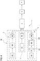
- Illustrated in the drawings by way of example are seven types of filter 2 (or portions 400 of rod 4) obtainable with corresponding machine operating configurations, from a first to a seventh operating configuration, respectively.
- the feed lines 7, 8, 9 (which are enabled) are active simultaneously and operate in parallel to provide the same garniture tongue 3 with the respective materials making up the rod 4.
- the control unit of the machine 1 is configured to control and coordinate the feeding of the materials (paper strip, stream of processed and shaped tow and groups of filter plugs) to the garniture tongue by the first, second and third feed lines 7, 8, 9, respectively.
- the control unit is also connected to the cutting station 5 and to the outfeed station 6, so that the cutting and outfeed steps are also automatically coordinated (through the control unit) by the first, second and third feed lines 7, 8, 9, respectively.
- a cylindrical core is placed in a position coaxial with the axis 302 of the garniture tongue 3.
- the numeral 201 denotes a tubular body of tow; the tubular body 201 of tow preferably extends the full length of the filter and is coaxial with a longitudinal axis of the filter 2.
- the tubular body 201 of tow has a transverse cross section which preferably has the shape of a circular crown.
- the tubular body 201 of tow is formed by folding the ribbon 813.
- the tubular body 201 has a joining zone located along a generator of the tubular body, in which opposite edges of a layer of tow folded into the shape of tube are joined together.
- the joining zone extends along a surface which is preferably oblique to a radial plane intersecting the joining zone itself.
- the filter 2 may comprise a wrapping 202 made from the paper strip 702 and, where present, placed coaxially with the longitudinal axis of the filter 2 in the outermost position (for example, in contact with an outside surface of the tubular body 201 of tow).
- the numeral 203 denotes filter plugs.
- the numeral 204 denotes a cylindrical body of tow.
- the filter plugs 203 may be positioned inside the tubular body 201 of tow in order to fill it entirely or partly (where part of the passage defined inside the tubular body 201 of tow may remain empty, while the remaining part is filled by filter plugs 203 or by a cylindrical portion of tow, that is a cylindrical body 204 of tow).
- the cylindrical body 204 of tow preferably extends the full length of the filter and is coaxial with a longitudinal axis of the filter 2.
- the cylindrical body 204 of tow might be present in the filter 2 instead of the filter plugs 203 or instead of the tubular body 201 of tow.
- the filter 2 might also comprise a completely hollow tubular body 201 of tow to define a passage from an inlet to an outlet of the tubular body 201 itself.
- the present disclosure provides a filter for cigarettes 2, realized (produced) by means of a machine 1 for the production of filters, wherein the machine 1 has one or more of the features described in the present disclosure.
- the present disclosure provides a filter for cigarettes 2, made according to a method for the production of filters, wherein said method has one or more of the features (or phases) described in the present disclosure.
- the filter 2 comprises a tubular body 201 of Tow, elongated along a longitudinal axis and having a cross section of a circular crown.
- said tubular body 201 has a junction area arranged along a generatrix of the tubular body, wherein opposite edges of a layer of Tow folded into a tube (i.e. said tubular body) are joined together.
- overlapping edges of the Tow layer lie on a junction surface which is inclined with respect to a radial plane passing through the longitudinal axis of the tubular body 201 of Tow.
- the filter 2 comprises a layer of paper positioned externally to the tubular body 201 and into contact therein.
- the filter 2 comprises a plurality of filter sections 203 of cylindrical shape, positioned inside the tubular body 201 and aligned in sequence along the longitudinal axis.
- the tubular body 201 is internally empty, at least in part.
- the tubular body 201 is internally empty (entirely), thus defining a through hole 205.
- the tubular body 201 internally has one or more filter sections 203 and one or more empty spaces (such empty spaces can be placed between two subsequent filter sections 203, and / or can be positioned at one or more of the two opposite ends of the filter).
Landscapes
- Cigarettes, Filters, And Manufacturing Of Filters (AREA)
Applications Claiming Priority (1)
| Application Number | Priority Date | Filing Date | Title |
|---|---|---|---|
| ITUA2016A001917A ITUA20161917A1 (it) | 2016-03-24 | 2016-03-24 | Macchina e metodo per la produzione di filtri per sigarette. |
Publications (2)
| Publication Number | Publication Date |
|---|---|
| EP3222158A1 true EP3222158A1 (fr) | 2017-09-27 |
| EP3222158B1 EP3222158B1 (fr) | 2019-05-08 |
Family
ID=56296909
Family Applications (1)
| Application Number | Title | Priority Date | Filing Date |
|---|---|---|---|
| EP17162760.7A Active EP3222158B1 (fr) | 2016-03-24 | 2017-03-24 | Machine et procédé de fabrication de filtres de cigarette |
Country Status (2)
| Country | Link |
|---|---|
| EP (1) | EP3222158B1 (fr) |
| IT (1) | ITUA20161917A1 (fr) |
Cited By (1)
| Publication number | Priority date | Publication date | Assignee | Title |
|---|---|---|---|---|
| IT202000014095A1 (it) * | 2020-06-12 | 2021-12-12 | Montrade S P A | Metodo per la realizzazione di un prodotto da fumo, macchina per la realizzazione di un prodotto da fumo e uso di tale macchina ed un articolo da fumo così ottenuto |
Citations (15)
| Publication number | Priority date | Publication date | Assignee | Title |
|---|---|---|---|---|
| US3242925A (en) * | 1960-02-15 | 1966-03-29 | Thomas A Sterne | Cigarette manufacture |
| US4064791A (en) * | 1975-11-06 | 1977-12-27 | American Filtrona Corporation | Method and apparatus for making tobacco smoke filter |
| US5209249A (en) | 1988-07-28 | 1993-05-11 | G. D. Societa Per Azioni | Cigarette checking apparatus |
| EP0638248A1 (fr) * | 1993-08-12 | 1995-02-15 | Philip Morris Products Inc. | Procédé et appareil de fabrication de filtres concentriques composés de deux ou plusieurs matériaux |
| EP1787534A1 (fr) | 2005-11-16 | 2007-05-23 | G.D. Societa' per Azioni | Machine pour la production de filtres composites |
| US20080302373A1 (en) * | 2007-06-11 | 2008-12-11 | R.J. Reynolds Tobacco Company | Apparatus for Inserting Objects into a Filter Component of a Smoking Article, and Associated Method |
| EP2145551A2 (fr) | 2008-07-18 | 2010-01-20 | G.D Societa' per Azioni | Machine de fabrication pour la production d'article de l'industrie du tabac |
| EP2591686A2 (fr) * | 2011-11-09 | 2013-05-15 | HAUNI Maschinenbau AG | Machine de fabrication de filtre de l'industrie de traitement du tabac |
| EP2633769A1 (fr) * | 2012-02-29 | 2013-09-04 | Aiger Group AG | Machine de fabrication de filtre de cigarette |
| EP2692249A1 (fr) * | 2011-03-31 | 2014-02-05 | Japan Tobacco, Inc. | Dispositif de fabrication de filtre, procédé de fabrication de filtre qui utilise ce dernier et filtre creux |
| WO2014068295A1 (fr) * | 2012-10-31 | 2014-05-08 | British American Tobacco (Investments) Limited | Filtre pour article à fumer |
| WO2014188318A1 (fr) * | 2013-05-22 | 2014-11-27 | G. D S.P.A. | Appareil destiné à la fabrication d'articles pour fumeur |
| WO2014198815A1 (fr) * | 2013-06-13 | 2014-12-18 | Essentra Filter Products Development Co. Pte. Ltd | Filtre pour la fumée de tabac |
| US8992400B2 (en) | 2010-07-08 | 2015-03-31 | G.D S.P.A. | Machine and method for manufacturing composite filters |
| WO2015044848A1 (fr) | 2013-09-26 | 2015-04-02 | G.D S.P.A. | Machine pour la fabrication de filtres composites |
-
2016
- 2016-03-24 IT ITUA2016A001917A patent/ITUA20161917A1/it unknown
-
2017
- 2017-03-24 EP EP17162760.7A patent/EP3222158B1/fr active Active
Patent Citations (15)
| Publication number | Priority date | Publication date | Assignee | Title |
|---|---|---|---|---|
| US3242925A (en) * | 1960-02-15 | 1966-03-29 | Thomas A Sterne | Cigarette manufacture |
| US4064791A (en) * | 1975-11-06 | 1977-12-27 | American Filtrona Corporation | Method and apparatus for making tobacco smoke filter |
| US5209249A (en) | 1988-07-28 | 1993-05-11 | G. D. Societa Per Azioni | Cigarette checking apparatus |
| EP0638248A1 (fr) * | 1993-08-12 | 1995-02-15 | Philip Morris Products Inc. | Procédé et appareil de fabrication de filtres concentriques composés de deux ou plusieurs matériaux |
| EP1787534A1 (fr) | 2005-11-16 | 2007-05-23 | G.D. Societa' per Azioni | Machine pour la production de filtres composites |
| US20080302373A1 (en) * | 2007-06-11 | 2008-12-11 | R.J. Reynolds Tobacco Company | Apparatus for Inserting Objects into a Filter Component of a Smoking Article, and Associated Method |
| EP2145551A2 (fr) | 2008-07-18 | 2010-01-20 | G.D Societa' per Azioni | Machine de fabrication pour la production d'article de l'industrie du tabac |
| US8992400B2 (en) | 2010-07-08 | 2015-03-31 | G.D S.P.A. | Machine and method for manufacturing composite filters |
| EP2692249A1 (fr) * | 2011-03-31 | 2014-02-05 | Japan Tobacco, Inc. | Dispositif de fabrication de filtre, procédé de fabrication de filtre qui utilise ce dernier et filtre creux |
| EP2591686A2 (fr) * | 2011-11-09 | 2013-05-15 | HAUNI Maschinenbau AG | Machine de fabrication de filtre de l'industrie de traitement du tabac |
| EP2633769A1 (fr) * | 2012-02-29 | 2013-09-04 | Aiger Group AG | Machine de fabrication de filtre de cigarette |
| WO2014068295A1 (fr) * | 2012-10-31 | 2014-05-08 | British American Tobacco (Investments) Limited | Filtre pour article à fumer |
| WO2014188318A1 (fr) * | 2013-05-22 | 2014-11-27 | G. D S.P.A. | Appareil destiné à la fabrication d'articles pour fumeur |
| WO2014198815A1 (fr) * | 2013-06-13 | 2014-12-18 | Essentra Filter Products Development Co. Pte. Ltd | Filtre pour la fumée de tabac |
| WO2015044848A1 (fr) | 2013-09-26 | 2015-04-02 | G.D S.P.A. | Machine pour la fabrication de filtres composites |
Cited By (1)
| Publication number | Priority date | Publication date | Assignee | Title |
|---|---|---|---|---|
| IT202000014095A1 (it) * | 2020-06-12 | 2021-12-12 | Montrade S P A | Metodo per la realizzazione di un prodotto da fumo, macchina per la realizzazione di un prodotto da fumo e uso di tale macchina ed un articolo da fumo così ottenuto |
Also Published As
| Publication number | Publication date |
|---|---|
| EP3222158B1 (fr) | 2019-05-08 |
| ITUA20161917A1 (it) | 2017-09-24 |
Similar Documents
| Publication | Publication Date | Title |
|---|---|---|
| EP2416673B1 (fr) | Introduction d'objets dans des articles alongés du tabac | |
| KR102569141B1 (ko) | 담배 가공 산업의 이중층 튜브 및 그 튜브의 제조 방법 | |
| EP3469923B1 (fr) | Machine de fabrication d'articles de tabac en forme de tige | |
| CN104754963B (zh) | 用于生产香烟的装配机以及相关装配方法 | |
| CN104768404B (zh) | 香烟制造组装机以及相关的组装方法 | |
| EP3897240A1 (fr) | Machine de fabrication de segments tubulaires de l'industrie du tabac | |
| CN104041938A (zh) | 用于组装诸如烟草制品的多段式筒状制品的方法和设备 | |
| GB2260887A (en) | Cigarettes with inserts | |
| EP3222158B1 (fr) | Machine et procédé de fabrication de filtres de cigarette | |
| CN106998792A (zh) | 吸烟制品组装机及制作吸烟制品的方法 | |
| US8142598B2 (en) | Filter tube making | |
| KR20170123689A (ko) | 흡연용품 래퍼 | |
| CN115884868A (zh) | 用于制造包括具有间隔和/或过滤功能的填充物的连续管状元件的机器和方法 | |
| CN104585878A (zh) | 用于制造过滤嘴条的装置和烟草加工行业的机器 | |
| JPH04352862A (ja) | たばこフィルター用繊維棒状体及びその製造装置 | |
| CN113615867B (zh) | 制造用于形成吸烟者制品的一部分的半成品的设备和方法 | |
| EP3639680B1 (fr) | Ligne de production et procédé de production d'articles en forme de tige de l'industrie du tabac | |
| WO2020194232A1 (fr) | Procédé et machine de fabrication d'une sous-unité d'un article à fumer | |
| WO2022029561A1 (fr) | Procédé et machine de fabrication d'une sous-unité d'un article à fumer | |
| WO2014188319A1 (fr) | Appareil pour fabriquer des articles de fumeurs | |
| KR20230011962A (ko) | 막대형 용품을 위한 크림핑된 충전재의 롤을 제조하기 위한 장치 및 방법 | |
| EP4417068A1 (fr) | Appareil de pliage pour plier un boudin de matériau de remplissage placé dans une tige continue de l'industrie du tabac | |
| WO2024153942A1 (fr) | Procédés et ensembles pour la fabrication d'un composant creux destiné à être utilisé dans ou avec un système de fourniture d'aérosol | |
| WO2024028596A2 (fr) | Appareil de fabrication d'un composant destiné à être utilisé dans un système de distribution | |
| JP2022507374A (ja) | 添加剤集合体 |
Legal Events
| Date | Code | Title | Description |
|---|---|---|---|
| PUAI | Public reference made under article 153(3) epc to a published international application that has entered the european phase |
Free format text: ORIGINAL CODE: 0009012 |
|
| STAA | Information on the status of an ep patent application or granted ep patent |
Free format text: STATUS: THE APPLICATION HAS BEEN PUBLISHED |
|
| AK | Designated contracting states |
Kind code of ref document: A1 Designated state(s): AL AT BE BG CH CY CZ DE DK EE ES FI FR GB GR HR HU IE IS IT LI LT LU LV MC MK MT NL NO PL PT RO RS SE SI SK SM TR |
|
| AX | Request for extension of the european patent |
Extension state: BA ME |
|
| STAA | Information on the status of an ep patent application or granted ep patent |
Free format text: STATUS: REQUEST FOR EXAMINATION WAS MADE |
|
| 17P | Request for examination filed |
Effective date: 20180327 |
|
| RBV | Designated contracting states (corrected) |
Designated state(s): AL AT BE BG CH CY CZ DE DK EE ES FI FR GB GR HR HU IE IS IT LI LT LU LV MC MK MT NL NO PL PT RO RS SE SI SK SM TR |
|
| GRAJ | Information related to disapproval of communication of intention to grant by the applicant or resumption of examination proceedings by the epo deleted |
Free format text: ORIGINAL CODE: EPIDOSDIGR1 |
|
| GRAP | Despatch of communication of intention to grant a patent |
Free format text: ORIGINAL CODE: EPIDOSNIGR1 |
|
| RIC1 | Information provided on ipc code assigned before grant |
Ipc: A24D 3/04 20060101ALI20181220BHEP Ipc: A24D 3/02 20060101AFI20181220BHEP |
|
| GRAP | Despatch of communication of intention to grant a patent |
Free format text: ORIGINAL CODE: EPIDOSNIGR1 |
|
| STAA | Information on the status of an ep patent application or granted ep patent |
Free format text: STATUS: GRANT OF PATENT IS INTENDED |
|
| INTG | Intention to grant announced |
Effective date: 20190205 |
|
| GRAS | Grant fee paid |
Free format text: ORIGINAL CODE: EPIDOSNIGR3 |
|
| GRAA | (expected) grant |
Free format text: ORIGINAL CODE: 0009210 |
|
| STAA | Information on the status of an ep patent application or granted ep patent |
Free format text: STATUS: THE PATENT HAS BEEN GRANTED |
|
| AK | Designated contracting states |
Kind code of ref document: B1 Designated state(s): AL AT BE BG CH CY CZ DE DK EE ES FI FR GB GR HR HU IE IS IT LI LT LU LV MC MK MT NL NO PL PT RO RS SE SI SK SM TR |
|
| REG | Reference to a national code |
Ref country code: GB Ref legal event code: FG4D |
|
| REG | Reference to a national code |
Ref country code: CH Ref legal event code: EP Ref country code: AT Ref legal event code: REF Ref document number: 1128787 Country of ref document: AT Kind code of ref document: T Effective date: 20190515 |
|
| REG | Reference to a national code |
Ref country code: DE Ref legal event code: R096 Ref document number: 602017003757 Country of ref document: DE Ref country code: IE Ref legal event code: FG4D |
|
| REG | Reference to a national code |
Ref country code: NL Ref legal event code: FP |
|
| REG | Reference to a national code |
Ref country code: LT Ref legal event code: MG4D |
|
| PG25 | Lapsed in a contracting state [announced via postgrant information from national office to epo] |
Ref country code: SE Free format text: LAPSE BECAUSE OF FAILURE TO SUBMIT A TRANSLATION OF THE DESCRIPTION OR TO PAY THE FEE WITHIN THE PRESCRIBED TIME-LIMIT Effective date: 20190508 Ref country code: PT Free format text: LAPSE BECAUSE OF FAILURE TO SUBMIT A TRANSLATION OF THE DESCRIPTION OR TO PAY THE FEE WITHIN THE PRESCRIBED TIME-LIMIT Effective date: 20190908 Ref country code: FI Free format text: LAPSE BECAUSE OF FAILURE TO SUBMIT A TRANSLATION OF THE DESCRIPTION OR TO PAY THE FEE WITHIN THE PRESCRIBED TIME-LIMIT Effective date: 20190508 Ref country code: NO Free format text: LAPSE BECAUSE OF FAILURE TO SUBMIT A TRANSLATION OF THE DESCRIPTION OR TO PAY THE FEE WITHIN THE PRESCRIBED TIME-LIMIT Effective date: 20190808 Ref country code: AL Free format text: LAPSE BECAUSE OF FAILURE TO SUBMIT A TRANSLATION OF THE DESCRIPTION OR TO PAY THE FEE WITHIN THE PRESCRIBED TIME-LIMIT Effective date: 20190508 Ref country code: LT Free format text: LAPSE BECAUSE OF FAILURE TO SUBMIT A TRANSLATION OF THE DESCRIPTION OR TO PAY THE FEE WITHIN THE PRESCRIBED TIME-LIMIT Effective date: 20190508 Ref country code: HR Free format text: LAPSE BECAUSE OF FAILURE TO SUBMIT A TRANSLATION OF THE DESCRIPTION OR TO PAY THE FEE WITHIN THE PRESCRIBED TIME-LIMIT Effective date: 20190508 |
|
| PG25 | Lapsed in a contracting state [announced via postgrant information from national office to epo] |
Ref country code: LV Free format text: LAPSE BECAUSE OF FAILURE TO SUBMIT A TRANSLATION OF THE DESCRIPTION OR TO PAY THE FEE WITHIN THE PRESCRIBED TIME-LIMIT Effective date: 20190508 Ref country code: RS Free format text: LAPSE BECAUSE OF FAILURE TO SUBMIT A TRANSLATION OF THE DESCRIPTION OR TO PAY THE FEE WITHIN THE PRESCRIBED TIME-LIMIT Effective date: 20190508 Ref country code: BG Free format text: LAPSE BECAUSE OF FAILURE TO SUBMIT A TRANSLATION OF THE DESCRIPTION OR TO PAY THE FEE WITHIN THE PRESCRIBED TIME-LIMIT Effective date: 20190808 Ref country code: GR Free format text: LAPSE BECAUSE OF FAILURE TO SUBMIT A TRANSLATION OF THE DESCRIPTION OR TO PAY THE FEE WITHIN THE PRESCRIBED TIME-LIMIT Effective date: 20190809 |
|
| REG | Reference to a national code |
Ref country code: AT Ref legal event code: MK05 Ref document number: 1128787 Country of ref document: AT Kind code of ref document: T Effective date: 20190508 |
|
| PG25 | Lapsed in a contracting state [announced via postgrant information from national office to epo] |
Ref country code: DK Free format text: LAPSE BECAUSE OF FAILURE TO SUBMIT A TRANSLATION OF THE DESCRIPTION OR TO PAY THE FEE WITHIN THE PRESCRIBED TIME-LIMIT Effective date: 20190508 Ref country code: AT Free format text: LAPSE BECAUSE OF FAILURE TO SUBMIT A TRANSLATION OF THE DESCRIPTION OR TO PAY THE FEE WITHIN THE PRESCRIBED TIME-LIMIT Effective date: 20190508 Ref country code: EE Free format text: LAPSE BECAUSE OF FAILURE TO SUBMIT A TRANSLATION OF THE DESCRIPTION OR TO PAY THE FEE WITHIN THE PRESCRIBED TIME-LIMIT Effective date: 20190508 Ref country code: SK Free format text: LAPSE BECAUSE OF FAILURE TO SUBMIT A TRANSLATION OF THE DESCRIPTION OR TO PAY THE FEE WITHIN THE PRESCRIBED TIME-LIMIT Effective date: 20190508 Ref country code: RO Free format text: LAPSE BECAUSE OF FAILURE TO SUBMIT A TRANSLATION OF THE DESCRIPTION OR TO PAY THE FEE WITHIN THE PRESCRIBED TIME-LIMIT Effective date: 20190508 Ref country code: CZ Free format text: LAPSE BECAUSE OF FAILURE TO SUBMIT A TRANSLATION OF THE DESCRIPTION OR TO PAY THE FEE WITHIN THE PRESCRIBED TIME-LIMIT Effective date: 20190508 |
|
| REG | Reference to a national code |
Ref country code: DE Ref legal event code: R097 Ref document number: 602017003757 Country of ref document: DE |
|
| PG25 | Lapsed in a contracting state [announced via postgrant information from national office to epo] |
Ref country code: SM Free format text: LAPSE BECAUSE OF FAILURE TO SUBMIT A TRANSLATION OF THE DESCRIPTION OR TO PAY THE FEE WITHIN THE PRESCRIBED TIME-LIMIT Effective date: 20190508 Ref country code: IT Free format text: LAPSE BECAUSE OF FAILURE TO SUBMIT A TRANSLATION OF THE DESCRIPTION OR TO PAY THE FEE WITHIN THE PRESCRIBED TIME-LIMIT Effective date: 20190508 |
|
| PLBE | No opposition filed within time limit |
Free format text: ORIGINAL CODE: 0009261 |
|
| STAA | Information on the status of an ep patent application or granted ep patent |
Free format text: STATUS: NO OPPOSITION FILED WITHIN TIME LIMIT |
|
| PG25 | Lapsed in a contracting state [announced via postgrant information from national office to epo] |
Ref country code: TR Free format text: LAPSE BECAUSE OF FAILURE TO SUBMIT A TRANSLATION OF THE DESCRIPTION OR TO PAY THE FEE WITHIN THE PRESCRIBED TIME-LIMIT Effective date: 20190508 |
|
| 26N | No opposition filed |
Effective date: 20200211 |
|
| PG25 | Lapsed in a contracting state [announced via postgrant information from national office to epo] |
Ref country code: PL Free format text: LAPSE BECAUSE OF FAILURE TO SUBMIT A TRANSLATION OF THE DESCRIPTION OR TO PAY THE FEE WITHIN THE PRESCRIBED TIME-LIMIT Effective date: 20190508 |
|
| PGFP | Annual fee paid to national office [announced via postgrant information from national office to epo] |
Ref country code: NL Payment date: 20200326 Year of fee payment: 4 Ref country code: DE Payment date: 20200327 Year of fee payment: 4 |
|
| PG25 | Lapsed in a contracting state [announced via postgrant information from national office to epo] |
Ref country code: SI Free format text: LAPSE BECAUSE OF FAILURE TO SUBMIT A TRANSLATION OF THE DESCRIPTION OR TO PAY THE FEE WITHIN THE PRESCRIBED TIME-LIMIT Effective date: 20190508 |
|
| PG25 | Lapsed in a contracting state [announced via postgrant information from national office to epo] |
Ref country code: MC Free format text: LAPSE BECAUSE OF FAILURE TO SUBMIT A TRANSLATION OF THE DESCRIPTION OR TO PAY THE FEE WITHIN THE PRESCRIBED TIME-LIMIT Effective date: 20190508 Ref country code: ES Free format text: LAPSE BECAUSE OF FAILURE TO SUBMIT A TRANSLATION OF THE DESCRIPTION OR TO PAY THE FEE WITHIN THE PRESCRIBED TIME-LIMIT Effective date: 20190508 |
|
| REG | Reference to a national code |
Ref country code: CH Ref legal event code: PL |
|
| REG | Reference to a national code |
Ref country code: BE Ref legal event code: MM Effective date: 20200331 |
|
| PG25 | Lapsed in a contracting state [announced via postgrant information from national office to epo] |
Ref country code: LU Free format text: LAPSE BECAUSE OF NON-PAYMENT OF DUE FEES Effective date: 20200324 |
|
| PG25 | Lapsed in a contracting state [announced via postgrant information from national office to epo] |
Ref country code: IE Free format text: LAPSE BECAUSE OF NON-PAYMENT OF DUE FEES Effective date: 20200324 Ref country code: FR Free format text: LAPSE BECAUSE OF NON-PAYMENT OF DUE FEES Effective date: 20200331 Ref country code: CH Free format text: LAPSE BECAUSE OF NON-PAYMENT OF DUE FEES Effective date: 20200331 Ref country code: LI Free format text: LAPSE BECAUSE OF NON-PAYMENT OF DUE FEES Effective date: 20200331 |
|
| PG25 | Lapsed in a contracting state [announced via postgrant information from national office to epo] |
Ref country code: BE Free format text: LAPSE BECAUSE OF NON-PAYMENT OF DUE FEES Effective date: 20200331 |
|
| REG | Reference to a national code |
Ref country code: DE Ref legal event code: R119 Ref document number: 602017003757 Country of ref document: DE |
|
| REG | Reference to a national code |
Ref country code: NL Ref legal event code: MM Effective date: 20210401 |
|
| GBPC | Gb: european patent ceased through non-payment of renewal fee |
Effective date: 20210324 |
|
| PG25 | Lapsed in a contracting state [announced via postgrant information from national office to epo] |
Ref country code: DE Free format text: LAPSE BECAUSE OF NON-PAYMENT OF DUE FEES Effective date: 20211001 Ref country code: NL Free format text: LAPSE BECAUSE OF NON-PAYMENT OF DUE FEES Effective date: 20210401 Ref country code: GB Free format text: LAPSE BECAUSE OF NON-PAYMENT OF DUE FEES Effective date: 20210324 |
|
| PG25 | Lapsed in a contracting state [announced via postgrant information from national office to epo] |
Ref country code: MT Free format text: LAPSE BECAUSE OF FAILURE TO SUBMIT A TRANSLATION OF THE DESCRIPTION OR TO PAY THE FEE WITHIN THE PRESCRIBED TIME-LIMIT Effective date: 20190508 Ref country code: CY Free format text: LAPSE BECAUSE OF FAILURE TO SUBMIT A TRANSLATION OF THE DESCRIPTION OR TO PAY THE FEE WITHIN THE PRESCRIBED TIME-LIMIT Effective date: 20190508 |
|
| PG25 | Lapsed in a contracting state [announced via postgrant information from national office to epo] |
Ref country code: MK Free format text: LAPSE BECAUSE OF FAILURE TO SUBMIT A TRANSLATION OF THE DESCRIPTION OR TO PAY THE FEE WITHIN THE PRESCRIBED TIME-LIMIT Effective date: 20190508 Ref country code: IS Free format text: LAPSE BECAUSE OF FAILURE TO SUBMIT A TRANSLATION OF THE DESCRIPTION OR TO PAY THE FEE WITHIN THE PRESCRIBED TIME-LIMIT Effective date: 20190908 |