EP3221745B1 - Stützring zur montage eines weichen kastens an einer lichtquelle - Google Patents
Stützring zur montage eines weichen kastens an einer lichtquelle Download PDFInfo
- Publication number
- EP3221745B1 EP3221745B1 EP15860087.4A EP15860087A EP3221745B1 EP 3221745 B1 EP3221745 B1 EP 3221745B1 EP 15860087 A EP15860087 A EP 15860087A EP 3221745 B1 EP3221745 B1 EP 3221745B1
- Authority
- EP
- European Patent Office
- Prior art keywords
- cavity
- support
- support ring
- ring
- light source
- Prior art date
- Legal status (The legal status is an assumption and is not a legal conclusion. Google has not performed a legal analysis and makes no representation as to the accuracy of the status listed.)
- Active
Links
Images
Classifications
-
- F—MECHANICAL ENGINEERING; LIGHTING; HEATING; WEAPONS; BLASTING
- F21—LIGHTING
- F21V—FUNCTIONAL FEATURES OR DETAILS OF LIGHTING DEVICES OR SYSTEMS THEREOF; STRUCTURAL COMBINATIONS OF LIGHTING DEVICES WITH OTHER ARTICLES, NOT OTHERWISE PROVIDED FOR
- F21V17/00—Fastening of component parts of lighting devices, e.g. shades, globes, refractors, reflectors, filters, screens, grids or protective cages
- F21V17/10—Fastening of component parts of lighting devices, e.g. shades, globes, refractors, reflectors, filters, screens, grids or protective cages characterised by specific fastening means or way of fastening
-
- G—PHYSICS
- G03—PHOTOGRAPHY; CINEMATOGRAPHY; ANALOGOUS TECHNIQUES USING WAVES OTHER THAN OPTICAL WAVES; ELECTROGRAPHY; HOLOGRAPHY
- G03B—APPARATUS OR ARRANGEMENTS FOR TAKING PHOTOGRAPHS OR FOR PROJECTING OR VIEWING THEM; APPARATUS OR ARRANGEMENTS EMPLOYING ANALOGOUS TECHNIQUES USING WAVES OTHER THAN OPTICAL WAVES; ACCESSORIES THEREFOR
- G03B15/00—Special procedures for taking photographs; Apparatus therefor
- G03B15/02—Illuminating scene
- G03B15/06—Special arrangements of screening, diffusing, or reflecting devices, e.g. in studio
-
- F—MECHANICAL ENGINEERING; LIGHTING; HEATING; WEAPONS; BLASTING
- F16—ENGINEERING ELEMENTS AND UNITS; GENERAL MEASURES FOR PRODUCING AND MAINTAINING EFFECTIVE FUNCTIONING OF MACHINES OR INSTALLATIONS; THERMAL INSULATION IN GENERAL
- F16M—FRAMES, CASINGS OR BEDS OF ENGINES, MACHINES OR APPARATUS, NOT SPECIFIC TO ENGINES, MACHINES OR APPARATUS PROVIDED FOR ELSEWHERE; STANDS; SUPPORTS
- F16M13/00—Other supports for positioning apparatus or articles; Means for steadying hand-held apparatus or articles
- F16M13/02—Other supports for positioning apparatus or articles; Means for steadying hand-held apparatus or articles for supporting on, or attaching to, an object, e.g. tree, gate, window-frame, cycle
Definitions
- the present disclosure relates to a support ring for mounting of a soft box on a light source.
- the disclosure also relates to a method for manufacturing a support ring for mounting of a soft box on a light source.
- a soft box is a type of photographic lighting device.
- a soft box creates an even and diffused light by directing light through some diffusing material, or by "bouncing" light off a second surface to diffuse the light.
- One type of bouncing source is an umbrella light where the light from the bulb is bounced off the inside of a metalized umbrella to create a soft indirect light.
- One type of soft box is an enclosure around a light source comprising reflective side and back walls and a diffusing material at the front of the light.
- a speed ring is a solid metal ring-shaped disk which is used to attach a soft box to a light source such as a studio strobe or a continuous light source. Often there are between 4 to 8 holes drilled into the circumference of the ring. These holes receive the support pins of the soft box. Support pins are then held in place in the holes by tension.
- the shape of the speed ring can vary depending on the manufacturer.
- the opening in the centre ranges from 4 to 7 inches, allowing the light source to enter the soft box or other light modifier.
- Soft boxes especially large soft boxes require a lot of manual effort during installation.
- the support pins must be manually bent and angled perpendicular to the centre axis of the speed ring in order to be able to be inserted in the hole of the speed ring.
- the force required increases with the number of metal ribs which have to be fitted.
- a concept involves providing a speed ring with an entry element arranged on a radial outside and arranged to counteract a force required to bend the support pin to an angle where the support pin can be inserted into the speed ring.
- the disclosure presents a support ring for mounting of a soft box on a light source.
- the support ring comprises attachment means for attachment of the support ring to the light source, at least one cavity configured to receive support pins of the soft box.
- the cavity further comprises a first and a second support element arranged to counteract a torque from the support pins, when the support pins are in an inserted position in the cavity, and at least one entry element arranged on a radial outside of the cavity and arranged to counteract a force required to bend the support pin to an angle where the support pin can be inserted into the cavity.
- the support ring With at least one entry element arranged on a radial outside of the cavity and arranged to counteract a force required to bend the support pin to an angle where the support pin can be inserted into the cavity, it becomes much easier to insert the support pin into the cavity since the entry element can counter force the support pin when the support pin is bent. Thus it is only required to pull the support pin in order to bend the support pin so that the support pin can be inserted into the cavity.
- the present disclosure also relates to embodiments of a method for manufacturing a support ring for mounting of a soft box on a light source.
- the method comprises providing the support ring with attachment means for attachment of the light source on the support ring.
- providing the cavity with at least one entry element arranged on a radial outside of the cavity and arranged to counteract a force required to bend the support pin to an angle where the support pin can be inserted into the cavity.
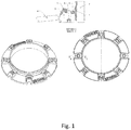
- Figure 1 schematically illustrates a speed ring according to an exemplary embodiment of the present disclosure.
- Figure 1 schematically illustrates a support ring 1 for mounting of a soft box on a light source.
- the support ring 1 comprises attachment means 2 for attachment of the support ring 1 to the light source.
- the support ring comprises at least one cavity 3 configured to receive support pins 4 of the soft box.
- the cavity 3 further comprises a first 5 and a second 6 support element arranged to counteract a torque from the support pins, when the support pins are in an inserted position in the cavity; and at least one entry element 7 arranged on a radial outside of the cavity 3 and arranged to counteract a force required to bend the support pin to an angle where the support pin can be inserted into the cavity 3.
- the at least one cavity 3 can also be a space 3 that among others is narrowed by the first 5 and the second 6 support elements.
- the support ring 1 By providing the support ring 1 with at least one entry element 7 arranged on a radial outside of the cavity 3 and arranged to counteract a force required to bend the support pin to an angle where the support pin can be inserted into the cavity 3, it becomes much easier to insert the support pin 4 into the cavity 3 since the entry element 7 can counter the force from the support pin 4 when the support pin 4 is bent. Thus it is only required to pull the support pin 4 in order to bend the support pin 4 so that the support pin 4 can be inserted into the cavity 3.
- the support ring 1 can be manufactured in many different materials.
- the support ring 1 is made of cast aluminium.
- An advantage with manufacturing the support ring 1 in cast aluminium is that the manufacturing process is easy which means that the support ring 1 can be produced at a low cost.
- Another advantage by manufacturing the support ring 1 in aluminium is that the support ring 1 becomes strong and light weight.
- the cavity 3 in the support ring 1 may be embodied in many different ways. It is however important that the cavity has at least the first 5 and the second 6 support element arranged to counteract a torque from the support pins 4, when the support pins 4 are in an inserted position in the cavity 3.
- the first 5 and the second 6 support elements are inner wall sections of the cylinder 3.
- the cross section of the cavity 3 perpendicular to the radial direction is rectangular or quadratic.
- the dimension of the cross section is adapted to fit the diameter of the support pins 4.
- the first 5 and the second 6 support elements can be interval sections of the quadratic cavity 3.
- first 5 and the second 6 support elements are bar elements perpendicular to a radial direction of the cavity 3.
- the first 5 and the second 6 support elements can be bar elements perpendicular to a radial direction of the cavity 3 in exemplary embodiments were the cavity 3 has different shape.
- the cavity 3 does not have to be a closed space.
- An advantage with the cavity 3 not being a closed space is that the weight of the support ring 1 can be reduced.
- first 5 and the second 6 support elements are bar elements 5, 6, the cross section of the cavity is rectangular or quadratic. In another exemplary embodiment were the first 5 and the second 6 support elements are the bar elements 5, 6 the cross section of the cavity is cylinder shaped.
- the at least one entry element 7 may be embodied in many different ways.
- the at least one entry element 7 is an outer edge of the cavity 3.
- An advantage with this embodiment is that it is not necessary to bend the support pin as much before the outer edge 7 can counteract the force, since the outer edge 7 is positioned further away from the centre of the support ring than the other edge of the cavity.
- the outer edge of the cavity can be embodied in many different ways. It is however important that the outer edge can counteract a force required bending the support pin to an angle where the support pin can be inserted into the cavity 3.
- the at least one entry element 7 is an element arranged at the radial outer opening of the cavity 3.
- This element can be embodied in many different ways. It is however important that the element can counteract a force required bending the support pin to an angle where the support pin can be inserted into the cavity 3.
- the present disclosure also relates to a method for manufacturing a support ring 1 for mounting of a soft box on a light source.
- the method comprises a first step of providing the support ring 1 with attachment means 2 for attachment of the light source on the support ring 1.
- the support ring 1 is provided with at least one cavity 3 configured to receive support pins 4 of the soft box.
- the cavity 3 is provided with a first 5 and a second 6 support element arranged to counteract a torque from the support pins, when the support pins are in an inserted position in the cavity 3.
- the cavity 3 is provided with at least one entry element 7 arranged on a radial outside of the cavity 3 and arranged to counteract a force required to bend the support pin to an angle where the support pin can be inserted into the cavity 3.
- the method of manufacturing the speed ring 1 comprises manufacturing the speed ring wherein the cavity 3 is cylinder shaped and wherein the diameter of the cylinder is adapted to the diameter of the support pins 4.
- the speed ring can be manufactured so that the first 5 and the second 6 support elements are inner wall sections of the cylinder.
- a cross section of the cavity 3 perpendicular to the radial direction is rectangular or quadratic and the dimension of the radial intersection is adapted to fit the diameter of the support pins 4.
- the first 5 and the second 6 support elements are inner wall sections of the rectangular or quadratic cavity 3.
- the first 5 and the second 6 support elements are bar elements perpendicular to a radial direction of the cavity 3.
- the at least one entry element 7 is an outer edge of the cavity 3. In another embodiment of the method the at least one entry element 7 is an element arranged at the radial outer opening of the cavity 3.
- the steps can occur in another order than the order described.
- two method steps shown in succession can in fact be executed substantially concurrently or the method steps can sometimes be executed in the reverse order, depending upon the manufacturing method.
- the speed ring 1 is made of cast aluminium, the method steps are executed substantially concurrently.
Landscapes
- Engineering & Computer Science (AREA)
- General Engineering & Computer Science (AREA)
- Physics & Mathematics (AREA)
- General Physics & Mathematics (AREA)
- Mechanical Engineering (AREA)
- Non-Portable Lighting Devices Or Systems Thereof (AREA)
- Fastening Of Light Sources Or Lamp Holders (AREA)
Claims (16)
- Stützring (1) zum Montieren einer Softbox an einer Lichtquelle, wobei der Stützring (1) umfasst:Befestigungsmittel (2) zur Befestigung des Stützrings (1) an der Lichtquelle;mindestens eine Aussparung (3), die zur Aufnahme von Stützstiften (4) der Softbox ausgelegt ist, dadurch gekennzeichnet, dass die Aussparung (3) ferner umfasstein erstes (5) und ein zweites (6) Stützelement, die zum Entgegenwirken eines Moments der Stützstifte vorgesehen sind, wenn sich diese in einer eingesetzten Position in der Aussparung befinden; undmindestens ein Einführelement (7), das an einer radialen Außenseite der Aussparung (3) vorgesehen ist und ausgelegt ist, um einer Kraft entgegenzuwirken, die erforderlich ist, um den Stützstift in einen Winkel zu biegen, wo der Stützstift in die Aussparung (3) eingeführt werden kann.
- Stützring (1) nach Anspruch 1, wobei die Aussparung (3) zylinderförmig ist, und wobei der Durchmesser des Zylinders an den Durchmesser der Stützstifte (4) angepasst ist.
- Stützring (1) nach Anspruch 2, wobei das erste (5) und das zweite (6) Stützelement Innenwandabschnitte des Zylinders darstellen.
- Stützring (1) nach Anspruch 1, wobei ein zur Radialrichtung senkrechter Querschnitt der Aussparung (3) rechteckig oder quadratisch ist, und wobei die Abmessung des Querschnitts dazu angepasst ist, dem Durchmesser der Stützstifte (4) zu entsprechen.
- Stützring (1) nach Anspruch 4, wobei das erste (5) und das zweite (6) Stützelement Intervallabschnitte der rechteckigen oder quadratischen Aussparung (3) sind.
- Stützring (1) nach einem der Ansprüche 1 und 4, wobei das erste (5) und das zweite (6) Stützelement Balkenelemente sind, die zu einer Radialrichtung der Aussparung (3) senkrecht sind.
- Stützring (1) nach einem der Ansprüche 1 bis 6, wobei das mindestens eine Einführelement (7) Außenkante der Aussparung (3) ist.
- Stützring (1) nach einem der Ansprüche 1 bis 6, wobei das mindestens eine Einführelement (7) ein an der radial äußeren Öffnung der Aussparung (3) angeordnetes Element umfasst.
- Verfahren zur Herstellung eines Stützrings (1) zum Montieren einer Softbox an einer Lichtquelle, wobei das Verfahren umfasst:Versehen des Stützrings (1) mit Befestigungsmitteln (2) zur Befestigung der Lichtquelle an dem Stützring (1);Versehen des Stützrings (1) mit mindestens einer Aussparung (3), die zur Aufnahme von Stützstiften (4) der Softbox ausgelegt ist,Versehen der Aussparung (3) mit einem ersten (5) und einem zweiten (6) Stützelement, die zum Entgegenwirken eines Moments der Stützstifte vorgesehen sind, wenn sich diese in einer eingesetzten Position in der Aussparung befinden; undVersehen der Aussparung (3) mit mindestens einem Einführelement (7), das an einer radialen Außenseite der Aussparung (3) vorgesehen ist und ausgelegt ist, um einer Kraft entgegenzuwirken, die erforderlich ist, um den Stützstift in einen Winkel zu biegen, wo der Stützstift in die Aussparung (3) eingeführt werden kann.
- Verfahren nach Anspruch 9 wobei die Aussparung (3) zylinderförmig ist, und wobei der Durchmesser des Zylinders an den Durchmesser der Stützstifte (4) angepasst ist.
- Verfahren nach Anspruch 10, wobei das erste (5) und das zweite (6) Stützelement Innenwandabschnitte des Zylinders darstellen.
- Verfahren nach Anspruch 9, wobei ein zur Radialrichtung senkrechter Querschnitt der Aussparung (3) rechteckig oder quadratisch ist, und wobei die Abmessung des radialen Querschnitts dazu angepasst ist, dem Durchmesser der Stützstifte (4) zu entsprechen.
- Verfahren nach Anspruch 12, wobei das erste (5) und das zweite (6) Stützelement Innenwandabschnitte der rechteckigen oder quadratischen Aussparung (3) sind.
- Verfahren nach Anspruch 9 und 12, wobei das erste (5) und das zweite (6) Stützelement Balkenelemente sind, die zu einer Radialrichtung der Aussparung (3) senkrecht sind.
- Verfahren nach einem der Ansprüche 9 bis 14, wobei das mindestens eine Einführelement (7) Außenkante der Aussparung (3) ist.
- Verfahren nach einem der Ansprüche 9 bis 15, wobei das mindestens eine Einführelement (7) ein an der radial äußeren Öffnung der Aussparung (3) angeordnetes Element umfasst.
Applications Claiming Priority (2)
| Application Number | Priority Date | Filing Date | Title |
|---|---|---|---|
| SE1451392 | 2014-11-19 | ||
| PCT/SE2015/051140 WO2016080885A1 (en) | 2014-11-19 | 2015-10-28 | A support ring for mounting of a soft box on a light source |
Publications (3)
| Publication Number | Publication Date |
|---|---|
| EP3221745A1 EP3221745A1 (de) | 2017-09-27 |
| EP3221745A4 EP3221745A4 (de) | 2019-06-12 |
| EP3221745B1 true EP3221745B1 (de) | 2020-08-12 |
Family
ID=56014282
Family Applications (1)
| Application Number | Title | Priority Date | Filing Date |
|---|---|---|---|
| EP15860087.4A Active EP3221745B1 (de) | 2014-11-19 | 2015-10-28 | Stützring zur montage eines weichen kastens an einer lichtquelle |
Country Status (4)
| Country | Link |
|---|---|
| US (1) | US10197250B2 (de) |
| EP (1) | EP3221745B1 (de) |
| CN (1) | CN107003590B (de) |
| WO (1) | WO2016080885A1 (de) |
Family Cites Families (15)
| Publication number | Priority date | Publication date | Assignee | Title |
|---|---|---|---|---|
| US2948287A (en) | 1957-09-30 | 1960-08-09 | Charles W Moss | Quickly-erectable folding portable shelter |
| DE19910469A1 (de) * | 1999-03-10 | 2000-09-21 | Wila Leuchten Ag Sevelen | Leuchtenanordnung |
| US6651682B1 (en) | 2001-08-03 | 2003-11-25 | James Woodward | Rugged assemable, disassemable and storable umbrella |
| CN2621307Y (zh) * | 2002-09-13 | 2004-06-23 | 广东普思贸易有限公司 | 柔光箱接口 |
| US7077534B2 (en) * | 2004-04-02 | 2006-07-18 | Calumet Photographic Inc. | Soft box assembly and pole support assembly therefor |
| CN200956080Y (zh) * | 2006-10-12 | 2007-10-03 | 深圳市元科摄影器材有限公司 | 一种柔光箱转接盘 |
| CN200969013Y (zh) * | 2006-11-14 | 2007-10-31 | 何济仪 | 一种具有柔光箱的常亮型摄影灯 |
| US20070217772A1 (en) * | 2006-11-28 | 2007-09-20 | Lemelson Greg M | Integrated light head apparatus and methods of use thereof |
| US7416316B2 (en) | 2006-12-06 | 2008-08-26 | Lowel-Light Manufacturing, Inc. | Strut holding assembly |
| US8157226B2 (en) * | 2008-09-23 | 2012-04-17 | Paul Kent Peregrine | Mounting system for attaching multiple light sources for photographic use |
| US8684569B2 (en) * | 2011-07-06 | 2014-04-01 | Cree, Inc. | Lens and trim attachment structure for solid state downlights |
| KR101127458B1 (ko) * | 2011-10-20 | 2012-03-22 | 김종석 | 접이식 소프트박스 |
| TW201411035A (zh) * | 2012-09-14 | 2014-03-16 | Taiwan Fu Hsing Ind Co Ltd | 燈具的安裝結構 |
| US20140153277A1 (en) * | 2012-11-30 | 2014-06-05 | Liang Meng Plastic Share Co., Ltd. | Assembling structure for led lamp module |
| KR101478673B1 (ko) * | 2013-04-04 | 2015-01-02 | 김종석 | 소프트박스형 무선제어 조명장치 |
-
2015
- 2015-10-28 EP EP15860087.4A patent/EP3221745B1/de active Active
- 2015-10-28 US US15/525,542 patent/US10197250B2/en active Active
- 2015-10-28 CN CN201580060655.0A patent/CN107003590B/zh active Active
- 2015-10-28 WO PCT/SE2015/051140 patent/WO2016080885A1/en not_active Ceased
Non-Patent Citations (1)
| Title |
|---|
| None * |
Also Published As
| Publication number | Publication date |
|---|---|
| CN107003590B (zh) | 2019-10-01 |
| US20170314767A1 (en) | 2017-11-02 |
| EP3221745A1 (de) | 2017-09-27 |
| CN107003590A (zh) | 2017-08-01 |
| WO2016080885A1 (en) | 2016-05-26 |
| US10197250B2 (en) | 2019-02-05 |
| EP3221745A4 (de) | 2019-06-12 |
Similar Documents
| Publication | Publication Date | Title |
|---|---|---|
| JP2017020648A (ja) | 機器を取り付ける取付装置、及び取付方法、取外方法 | |
| US10520169B2 (en) | Snap in retrofit panel | |
| EP3418621B1 (de) | Beleuchtungsvorrichtung und verfahren zur herstellung einer beleuchtungsvorrichtung | |
| US10197250B2 (en) | Support ring for mounting of a soft box on a light source | |
| EP2902260A3 (de) | Öffnungsfähiges Dach für ein Fahrzeug und dazugehörige Rolloanordnung | |
| US20150148183A1 (en) | Planetary gearset | |
| RU195863U1 (ru) | Устройство для монтажа вспомогательного оборудования в натяжном потолке | |
| CN201666550U (zh) | 吊顶射灯与天花面板的组合连接装置 | |
| ITTO980102A1 (it) | Proiettore per autoveicoli | |
| US9239162B2 (en) | Liner for preventing airflow through a recessed light and a method for installing the liner | |
| US20080137352A1 (en) | Strut holding assembly | |
| CN103185308B (zh) | 灯具固定装置及具有所述灯具固定装置的灯具 | |
| CN108957908B (zh) | 一种双调节光圈 | |
| BR112017009874A2 (pt) | espelho de porta de veículo | |
| US20080083513A1 (en) | Dual-purpose fixing core for a blind | |
| CN104896073A (zh) | 减速器 | |
| RU139023U1 (ru) | Устройство для крепления светильника (варианты) | |
| US3476925A (en) | Floodlight reflector assembly | |
| JP7003557B2 (ja) | 照明器具 | |
| KR200450149Y1 (ko) | 회전 및 각도 조절이 가능한 다운라이트용 램프홀더 | |
| CN205174256U (zh) | 一种灯具 | |
| JP6799749B2 (ja) | 換気フード | |
| CN100510566C (zh) | 空气扩散器主体部的安装垂片的形成方法及空气扩散器主体部的安装垂片 | |
| CN204899735U (zh) | 一种组装式卷帘轨道以及窗帘 | |
| CN204403939U (zh) | 新型logo投影灯 |
Legal Events
| Date | Code | Title | Description |
|---|---|---|---|
| STAA | Information on the status of an ep patent application or granted ep patent |
Free format text: STATUS: THE INTERNATIONAL PUBLICATION HAS BEEN MADE |
|
| PUAI | Public reference made under article 153(3) epc to a published international application that has entered the european phase |
Free format text: ORIGINAL CODE: 0009012 |
|
| STAA | Information on the status of an ep patent application or granted ep patent |
Free format text: STATUS: REQUEST FOR EXAMINATION WAS MADE |
|
| 17P | Request for examination filed |
Effective date: 20170612 |
|
| AK | Designated contracting states |
Kind code of ref document: A1 Designated state(s): AL AT BE BG CH CY CZ DE DK EE ES FI FR GB GR HR HU IE IS IT LI LT LU LV MC MK MT NL NO PL PT RO RS SE SI SK SM TR |
|
| AX | Request for extension of the european patent |
Extension state: BA ME |
|
| DAV | Request for validation of the european patent (deleted) | ||
| DAX | Request for extension of the european patent (deleted) | ||
| A4 | Supplementary search report drawn up and despatched |
Effective date: 20190515 |
|
| RIC1 | Information provided on ipc code assigned before grant |
Ipc: F21V 7/18 20060101ALI20190509BHEP Ipc: F21V 17/04 20060101ALI20190509BHEP Ipc: F21V 1/06 20060101ALI20190509BHEP Ipc: G03B 15/02 20060101AFI20190509BHEP |
|
| REG | Reference to a national code |
Ref country code: DE Ref legal event code: R079 Ref document number: 602015057506 Country of ref document: DE Free format text: PREVIOUS MAIN CLASS: G03B0015020000 Ipc: G03B0015060000 |
|
| RIC1 | Information provided on ipc code assigned before grant |
Ipc: G03B 15/06 20060101AFI20200224BHEP |
|
| GRAP | Despatch of communication of intention to grant a patent |
Free format text: ORIGINAL CODE: EPIDOSNIGR1 |
|
| STAA | Information on the status of an ep patent application or granted ep patent |
Free format text: STATUS: GRANT OF PATENT IS INTENDED |
|
| INTG | Intention to grant announced |
Effective date: 20200504 |
|
| GRAS | Grant fee paid |
Free format text: ORIGINAL CODE: EPIDOSNIGR3 |
|
| GRAA | (expected) grant |
Free format text: ORIGINAL CODE: 0009210 |
|
| STAA | Information on the status of an ep patent application or granted ep patent |
Free format text: STATUS: THE PATENT HAS BEEN GRANTED |
|
| AK | Designated contracting states |
Kind code of ref document: B1 Designated state(s): AL AT BE BG CH CY CZ DE DK EE ES FI FR GB GR HR HU IE IS IT LI LT LU LV MC MK MT NL NO PL PT RO RS SE SI SK SM TR |
|
| REG | Reference to a national code |
Ref country code: CH Ref legal event code: EP |
|
| REG | Reference to a national code |
Ref country code: DE Ref legal event code: R096 Ref document number: 602015057506 Country of ref document: DE |
|
| REG | Reference to a national code |
Ref country code: IE Ref legal event code: FG4D |
|
| REG | Reference to a national code |
Ref country code: AT Ref legal event code: REF Ref document number: 1302143 Country of ref document: AT Kind code of ref document: T Effective date: 20200915 |
|
| REG | Reference to a national code |
Ref country code: LT Ref legal event code: MG4D |
|
| REG | Reference to a national code |
Ref country code: NL Ref legal event code: MP Effective date: 20200812 |
|
| PG25 | Lapsed in a contracting state [announced via postgrant information from national office to epo] |
Ref country code: SE Free format text: LAPSE BECAUSE OF FAILURE TO SUBMIT A TRANSLATION OF THE DESCRIPTION OR TO PAY THE FEE WITHIN THE PRESCRIBED TIME-LIMIT Effective date: 20200812 Ref country code: BG Free format text: LAPSE BECAUSE OF FAILURE TO SUBMIT A TRANSLATION OF THE DESCRIPTION OR TO PAY THE FEE WITHIN THE PRESCRIBED TIME-LIMIT Effective date: 20201112 Ref country code: HR Free format text: LAPSE BECAUSE OF FAILURE TO SUBMIT A TRANSLATION OF THE DESCRIPTION OR TO PAY THE FEE WITHIN THE PRESCRIBED TIME-LIMIT Effective date: 20200812 Ref country code: LT Free format text: LAPSE BECAUSE OF FAILURE TO SUBMIT A TRANSLATION OF THE DESCRIPTION OR TO PAY THE FEE WITHIN THE PRESCRIBED TIME-LIMIT Effective date: 20200812 Ref country code: NO Free format text: LAPSE BECAUSE OF FAILURE TO SUBMIT A TRANSLATION OF THE DESCRIPTION OR TO PAY THE FEE WITHIN THE PRESCRIBED TIME-LIMIT Effective date: 20201112 Ref country code: GR Free format text: LAPSE BECAUSE OF FAILURE TO SUBMIT A TRANSLATION OF THE DESCRIPTION OR TO PAY THE FEE WITHIN THE PRESCRIBED TIME-LIMIT Effective date: 20201113 Ref country code: FI Free format text: LAPSE BECAUSE OF FAILURE TO SUBMIT A TRANSLATION OF THE DESCRIPTION OR TO PAY THE FEE WITHIN THE PRESCRIBED TIME-LIMIT Effective date: 20200812 |
|
| REG | Reference to a national code |
Ref country code: AT Ref legal event code: MK05 Ref document number: 1302143 Country of ref document: AT Kind code of ref document: T Effective date: 20200812 |
|
| PG25 | Lapsed in a contracting state [announced via postgrant information from national office to epo] |
Ref country code: LV Free format text: LAPSE BECAUSE OF FAILURE TO SUBMIT A TRANSLATION OF THE DESCRIPTION OR TO PAY THE FEE WITHIN THE PRESCRIBED TIME-LIMIT Effective date: 20200812 Ref country code: NL Free format text: LAPSE BECAUSE OF FAILURE TO SUBMIT A TRANSLATION OF THE DESCRIPTION OR TO PAY THE FEE WITHIN THE PRESCRIBED TIME-LIMIT Effective date: 20200812 Ref country code: RS Free format text: LAPSE BECAUSE OF FAILURE TO SUBMIT A TRANSLATION OF THE DESCRIPTION OR TO PAY THE FEE WITHIN THE PRESCRIBED TIME-LIMIT Effective date: 20200812 Ref country code: PL Free format text: LAPSE BECAUSE OF FAILURE TO SUBMIT A TRANSLATION OF THE DESCRIPTION OR TO PAY THE FEE WITHIN THE PRESCRIBED TIME-LIMIT Effective date: 20200812 Ref country code: IS Free format text: LAPSE BECAUSE OF FAILURE TO SUBMIT A TRANSLATION OF THE DESCRIPTION OR TO PAY THE FEE WITHIN THE PRESCRIBED TIME-LIMIT Effective date: 20201212 |
|
| PG25 | Lapsed in a contracting state [announced via postgrant information from national office to epo] |
Ref country code: DK Free format text: LAPSE BECAUSE OF FAILURE TO SUBMIT A TRANSLATION OF THE DESCRIPTION OR TO PAY THE FEE WITHIN THE PRESCRIBED TIME-LIMIT Effective date: 20200812 Ref country code: CZ Free format text: LAPSE BECAUSE OF FAILURE TO SUBMIT A TRANSLATION OF THE DESCRIPTION OR TO PAY THE FEE WITHIN THE PRESCRIBED TIME-LIMIT Effective date: 20200812 Ref country code: EE Free format text: LAPSE BECAUSE OF FAILURE TO SUBMIT A TRANSLATION OF THE DESCRIPTION OR TO PAY THE FEE WITHIN THE PRESCRIBED TIME-LIMIT Effective date: 20200812 Ref country code: SM Free format text: LAPSE BECAUSE OF FAILURE TO SUBMIT A TRANSLATION OF THE DESCRIPTION OR TO PAY THE FEE WITHIN THE PRESCRIBED TIME-LIMIT Effective date: 20200812 Ref country code: RO Free format text: LAPSE BECAUSE OF FAILURE TO SUBMIT A TRANSLATION OF THE DESCRIPTION OR TO PAY THE FEE WITHIN THE PRESCRIBED TIME-LIMIT Effective date: 20200812 |
|
| REG | Reference to a national code |
Ref country code: DE Ref legal event code: R097 Ref document number: 602015057506 Country of ref document: DE |
|
| PG25 | Lapsed in a contracting state [announced via postgrant information from national office to epo] |
Ref country code: ES Free format text: LAPSE BECAUSE OF FAILURE TO SUBMIT A TRANSLATION OF THE DESCRIPTION OR TO PAY THE FEE WITHIN THE PRESCRIBED TIME-LIMIT Effective date: 20200812 Ref country code: AL Free format text: LAPSE BECAUSE OF FAILURE TO SUBMIT A TRANSLATION OF THE DESCRIPTION OR TO PAY THE FEE WITHIN THE PRESCRIBED TIME-LIMIT Effective date: 20200812 Ref country code: AT Free format text: LAPSE BECAUSE OF FAILURE TO SUBMIT A TRANSLATION OF THE DESCRIPTION OR TO PAY THE FEE WITHIN THE PRESCRIBED TIME-LIMIT Effective date: 20200812 |
|
| REG | Reference to a national code |
Ref country code: CH Ref legal event code: PL |
|
| PLBE | No opposition filed within time limit |
Free format text: ORIGINAL CODE: 0009261 |
|
| STAA | Information on the status of an ep patent application or granted ep patent |
Free format text: STATUS: NO OPPOSITION FILED WITHIN TIME LIMIT |
|
| PG25 | Lapsed in a contracting state [announced via postgrant information from national office to epo] |
Ref country code: MC Free format text: LAPSE BECAUSE OF FAILURE TO SUBMIT A TRANSLATION OF THE DESCRIPTION OR TO PAY THE FEE WITHIN THE PRESCRIBED TIME-LIMIT Effective date: 20200812 Ref country code: SK Free format text: LAPSE BECAUSE OF FAILURE TO SUBMIT A TRANSLATION OF THE DESCRIPTION OR TO PAY THE FEE WITHIN THE PRESCRIBED TIME-LIMIT Effective date: 20200812 Ref country code: LU Free format text: LAPSE BECAUSE OF NON-PAYMENT OF DUE FEES Effective date: 20201028 |
|
| REG | Reference to a national code |
Ref country code: BE Ref legal event code: MM Effective date: 20201031 |
|
| 26N | No opposition filed |
Effective date: 20210514 |
|
| GBPC | Gb: european patent ceased through non-payment of renewal fee |
Effective date: 20201112 |
|
| PG25 | Lapsed in a contracting state [announced via postgrant information from national office to epo] |
Ref country code: FR Free format text: LAPSE BECAUSE OF NON-PAYMENT OF DUE FEES Effective date: 20201031 Ref country code: IT Free format text: LAPSE BECAUSE OF FAILURE TO SUBMIT A TRANSLATION OF THE DESCRIPTION OR TO PAY THE FEE WITHIN THE PRESCRIBED TIME-LIMIT Effective date: 20200812 |
|
| PG25 | Lapsed in a contracting state [announced via postgrant information from national office to epo] |
Ref country code: BE Free format text: LAPSE BECAUSE OF NON-PAYMENT OF DUE FEES Effective date: 20201031 Ref country code: CH Free format text: LAPSE BECAUSE OF NON-PAYMENT OF DUE FEES Effective date: 20201031 Ref country code: LI Free format text: LAPSE BECAUSE OF NON-PAYMENT OF DUE FEES Effective date: 20201031 Ref country code: SI Free format text: LAPSE BECAUSE OF FAILURE TO SUBMIT A TRANSLATION OF THE DESCRIPTION OR TO PAY THE FEE WITHIN THE PRESCRIBED TIME-LIMIT Effective date: 20200812 |
|
| PG25 | Lapsed in a contracting state [announced via postgrant information from national office to epo] |
Ref country code: IE Free format text: LAPSE BECAUSE OF NON-PAYMENT OF DUE FEES Effective date: 20201028 |
|
| PG25 | Lapsed in a contracting state [announced via postgrant information from national office to epo] |
Ref country code: GB Free format text: LAPSE BECAUSE OF NON-PAYMENT OF DUE FEES Effective date: 20201112 |
|
| PG25 | Lapsed in a contracting state [announced via postgrant information from national office to epo] |
Ref country code: IS Free format text: LAPSE BECAUSE OF FAILURE TO SUBMIT A TRANSLATION OF THE DESCRIPTION OR TO PAY THE FEE WITHIN THE PRESCRIBED TIME-LIMIT Effective date: 20201212 Ref country code: TR Free format text: LAPSE BECAUSE OF FAILURE TO SUBMIT A TRANSLATION OF THE DESCRIPTION OR TO PAY THE FEE WITHIN THE PRESCRIBED TIME-LIMIT Effective date: 20200812 Ref country code: MT Free format text: LAPSE BECAUSE OF FAILURE TO SUBMIT A TRANSLATION OF THE DESCRIPTION OR TO PAY THE FEE WITHIN THE PRESCRIBED TIME-LIMIT Effective date: 20200812 Ref country code: CY Free format text: LAPSE BECAUSE OF FAILURE TO SUBMIT A TRANSLATION OF THE DESCRIPTION OR TO PAY THE FEE WITHIN THE PRESCRIBED TIME-LIMIT Effective date: 20200812 |
|
| PG25 | Lapsed in a contracting state [announced via postgrant information from national office to epo] |
Ref country code: MK Free format text: LAPSE BECAUSE OF FAILURE TO SUBMIT A TRANSLATION OF THE DESCRIPTION OR TO PAY THE FEE WITHIN THE PRESCRIBED TIME-LIMIT Effective date: 20200812 |
|
| PG25 | Lapsed in a contracting state [announced via postgrant information from national office to epo] |
Ref country code: PT Free format text: LAPSE BECAUSE OF FAILURE TO SUBMIT A TRANSLATION OF THE DESCRIPTION OR TO PAY THE FEE WITHIN THE PRESCRIBED TIME-LIMIT Effective date: 20200812 |
|
| P01 | Opt-out of the competence of the unified patent court (upc) registered |
Effective date: 20230524 |
|
| PGFP | Annual fee paid to national office [announced via postgrant information from national office to epo] |
Ref country code: DE Payment date: 20250917 Year of fee payment: 11 |