EP3220163B1 - Appareil de suivi laser à deux fonctionnalités de mesure - Google Patents
Appareil de suivi laser à deux fonctionnalités de mesure Download PDFInfo
- Publication number
- EP3220163B1 EP3220163B1 EP16160434.3A EP16160434A EP3220163B1 EP 3220163 B1 EP3220163 B1 EP 3220163B1 EP 16160434 A EP16160434 A EP 16160434A EP 3220163 B1 EP3220163 B1 EP 3220163B1
- Authority
- EP
- European Patent Office
- Prior art keywords
- measurement
- unit
- target
- laser tracker
- functionality
- Prior art date
- Legal status (The legal status is an assumption and is not a legal conclusion. Google has not performed a legal analysis and makes no representation as to the accuracy of the status listed.)
- Active
Links
- 238000005259 measurement Methods 0.000 claims description 280
- 230000005855 radiation Effects 0.000 claims description 146
- 238000001514 detection method Methods 0.000 claims description 84
- 230000003287 optical effect Effects 0.000 claims description 44
- 230000009977 dual effect Effects 0.000 claims description 36
- 238000000034 method Methods 0.000 claims description 31
- 238000011156 evaluation Methods 0.000 claims description 28
- 230000004807 localization Effects 0.000 claims description 10
- 238000012545 processing Methods 0.000 claims description 9
- 230000008685 targeting Effects 0.000 claims description 9
- 238000013461 design Methods 0.000 claims description 5
- 238000005286 illumination Methods 0.000 claims description 4
- 238000004590 computer program Methods 0.000 claims description 2
- 238000011161 development Methods 0.000 description 6
- 230000006870 function Effects 0.000 description 6
- 238000013459 approach Methods 0.000 description 5
- 230000001419 dependent effect Effects 0.000 description 5
- 230000005484 gravity Effects 0.000 description 5
- 230000008859 change Effects 0.000 description 4
- 238000009826 distribution Methods 0.000 description 4
- 239000000523 sample Substances 0.000 description 4
- 230000008901 benefit Effects 0.000 description 3
- 230000008878 coupling Effects 0.000 description 3
- 238000010168 coupling process Methods 0.000 description 3
- 238000005859 coupling reaction Methods 0.000 description 3
- 239000000835 fiber Substances 0.000 description 3
- 238000004519 manufacturing process Methods 0.000 description 3
- 239000007787 solid Substances 0.000 description 3
- 230000005540 biological transmission Effects 0.000 description 2
- 230000001276 controlling effect Effects 0.000 description 2
- 238000009795 derivation Methods 0.000 description 2
- 230000005670 electromagnetic radiation Effects 0.000 description 2
- 238000005516 engineering process Methods 0.000 description 2
- 230000003213 activating effect Effects 0.000 description 1
- 238000005452 bending Methods 0.000 description 1
- 230000001427 coherent effect Effects 0.000 description 1
- 230000001955 cumulated effect Effects 0.000 description 1
- 238000002592 echocardiography Methods 0.000 description 1
- 230000000694 effects Effects 0.000 description 1
- CPBQJMYROZQQJC-UHFFFAOYSA-N helium neon Chemical compound [He].[Ne] CPBQJMYROZQQJC-UHFFFAOYSA-N 0.000 description 1
- 238000002347 injection Methods 0.000 description 1
- 239000007924 injection Substances 0.000 description 1
- 238000007689 inspection Methods 0.000 description 1
- 239000002184 metal Substances 0.000 description 1
- 239000000203 mixture Substances 0.000 description 1
- 238000012544 monitoring process Methods 0.000 description 1
- 239000013307 optical fiber Substances 0.000 description 1
- 230000000737 periodic effect Effects 0.000 description 1
- 230000010287 polarization Effects 0.000 description 1
- 230000008569 process Effects 0.000 description 1
- 238000002310 reflectometry Methods 0.000 description 1
- 230000001105 regulatory effect Effects 0.000 description 1
- 238000005070 sampling Methods 0.000 description 1
- 230000035945 sensitivity Effects 0.000 description 1
- 238000001228 spectrum Methods 0.000 description 1
- 230000000087 stabilizing effect Effects 0.000 description 1
- 230000002123 temporal effect Effects 0.000 description 1
Images


Classifications
-
- G—PHYSICS
- G01—MEASURING; TESTING
- G01C—MEASURING DISTANCES, LEVELS OR BEARINGS; SURVEYING; NAVIGATION; GYROSCOPIC INSTRUMENTS; PHOTOGRAMMETRY OR VIDEOGRAMMETRY
- G01C15/00—Surveying instruments or accessories not provided for in groups G01C1/00 - G01C13/00
- G01C15/002—Active optical surveying means
-
- G—PHYSICS
- G01—MEASURING; TESTING
- G01S—RADIO DIRECTION-FINDING; RADIO NAVIGATION; DETERMINING DISTANCE OR VELOCITY BY USE OF RADIO WAVES; LOCATING OR PRESENCE-DETECTING BY USE OF THE REFLECTION OR RERADIATION OF RADIO WAVES; ANALOGOUS ARRANGEMENTS USING OTHER WAVES
- G01S17/00—Systems using the reflection or reradiation of electromagnetic waves other than radio waves, e.g. lidar systems
- G01S17/66—Tracking systems using electromagnetic waves other than radio waves
-
- G—PHYSICS
- G01—MEASURING; TESTING
- G01B—MEASURING LENGTH, THICKNESS OR SIMILAR LINEAR DIMENSIONS; MEASURING ANGLES; MEASURING AREAS; MEASURING IRREGULARITIES OF SURFACES OR CONTOURS
- G01B11/00—Measuring arrangements characterised by the use of optical techniques
- G01B11/002—Measuring arrangements characterised by the use of optical techniques for measuring two or more coordinates
-
- G—PHYSICS
- G01—MEASURING; TESTING
- G01S—RADIO DIRECTION-FINDING; RADIO NAVIGATION; DETERMINING DISTANCE OR VELOCITY BY USE OF RADIO WAVES; LOCATING OR PRESENCE-DETECTING BY USE OF THE REFLECTION OR RERADIATION OF RADIO WAVES; ANALOGOUS ARRANGEMENTS USING OTHER WAVES
- G01S17/00—Systems using the reflection or reradiation of electromagnetic waves other than radio waves, e.g. lidar systems
- G01S17/02—Systems using the reflection of electromagnetic waves other than radio waves
- G01S17/06—Systems determining position data of a target
- G01S17/08—Systems determining position data of a target for measuring distance only
- G01S17/10—Systems determining position data of a target for measuring distance only using transmission of interrupted, pulse-modulated waves
-
- G—PHYSICS
- G01—MEASURING; TESTING
- G01S—RADIO DIRECTION-FINDING; RADIO NAVIGATION; DETERMINING DISTANCE OR VELOCITY BY USE OF RADIO WAVES; LOCATING OR PRESENCE-DETECTING BY USE OF THE REFLECTION OR RERADIATION OF RADIO WAVES; ANALOGOUS ARRANGEMENTS USING OTHER WAVES
- G01S17/00—Systems using the reflection or reradiation of electromagnetic waves other than radio waves, e.g. lidar systems
- G01S17/02—Systems using the reflection of electromagnetic waves other than radio waves
- G01S17/06—Systems determining position data of a target
- G01S17/08—Systems determining position data of a target for measuring distance only
- G01S17/32—Systems determining position data of a target for measuring distance only using transmission of continuous waves, whether amplitude-, frequency-, or phase-modulated, or unmodulated
-
- G—PHYSICS
- G01—MEASURING; TESTING
- G01S—RADIO DIRECTION-FINDING; RADIO NAVIGATION; DETERMINING DISTANCE OR VELOCITY BY USE OF RADIO WAVES; LOCATING OR PRESENCE-DETECTING BY USE OF THE REFLECTION OR RERADIATION OF RADIO WAVES; ANALOGOUS ARRANGEMENTS USING OTHER WAVES
- G01S17/00—Systems using the reflection or reradiation of electromagnetic waves other than radio waves, e.g. lidar systems
- G01S17/02—Systems using the reflection of electromagnetic waves other than radio waves
- G01S17/06—Systems determining position data of a target
- G01S17/42—Simultaneous measurement of distance and other co-ordinates
-
- G—PHYSICS
- G01—MEASURING; TESTING
- G01S—RADIO DIRECTION-FINDING; RADIO NAVIGATION; DETERMINING DISTANCE OR VELOCITY BY USE OF RADIO WAVES; LOCATING OR PRESENCE-DETECTING BY USE OF THE REFLECTION OR RERADIATION OF RADIO WAVES; ANALOGOUS ARRANGEMENTS USING OTHER WAVES
- G01S17/00—Systems using the reflection or reradiation of electromagnetic waves other than radio waves, e.g. lidar systems
- G01S17/87—Combinations of systems using electromagnetic waves other than radio waves
-
- G—PHYSICS
- G01—MEASURING; TESTING
- G01S—RADIO DIRECTION-FINDING; RADIO NAVIGATION; DETERMINING DISTANCE OR VELOCITY BY USE OF RADIO WAVES; LOCATING OR PRESENCE-DETECTING BY USE OF THE REFLECTION OR RERADIATION OF RADIO WAVES; ANALOGOUS ARRANGEMENTS USING OTHER WAVES
- G01S7/00—Details of systems according to groups G01S13/00, G01S15/00, G01S17/00
- G01S7/48—Details of systems according to groups G01S13/00, G01S15/00, G01S17/00 of systems according to group G01S17/00
- G01S7/4808—Evaluating distance, position or velocity data
-
- G—PHYSICS
- G01—MEASURING; TESTING
- G01S—RADIO DIRECTION-FINDING; RADIO NAVIGATION; DETERMINING DISTANCE OR VELOCITY BY USE OF RADIO WAVES; LOCATING OR PRESENCE-DETECTING BY USE OF THE REFLECTION OR RERADIATION OF RADIO WAVES; ANALOGOUS ARRANGEMENTS USING OTHER WAVES
- G01S7/00—Details of systems according to groups G01S13/00, G01S15/00, G01S17/00
- G01S7/48—Details of systems according to groups G01S13/00, G01S15/00, G01S17/00 of systems according to group G01S17/00
- G01S7/481—Constructional features, e.g. arrangements of optical elements
- G01S7/4811—Constructional features, e.g. arrangements of optical elements common to transmitter and receiver
- G01S7/4812—Constructional features, e.g. arrangements of optical elements common to transmitter and receiver transmitted and received beams following a coaxial path
-
- G—PHYSICS
- G01—MEASURING; TESTING
- G01S—RADIO DIRECTION-FINDING; RADIO NAVIGATION; DETERMINING DISTANCE OR VELOCITY BY USE OF RADIO WAVES; LOCATING OR PRESENCE-DETECTING BY USE OF THE REFLECTION OR RERADIATION OF RADIO WAVES; ANALOGOUS ARRANGEMENTS USING OTHER WAVES
- G01S7/00—Details of systems according to groups G01S13/00, G01S15/00, G01S17/00
- G01S7/48—Details of systems according to groups G01S13/00, G01S15/00, G01S17/00 of systems according to group G01S17/00
- G01S7/481—Constructional features, e.g. arrangements of optical elements
- G01S7/4814—Constructional features, e.g. arrangements of optical elements of transmitters alone
- G01S7/4815—Constructional features, e.g. arrangements of optical elements of transmitters alone using multiple transmitters
-
- G—PHYSICS
- G01—MEASURING; TESTING
- G01S—RADIO DIRECTION-FINDING; RADIO NAVIGATION; DETERMINING DISTANCE OR VELOCITY BY USE OF RADIO WAVES; LOCATING OR PRESENCE-DETECTING BY USE OF THE REFLECTION OR RERADIATION OF RADIO WAVES; ANALOGOUS ARRANGEMENTS USING OTHER WAVES
- G01S7/00—Details of systems according to groups G01S13/00, G01S15/00, G01S17/00
- G01S7/48—Details of systems according to groups G01S13/00, G01S15/00, G01S17/00 of systems according to group G01S17/00
- G01S7/481—Constructional features, e.g. arrangements of optical elements
- G01S7/4817—Constructional features, e.g. arrangements of optical elements relating to scanning
Definitions
- the invention relates to a laser tracker for industrial, coordinative position determination of a target with an optical distance measuring unit according to claim 1 and a method for coordinative position determination according to claim 13.
- Laser trackers are used for industrial measurement, for example for the coordinative position determination of points on a component such as a vehicle body, for example as part of an inspection or for continuous position monitoring of a moving machine part.
- Such laser trackers are designed for a coordinative position determination of this target point and usually for continuous tracking of a retroreflective target point.
- a target point can be represented by a retroreflective unit (e.g. cube prism) that is aimed at with an optical measuring beam, in particular a laser beam, generated by a beam source of the measuring device or the measuring device.
- the laser beam is reflected back parallel to the measuring device, the reflected beam being detected with detection means of the device.
- an emission or reception direction of the beam is determined, for example by means of sensors for angle measurement that are assigned to a deflecting mirror or an aiming unit of the system.
- a distance from the measuring device to the target point e.g. B. determined by means of transit time or phase difference measurement or by means of the Fizeau principle.
- the position coordinates of the target point are determined on the basis of the direction of emission or reception and the distance.
- laser trackers of the prior art have at least one distance meter.
- B. can be designed as an interferometer (IFM). Since such distance meters can only measure relative changes in distance, so-called absolute distance meters (ADM) are installed in today's laser trackers to determine an absolute distance value.
- a combination of an absolute distance meter and an interferometer for determining distance is, for example, from WO 2007/079600 A1 known.
- EP-A-2827099 discloses a laser tracker for the continuous tracking of a reflective target and for determining the position of the target with a base defining a standing axis, a beam steering unit for emitting a measuring radiation, the beam steering unit being motorized pivotable about the standing axis and an inclination axis relative to the base and a direction of emission of the measuring radiation Measuring axis is defined. Furthermore with a fine distance measuring unit for precise distance determination to the target, an angle measuring functionality for determining an alignment of the beam steering unit relative to the base and a target searching unit.
- the target search unit has lighting means for illuminating the target, a camera with a position-sensitive detector for the position-determining detection of the illumination radiation reflected from the target, and a control and evaluation unit with search functionality for finding the target.
- search functionality When executing the search functionality, the target is found by determining unambiguous target position information on the basis of detected positions of reflected illumination radiation, depending on the embodiment, taking into account further target position information, in such a way that the measurement radiation can be aimed directly at the target.
- a positioning of the received measuring beam from a zero position is determined on a precision target sensor.
- a position difference between the center of a retroreflector and the point of impact of the laser beam on the reflector can be determined and the alignment of the laser beam can be corrected or tracked as a function of this deviation in such a way that the deposit on the fine target sensor is reduced, in particular "zero" is and so that the beam is aligned in the direction of the reflector center.
- the target point can be continuously tracked and the distance and position of the target point can be continuously determined relative to the measuring device.
- the tracking can be implemented by changing the alignment of the motorized, movable deflection mirror provided for deflecting the laser beam and / or by pivoting the aiming unit, which has the beam-guiding laser optics.
- the target point or the retroreflector can be attached to an auxiliary measuring instrument, for example a so-called one Probe tool that is positioned with a contact point on a point on the object to be measured.
- the feeler tool has markings, e.g. B. points of light, and a reflector which represents the target point on the feeler tool and can be targeted with the laser beam of the tracker, the positions of the markings and the reflector relative to the contact point of the feeler tool are precisely known.
- the US 2014/0226145 A1 discloses a laser tracker that can measure both a retroreflective target and a natural (i.e. non-retroreflective) surface.
- the laser tracker has a first absolute distance meter which, as is known, is designed for measuring to a retroreflector.
- the laser tracker has a second ADM, which is designed to measure to an object surface.
- the respective ADMs send their measurement radiation through a single exit optic, but are each separate, independent units.
- the need to provide two completely independent, separate absolute distance meters is disadvantageously complex in terms of production technology and therefore expensive.
- Another object of the invention is to provide an improved method for industrial coordinate position determination.
- the invention relates to a laser tracker for industrial, coordinative position determination of a target.
- the laser tracker has at least one base, one control and evaluation unit for data processing and for controlling the laser tracker.
- the laser tracker also has a beam steering unit which can be rotated about two axes relative to the base and which has emitting and receiving optics for emitting light as measurement radiation onto the target and for receiving measurement radiation reflection.
- the laser tracker also has means for detecting angles of rotation of the beam steering unit relative to the base.
- the laser tracker has an optical distance measuring unit, by means of which an absolute distance to the target can be determined for the purpose of coordinative position determination. The position of the target can be determined on the basis of the detected angle of rotation and the determined absolute distance.
- the optical distance measuring unit has at least the following elements: a first beam source, preferably a superluminescence LED (SLED) or laser source, for generating a first measurement radiation, and a first detection unit for detecting received measurement radiation reflection.
- a first beam source preferably a superluminescence LED (SLED) or laser source
- SLED superluminescence LED
- An element is understood here to be a component that fulfills a certain superordinate function, such as, for example, the detection of measurement radiation or the generation of measurement radiation.
- Such an element or component can consist of individual components or sub-elements that implement the higher-level function as a component group.
- the beam source can have several light-generating components, for example two sub-elements, each of which generates light and in cooperation - for example by merging, superimposing or alternating use - generate or form the first measurement radiation as a whole.
- Light is not only understood to mean radiation in the visible range of the spectrum, but also radiation, for example, in the infrared range.
- the measurement radiation used is light with a frequency of or in a frequency range around 650, 750, 795, 800, 830, 840, 850, 905, 1270, 1300, 1330, 1400 or 1550 nm.
- control and evaluation unit and the optical distance measuring unit are designed to carry out a first and a second measuring functionality.
- at least one element of the distance measuring unit is designed for dual use both in the first and in the second measuring functionality.
- at least one component of the distance measuring unit is used in the context of the first and the second measuring functionality, whereas optionally other components of the distance measuring unit are only used in the first or only in the second measuring functionality.
- the distance measuring unit is designed in an integrated manner so that the elements are an integral part of the distance measuring unit.
- the two measurement functionalities are specialized for two different types of target to be measured: the first measurement functionality is designed for the coordinative position determination of a retroreflective target and the second measurement functionality for the coordinative position determination of a diffusely scattering target.
- the coordinative position determination of the target takes place with the presence of a cooperative target with the first measurement functionality and the coordinative position determination of the target with the presence of a diffusely scattering target such as an object surface with the second measurement functionality, for which the control and evaluation unit and the distance measurement unit are specially designed
- the distance measuring unit has for this purpose at least one element which is designed for dual use in the first and in the second measuring functionality, that is to say is used in both measuring functionalities.
- the first beam source is an element for dual use. That is to say that the at least one element for dual use both in the first and in the second measuring functionality is the first beam source, whereby this does not have to be the only dual-use element of the distance measuring unit.
- the first beam source can optionally be operated in different operating states or with different parameters, these at least two operating states preferably differing in terms of the power and / or emission duration of the first measurement radiation generated, for example the first beam source in the first measurement functionality with a lower level Power emitted as in the second measurement functionality and / or in the first measurement functionality in continuous wave operation (continuous wave -cw) and in the second measurement functionality is measured in pulse mode.
- a variable temperature of a laser diode as the first beam source and / or a variable electrical current applied to the laser diode can embody the operating state.
- a distance to the target is determined both in the first and in the second measurement functionality using the first measurement radiation, which means that the coordinative position determination is carried out for any type of target based on the first measurement radiation reflected and detected by the target, wherein the first measurement radiation has different properties or can be detected or evaluated differently depending on the measurement functionality.
- the laser tracker is designed for the continuous tracking of a moving retroreflective target in the first measuring functionality.
- the target is thus tracked as part of the first measurement functionality.
- the laser tracker has, for example, a target fine aiming and tracking unit (ATR unit; Automatic Target Recognition), a fine targeting sensor or area sensor and preferably with a fine aiming beam source and, for example, a deposit of received fine aiming radiation is provided on the fine aiming sensor of the laser tracker or measuring radiation determined from a zero position.
- ATR unit Automatic Target Recognition
- a fine target sensor is to be understood as an area sensor, for example a CMOS sensor, CCD sensor or position-sensitive sensor (PSD), with which a focus of a light distribution on the sensor surface can preferably be determined.
- the area sensor is optionally part of an ATR camera.
- the output signal of the The sensor is generated by means of one or more photosensitive surfaces and depends on the respective position of the light center of gravity.
- the output signal is evaluated and the center of gravity is determined by means of downstream or integrated electronics.
- the position of the center of gravity of the incident point of light can be determined very quickly (eg microsecond range) and with a nanometer resolution.
- the field of view of the ATR camera or the sensor is selected to be comparatively small, ie to correspond to the beam diameter of the fine aiming beam or measuring laser beam.
- detection is preferably carried out coaxially to the measuring axis, that is to say the measuring direction of the first measuring radiation, so that the detection direction corresponds to the measuring direction.
- a position difference between the center of a retroreflector and the point of impact of the measuring beam on the reflector is determined and the alignment of the fine aiming beam or measuring beam is corrected or tracked as a function of this deviation in such a way that the offset on the fine aiming sensor is reduced, in particular "zero", and thus the measuring axis is aligned in the direction of the reflector center.
- the alignment of the measuring axis or the beam there is optionally continuous target tracking (tracking) of the target point and the distance and position of the target point will be continuously determined relative to the measuring device.
- the tracking can be done by changing the alignment of the motorized, movable deflection mirror provided for deflecting the laser beam and / or by pivoting the aiming unit, which has the beam-guiding optics, can be realized.
- CCD charge coupled device
- CID charge injection device
- a camera with variable zoom based on a CMOS array With the acquisition and evaluation of at least one image - by means of an image acquisition unit and image processing by the control and evaluation unit of a so-called auxiliary measuring instrument with markings whose fixed relative positions are known to one another, an absolute or relative orientation of the auxiliary measuring instrument and an object arranged on the auxiliary measuring instrument (e.g. a probe) closed in the room.
- Such a measuring aid instrument is, for example, a tactile tool that is positioned with a contact point on a point of the object to be measured, or a hand scanner, as it is, for example, in the EP 0 553 266 is described.
- the feeler tool has optical markings, e.g. B. self-luminous points of light or a pattern optically perceptible by color or brightness, and a reflector that represents the target point on the touch tool and can be targeted with the laser beam of the tracker, the positions of the markings and the reflector relative to the contact point of the touch tool are precisely known .
- the laser tracker optionally has an overview camera for providing overview images, for example on a Screen of the laser tracker to be displayed to a user.
- the laser tracker is designed to carry out a large number of distance measurements to a large number of diffusely scattering targets or target points on the surface of a measurement object to be measured in the second measurement functionality.
- the control and evaluation unit is designed in such a way that, for the large number of distance measurements, the respective detected angles of rotation are linked to the measured distances, so that the linking defines point positions of the respective target points, and a point cloud having a number of point positions can be generated. This takes place, for example, at a rate of at least 1000 point positions per second, for example at least 10,000 point positions are determined per second.
- the laser tracker is designed to scan a natural surface as part of the second measurement functionality. For tracking or scanning, the laser tracker has means for pivoting the distance measuring unit or the beam steering unit relative to the base, so that a target-tracking movement or a movement of the measuring beam following a predetermined scan pattern is made possible.
- control and evaluation unit is designed in such a way that the measurement functionality that is optimal or suitable for the target can be automatically selected.
- the control and evaluation unit has a switchover functionality, whereby the user does not need to select the appropriate measurement functionality, but the device recognizes by itself which type of target is present and thus in which of the at least two measurement functionalities the measurement is to be carried out.
- the automatic selection or the automatic switching from one to the other measurement functionality is preferably carried out on the basis of the received measurement radiation reflection, this also including that almost no or no measurement radiation is received, which is interpreted to the effect that the measurement functionality used is not suitable because it is not suitable for any Signal reception leads.
- the switchover functionality is based on other measurement data, for example it takes place on the basis of the data provided by an overview camera of the laser tracker or an ATR camera of the laser tracker.
- At least one further element of the distance measuring unit is designed for dual use, i.e. at least two of the elements of the distance measuring unit are designed for use both in the first measurement functionality and in the second measurement functionality.
- the entire distance measuring unit is designed for dual use, that is to say all elements of the distance measuring unit are designed for dual use, in both measuring functionalities.
- the distance measuring unit is not used uniformly, but in a manner of use of the distance measuring unit that is adapted or optimized for the target or the measurement task, for which at least one of the elements can be operated in at least two different operating states, such as described above for the first beam source, for example. This enables at least this one element to work in the first measurement functionality in a manner specially tailored for the measurement of retroreflective targets, and in the second Measurement functionality in a specially tailored way for the measurement of diffuse scattering targets.
- the two different measuring functionalities are provided in this embodiment by means of dual use of the entire distance measuring unit with different control or use of the distance measuring unit or one of its elements depending on the measuring functionality.
- the dual use of the complete distance measuring unit takes place in both measuring functionalities with the same operating mode of the distance measuring unit.
- At least one element of the distance measuring unit is designed for singular use in only the first or only the second measuring functionality. This means that at least one component of the distance measuring unit is only used for one of the two measuring functionalities and is not used in two ways.
- this at least one element is a second detection unit which the distance measuring unit has.
- the distance measuring unit is designed in such a way that the first beam source, as an element for dual use, generates first measuring radiation that can be detected by both the first and the second detection unit.
- measurement radiation reflection of the first measurement radiation received in the first measurement functionality is detected exclusively by the first detection unit and measurement radiation reflection of the first measurement radiation received in the second measurement functionality is exclusively detected by the second detection unit detected.
- this embodiment has the first beam source used dual in both measurement functionalities in order to supply two detector units used singularly in one of the two measurement functionalities with measurement radiation or the first measurement radiation, which is reflected from a retroreflective target, is e.g.
- first measurement radiation reflected in the first and / or second measurement functionality is detected by both the first and the second distance measurement unit, for example in approximately equal proportions or with a higher proportion for the second detection unit, which detects the diffusely scattered measurement radiation.
- the second detection unit is designed as a waveform digitizing unit (WFD unit).
- the laser tracker has at least one variable deflection element for influencing the optical path of the first measurement radiation, e.g. an electro-optical beam splitter with variable optical properties, or a rotatable deflection element such as a mirror, in particular around the first measurement radiation generated or reflected from the first Depending on the measurement functionality, at least essentially to guide the beam source to the respective detection unit.
- the distance measuring unit has, as at least one further element for singular use, a second beam source, preferably an SLED or laser source, for generating a second one Measurement radiation, the distance to the target being determined using the second measurement radiation either in the first or second measurement functionality.
- the distance is determined in one of the two measurement functionalities exclusively with the first measurement radiation.
- the distance is determined using the first measuring radiation and additionally using the second measuring radiation.
- the first measuring radiation only allows a comparatively imprecise determination of the distance, which is refined by the second measuring radiation.
- the use of the second measuring radiation enables a higher precision of the distance determination, which is advantageous when measuring a target with a retroreflector, but is not necessary for the second measuring functionality, especially when scanning an object surface and, for example, the scanning speed / scan rate is too high would throttle.
- the second detection unit is therefore designed as an option to determine relative distances, preferably to specify the absolute distance determined using the first measurement radiation or by means of the first detection unit, and is used for singular use in the first measurement functionality.
- the second detection unit is specifically designed as an interferometer unit.
- the second beam source serves to provide measurement radiation for detection by the second detection unit, i.e. the second detection unit is designed to detect second measurement radiation and within the scope of the first measurement functionality, the second measurement radiation is detected by the second detection unit.
- the first detection unit for determining absolute distances is optional educated.
- the first detection unit is preferably designed as a WFD unit, so that the distance measurement is based on the known wafe-form-digitizing principle.
- the first detection unit is designed as an FMCW unit, so that the distance measurement is based on the known frequency-modulated continuous wave principle or as a frequency-comb unit, so that the distance measurement is based on the known frequency-comb principle, or as an absolute interferometer, so that the distance measurement is based on a known absolute, preferably frequency-scanning, interferometer principle.
- Such a first detection unit is found in particular in those embodiments in which, as described above, the entire distance measuring unit is designed for dual use.
- a coordinative position determination of a retroreflective target is carried out in a first measurement functionality and a coordinative position determination of a diffusely scattering target in a second measurement functionality, with at least one element of the distance measurement unit dual both in the first measurement functionality and in a second measurement functionality is also used in the second measurement functionality.
- a measurement of a cooperative target such as a retroreflective prism and a measurement of a natural object surface such as that of a metal plate or a plastic molded part can take place by switching.
- a distance to the target is determined both in the first and in the second measurement functionality using the first measurement radiation, for which purpose the first beam source serves as at least one of the elements or the one element for dual use in both measurement functionality .
- At least one element of the distance measuring unit is used only in the first or only in the second measuring functionality.
- This element is, for example, the first detection unit or a second detection unit that the laser tracker has and / or a second beam source that generates second measurement radiation that is only used in the first and / or second measurement functionality.
- Another object of the present invention is a computer program product with program code, which is stored on a machine-readable carrier, for controlling or executing the method according to the invention for coordinative position determination, in particular when the program is executed on an electronic data processing unit designed as a control and evaluation unit of a laser tracker according to the invention becomes.
- the laser tracker according to the invention thus offers the advantage that two measuring functionalities are provided with a single, compact distance measuring unit, so that both retroreflective and diffusely scattering targets can be measured, preferably in a specialized manner.
- the laser tracker according to the invention with only a single distance measuring unit enables the production outlay to be reduced in comparison to devices of the prior art, especially in those embodiments in which the distance measuring unit as a whole is used dual.
- the inventive design of the control and evaluation unit and the distance measuring unit of the laser tracker which enables the provision of two specialized laser tracker measuring functionalities, advantageously enables an industrial coordinative position determination adapted to the respective special target type or measuring task.
- the present invention enables the industrial measurement of natural object surfaces, the constructional effort or the manufacturing costs being advantageously reduced compared to laser trackers of the prior art.
- the Figures 1, 2 and 3 show an exemplary embodiment of a laser tracker 1 according to the invention.
- the laser tracker 1 shown has a base 40, a support 20 with a handle 21 attached to it and a beam steering unit 10 mounted on two spars of the support 20.
- the laser tracker 1 is arranged on a stand 45 and has a control and evaluation unit, angle sensors for detecting angles of rotation of the beam steering unit 10 relative to the base 40 and an optical distance measuring unit with at least one first beam source, e.g. one or more laser diodes or superluminescent LEDs, at least a first detection unit - for example an electronic distance measuring unit, an absolute distance unit (ADM) or an interferometer unit (IFM) - (not shown here).
- ADM absolute distance unit
- IFM interferometer unit
- Figure 1 shows how, in a first measuring functionality, the laser tracker 1 uses light as the first measuring radiation 36 to measure the distance to a retroreflector 61 located on a measuring aid 60, which represents the target to be measured.
- the measuring aid 60 - embodied here as an example as a measuring probe - furthermore comprises a number of target markings 62, for example in the form of reflective or self-luminous points of light, as well as a measuring head 63 for placing on a point of a target object 90 to be measured.
- a target finding unit with one or preferably more lighting means (not shown here) for illuminating the reflector 61 with radiation of a certain wavelength, in particular in the infrared wavelength range, is provided and in addition at least one, preferably two, localization cameras with position-sensitive detectors and a relatively large field of view are arranged on the device 1 (not shown here).
- the illumination radiation reflected on the reflector 61 and reflected back to the laser tracker 1 can be detected by means of the localization cameras and a position of the reflector 61 can be imaged on the respective detector with each of the position-sensitive detectors.
- two mapped positions of the reflector can be determined and, depending on these mapped target positions of the reflector 61, can be found - for example according to generally known principles of photogrammetry - and the beam steering unit 10 can be aligned such that the reflector 61 is aimed at with the measuring beam 36.
- the light beam 36 can therefore be aligned with the determined coarse position of the reflector 61 and coupled to it (lock-on).
- fine aiming and / or tracking of the target can take place with the aid of a fine targeting sensor (PSD), as described below.
- PSD fine targeting sensor
- the laser tracker 1 preferably in the beam steering unit 10 points in the example , a fine target sensor, for example as part of a target fine targeting and tracking unit, wherein the fine target sensor is preferably a locally analog working tracking area sensor, such as in FIG WO 2007/079600 A1 disclosed, for example a CMOS or CCD sensor, with which a focus of a light distribution on the sensor surface can be determined.
- a fine target sensor for example as part of a target fine targeting and tracking unit
- the fine target sensor is preferably a locally analog working tracking area sensor, such as in FIG WO 2007/079600 A1 disclosed, for example a CMOS or CCD sensor, with which a focus of a light distribution on the sensor surface can be determined.
- a difference in position between the light beam impact position on the surface sensor and an ideal or central position can be determined and the alignment of the measurement radiation can be corrected (by changing the alignment of the beam steering unit 10) in such a way that the difference in position can be eliminated or at least reduced.
- the fine targeting sensor enables the alignment of the measuring beam 36 to be tracked.By tracking the light beam alignment, fine targeting and / or continuous target tracking of the target point can take place and thereby the distance and position of the target point 61 are continuously determined without interruption.
- the laser tracker 1 has a measuring camera as an optical image acquisition unit (not shown here).
- the image capturing unit is preferably designed as a focusable camera system with variable magnification (vario-zoom measuring camera) in order to capture the target markings 62 arranged on the measuring aid 60 even when the distance from the measuring aid 60 changes.
- the measuring camera can, for example, be rotated together with the laser tracker 1 about its essentially vertical axis, but can be pivoted up and down independently of the laser tracker 1 and thus in particular arranged separately from the optics of the measuring beam 36. By adapting its alignment and magnification, the camera can thus continuously capture an image in which the measuring aid 60 and in particular the light points 62 of the measuring aid 60 are depicted.
- the control and evaluation unit has an image processing functionality for evaluating the image. This allows identification of the imaged light points 62, determination of the focal points of the imaged light points 62 and determination of the image coordinates of these focal points, from which, for example, the solid angle between the optical axis of the laser tracker 1 or the measuring camera, in particular the detection direction, and the direction of the laser tracker 1 can be calculated for the respective light points 62.
- the spatial alignment of the measuring aid 60 (roll, pitch and yaw angles) can be determined on the basis of the positions of the target markings 62 recorded by the measuring camera.
- a method that can be used with such a measuring camera for continuously determining the spatial position of a measuring aid 60 having a plurality of target markings 62 in a fixed, known spatial distribution relative to one another is shown in FIG EP 2 557 391 A1 described.
- the control and evaluation unit and the distance measuring unit are designed in such a way that the laser tracker 1 can also be used to carry out a second measuring functionality that enables a distance to a surface 92 of the measuring object 90 to be measured, as shown in FIG Figure 2 shown.
- the distance measuring unit which - in contrast to a modular design - in an integrated design is executed, has for this purpose at least one element which is designed for dual use both in the first and in the second measurement functionality. Instead of just one element, several elements are alternatively designed for dual use. Or all of its elements are designed for dual use, i.e. the distance measuring unit is designed in its entirety for dual use and it is optionally used differently depending on the measuring functionality, e.g.
- the laser source by operating the laser source differently, so that the type of measuring radiation generation is different depending on the measuring functionality , or by operating the detection unit differently, so that the measurement radiation detection of the first measurement functionality differs from that of the second measurement functionality, or both, so that, for example, the measurement rate is different depending on the measurement functionality.
- only part (one or more elements) of the hardware of the distance measuring unit that is used in the respective measuring functionality is the same and other parts (further elements) of the hardware are used either only in the first or only in the second measuring functionality.
- the entire hardware is the same and, depending on the measurement functionality, is at least partially used in different ways. The different use or use takes place through different operating modes or operating states of the distance measuring unit.
- the distance measuring unit which is completely designed for dual use, is used in both measuring functionalities in the same operating state, for which purpose, for example, the first beam source and the first detection unit are matched to one another in such a way that both a diffusely scattering target and a retroreflective target - at least for certain measuring ranges, target properties (suitable reflectivity of the target: sufficiently strongly reflective natural surface and / or sufficiently weakly reflective retroreflector) or ambient conditions - reflected measurement radiation sufficiently good (e.g. signal level not too high or too low) to be received and with The surveying task posed can be evaluated with sufficient precision.
- target properties suitable reflectivity of the target: sufficiently strongly reflective natural surface and / or sufficiently weakly reflective retroreflector
- ambient conditions - reflected measurement radiation sufficiently good (e.g. signal level not too high or too low) to be received and with The surveying task posed can be evaluated with sufficient precision.
- the beam steering unit 20 has an additional optical unit (not shown here) with which the beam 36 is influenced or changed before it is emitted and / or before re-entry (i.e. after reflection at target 61 or 64) depending on the measurement functionality, e.g. a lens to change the beam cross-section or a focusing optics, or a filter or attenuator to influence the beam intensity.
- Figure 2 shows the laser tracker 1 Figure 1 when measuring a distance to a point 64 of the measuring object 90 by means of the distance measuring unit within the scope of the second measuring functionality.
- the distance is measured on the basis of the received measurement radiation of the light beam 36 reflected by the object surface 92 in the example by means of a first detector unit provided in the distance measurement unit, for example a wave form digitizing unit (WFD unit; not shown here).
- This second Measurement functionality which is provided by means of the control and evaluation unit and distance measurement unit designed for this purpose, allows distance measurements without the use of a retroreflector or a measurement aid, i.e. a measurement with a non-cooperative target such as a point 64 on the diffusely scattering object surface 92.
- a number of measurement signals accumulated in a specific time period determines a distance and stores it together with the associated solid angle data as measuring point 64 in a main memory.
- the time period is, for example, 0.001s, 0.002s, 0.004s, 0.008s or 0.016s.
- the main memory can be part of the laser tracker 1 (not shown) or it can be an external main memory.
- a different number of received measuring signals can be averaged around a single measuring point 64, e.g. a scan point for a point cloud.
- the control and processing unit is optionally configured in such a way that the angular velocity of the beam steering unit 10 is adapted to the distance or the scan mode, which can be used sensibly at a certain distance.
- FIG. 3 an embodiment of the laser tracker 1 according to the invention is shown in which a scanning functionality can be carried out with the distance measuring unit.
- a large number of measurement or target points are successively aimed at by the beam steering unit 10 on a scanning surface 94 of a surface 92 of the measurement object 90, a distance being determined in each case and being linked to angle data so that a position can be determined for each of the measurement points.
- the determined positions of the measuring points are then combined to form a point cloud.
- the aiming at the points can, as shown here, be carried out by moving along the scanning surface 94 in a regular pattern 96, e.g. B. in parallel tracks with a defined distance from each other.
- the movement of the measuring beam 36 is oscillating in the example shown here, the oscillating movement of the measuring beam 36 only being shown for a section of the surface 94 to be scanned to simplify the illustration.
- the oscillating movement of the measuring beam 36 results in this example by alternating a continuously vertical alignment and step-by-step horizontal alignment of the emitted measuring radiation 36 by means of the beam steering unit 10.
- the beam steering unit 10 is continuously pivoted up and down in a defined angular range about its tilting axis and each time on reaching the vertical turning point in one step about the axis of rotation by a predefined angular amount in each case horizontally pivoted in the same direction.
- the pivoting movements of the beam steering unit 10 are controlled by means of the control and evaluation unit of the laser tracker 1.
- the scanning area 94 is opened with a constant pulse rate of 1 million laser pulses per second and with a constant, in this example continuous scanning speed at least in the vertical direction of the surface 92 of the object 90 is scanned.
- Measurement signals of the respective measurement signal series are now always cumulated over the same time period, which is dependent on the scan mode, and the distance to the object 90 is determined from this and the associated solid angles are assigned in order to obtain a scan point.
- the pulse rate mentioned in the ideal case 1000 pulses or measurement signals are used to determine a scan point or distance measurement value.
- measurement signal fields of defined geometry and size and thus a defined number and distribution of measurement signals can also be used to determine a scan point.
- the measuring radiation can also execute any other movement when executing the scan functionality by appropriately activating the beam steering unit 10 by means of the control and processing unit, depending on the scanning mode selected or provided by a program storage unit of the laser tracker 1 Scan area 94 to detect.
- both the pivoting about the tilting axis and about the axis of rotation can take place continuously and, depending on the requirements, the vertical pivoting instead of the horizontal pivoting can also take place discontinuously.
- the scanning area 94 is, for example, a horizontal line, a continuous, horizontal alignment of the measuring beam 36 takes place by continuously pivoting the beam steering unit 10 in one direction about the axis of rotation.
- the beam steering unit can also be pivoted discontinuously, in particular step-by-step, about both axes.
- a measurement with constant resolution ie with constant measurement point density per measured scan path or measured area
- the program memory unit can also be stored in the program memory unit.
- the angular velocity of the beam steering unit 10 is continuously adapted adaptively depending on the distance to the object 90 to be measured, so that the measuring point density for an area 94 to be scanned during the scanning process even with changing distances to the object 90, e.g. in the case of a complex one Building structure, remains constant.
- the distance to the object 90 to be measured is determined continuously during the scan (with each measuring pulse) or repeatedly at short intervals (every 3rd, 5th, 10th ... measuring pulse, depending on the pulse rate).
- FIG 4 shows an exemplary embodiment of a laser tracker s 1 according to the invention in a front view.
- the laser tracker 1 comprises a base 40 which can be fastened on a holding device, shown here in the form of a tripod 45.
- a support 20 is mounted on the base 40 so as to be rotatable about the vertical axis 9.
- the support 20 comprises a first and a second spar, which protrude upwards from a lower part of the support 20 and on which a beam steering unit 10 is mounted such that it can be tilted about the horizontal axis 8 by means of a shaft 25.
- a handle 21 for transporting and handling the laser tracker 1 by a user is attached to the top of the two bars.
- Both the mounting of the support 20 on the base 40 and the mounting of the beam steering unit 10 on the support 20 are possible preferably designed as a fixed-lot warehouse. Axis errors due to temperature influences and the resulting loss of accuracy are thus minimized. In addition, a temperature-related expansion of the shaft 25 is not critical and does not affect the tensioning of the bearing.
- the handle 21 can in particular be firmly connected to the two bars, for example made of one piece with them, welded, glued or screwed on, so that it serves as an additional stabilizing element for the bars, in particular with regard to bending.
- the handle 21 can advantageously be shaped in such a way that it allows a measurement directed exactly upwards, ie along the vertical axis 9, by means of the light beam 36. Alternatively, the handle 21 can also have an opening at the corresponding point for the measuring beam to pass through.
- beam steering unit 10 several optics are provided on beam steering unit 10, including optics from measuring camera 52 and an objective module 50 for optical distance measurement with laser emitting and receiving optics 51 and optics from localization cameras 53 and illuminants 54 from the target finding unit.
- the beam steering unit 10 optionally has optics of an overview camera of the laser tracker 1 for providing overview images for a user.
- HeNE laser source is, for example, a laser diode.
- the beam source 30 can also be constructed from several, for example, laser-generating parts, the first of which is a single laser radiation Generate measurement radiation.
- An optical waveguide system comprising a fiber 31 leads from this first beam source 30 through the shaft 25 into the beam steering unit 10 to a collimator 34.
- the optical waveguide system is preferably polarization-maintaining and / or the fiber 31 is a single-mode fiber.
- the beam source 30 is built into the beam steering unit 10 and designed, for example, as a SLED.
- the first beam source 30 is designed in such a way that the first measurement radiation can be generated with it, which is suitable both for distance measurement to retroreflective targets as well as to diffusely scattering targets and optionally for both tracking (continuous target tracking) and scanning, so that the first beam source can be used in both measurement functions.
- the beam source 30 can be designed in such a way that measuring radiation is indiscriminately suitable for both target types, i.e. the beam source 30 is operated in the same way in both measuring functionalities.
- the beam source 30 can be operated in different operating states, so that, for example, the power of the first measurement radiation can be changed or can be switched between continuous wave operation (continuous wave -cw) or pulsed operation, whereby e.g. measurements in the first measurement functionality with a low power and / or in continuous wave operation and in the second measurement functionality with high-power laser pulses.
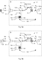
- the Figures 5a and 5b show an exemplary optical structure of a laser tracker according to the invention
- the Figure 5a its use in the first measurement functionality to determine the position of a cooperative, retroreflective Target 61 shows and Figure 5b the use for determining the position of a diffusely scattering target 64.
- the beam steering unit 10 has an optical distance measuring unit 2, which is designed in an integrated manner and accordingly fixedly arranged a first detection unit 12, in the example designed as an absolute distance measuring unit (ADM), a second detection unit 13, in the example designed as a wave-form digitizing Unit (WFD), and a first beam source 30, e.g. B. a HeNe laser beam source or a laser diode which generates the first measurement radiation 36.
- ADM absolute distance measuring unit
- WFD wave-form digitizing Unit
- first beam source 30 e.g. B. a HeNe laser beam source or a laser diode which generates the first measurement radiation 36.
- the first measurement radiation 36 emanating from the beam source 30 strikes a first variable beam splitter 131a, which can be switched between the two states in a transparent and reflective manner, for example by applying a voltage.
- a first measurement functionality after Figure 5a it is reflective, which is why the beam 36 in the Figure 5a deflected downwards and guided into the ADM by means of two deflection elements 135 (eg prisms).
- a corresponding guidance of the beam 36 is regulated by mechanically changing the beam splitter 131a (for example changing the rotational position) or by means of an additional optical element such as a diaphragm.
- ADM 13 The measurement signal of the ADM detector 132 becomes the Distance to target 61 is determined.
- Other ADM arrangements and methods can also be used in this context, e.g. B. phase-based or working according to the Fizeau principle detection units can be used.
- FIG 5b is the distance measuring unit 2 in the second measuring functionality.
- the first variable beam splitter 131a is in the transmissive state, which is why the pulsed first measurement radiation 36 from the beam source 30 is not deflected "downwards", but instead hits the partially transparent beam splitter 74 through the first variable beam splitter 131a.
- a reference beam 77 having the same measurement pulses as the WFD beam 36 is split off, which is directed to a reference beam coupling element 78 which couples the reference beam 77 into a first optical waveguide 79 which leads to the WFD unit 13.
- the other part of the WFD beam 36 is directed by the second variable beam splitter 131b, which is also in the transmissive state, and the laser emitting and receiving optics 51 onto the target 64 to be measured (surface of a diffusely scattering measurement object).
- a portion of the first measurement radiation 36 remitted from the diffusely scattering surface of the measurement object or from the target 64 passes through the laser emitting and receiving optics 51 back into the beam steering unit 10.
- the remitted radiation shows the measurement pulses corresponding to the distance to the target 64 - time-shifted target pulses on.
- the remitted radiation is bundled by a beam receiving unit (not shown) and passed through the permeable second variable beam splitter 131b and, if necessary, through others, not here
- the optical means shown are directed to a coupling unit 88 which couples the remitted radiation into a second optical waveguide 89 which leads to the WFD unit 13 or its detector. Both the remitted portion 81 of the WFD beam 76 and the reference beam 77 are recorded by the detector.
- the pulses of the remitted radiation and of the reference beam 77 are digitized in a known manner, referred to as waveform digitizing.
- the measurement pulses and target pulses digitized in this way are compared with one another, in particular the time interval between them, and the distance to the target point 64 is thus determined by the control and evaluation unit.
- Waveform Digitizing is based on the combination of two basic principles for signal detection that are common in distance measurement.
- the first basic principle is based on measurement signal detection using the threshold value method and the second basic principle on signal sampling with downstream signal processing for identification and timing of the signal.
- Both approaches are used in parallel to signal detection, that is, a received measurement pulse or a signal structure of the measurement radiation is detected with both methods, which mostly implies simultaneity or at least temporal overlap of the methods.
- the A combination of both principles allows the dynamic range to be expanded and additional information, such as the pulse energy, to be used for the detection of the signal and the derivation of distance information. Since the dynamic range of the receiving circuit has to be maximized for electro-optical distance meters in order to be able to cover as many types of measurement as possible, this combination of methods offers significant advantages.
- a distance measurement can be carried out simultaneously with the WFD 13 and the ADM 12, which can be used to calibrate the WFD.
- the first detection unit 12 is used singularly in the first measuring functionality
- the second detection unit 13 singularly in the second measuring functionality
- the first beam source 30 is used dual in both measuring functionalities.
- the first beam source 30 optionally generates different first measurement radiation 36 depending on the measurement functionality, e.g. for the second measurement functionality with WFD pulsed radiation (as described) and for the first measurement functionality with the ADM with continuous wave operation or e.g. by appropriate means (e.g.
- the beam steering unit 10 has a component 160 which separates incident light and decouples a first part of this light to the localization camera (not shown) and a second part to a surface sensor as a fine target sensor (not shown).
- the localization camera can have its own optics and also an image converter.
- the localization camera typically has an opening angle of around 10 ° and a focal length of, for example, 30 to 50 mm and is used for the rough localization of measurement targets.
- the beam steering unit 10 can have reflector lighting (not shown) with a specific lighting wavelength, which illuminates an angular range that is preferably at least as large as the opening angle of the overview camera.
- the control and evaluation unit is designed in such a way that one or more bright points of light are detected in the field of view of the localization camera, each of which corresponds to a reflective target. From this, their position in the image of the localization camera and, in turn, a direction to the target can be determined, with which the laser tracker or the beam steering unit 10 and the measuring radiation can be aligned with the target. Automatic target acquisition and "lock-on", ie continuous tracking of a target, can thus be implemented.
- the light component for the fine target sensor is preferably a bundle of rays from returning measurement radiation.
- the fine aiming unit can also have its own optics.
- the output signal of the area sensor is generated by means of one or more photosensitive areas and depends on the respective position of the Focus of light.
- the position of the center of gravity of the incident point of light can be determined very quickly (nanosecond range) and with a nanometer resolution.
- the point of impact of the detected beam is offset from a servo control zero point, and the laser beam is tracked to the target on the basis of the offset.
- the field of view of the area sensor is selected to be comparatively small, that is to say to correspond to the beam diameter of the measuring beam.
- a detection with the fine aiming sensor takes place coaxially to the measuring axis, so that the detection direction of the fine aiming corresponds to the measuring direction.
- the use of tracking and fine aiming takes place after the measuring beam has been at least roughly aligned with a retro-reflective target as described above (ie in such a way that the target lies within the light beam cone).
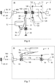
- the Figure 6 shows a further exemplary optical structure of a laser tracker according to the invention.
- the distance measuring unit 2 which is built into the beam steering unit 10, has, as in the example according to Figures 5a and 5b in turn a first detection unit 12 and a second detection unit 13, the second detection unit 13 also being used singularly only in one of the two measurement functionalities.
- the first detection unit 12 is not designed for singular use in one of the two measuring functionalities, but rather the first detection unit 12 is used dual in both measuring functionalities.
- a position determination takes place in a measurement functionality alone the first detection unit 12, in the other measuring functionality with a combination of the first and second detection units 12 and 13.
- the second detection unit 13 is therefore switched on in one of the two measuring functionalities.
- the first detection unit 12 is designed to determine an absolute distance
- the second detection unit 13 is designed to determine a relative distance with a finer resolution or higher precision than the first detection unit 12.
- the first detection unit 12 is fed by the first beam source 30, which is thus also used in dual form in both measurement functionalities, which in the example is designed as a laser diode or superluminescence LED (SLED).
- the dual use of the first beam source 30 is a common feature of the embodiments according to FIG Figure 5a, 5b and 6th .
- the second detection unit 13 is not fed by the first beam source 30, but rather the second detection unit 13 is supplied with second measurement radiation 37 from a second beam source 32.
- the distance to the target 61, 64 is determined in addition to the first measurement radiation 36 on the basis of the second measurement radiation 37.
- the first detection unit 12 is designed as a WFD unit.
- a diffusely scattering target 64 is measured with this in the second measurement functionality.
- the beam path of the first measurement radiation 36 or its components reflected by the target 64 is analogous to the example according to Figure 5b , wherein radiation 36 returning from target 64 is directed onto a coupling element 88 by means of a beam splitter 150 and possibly further optical means (not shown here).
- the beam splitter 150 can for example be dependent on the wavelength and the wavelength of the first measuring radiation 36 differs from the wavelength of the second measuring radiation 37.
- the second detection unit 13 is designed as an interferometer unit, which is used in the first measurement functionality (measurement to a retroreflector 61) in addition to the WFD unit, as in FIG Figure 6 shown, the target 61 is measured by means of the second measurement radiation 37 of the second beam source 32 in addition to the first measurement radiation 36.
- the first measurement radiation 36 reflected by the target 61 is evaluated by the WFD unit 12, the reflected second measurement radiation 37 by the interferometer unit 13, so that the distance is determined overall by means of the first measurement radiation 36 and the second measurement radiation 37.
- the distance to the target is determined by means of both detection units 12 and 13 or by means of both measuring beams 36 and 37, with the interferometer unit 13 providing or enabling increased accuracy, which is advantageous, for example, when measuring a retroreflective target 61 in a target-tracking manner is.
- the interferometer unit 13 uses light generated by the beam source 32, for example a longitudinal single-mode laser radiation with a large coherence length (single frequency).
- the generated light radiation is split by a beam splitter 121 into a reference radiation 122 on a reference light path and into a measurement radiation 37 on a measurement light path.
- the measuring light path leads through an acousto-optical modulator 125 and, together with the reference light path, hits a polarizing beam splitter 126.
- the polarizing beam splitter 126 forwards the measuring radiation 37 to the, e.g., wavelength-dependent beam splitter 150, and directs the returning measuring light together with the reference light via a polarization filter 123 to an interferometer detector 124.
- interferometer arrangement 13 The mode of operation of such an interferometer arrangement 13 is known in principle and is based on the wave interference principle.
- other interferometer arrangements and methods can also be used in which the measurement radiation can be coupled in and out through the beam splitter 150, for example.
- An example of such an interferometer is in WO 03/062744 A1 described.
- other types of interferometers e.g. Michelson with quadrature detection
- a superposition of the reference radiation 122 with the measuring radiation 37 retroreflected at a movable target 61 and guided onto the interferometer detector 124 is detected.
- the intensity of the interference that occurs when the two radiations 37, 122 are superimposed can be recorded continuously (as an interferometer output variable).
- the derivation of the interferometer output variable is based at least on the detected superimposition, the interferometer output variable depending on a distance to the target.
- the target 61 is at a constant distance from the interferometer detector 124, then the during the maintained fixed distance to the target 61 measured intensity value constant.
- the distance between the two components and thus a path difference between the reference radiation 122 and the measurement radiation 37 and thereby the Measurable intensity on the interferometer detector 124 as a function of the change in distance.
- these intensity variations in particular time-resolved, can be measured and recorded (as output variable curve) and read out and further processed for checking the correctness of such a distance change measurement.
- the time-resolved output variable is generated from the derived interferometer output variable, with the change in distance being determined based on the output variable.
- a movement parameter is optionally continuously derived from the intensities detected with the interferometer detector 124 and this parameter is continuously compared with a movement criterion. Depending on the comparison, information regarding the reliability of the measurement carried out is then output.
- the Figure 7 shows a further embodiment of the optical structure of a laser tracker according to the invention.
- the surveying device or the beam steering unit 10 has no second detector unit for distance measurement in addition to the first detector unit 12.
- the first detector unit 12 and the first beam source 30 supplying it are used dual both in the first and in the second measurement functionality, each in a different manner, specifically to the requirements of the measurement of a retroreflective target or the measurement of a diffusely scattering target and / or tracking or scanning.
- the beam source 30 can be operated in at least two different operating states or with different measurement parameters, for example with different power, pulse rate (or cw vs.
- the pulse mode and / or wavelength of the first measurement radiation 36 generated the first detection unit 12 can be operated in at least two different operating states or different measurement parameters, for example each with a different measurement rate and / or sensitivity.
- the same distance measuring unit 2 is used as a whole for both cooperative and natural targets 61, 64, the type of measurement being adapted to the respective target 61 or 64.
- optimal measurement results can be achieved or better measurement results compared to the alternative, unadapted use of the distance measurement unit 2, in which a mediocre compromise has to be made with regard to measurement parameters, which, however, is sufficient for some industrial measurement tasks.
- automatic detection of what type of target 61 or 64 is involved. Such an option is not limited to the present embodiment, but can also be implemented with all others.
- the first detection unit 12 is designed as an FMCW unit (frequency modulated continuous wave radar; frequency modulated continuous wave radar), which enables a distance measurement by means of an FMCW method.
- the distance measuring unit 2 can have a coherent laser radar for this purpose, such as. B. in the EP 1 869 397 B1 described.
- the approach used in this embodiment for distance measurement is to use frequency-modulated electromagnetic radiation, such as. B. emit light to the target to be measured and then receive one or more echoes from backscattering objects, ideally exclusively from the target to be measured. After reception, the possibly superimposed echo signal is superimposed with a mixed signal and thereby the frequency of the signal to be analyzed is reduced, so that only less effort is required on the device side.
- the mixing can take place either as a homodyne method with the transmitted signal or as a heterodyne method with a periodic, in particular harmonic, signal of known period.
- the purpose of the mix is to transform the received signal to lower frequencies. The transit times and thus - if the speed of propagation of the radiation used is known - the distances to the targets to be measured are then determined from the resulting signal.
- the devices used to implement these methods usually use a signal generator as a chirp generator which impresses a signal on a modulatable radiation source.
- a detector or receiver with a downstream mixer, A / D converter and digital signal processor are also used.
- a linear frequency-modulated chirp is generated by the signal generator as a measurement signal.
- the captured echo signal of the reflected measurement radiation is detected and combined with the mixed signal.
- the mixed signal is digitized and stored over a finite measuring interval. The transit times are determined from the frequency and, if applicable, the phase information of this signal. More precise results can be obtained by taking the phase information into account.
- a frequency-modulated method with continuous emission (FMCW method) for distance measurement with electromagnetic radiation in the radar range is from the DE 196 10 970 A1 known.
- the distance measuring unit 2 has the first beam source 30 with control means for generating a frequency-modulated first measuring beam 36 with a continuously variable frequency.
- the frequency-modulated laser beam 36 is first directed to a first beam splitter 74, as a result of which a reference beam 77 is split off, which is directed to a mixer element 178 by means of a deflecting element 135.
- the other part of the frequency-modulated laser beam 36 is guided by a second beam splitter 150, the laser emitting optics 51, onto the target 64 or 61. Portions of the frequency-modulated laser beam 36 remitted by the target 61, 64 partially pass through the laser receiving optics 51 again into the beam steering unit 10.
- the remitted radiation is guided by means of the second beam splitter 150 to the mixer element 178, in which the remitted radiation is homodyne with the reference beam 177 or mixed heterodyne.
- the remitted radiation can optionally have been amplified beforehand by means of an HF preamplifier.
- the resulting mixed signal 182 is guided to the first detection unit 12 by means of an optical fiber 79; in particular, the mixed signal can also be passed via a low-pass filter 187 and a baseband amplifier.
- a frequency difference ie. H. in particular a distance between the frequencies of the reference beam 177 and the remitted radiation, can be determined and the distance to the target 61 or 64 calculated therefrom.
- an optical reference system can be used for the reference beam 177.
- Such an optical reference system is for example in the EP 1 869 397 B1 described.
- a WFD method or a measuring of distances based on a frequency comb or supported by a frequency comb is used.
- the distance measuring unit has a first beam source 30 which is designed to emit a pulsed, high-precision timed femtosecond laser which has a carrier signal.
- a so-called frequency comb of thin, sharp lines can be generated in the frequency range, which can be used for precise optical frequency measurement.
Claims (15)
- Appareil de suivi laser (1) destiné à la détermination de position coordonnée industrielle d'une cible (61, 64), dans lequel l'appareil de suivi laser (1) comporte au moins• une base (40),• une unité de commande et de traitement destinée au traitement des données et à la commande de l'appareil de suivi laser (1),• une unité optique de mesure de distance (2) au moyen de laquelle une distance absolue jusqu'à la cible (61, 64) peut être déterminée pour la détermination de position coordonnée, dans lequel l'unité optique de mesure de distance (2) comporte au moins les éléments suivants∘ une première source de rayonnement (30), en particulier une LED superluminescente (SLED) ou source laser, destinée à produire un premier rayonnement de mesure (36) et∘ une première unité de détection (12) destinée à détecter le premier rayonnement de mesure (36) réfléchi et reçu,• une unité de déviation de rayonnement (10), laquelle peut tourner autour de deux axes par rapport à la base et comporte une optique d'émission et de réception (51) destinée à émettre le premier rayonnement de mesure (36) sur la cible (61, 64) et à recevoir le premier rayonnement de mesure (36) réfléchi et• des moyens destinés à saisir des angles de rotation de l'unité de déviation de rayonnement (10) par rapport à la base (40),caractérisé en ce que
l'unité de commande et de traitement et l'unité optique de mesure de distance (2) sont réalisées pour mettre en œuvre une première et une deuxième fonctionnalité de mesure, où au moins un élément de l'unité de mesure de distance (2) est réalisé pour double utilisation aussi bien dans la première que dans la deuxième fonctionnalité de mesure, dans lequel• l'unité de mesure de distance (2) est exécutée dans une conception intégrée,• la première fonctionnalité de mesure est réalisée pour la détermination de position coordonnée d'une cible rétroréfléchissante (61) et• la deuxième fonctionnalité de mesure est réalisée pour la détermination de position coordonnée d'une cible diffusante (64),de sorte qu'une détermination de position coordonnée adaptée au type respectif de cible (61, 64) peut être mise en œuvre. - Appareil de suivi laser (1) selon la revendication 1,
caractérisé en ce que
la première source de rayonnement (30) est un élément à double utilisation, en particulier dans lequel la première source de rayonnement (30) peut fonctionner dans différents états de fonctionnement, spécialement en ce qui concerne la puissance et/ou la durée d'émission du premier rayonnement de mesure (36) produit, pour la double utilisation. - Appareil de suivi laser (1) selon la revendication 1 ou 2,
caractérisé en ce que
l'appareil de suivi laser (1) est réalisé• pour le suivi en continu d'une cible rétroréfléchissante (61) en déplacement dans la première fonctionnalité de mesure et/ou• pour la mise en œuvre d'une pluralité de mesures de distance par rapport à une pluralité de cibles diffusantes (64) sur la surface (92) d'un objet de mesure (90) dans le cadre de la deuxième fonctionnalité de mesure, dans lequel l'unité de commande et de traitement est réalisée de telle sorte que∘ pour la pluralité de mesures de distance les angles de rotation respectivement saisis sont combinés avec la distance mesurée, de sorte qu'une position ponctuelle du point cible respectif (64) est respectivement définie par la combinaison, et∘ un nuage de points comportant un nombre des positions ponctuelles peut être produit. - Appareil de suivi laser (1) selon l'une des revendications précédentes,
caractérisé en ce que• l'unité de commande et de traitement comporte une fonctionnalité de commutation destinée à sélectionner automatiquement, en particulier à l'aide de la réflexion reçue du rayonnement de mesure, la fonctionnalité de mesure adaptée ou optimale pour la cible (61, 64) et/ou• l'appareil de suivi laser (1) comporte une unité optique de capture d'image (52) dotée d'un réseau photosensible bidimensionnel, en particulier une caméra de mesure à zoom Vario, et l'unité de commande et de traitement comporte une fonctionnalité de traitement d'image, de sorte que par capture et traitement d'image d'une image de l'unité de capture d'image l'orientation d'un instrument de mesure (60) comportant des marquages optiques (62) peut être déterminée et/ou• l'appareil de suivi laser (1) comporte une unité d'identification de cible dotée de moyens d'éclairage (54) et de caméras de localisation (53) et/ou• l'appareil de suivi laser (1) comporte une caméra d'observation destinée à fournir des images d'observation et/ou• l'appareil de suivi laser (1) comporte une unité de ciblage fin et de suivi dotée d'une source de rayonnement de ciblage fin et d'un capteur de ciblage fin, en particulier d'un capteur CMOS, d'un capteur CCD ou d'un capteur sensible à la position, destinée au ciblage fin et/ou au suivi en continu d'une cible rétroréfléchissante (61). - Appareil de suivi laser (1) selon l'une des revendications précédentes,
caractérisé en ce que
la première unité de détection (12) est réalisée pour la détermination de distances absolues, en particulier dans lequel la première unité de détection est réalisée comme unité WFD, unité FMCW, unité à peigne de fréquences ou interféromètre absolu, en particulier interféromètre à balayage de fréquences. - Appareil de suivi laser (1) selon l'une des revendications 2 à 5,
caractérisé en ce que
outre la première source de rayonnement (30), au moins un élément ultérieur de l'unité de mesure de distance (2) est réalisé pour la double utilisation. - Appareil de suivi laser (1) selon la revendication 6,
caractérisé en ce que
tous les éléments de l'unité de mesure de distance (2) sont réalisés pour la double utilisation, en particulier dans lequel au moins un des éléments peut fonctionner dans différents états de fonctionnement pour la double utilisation. - Appareil de suivi laser (1) selon l'une des revendications 1 à 6,
caractérisé en ce que
au moins un élément de l'unité de mesure de distance (2) est réalisé pour utilisation unique seulement dans la première ou seulement dans la deuxième fonctionnalité de mesure. - Appareil de suivi laser (1) selon la revendication 8,
caractérisé en ce que
un élément pour utilisation unique est une deuxième unité de détection (13), laquelle comporte l'unité de mesure de distance (2). - Appareil de suivi laser (1) selon la revendication 9,
caractérisé en ce que
l'unité de mesure de distance (2) est réalisée de telle façon que la première source de rayonnement (30) sert d'élément pour double utilisation, le premier rayonnement de mesure (36) produit par celle-ci est détectable par la première unité de détection (12) et également par la deuxième unité de détection (13), en particulier dans lequel• dans la première fonctionnalité de mesure la réflexion reçue du premier rayonnement de mesure (36) est détectée exclusivement par la première unité de détection (12) et• dans la deuxième fonctionnalité de mesure la réflexion reçue du premier rayonnement de mesure (36) est détectée exclusivement par la deuxième unité de détection (13), et/ou• la deuxième unité de détection (13) est réalisée comme unité de numérisation de forme d'onde et/ou• l'appareil de suivi laser (1) comporte au moins un élément de déviation (131a, 131b) optique variable destiné à influer sur le chemin optique du premier rayonnement de mesure (36). - Appareil de suivi laser (1) selon la revendication 9,
caractérisé en ce que
l'unité de mesure de distance (2) comporte, en tant qu'au moins un élément ultérieur pour utilisation unique, une deuxième source de rayonnement (32) destinée à produire le deuxième rayonnement de mesure (37) et la distance jusqu'à la cible (61, 64) est déterminée en utilisant en outre le deuxième rayonnement de mesure (37) ou bien dans la première ou bien dans la deuxième fonctionnalité de mesure. - Appareil de suivi laser (1) selon la revendication 11,
caractérisé en ce que
la deuxième unité de détection (13) est réalisée pour la détermination de distances relatives, en particulier comme unité d'interférométrie, et sert pour utilisation unique dans la première fonctionnalité de mesure, dans lequel le deuxième rayonnement de mesure (37) produit par la deuxième source de rayonnement (32) est détectable par la deuxième unité de détection (13). - Procédé de détermination de position coordonnée industrielle d'une cible (61, 64) avec un appareil de suivi laser (1), dans lequel
l'appareil de suivi laser (1) comporte au moins• une base (40),• une unité de commande et de traitement,• une unité de déviation de rayonnement (10) dotée d'une optique d'émission et de réception (51) destinée à émettre de la lumière comme rayonnement de mesure (36, 37) et à recevoir des réflexions de rayonnement de mesure, et• une unité optique de mesure de distance (2) dotée au moins des éléments suivantset dans lequel le procédé comprend au moins∘ d'une première source de rayonnement (30), en particulier une LED superluminescente (SLED) ou source laser, et∘ d'une première unité de détection (12),• production du premier rayonnement de mesure (36) par la première source de rayonnement (30),• émission du premier rayonnement de mesure (36) et réception du premier rayonnement de mesure (36) réfléchi par la cible (61, 64) au moyen de l'optique d'émission et de réception (51),• détection du premier rayonnement de mesure (36) réfléchi reçu, détermination d'une distance jusqu'à la cible (61, 64) à l'aide du rayonnement de mesure (36) détecté,• détermination des angles de rotation de l'unité de déviation de rayonnement (10) par rapport à la base (40),caractérisé en ce que
sur interrogation respectivement à l'aide des angles de rotation déterminés et d'au moins une distance déterminée• dans une première fonctionnalité de mesure une détermination de position coordonnée d'une cible rétroréfléchissante (61) et• dans une deuxième fonctionnalité de mesure une détermination de position coordonnée d'une cible diffusante (64)s'effectue, dans lequel au moins un élément de l'unité de mesure de distance (2) est utilisé de manière double aussi bien dans la première fonctionnalité de mesure que dans la deuxième fonctionnalité de mesure, de sorte qu'une détermination de position coordonnée adaptée au type respectif de la cible (61, 64) s'effectue. - Procédé selon la revendication 13,
caractérisé en ce que• la détermination d'une distance jusqu'à la cible (61, 64) s'effectue en utilisant le premier rayonnement de mesure (36) aussi bien dans la première que dans la deuxième fonctionnalité de mesure et/ou• dans le cadre du procédé un suivi en continu de la cible (61, 64) s'effectue. - Produit-programme informatique doté de code de programmation, enregistré sur un support lisible par machine, destiné à commander ou exécuter le procédé selon l'une des revendications 13 à 14, en particulier lorsque le programme est exécuté sur une unité de traitement des données électronique conçue comme unité de commande et de traitement d'un appareil de suivi laser (1) selon l'une des revendications 1 à 12.
Priority Applications (3)
| Application Number | Priority Date | Filing Date | Title |
|---|---|---|---|
| EP16160434.3A EP3220163B1 (fr) | 2016-03-15 | 2016-03-15 | Appareil de suivi laser à deux fonctionnalités de mesure |
| US15/458,867 US10444361B2 (en) | 2016-03-15 | 2017-03-14 | Laser tracker having two measurement functionalities |
| CN201710150070.9A CN107192380B (zh) | 2016-03-15 | 2017-03-14 | 确定目标的工业坐标位置的激光跟踪器、方法及存储介质 |
Applications Claiming Priority (1)
| Application Number | Priority Date | Filing Date | Title |
|---|---|---|---|
| EP16160434.3A EP3220163B1 (fr) | 2016-03-15 | 2016-03-15 | Appareil de suivi laser à deux fonctionnalités de mesure |
Publications (2)
| Publication Number | Publication Date |
|---|---|
| EP3220163A1 EP3220163A1 (fr) | 2017-09-20 |
| EP3220163B1 true EP3220163B1 (fr) | 2021-07-07 |
Family
ID=55532212
Family Applications (1)
| Application Number | Title | Priority Date | Filing Date |
|---|---|---|---|
| EP16160434.3A Active EP3220163B1 (fr) | 2016-03-15 | 2016-03-15 | Appareil de suivi laser à deux fonctionnalités de mesure |
Country Status (3)
| Country | Link |
|---|---|
| US (1) | US10444361B2 (fr) |
| EP (1) | EP3220163B1 (fr) |
| CN (1) | CN107192380B (fr) |
Families Citing this family (18)
| Publication number | Priority date | Publication date | Assignee | Title |
|---|---|---|---|---|
| US9383753B1 (en) * | 2012-09-26 | 2016-07-05 | Google Inc. | Wide-view LIDAR with areas of special attention |
| US9746560B2 (en) | 2013-02-12 | 2017-08-29 | Faro Technologies, Inc. | Combination scanner and tracker device having a focusing mechanism |
| EP3701311A4 (fr) * | 2017-10-26 | 2021-07-07 | Shenzhen Genorivision Technology Co. Ltd. | Source lumineuse de lidar |
| CN107765231A (zh) * | 2017-11-08 | 2018-03-06 | 中国人民解放军海军工程大学 | 一种地面三维激光雷达装置及其组装方法 |
| EP3489714A1 (fr) * | 2017-11-28 | 2019-05-29 | Hexagon Technology Center GmbH | Dispositif de mesure de distance optique pourvu d'ouverture de réception commutable |
| CN108089196B (zh) * | 2017-12-14 | 2021-11-19 | 中国科学院光电技术研究所 | 一种光学主被动融合的非合作目标位姿测量装置 |
| JP6722876B2 (ja) * | 2017-12-26 | 2020-07-15 | クモノスコーポレーション株式会社 | 三次元レーザー光走査装置 |
| US11079723B2 (en) | 2018-02-06 | 2021-08-03 | Integrated Device Technology, Inc. | Apparatus and methods for automatic time measurements |
| EP3579174A1 (fr) | 2018-06-08 | 2019-12-11 | Hexagon Technology Center GmbH | Véhicules mobiles dans la fabrication |
| DE102018115452A1 (de) * | 2018-06-27 | 2020-01-02 | Carl Zeiss Ag | Verfahren und Vorrichtung zur scannenden Abstandsermittlung eines Objekts |
| CN108844870B (zh) * | 2018-08-08 | 2021-09-21 | 重庆交通大学 | 基于光纤结构的pm10和pm2.5探测仪器装置和系统 |
| EP3623843B1 (fr) | 2018-09-11 | 2021-01-13 | Leica Geosystems AG | Appareil de mesure de distance laser portatif |
| JP7299669B2 (ja) * | 2019-08-28 | 2023-06-28 | 株式会社トプコン | ガイド光照射部を備えた測量機 |
| CN110806584A (zh) * | 2019-09-29 | 2020-02-18 | 四川大学 | 能在测量中进行测量功能转换的激光测量装置及测试方法 |
| CN111912289A (zh) * | 2020-08-10 | 2020-11-10 | 安徽信息工程学院 | 一种自行式电磁火炮控制系统、方法和装置 |
| CN112711006B (zh) * | 2021-01-07 | 2023-08-22 | 深圳市中图仪器股份有限公司 | 一种光纤化的激光测距系统 |
| CN112882048A (zh) * | 2021-01-11 | 2021-06-01 | 广州合智瑞达科技有限公司 | 用于运动物体高精度测距的雷达装置及其测量方法 |
| CN115902834A (zh) * | 2022-12-02 | 2023-04-04 | 中国科学技术大学 | 基于斐索干涉仪的氦激光雷达双频测温测风系统及方法 |
Family Cites Families (10)
| Publication number | Priority date | Publication date | Assignee | Title |
|---|---|---|---|---|
| US5198877A (en) | 1990-10-15 | 1993-03-30 | Pixsys, Inc. | Method and apparatus for three-dimensional non-contact shape sensing |
| DE19610970A1 (de) | 1996-03-20 | 1997-09-25 | Reinhard Dipl Ing Stolle | Radarverfahren und -vorrichtung zur Messung von Entfernungen und Geschwindigkeiten |
| WO2003062744A1 (fr) | 2002-01-16 | 2003-07-31 | Faro Technologies, Inc. | Dispositif et procede de mesure de coordonnees par laser |
| US20060280415A1 (en) | 2005-03-17 | 2006-12-14 | Anthony Slotwinski | Precision length standard for coherent laser radar |
| EP2261601B1 (fr) | 2006-01-13 | 2013-06-26 | Leica Geosystems AG | Dispositif de mesure de coordonnées |
| EP2557391A1 (fr) | 2011-08-12 | 2013-02-13 | Leica Geosystems AG | Appareil de mesure destiné à la détermination de la position dans l'espace d'un instrument d'aide à la mesure |
| EP2589982A1 (fr) * | 2011-11-03 | 2013-05-08 | Leica Geosystems AG | Diode laser comme source de rayonnement laser d'interféromètre dans un appareil de suivi laser |
| US9746560B2 (en) * | 2013-02-12 | 2017-08-29 | Faro Technologies, Inc. | Combination scanner and tracker device having a focusing mechanism |
| US9036134B2 (en) | 2013-02-12 | 2015-05-19 | Faro Technologies, Inc. | Multi-mode optical measurement device and method of operation |
| EP2827099A1 (fr) | 2013-07-16 | 2015-01-21 | Leica Geosystems AG | Appareil de suivi laser avec fonctionnalité de recherche d'objectif |
-
2016
- 2016-03-15 EP EP16160434.3A patent/EP3220163B1/fr active Active
-
2017
- 2017-03-14 US US15/458,867 patent/US10444361B2/en active Active
- 2017-03-14 CN CN201710150070.9A patent/CN107192380B/zh active Active
Also Published As
| Publication number | Publication date |
|---|---|
| CN107192380B (zh) | 2020-04-24 |
| US10444361B2 (en) | 2019-10-15 |
| CN107192380A (zh) | 2017-09-22 |
| EP3220163A1 (fr) | 2017-09-20 |
| US20170269213A1 (en) | 2017-09-21 |
Similar Documents
| Publication | Publication Date | Title |
|---|---|---|
| EP3220163B1 (fr) | Appareil de suivi laser à deux fonctionnalités de mesure | |
| EP3032277B1 (fr) | Appareil de suivi laser | |
| DE102004037137B4 (de) | Verfahren und Vorrichtung zur Entfernungsmessung | |
| EP2810020B1 (fr) | Dispositif d'arpentage doté d'une fonctionnalité de balayage et d'un mode de mesure à point unique | |
| EP2820444B1 (fr) | Procédé de détermination d'une modification d'éloignement par interférométrie | |
| EP2801841B1 (fr) | Appareil de suivi laser comprenant une unité d'enregistrement d'une cible pour le pistage d'une cible et une détection d'orientation | |
| EP0987564B1 (fr) | Dispositif permettant de mesurer des distances | |
| EP2475953B1 (fr) | Dispositifs et procédés de détermination de position et de mesure de surface | |
| DE102008045386B4 (de) | Vorrichtung und Verfahren zum Bestimmen einer Objektposition | |
| EP2875383B1 (fr) | Appareil de suivi laser avec unité de calibrage pour calibrage automatique | |
| EP2773980B1 (fr) | Diode laser comme source de rayonnement laser d'interféromètre dans un appareil de suivi laser | |
| EP2847613B1 (fr) | Appareil de suivi laser doté d'un interféromètre et unité de mesure de distance absolue ainsi que procédé de calibrage pour un appareil de suivi laser | |
| EP3165876A2 (fr) | Appareil de mesure optoélectronique | |
| DE112012007096B4 (de) | Trackereinheit und Verfahren in einer Trackereinheit | |
| EP2746806A1 (fr) | Appareil de suivi laser à calibrage automatique et procédé de calibrage automatique | |
| WO2011127617A1 (fr) | Appareil de mesure de coordonnées à détection de cible automatique | |
| EP3845859B1 (fr) | Appareil de mesure de coordonnées doté d'une reconnaissance d'objet cible automatique | |
| WO2012028388A1 (fr) | Unité de mesure, système de mesure et procédé de détermination d'une position relative et d'une orientation relative | |
| WO2011036033A1 (fr) | Procédé et dispositifs de détermination de l'orientation et de la positon d'un objet | |
| EP2772719B1 (fr) | Dispositif optique | |
| WO2015003833A1 (fr) | Détermination d'une distance et d'un angle par rapport à un plan au moyen de plusieurs mesures d'éloignement | |
| EP4298459A1 (fr) | Dispositif de poursuite laser à deux fonctionnalités de mesure et mesure de distance fmcw | |
| DE102016006776A1 (de) | Vorrichtung und Verfahren zur eindeutigen Abstandsmessung mit moduliertem LIDAR |
Legal Events
| Date | Code | Title | Description |
|---|---|---|---|
| PUAI | Public reference made under article 153(3) epc to a published international application that has entered the european phase |
Free format text: ORIGINAL CODE: 0009012 |
|
| STAA | Information on the status of an ep patent application or granted ep patent |
Free format text: STATUS: THE APPLICATION HAS BEEN PUBLISHED |
|
| AK | Designated contracting states |
Kind code of ref document: A1 Designated state(s): AL AT BE BG CH CY CZ DE DK EE ES FI FR GB GR HR HU IE IS IT LI LT LU LV MC MK MT NL NO PL PT RO RS SE SI SK SM TR |
|
| AX | Request for extension of the european patent |
Extension state: BA ME |
|
| STAA | Information on the status of an ep patent application or granted ep patent |
Free format text: STATUS: REQUEST FOR EXAMINATION WAS MADE |
|
| 17P | Request for examination filed |
Effective date: 20180316 |
|
| RBV | Designated contracting states (corrected) |
Designated state(s): AL AT BE BG CH CY CZ DE DK EE ES FI FR GB GR HR HU IE IS IT LI LT LU LV MC MK MT NL NO PL PT RO RS SE SI SK SM TR |
|
| GRAP | Despatch of communication of intention to grant a patent |
Free format text: ORIGINAL CODE: EPIDOSNIGR1 |
|
| STAA | Information on the status of an ep patent application or granted ep patent |
Free format text: STATUS: GRANT OF PATENT IS INTENDED |
|
| INTG | Intention to grant announced |
Effective date: 20210311 |
|
| GRAS | Grant fee paid |
Free format text: ORIGINAL CODE: EPIDOSNIGR3 |
|
| GRAA | (expected) grant |
Free format text: ORIGINAL CODE: 0009210 |
|
| STAA | Information on the status of an ep patent application or granted ep patent |
Free format text: STATUS: THE PATENT HAS BEEN GRANTED |
|
| AK | Designated contracting states |
Kind code of ref document: B1 Designated state(s): AL AT BE BG CH CY CZ DE DK EE ES FI FR GB GR HR HU IE IS IT LI LT LU LV MC MK MT NL NO PL PT RO RS SE SI SK SM TR |
|
| REG | Reference to a national code |
Ref country code: GB Ref legal event code: FG4D Free format text: NOT ENGLISH |
|
| REG | Reference to a national code |
Ref country code: AT Ref legal event code: REF Ref document number: 1409120 Country of ref document: AT Kind code of ref document: T Effective date: 20210715 |
|
| REG | Reference to a national code |
Ref country code: DE Ref legal event code: R096 Ref document number: 502016013344 Country of ref document: DE |
|
| REG | Reference to a national code |
Ref country code: IE Ref legal event code: FG4D Free format text: LANGUAGE OF EP DOCUMENT: GERMAN |
|
| REG | Reference to a national code |
Ref country code: LT Ref legal event code: MG9D |
|
| REG | Reference to a national code |
Ref country code: NL Ref legal event code: MP Effective date: 20210707 |
|
| PG25 | Lapsed in a contracting state [announced via postgrant information from national office to epo] |
Ref country code: LT Free format text: LAPSE BECAUSE OF FAILURE TO SUBMIT A TRANSLATION OF THE DESCRIPTION OR TO PAY THE FEE WITHIN THE PRESCRIBED TIME-LIMIT Effective date: 20210707 Ref country code: BG Free format text: LAPSE BECAUSE OF FAILURE TO SUBMIT A TRANSLATION OF THE DESCRIPTION OR TO PAY THE FEE WITHIN THE PRESCRIBED TIME-LIMIT Effective date: 20211007 Ref country code: NL Free format text: LAPSE BECAUSE OF FAILURE TO SUBMIT A TRANSLATION OF THE DESCRIPTION OR TO PAY THE FEE WITHIN THE PRESCRIBED TIME-LIMIT Effective date: 20210707 Ref country code: PT Free format text: LAPSE BECAUSE OF FAILURE TO SUBMIT A TRANSLATION OF THE DESCRIPTION OR TO PAY THE FEE WITHIN THE PRESCRIBED TIME-LIMIT Effective date: 20211108 Ref country code: NO Free format text: LAPSE BECAUSE OF FAILURE TO SUBMIT A TRANSLATION OF THE DESCRIPTION OR TO PAY THE FEE WITHIN THE PRESCRIBED TIME-LIMIT Effective date: 20211007 Ref country code: ES Free format text: LAPSE BECAUSE OF FAILURE TO SUBMIT A TRANSLATION OF THE DESCRIPTION OR TO PAY THE FEE WITHIN THE PRESCRIBED TIME-LIMIT Effective date: 20210707 Ref country code: FI Free format text: LAPSE BECAUSE OF FAILURE TO SUBMIT A TRANSLATION OF THE DESCRIPTION OR TO PAY THE FEE WITHIN THE PRESCRIBED TIME-LIMIT Effective date: 20210707 Ref country code: HR Free format text: LAPSE BECAUSE OF FAILURE TO SUBMIT A TRANSLATION OF THE DESCRIPTION OR TO PAY THE FEE WITHIN THE PRESCRIBED TIME-LIMIT Effective date: 20210707 Ref country code: RS Free format text: LAPSE BECAUSE OF FAILURE TO SUBMIT A TRANSLATION OF THE DESCRIPTION OR TO PAY THE FEE WITHIN THE PRESCRIBED TIME-LIMIT Effective date: 20210707 Ref country code: SE Free format text: LAPSE BECAUSE OF FAILURE TO SUBMIT A TRANSLATION OF THE DESCRIPTION OR TO PAY THE FEE WITHIN THE PRESCRIBED TIME-LIMIT Effective date: 20210707 |
|
| PG25 | Lapsed in a contracting state [announced via postgrant information from national office to epo] |
Ref country code: PL Free format text: LAPSE BECAUSE OF FAILURE TO SUBMIT A TRANSLATION OF THE DESCRIPTION OR TO PAY THE FEE WITHIN THE PRESCRIBED TIME-LIMIT Effective date: 20210707 Ref country code: LV Free format text: LAPSE BECAUSE OF FAILURE TO SUBMIT A TRANSLATION OF THE DESCRIPTION OR TO PAY THE FEE WITHIN THE PRESCRIBED TIME-LIMIT Effective date: 20210707 Ref country code: GR Free format text: LAPSE BECAUSE OF FAILURE TO SUBMIT A TRANSLATION OF THE DESCRIPTION OR TO PAY THE FEE WITHIN THE PRESCRIBED TIME-LIMIT Effective date: 20211008 |
|
| REG | Reference to a national code |
Ref country code: DE Ref legal event code: R097 Ref document number: 502016013344 Country of ref document: DE |
|
| PG25 | Lapsed in a contracting state [announced via postgrant information from national office to epo] |
Ref country code: DK Free format text: LAPSE BECAUSE OF FAILURE TO SUBMIT A TRANSLATION OF THE DESCRIPTION OR TO PAY THE FEE WITHIN THE PRESCRIBED TIME-LIMIT Effective date: 20210707 |
|
| PLBE | No opposition filed within time limit |
Free format text: ORIGINAL CODE: 0009261 |
|
| STAA | Information on the status of an ep patent application or granted ep patent |
Free format text: STATUS: NO OPPOSITION FILED WITHIN TIME LIMIT |
|
| PG25 | Lapsed in a contracting state [announced via postgrant information from national office to epo] |
Ref country code: SM Free format text: LAPSE BECAUSE OF FAILURE TO SUBMIT A TRANSLATION OF THE DESCRIPTION OR TO PAY THE FEE WITHIN THE PRESCRIBED TIME-LIMIT Effective date: 20210707 Ref country code: SK Free format text: LAPSE BECAUSE OF FAILURE TO SUBMIT A TRANSLATION OF THE DESCRIPTION OR TO PAY THE FEE WITHIN THE PRESCRIBED TIME-LIMIT Effective date: 20210707 Ref country code: RO Free format text: LAPSE BECAUSE OF FAILURE TO SUBMIT A TRANSLATION OF THE DESCRIPTION OR TO PAY THE FEE WITHIN THE PRESCRIBED TIME-LIMIT Effective date: 20210707 Ref country code: EE Free format text: LAPSE BECAUSE OF FAILURE TO SUBMIT A TRANSLATION OF THE DESCRIPTION OR TO PAY THE FEE WITHIN THE PRESCRIBED TIME-LIMIT Effective date: 20210707 Ref country code: CZ Free format text: LAPSE BECAUSE OF FAILURE TO SUBMIT A TRANSLATION OF THE DESCRIPTION OR TO PAY THE FEE WITHIN THE PRESCRIBED TIME-LIMIT Effective date: 20210707 Ref country code: AL Free format text: LAPSE BECAUSE OF FAILURE TO SUBMIT A TRANSLATION OF THE DESCRIPTION OR TO PAY THE FEE WITHIN THE PRESCRIBED TIME-LIMIT Effective date: 20210707 |
|
| 26N | No opposition filed |
Effective date: 20220408 |
|
| PG25 | Lapsed in a contracting state [announced via postgrant information from national office to epo] |
Ref country code: IT Free format text: LAPSE BECAUSE OF FAILURE TO SUBMIT A TRANSLATION OF THE DESCRIPTION OR TO PAY THE FEE WITHIN THE PRESCRIBED TIME-LIMIT Effective date: 20210707 |
|
| PG25 | Lapsed in a contracting state [announced via postgrant information from national office to epo] |
Ref country code: MC Free format text: LAPSE BECAUSE OF FAILURE TO SUBMIT A TRANSLATION OF THE DESCRIPTION OR TO PAY THE FEE WITHIN THE PRESCRIBED TIME-LIMIT Effective date: 20210707 |
|
| REG | Reference to a national code |
Ref country code: CH Ref legal event code: PL |
|
| REG | Reference to a national code |
Ref country code: BE Ref legal event code: MM Effective date: 20220331 |
|
| PG25 | Lapsed in a contracting state [announced via postgrant information from national office to epo] |
Ref country code: LU Free format text: LAPSE BECAUSE OF NON-PAYMENT OF DUE FEES Effective date: 20220315 Ref country code: LI Free format text: LAPSE BECAUSE OF NON-PAYMENT OF DUE FEES Effective date: 20220331 Ref country code: IE Free format text: LAPSE BECAUSE OF NON-PAYMENT OF DUE FEES Effective date: 20220315 Ref country code: CH Free format text: LAPSE BECAUSE OF NON-PAYMENT OF DUE FEES Effective date: 20220331 |
|
| PG25 | Lapsed in a contracting state [announced via postgrant information from national office to epo] |
Ref country code: BE Free format text: LAPSE BECAUSE OF NON-PAYMENT OF DUE FEES Effective date: 20220331 |
|
| PGFP | Annual fee paid to national office [announced via postgrant information from national office to epo] |
Ref country code: FR Payment date: 20230324 Year of fee payment: 8 |
|
| REG | Reference to a national code |
Ref country code: AT Ref legal event code: MM01 Ref document number: 1409120 Country of ref document: AT Kind code of ref document: T Effective date: 20220315 |
|
| PGFP | Annual fee paid to national office [announced via postgrant information from national office to epo] |
Ref country code: GB Payment date: 20230322 Year of fee payment: 8 Ref country code: DE Payment date: 20220620 Year of fee payment: 8 |
|
| PG25 | Lapsed in a contracting state [announced via postgrant information from national office to epo] |
Ref country code: AT Free format text: LAPSE BECAUSE OF NON-PAYMENT OF DUE FEES Effective date: 20220315 |
|
| PG25 | Lapsed in a contracting state [announced via postgrant information from national office to epo] |
Ref country code: HU Free format text: LAPSE BECAUSE OF FAILURE TO SUBMIT A TRANSLATION OF THE DESCRIPTION OR TO PAY THE FEE WITHIN THE PRESCRIBED TIME-LIMIT; INVALID AB INITIO Effective date: 20160315 |