EP2589982A1 - Diode laser comme source de rayonnement laser d'interféromètre dans un appareil de suivi laser - Google Patents
Diode laser comme source de rayonnement laser d'interféromètre dans un appareil de suivi laser Download PDFInfo
- Publication number
- EP2589982A1 EP2589982A1 EP11187614.0A EP11187614A EP2589982A1 EP 2589982 A1 EP2589982 A1 EP 2589982A1 EP 11187614 A EP11187614 A EP 11187614A EP 2589982 A1 EP2589982 A1 EP 2589982A1
- Authority
- EP
- European Patent Office
- Prior art keywords
- laser
- interferometer
- distance
- unit
- measuring
- Prior art date
- Legal status (The legal status is an assumption and is not a legal conclusion. Google has not performed a legal analysis and makes no representation as to the accuracy of the status listed.)
- Withdrawn
Links
Images

Classifications
-
- G—PHYSICS
- G01—MEASURING; TESTING
- G01B—MEASURING LENGTH, THICKNESS OR SIMILAR LINEAR DIMENSIONS; MEASURING ANGLES; MEASURING AREAS; MEASURING IRREGULARITIES OF SURFACES OR CONTOURS
- G01B11/00—Measuring arrangements characterised by the use of optical techniques
- G01B11/14—Measuring arrangements characterised by the use of optical techniques for measuring distance or clearance between spaced objects or spaced apertures
-
- G—PHYSICS
- G01—MEASURING; TESTING
- G01C—MEASURING DISTANCES, LEVELS OR BEARINGS; SURVEYING; NAVIGATION; GYROSCOPIC INSTRUMENTS; PHOTOGRAMMETRY OR VIDEOGRAMMETRY
- G01C15/00—Surveying instruments or accessories not provided for in groups G01C1/00 - G01C13/00
- G01C15/002—Active optical surveying means
-
- G—PHYSICS
- G01—MEASURING; TESTING
- G01B—MEASURING LENGTH, THICKNESS OR SIMILAR LINEAR DIMENSIONS; MEASURING ANGLES; MEASURING AREAS; MEASURING IRREGULARITIES OF SURFACES OR CONTOURS
- G01B11/00—Measuring arrangements characterised by the use of optical techniques
-
- G—PHYSICS
- G01—MEASURING; TESTING
- G01B—MEASURING LENGTH, THICKNESS OR SIMILAR LINEAR DIMENSIONS; MEASURING ANGLES; MEASURING AREAS; MEASURING IRREGULARITIES OF SURFACES OR CONTOURS
- G01B11/00—Measuring arrangements characterised by the use of optical techniques
- G01B11/002—Measuring arrangements characterised by the use of optical techniques for measuring two or more coordinates
-
- G—PHYSICS
- G01—MEASURING; TESTING
- G01B—MEASURING LENGTH, THICKNESS OR SIMILAR LINEAR DIMENSIONS; MEASURING ANGLES; MEASURING AREAS; MEASURING IRREGULARITIES OF SURFACES OR CONTOURS
- G01B5/00—Measuring arrangements characterised by the use of mechanical techniques
- G01B5/004—Measuring arrangements characterised by the use of mechanical techniques for measuring coordinates of points
-
- G—PHYSICS
- G01—MEASURING; TESTING
- G01C—MEASURING DISTANCES, LEVELS OR BEARINGS; SURVEYING; NAVIGATION; GYROSCOPIC INSTRUMENTS; PHOTOGRAMMETRY OR VIDEOGRAMMETRY
- G01C15/00—Surveying instruments or accessories not provided for in groups G01C1/00 - G01C13/00
-
- G—PHYSICS
- G01—MEASURING; TESTING
- G01S—RADIO DIRECTION-FINDING; RADIO NAVIGATION; DETERMINING DISTANCE OR VELOCITY BY USE OF RADIO WAVES; LOCATING OR PRESENCE-DETECTING BY USE OF THE REFLECTION OR RERADIATION OF RADIO WAVES; ANALOGOUS ARRANGEMENTS USING OTHER WAVES
- G01S17/00—Systems using the reflection or reradiation of electromagnetic waves other than radio waves, e.g. lidar systems
- G01S17/66—Tracking systems using electromagnetic waves other than radio waves
Definitions
- the invention relates to a measuring device, in particular a laser tracker, with an interferometer with laser diode for determining a distance change relative to a target according to the preamble of claim 1, a use of a laser diode with a large coherence length in a corresponding interferometer according to claim 13 and a method for determining a relative distance to the destination of claim 14.
- a target point may be represented by a retro-reflective unit (such as a cube prism) targeted by an optical measuring beam of the measuring device, in particular a laser beam.
- the laser beam is reflected back parallel to the measuring device, the reflected beam being detected by a detection unit of the device.
- an emission or reception direction of the beam for example by means of sensors for angle measurement, which are assigned to a deflection mirror or a target unit of the system, determined.
- a distance from the measuring device to the target point e.g. by means of transit time or phase difference measurement or by means of the Fizeau principle, and - increasingly standardized in modern systems - determined on a sensor storage of the received beam from a zero position.
- Retroreflektors and the point of impact of the laser beam on the reflector determined and the orientation of the laser beam in response to this deviation are corrected or tracked so that the shelf on the sensor is reduced, in particular "zero", and thus the beam aligned in the direction of the reflector center is.
- the tracking can be realized by means of an alignment change of the motorized movable, provided for deflecting the laser beam deflection mirror and / or by pivoting the target unit, which has the beam-guiding laser optics.
- Prior art laser trackers may additionally be implemented with an optical imaging unit having a two-dimensional photosensitive array, eg a CCD or CID camera or a CMOS array based camera, or with a pixel array sensor and with an image processing unit.
- the laser tracker and the camera are mounted on one another in such a way that their positions relative to one another can not be changed.
- the camera is rotatable, for example, together with the laser tracker about its substantially vertical axis, but independently of the laser tracker up and down pivotally and thus arranged in particular separated from the optics of the laser beam.
- the camera may have a fisheye lens and thus avoids pivoting of the camera due to a very large image capture range of the camera or at least partially necessary be.
- the camera - for example, depending on the particular application - be performed only pivotable about an axis.
- the camera can be installed in integrated construction with the laser optics together in a common housing.
- an orientation of an object (for example a probe) arranged in the auxiliary measuring instrument in space can be deduced. Furthermore, together with the determined spatial position of the target point, the position and orientation of the object in space absolutely and / or relative to the laser tracker can be precisely determined.
- the object whose position and orientation is measured with the aforementioned measuring device does not have to be a measuring probe itself but can be the auxiliary measuring instrument. This is brought as part of the measuring system for the measurement in a relative to the target object mechanically defined or determinable during the measurement position, which can be closed about its measured position and orientation to the position and, where appropriate, the orientation, for example, the probe.
- auxiliary measuring instruments can be embodied by so-called feeler tools, which are positioned with their point of contact on a point of the target object.
- the stylus has markers, such as light spots, and a reflector, which represents a target point on the stylus and with the laser beam of the tracker is targeted, wherein the positions of the markers and the reflector relative to the contact point of the Tasttechnikmaschinees are precisely known.
- the auxiliary measuring instrument may also be, for example, a hand-held, distance measuring scanner for non-contact surface measurements, the direction and position of the scanner measuring beam used for the distance measurement being relative to the points of light and reflectors arranged on the scanner. are known exactly.
- a scanner is for example in the EP 0 553 266 described.
- laser trackers of the prior art comprise at least one distance meter, this being known e.g. can be designed as an interferometer. Since such distance measuring units can only measure relative distance changes, in today's laser trackers so-called absolute distance meters are installed in addition to interferometers. For example, such a combination of measuring means for determining the distance is known by the LTD500 product of Leica Geosystems AG.
- the interferometers used for the distance measurement in this context mainly use HeNe gas lasers as light sources due to the large coherence length and the measurement range which is thus made possible.
- the coherence length of the HeNe laser can be several hundred meters, so that the required in industrial metrology ranges can be achieved with relatively simple interferometer structures.
- a disadvantage of the use of HeNe laser light sources in terms of a generally desired miniaturization of Lasertrackern whose determining the light output size.
- the power of the light source depends significantly on the length of the laser tube, i. the longer the tube, the greater the achievable emission power.
- such a laser source usually exhibits a relatively large power dissipation.
- a further disadvantage is the high-voltage supply required for the operation. For example, for the ignition of the laser a voltage of approximately 7,000V and during operation a voltage of approximately 1,500V must be provided, whereby special components are used when using such light sources (eg high voltage power supply and shielding) used and security measures must be taken.
- a specific object of the invention is to provide a laser tracker with an improved distance measuring unit in terms of space, wherein a required precision is at least maintained for a distance measurement of at least 10 m required for the distance determination.
- a further specific object of the invention is to provide a laser tracker with an interferometer as a distance meter, the optical components, in particular the beam source and supply units to be provided for this, having a significantly smaller space requirement and lower energy consumption compared to the prior art.
- the invention relates to a laser tracker for continuously tracking a reflecting target and determining distance to the target with a standing axis defining base and a beam steering unit for emitting a measuring radiation and for receiving at least a portion of the measuring radiation reflected at the target, wherein the beam steering unit about the vertical axis and a substantially orthogonal to the standing axis standing axis of inclination is motorized pivotable relative to the base.
- the standing axis and the tilt axis are positioned to each other such that between the axes an angle of exactly 90 ° or of approximately 90 °, for example 88.5 °, is present, with a relative axis position defined exactly and corresponding position values can be stored in the laser tracker, in particular for a compensation of measured values.
- the laser tracker has a distance measuring unit designed as an interferometer, in particular with a defined detector bandwidth, eg of 50 MHz, for determining a change in distance to the target by means of interferometry, an interferometer laser beam source for generating the measuring radiation for the interferometer and an angle measuring functionality for determining an alignment of the beam steering unit relative to the base.
- the interferometer laser beam source is designed as a laser diode, wherein the laser diode is further formed such that the measurement radiation is generated longitudinally monomodal with a defined emission wavelength and with a coherence length of at least 10m, in particular wherein the coherence length of at least 10m by means of the interferometer can be determined.
- the laser diode can be designed such that the measuring radiation can be generated with a coherence length of at least 20 m, in particular at least 50 m.
- the emission wavelength of the measuring radiation can be between 600 nm and 700 nm, in particular between 630 nm and 635 nm, or between 850 nm and 900 nm, in particular between 850 nm and 855 nm or between 892 nm and 896 nm.
- the emitted red laser light of the diode can be used not only for interferometric measurements but also as marker light. With the creation of a red spot on a target object, for example, a target of the laser tracker can be visualized visually.
- the laser tracker can have a control unit and the laser diode can be designed such that the emission wavelength of the measurement radiation can be varied longitudinally monomodally within a specific emission wavelength range.
- the emission wavelength can be varied by a temperature change of the laser diode and / or a change of an applied voltage applied to the laser diode controlled by the control unit.
- the laser diode can be driven in such a way by means of the control unit be that an emission power of the measuring radiation is variable.
- the wavelength within a certain range whereby the emitted radiation is single-modal, i. essentially with a specific, sharply defined wavelength (narrow linewidth)
- a tunable and, in particular, fashion-hop-free wavelength range can be provided for the emission wavelength.
- the radiation can also be tuned to an absorption line defined by a wavelength stabilization unit.
- the laser tracker can for this purpose have a wavelength stabilization unit for stabilizing the measurement radiation generated by the laser diode so that the emission wavelength is continuously within a defined wavelength range, in particular wherein the wavelength stabilization unit is designed as an absorption cell.
- a wavelength stabilization unit for stabilizing the measurement radiation generated by the laser diode so that the emission wavelength is continuously within a defined wavelength range, in particular wherein the wavelength stabilization unit is designed as an absorption cell.
- the wavelength stabilization unit may be formed as an external gas cell with a defined absorption line (absorption cell) (e.g., 633 nm iodine cell).
- the laser tracker can have an optical connecting fiber for connecting the wavelength stabilizing unit to the interferometer laser beam source.
- the radiation generated by the laser beam source by means of Connection fiber guided to the wavelength stabilization unit and coupled into this.
- the laser tracker generally have at least one optical fiber, wherein the measuring radiation is feasible by means of the optical fiber, in particular to the interferometer can be guided, in particular wherein by the laser diode generated measuring radiation is coupled into the optical fiber.
- the measuring radiation can thus be coupled into the beam steering unit by means of the optical fiber.
- optical components such as the wavelength stabilization unit or beam source can be arranged in different parts of the laser tracker.
- the beam source may for example be integrated in the base or a support of the tracker and the stabilization unit in a targeting unit (or vice versa). This can increase the flexibility in terms of the structural design of the tracker.
- the laser tracker may according to the invention have a support pivotable about the standing axis relative to the base, and the beam steering unit may be formed as a targeting unit pivotable relative to the support about the inclination axis.
- the laser beam may be caused by pivoting the support substantially horizontally (azimuthally) relative to the base and pivoting the aiming unit substantially vertically (elevatively) relative to the support be aligned.
- a guidance of the measuring beam in accordance with a change in position of the reflecting target eg retroreflector on a feeler tool
- the laser diode can be arranged in the targeting unit, wherein the associated space savings (compared to the previous use of gas laser beam sources) can represent a significant advantage in terms of constructive design of the laser tracker.
- the laser tracker can additionally have an absolute distance measurement unit for determining a distance to the target, in particular according to the principle of transit time measurement and / or according to the phase measurement principle and / or according to the Fizeau principle.
- a precision distance to the destination can be determined as a function of the distance determined by means of the absolute distance measuring unit and the distance change determined by means of the distance measuring unit.
- the interferometer provides highly accurate distance readings.
- the two distance measuring devices can each have a beam source, in particular with different emission wavelengths (eg, depending on the respectively installed detector).
- the invention further relates to the use of a laser diode which is designed to generate a longitudinal monomode measuring radiation having a defined emission wavelength and a coherence length of at least 10 m, in particular at least 20 m or 50 m, in a distance measuring unit designed as an interferometer of a laser tracker for determining a change in distance a target by interferometry by means of the measuring radiation generated by the laser diode.
- the laser diode or interferometer beam source and the other beam-influencing components may be present in different embodiments within the scope of the invention.
- visible red e.g., near 633 nm
- wavelength stabilized laser radiation can be generated, with high compatibility with already available system components (e.g., retroreflectors) achievable and, in addition, no additional visible pointer becomes necessary.
- the light source and absorption cell may be spatially separated, e.g. the light source in the telescope of the tracker and connected via a fiber to the absorption cell in the support.
- the laser diode can be designed to emit visible, non-wavelength-stabilized radiation.
- a reference interferometer together with an absolute distance meter
- such non-stabilized laser radiation can be used.
- the exact knowledge of the present wavelength is not required (this can in one measurement be determined with sufficient accuracy). Since this only has to be constant for the few milliseconds of an absolute distance measurement, long-term drifts of the wavelength are therefore no problem, and pure wavelength stabilization via current and temperature stabilization of the light source is sufficient.
- measurements may be made at a higher sampling rate (e.g., 1000 Hz) in the time between two measurements of the absolute distance meter (e.g., at a sampling rate of 50 Hz), with the current interferometer wavelength continuously, e.g. at each absolute distance measurement, determined and interpolated in between.
- a higher sampling rate e.g. 1000 Hz
- the current interferometer wavelength continuously, e.g. at each absolute distance measurement, determined and interpolated in between.
- This embodiment may be advantageous in terms of space requirements for a very compact interferometer light source that can be used in this context.
- a non-visible wavelength could be used as a sub-variant, in which case an additional visible pointer is provided.
- Another embodiment relates to such a design of the laser tracker with respect to the measuring radiation that this radiation has a wavelength optimized for a miniature absorption cell (e.g., Rb, Cs: 780nm, 795nm, 852nm, 894nm) and is wavelength stabilized.
- a miniature absorption cell e.g., Rb, Cs: 780nm, 795nm, 852nm, 894nm
- the radiation can have a wavelength in the telecom range or any wavelength with a few meters of coherence length have and be wavelength stabilized.
- This embodiment offers in particular space requirements advantages over beam sources and thus usable stabilization units that emit in the red wavelength range.
- the invention relates to a method for determining a change in distance to a target by means of interferometry with a laser tracker.
- the laser tracker has a base defining a vertical axis and a beam steering unit for emitting a measuring radiation and for receiving at least part of the measuring radiation reflected at the target, wherein the beam steering unit can be pivoted in a motorized manner about the vertical axis and an inclination axis substantially orthogonal to the vertical axis relative to the base is.
- a distance measuring unit designed as an interferometer is provided for determining a change in the distance to the target by means of interferometry and an interferometer laser beam source for generating the measuring radiation for the interferometer.
- the interferometer laser beam source is designed as a laser diode and also the laser diode is designed such that the measuring radiation is generated longitudinally monomode with a defined emission wavelength and a coherence length of at least 10m.
- the laser diode can be designed such that the measuring radiation is generated with a coherence length of at least 20 m, in particular at least 50 m.
- a stabilization of the measuring radiation generated by the laser diode can take place such that the emission wavelength is continuous within a defined wavelength range.
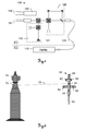
- FIG. 1 shows an optical system 100 of ranging elements with a camera 150 in a prior art laser tracker and a separated HeNe laser light source 110.
- An absolute distance meter 130 with a laser diode 131 and an interferometer 120 are placed together with the camera 150, in particular a zoom camera, in such a way that it moves simultaneously during a movement of the system 100, for example during a pivoting of the entire system 171 carrying the system 100 we will change their orientation together.
- the camera 150 has its own optical system with an optical axis 162, which is substantially parallel to an absolute distance meter 130 and the
- Interferometeran extract 120 common optical axis 161 extends.
- the HeNe laser 110 is attached to a base unit 172, e.g. a support or fixed base, installed separately and we are not moved with the structure 171, but provides the system 100, in particular the interferometer 120, by means of a light guide 109, a generated measuring radiation available.
- a base unit 172 e.g. a support or fixed base, installed separately and we are not moved with the structure 171, but provides the system 100, in particular the interferometer 120, by means of a light guide 109, a generated measuring radiation available.
- a distance to a target can be determined, wherein a precise distance to the target and a distance change can be continuously determined by taking measurements of the interferometer 120 into consideration.
- FIG. 2 shows a laser tracker 70 according to the invention with an image acquisition unit 75 and a measuring auxiliary instrument 80, for example a feeler tool.
- the image capture unit 75 has a CMOS or is designed in particular as a CCD or pixel sensor array camera. Such sensors allow a position-sensitive detection of detected exposure.
- the auxiliary measuring instrument 80 has a sensor whose contact point 83 can be brought into contact with a target object to be measured. While this contact between the stylus 80 and the target object is made, a position of the contact point 83 in the space and thus the coordinates of a point on the target can be accurately determined.
- markers 82 which may be formed for example as light-emitting diodes.
- the markers 82 may also be formed such that they in the case of illumination, eg with radiation of a defined wavelength, which reflects incident radiation (auxiliary point markers 82 designed as retro reflectors), in particular show a specific luminous characteristic, or that these have a defined pattern or color coding. From the position or distribution of the markers 82 in an image captured by the sensor of the image capture unit 75, an orientation of the feeler tool 80 can be determined.
- a measuring laser beam 76 is emitted by the laser tracker 70 in the direction of the reflector 81 arranged on the auxiliary measuring instrument 80, reflected back from there to the tracker 70 in parallel, and detected at the tracker 70 by means of a receiving unit.
- the laser tracker 70 has distance measuring means for determining a distance between the tracker 70 and the reflector 81 and via protractors, which make a position of a beam steering unit, by means of which the laser beam 76 can be aligned and guided defined, and thus a propagation direction of the laser beam 76 determinable.
- the alignment of the laser beam 76 can be effected in particular by pivoting the beam steering unit, in particular a targeting unit, in which a beam-guiding optics and in particular at least one beam source can be installed, or a mirror.
- an absolute distance meter and in particular for determining changes in distance between the tracker 70 and the reflector 81 an interferometer are integrated into the tracker 70.
- the absolute distance meter has a first laser diode for generating a measuring radiation and thus allows a determination of a distance to the target or reflector 81, for example by means of transit time measurement, according to the phase measurement principle or the Fizeau principle.
- the interferometer is provided with a further measuring radiation from a second laser diode. In this case, this measuring radiation can be emitted at the laser diode such that the radiation enters directly into the interferometer or can be guided by means of an optical fiber to the interferometer and coupled into this.
- the second laser diode is configured in such a way that the measuring radiation that can be generated with it is single-mode and has a large coherence length, in particular of at least 10 m, preferably 50 m. For precise distance determination, measurements from both distance measuring means can be used together and linked.
- Advantages for such use of a long coherence length laser diode for an interferometer in a laser tracker 70 are e.g. in the space requirement for the laser diode (which is substantially lower than that for a HeNe gas laser, which is an alternative beam source for it), in the relatively low power consumption, in the rapidly producible measuring beam emission of the diode after activation of the system and the possibility of a high voltage power supply ( eg needed for a HeNe gas laser) to be able to do without.
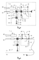
- FIG. 3 shows an inventive arrangement of optical components with a laser diode 20 as a beam source for an interferometer 10 of an optical system 1 in a laser tracker.
- the system 1 has an absolute distance meter 30 (ADM) with a another beam source 31, for example a laser diode or a SLED (superluminescent LED), and a camera 50.
- ADM absolute distance meter
- the light beam emitted by the beam source 31 of the absolute distance meter 30 is passed through an insulator 32 for shielding returning light to a polarizing beam splitter 33 and from there through an electro-optical modulator 34 to a wavelength-dependent beam splitter 41.
- a beam splitter 41 with wavelength-dependent beam splitting is used in particular at different emission wavelengths of the two light sources 20,31.
- the returning light is guided in the absolute distance meter 30 by the polarizing beam splitter 33 to an ADM detector 35.
- other ADM arrangements and methods can be used in this context in which the measurement light beam can be coupled in and out by, for example, the wavelength-dependent beam splitter 41.
- An example of such a distance meter is in the WO 03/062744 Al revealed.
- other types of ADM such as phase meter, can be used.
- the interferometer 10 uses light which is generated by the laser diode 20.
- this diode 20 is arranged directly on the system 1, wherein this generates a longitudinal monomode laser radiation with a large coherence length (single frequency).
- the measurement radiation thus generated is split by a beam splitter 11 into a reference light path 12 and a measurement light path.
- the measuring light path leads through an acousto-optic modulator 13 and, together with the reference light path, hits one polarizing beam splitter 14.
- the polarizing beam splitter 14 passes the measuring radiation to the wavelength-dependent beam splitter 41, and directs the returning measuring light together with the reference light via a polarizing filter 15 to an interferometer detector 16.
- interferometer 10 The operation of such an interferometer 10 is basically known and based on the wave interference principle.
- other interferometer arrangements and methods can also be used in which the measuring radiation can be coupled in and out by, for example, the wavelength-dependent beam splitter 41.
- An example of such an interferometer is in the WO 03/062744 Al described.
- other types of interferometers eg Michelson with quadrature detection
- the optical system 1 further comprises a ⁇ / 4 plate 43 and a component 42, which light, which incident on the outside of the system 1 along a shared by the absolute distance meter 30 and the interferometer 10 optical axis 61, and a first part of this light coupled to an overview camera and a second to a position transducer.
- the overview camera can have its own optics and additionally an image converter.
- the overview camera typically has an aperture angle of approximately 10 ° and a focal length of, for example, 30-50 mm and serves for coarse localization of measurement targets.
- the system may preferably have a reflector illumination with a particular illumination wavelength, which includes a Illuminated angle range, which is preferably at least as large as the opening angle of the overview camera.
- An evaluation electronics and / or evaluation software of the overview camera then detects, for example, one or more bright points of light in the field of view of the overview camera, which each correspond to a reflecting target. From this, their position in the image of the overview camera and, in turn, a change in the orientation of the target, e.g. of a metering aid (e.g., stylus or scanner), whereby the laser tracker or system 1 and light beams of the distance meter (s) 10, 30 can be aligned with the target.
- a metering aid e.g., stylus or scanner
- the light component for the position transducer is typically a beam of returning light emitted by one of the distance meters 10, 30, preferably from the interferometer assembly 10.
- the position transducer may have its own optics and, for example, a position-sensitive diode. This provides signals representing the position of the beam in two dimensions on a surface of the position sensitive diode.
- sensor arrays or image converters eg CCD or CMOS
- a control unit can according to the determined position, an alignment of the laser tracker so that the measuring beam follows a movement of the reflective target.
- the camera can detect 50 markers of a target with the built-in imager. Due to the mapping of the marks, e.g. the orientation of the target is determined by means of image processing, wherein in addition the zoom factor of the camera 50 can be controlled such that the image of the target on the image converter essentially always has the same size.
- the camera 50 may, for example, have a 10x zoom with a focal length of 50 to 500 mm magnification.
- FIG. 4 shows a further embodiment of an inventive measuring optics 1 of a laser tracker with a laser diode 20 as a beam source for an interferometer 10 and a light guide 9.
- the laser diode 20 is in turn provided for generating the measuring radiation for the interferometer 10 of the laser tracker.
- a zoom camera 50 is provided.
- the laser diode 20 is in this case designed such that a measuring radiation with a high coherence length, in particular a coherence length of at least 10 m and a line width of less than 1 MHz, can be generated.
- the laser diode has a wavelength-selective device, for example a periodic structure (optical grating) of the active laser medium, but a grating outside the active medium installed on the same chip or a grating structure in the external fiber 9, which causes the emitted one Laser radiation longitudinally monomode and thus present with a specific narrow line width (single-mode laser).
- the suitable beam characteristic can be determined by means of a highly stable, external cavity or by means of a holographic grid in conjunction with the diode 20 are generated.
- the laser diode 20 according to the embodiment described above, an emission wavelength of 633 nm (visible red spectral range), which is linearly polarized, is single-mode and has a coherence length of at least 10m.
- the emission power of the radiation is above 0.5 mW with a high wavelength stability over the entire service life ( ⁇ 0.3 ppm) of the diode 20.
- the measuring beam can be used simultaneously as a pointing beam, which can be dispensed with an additional beam source for the visual marking of points.
- the radiation generated by the laser diode 20 is coupled by means of the light guide 9 in the interferometer 10.
- a collimator 8 is further provided for connecting the fiber 9 to the interferometer 10.
- the structure of the interferometer 10 is that of the described inventive embodiment according to FIG. 3 similar, wherein the reference path 12 is guided here by means of a steel divider 17 on the detector 16 and the measuring path 18 by means of the steel divider 11.
- the acousto-optic modulator 13 is provided for frequency variation and as an optical isolator.
- the laser tracker on an absolute distance meter 30 with generic typical optical components (beam source, detector, insulator, etc.).
- the laser tracker has two separate units 71, 72.
- the camera 50, the absolute distance meter 30 and the interferometer 10 are arranged on a beam steering unit 71 together with further, in particular, beam-guiding components.
- This beam steering unit 71 may be formed differently depending on the design of the laser tracker, e.g. as a structurally one-piece aiming unit or as a beam guiding unit (e.g., rotatable mirror) having a measuring unit including the absolute distance meter 30 and the interferometer 10.
- the beam steering unit 71 can be designed to be movable, in particular pivotable about two axes, independently of an orientation or orientation of a base unit 72.
- the laser diode 20 embodied as an interferometer beam source can be present in the base unit 72, the radiation generated by the optical fiber 9 coupled into the beam steering unit 71 and the alignment of the beam steering unit 71 and the optical Axes 61,62 of the camera 50 and the distance meter 10,30 relative to the base 72 are changed.
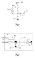
- FIG. 5 shows a basic inventive structure of an interferometer with laser diode 20 for a laser tracker.
- the laser diode is a (longitudinal) single-mode measuring radiation with a Coherence length of at least 10m, preferably 50m, generated, which is performed with beam splitters on the one hand on a reference path 12 and the other on a return path 19.
- the radiation is directed to a reflective target 25 and reflected there.
- an acousto-optic modulator 13 is arranged in the return path 19.
- the target 25 represents a movable target 25, wherein a change in distance to the interferometer by means of the interferometer detector 16 can be detected and measured.
- the reference radiation and the measuring radiation are superimposed on the interferometer detector 16, as a result of which these beams interfere and permit reading of measured values.
- FIG. 6 1 shows a further embodiment of a measuring optics 1 according to the invention of a laser tracker with a laser diode 20 as an interferometer beam source for generating a measuring radiation for an interferometer 10 with a wavelength stabilizing unit 21.
- an absolute distance meter 30 with a further light source 31, preferably embodied as a laser diode or SLED, and a camera 50 is provided.
- the wavelength stabilization unit 21 By means of the wavelength stabilization unit 21, a stabilization of the measurement radiation to a wavelength standard, for example to an absorption line (eg using an iodine cell) of approximately 633 nm, is realized.
- the wavelength stabilization unit 21 may have stabilization via a gas cell.
- different stabilization approaches can be used for stabilization, such as synchronous detection ("synchronous detection”: modulation of the optical frequency about a central absorption line), “side-of-line” method or Stabilization by means of the Zeeman effect at constant optical frequency (with magnetic modulation).
- the "side of line” method is based on a stabilization by absorption at an absorption value, which corresponds to the maximum slope of a corresponding absorption line of a gas cell (eg stabilization at about 40% absorption).
- the laser diode 20 For such a stabilization, light with a modehop-free tunable wavelength range is provided by the laser diode 20, so that it is possible to tune the wavelength to the desired absorption line.
- the generated laser light also has a large coherence length (at least 10m, especially 50m).
- FIG. 7 shows a further embodiment of an inventive measuring optics 1 of a laser tracker with a laser diode 20 for generating a measuring radiation for an interferometer 10, a wavelength stabilization unit 21 and optical fibers 9a, 9b for guiding the laser radiation.
- the single-mode laser radiation generated by the diode 20 is guided to the wavelength stabilization unit 21 by means of the optical fiber 9a.
- This stabilization unit 21 effects a largely constant holding of the wavelength of the laser radiation.
- the thus stabilized radiation is guided by another optical fiber 9b from the wavelength stabilization unit 21 to the interferometer 10. Due to the thus generated measuring radiation having a large coherence length and wavelength stability, measurements of distance changes with the interferometer 10 can be carried out with high precision.
- a spatial and in particular structural separation of the laser diode 20 and the wavelength stabilization unit 21 is achieved by the distance measuring means 10,30 and the camera 50 of the laser tracker by connecting the two units 71,72 by means of the optical fiber 9b.
Landscapes
- Physics & Mathematics (AREA)
- General Physics & Mathematics (AREA)
- Engineering & Computer Science (AREA)
- Radar, Positioning & Navigation (AREA)
- Remote Sensing (AREA)
- Electromagnetism (AREA)
- Computer Networks & Wireless Communication (AREA)
- Length Measuring Devices By Optical Means (AREA)
- Optical Radar Systems And Details Thereof (AREA)
- Instruments For Measurement Of Length By Optical Means (AREA)
- Semiconductor Lasers (AREA)
Priority Applications (7)
| Application Number | Priority Date | Filing Date | Title |
|---|---|---|---|
| EP11187614.0A EP2589982A1 (fr) | 2011-11-03 | 2011-11-03 | Diode laser comme source de rayonnement laser d'interféromètre dans un appareil de suivi laser |
| KR1020147012835A KR101629760B1 (ko) | 2011-11-03 | 2012-11-02 | 레이저 트래커에서 간섭계-레이저 빔 소스로서의 레이저 다이오드 |
| PCT/EP2012/071708 WO2013064625A1 (fr) | 2011-11-03 | 2012-11-02 | Diode laser comme source de rayonnement laser d'interféromètre dans un tracker à laser |
| JP2014540405A JP2015501437A (ja) | 2011-11-03 | 2012-11-02 | レーザトラッカにおいて干渉計レーザビーム源として設置されるレーザダイオード |
| CN201280053691.0A CN103930796B (zh) | 2011-11-03 | 2012-11-02 | 作为激光追踪器中的干涉仪激光束源的激光二极管 |
| US14/356,119 US9400175B2 (en) | 2011-11-03 | 2012-11-02 | Laser diode as interferometer-laser beam source in a laser tracker |
| EP12780746.9A EP2773980B1 (fr) | 2011-11-03 | 2012-11-02 | Diode laser comme source de rayonnement laser d'interféromètre dans un appareil de suivi laser |
Applications Claiming Priority (1)
| Application Number | Priority Date | Filing Date | Title |
|---|---|---|---|
| EP11187614.0A EP2589982A1 (fr) | 2011-11-03 | 2011-11-03 | Diode laser comme source de rayonnement laser d'interféromètre dans un appareil de suivi laser |
Publications (1)
| Publication Number | Publication Date |
|---|---|
| EP2589982A1 true EP2589982A1 (fr) | 2013-05-08 |
Family
ID=47115990
Family Applications (2)
| Application Number | Title | Priority Date | Filing Date |
|---|---|---|---|
| EP11187614.0A Withdrawn EP2589982A1 (fr) | 2011-11-03 | 2011-11-03 | Diode laser comme source de rayonnement laser d'interféromètre dans un appareil de suivi laser |
| EP12780746.9A Active EP2773980B1 (fr) | 2011-11-03 | 2012-11-02 | Diode laser comme source de rayonnement laser d'interféromètre dans un appareil de suivi laser |
Family Applications After (1)
| Application Number | Title | Priority Date | Filing Date |
|---|---|---|---|
| EP12780746.9A Active EP2773980B1 (fr) | 2011-11-03 | 2012-11-02 | Diode laser comme source de rayonnement laser d'interféromètre dans un appareil de suivi laser |
Country Status (6)
| Country | Link |
|---|---|
| US (1) | US9400175B2 (fr) |
| EP (2) | EP2589982A1 (fr) |
| JP (1) | JP2015501437A (fr) |
| KR (1) | KR101629760B1 (fr) |
| CN (1) | CN103930796B (fr) |
| WO (1) | WO2013064625A1 (fr) |
Cited By (7)
| Publication number | Priority date | Publication date | Assignee | Title |
|---|---|---|---|---|
| EP2998764A1 (fr) * | 2014-09-22 | 2016-03-23 | Andreas Enders | Procédé destiné à tracer des points de mesure |
| US9310178B2 (en) | 2013-06-18 | 2016-04-12 | Hexagon Technology Center Gmbh | Interferometric determination of distance change with laser diode, high bandwidth detection and fast signal processing |
| EP3032277A1 (fr) * | 2014-12-12 | 2016-06-15 | Leica Geosystems AG | Appareil de suivi laser |
| US9645239B2 (en) | 2012-05-07 | 2017-05-09 | Leica Geosystems Ag | Laser tracker comprising interferometer and absolute distance measuring unit, and calibration method for a laser tracker |
| EP3179271A1 (fr) | 2015-12-11 | 2017-06-14 | Leica Geosystems AG | Module tec comprenant une diode laser comme source de rayonnement laser d'interféromètre dans un appareil de suivi laser |
| EP3220163A1 (fr) * | 2016-03-15 | 2017-09-20 | Leica Geosystems AG | Appareil de suivi laser a deux fonctionnalites de mesure |
| US10338219B2 (en) | 2012-05-07 | 2019-07-02 | Leica Geosystems Ag | Measuring apparatus comprising an interferometer and an absorption medium defining a dense line spectrum |
Families Citing this family (11)
| Publication number | Priority date | Publication date | Assignee | Title |
|---|---|---|---|---|
| WO2016195502A1 (fr) * | 2015-06-04 | 2016-12-08 | Conoptica As | Système de recherche de position d'espace libre |
| JP6849371B2 (ja) | 2015-10-08 | 2021-03-24 | 三星電子株式会社Samsung Electronics Co.,Ltd. | 側面発光レーザ光源、及びそれを含む三次元映像取得装置 |
| CN107884762A (zh) * | 2016-09-30 | 2018-04-06 | 比亚迪股份有限公司 | 激光雷达及车辆 |
| CN110036256B (zh) * | 2016-12-12 | 2020-10-27 | 国立研究开发法人产业技术综合研究所 | 标记器和标记器的制造方法 |
| US10883816B2 (en) | 2017-03-22 | 2021-01-05 | Asml Netherlands B.V. | Position measurement system, zeroing method, lithographic apparatus and device manufacturing method |
| KR20190060022A (ko) | 2017-11-23 | 2019-06-03 | 삼성디스플레이 주식회사 | 레이저용 시어링 간섭계 |
| KR102474591B1 (ko) | 2018-01-24 | 2022-12-05 | 삼성전자주식회사 | 광 조향 장치 및 이를 포함하는 센서 시스템 |
| TWI665461B (zh) * | 2018-05-04 | 2019-07-11 | 財團法人工業技術研究院 | 雷射定位系統及使用此系統之位置量測方法 |
| CN109520425B (zh) * | 2018-12-29 | 2020-12-01 | 湖北航天技术研究院总体设计所 | 一种精跟踪误差测试装置及测试方法 |
| CN109764806B (zh) * | 2019-01-04 | 2021-01-19 | 西安交通大学 | 用于激光跟踪仪的动静态校准装置及动、静态校准方法 |
| TWI701423B (zh) * | 2019-07-01 | 2020-08-11 | 東元電機股份有限公司 | 反射貼紙輔助定位系統 |
Citations (8)
| Publication number | Priority date | Publication date | Assignee | Title |
|---|---|---|---|---|
| US5114226A (en) * | 1987-03-20 | 1992-05-19 | Digital Optronics Corporation | 3-Dimensional vision system utilizing coherent optical detection |
| EP0553266A1 (fr) | 1990-10-15 | 1993-08-04 | Waldean A Schulz | Procede et appareil de detection sans contact de formes tridimensionnelles. |
| US5473428A (en) * | 1993-12-31 | 1995-12-05 | Samsung Electronics Co., Ltd. | Interferometric temperature sensing system having a coupled laser diode wherein the magnitude is adjusted corresponding to a prior feed-back laser beam |
| JP2002039714A (ja) * | 2000-07-25 | 2002-02-06 | Yokogawa Electric Corp | 位置検出装置 |
| WO2003062744A1 (fr) | 2002-01-16 | 2003-07-31 | Faro Technologies, Inc. | Dispositif et procede de mesure de coordonnees par laser |
| DE10235669A1 (de) * | 2002-08-03 | 2004-02-12 | Dr. Johannes Heidenhain Gmbh | Positionsmesseinrichtung |
| EP1655582A2 (fr) * | 2004-11-03 | 2006-05-10 | Dr. Johannes Heidenhain GmbH | Système de mesure de position |
| WO2007079600A1 (fr) | 2006-01-13 | 2007-07-19 | Leica Geosystems Ag | Appareil de mesure de coordonnées |
Family Cites Families (6)
| Publication number | Priority date | Publication date | Assignee | Title |
|---|---|---|---|---|
| DE3528259A1 (de) * | 1985-08-07 | 1987-02-19 | Adolf Friedrich Prof D Fercher | Verfahren und anordnung zur interferometrischen laengenmessung mit halbleiterlasern als lichtquelle |
| DE3886966T2 (de) * | 1987-03-20 | 1994-08-18 | Digital Optronics Corp | Bildsystem in drei Dimensionen mit kohärenter optischer Detektion. |
| JPH05312523A (ja) * | 1992-05-06 | 1993-11-22 | Olympus Optical Co Ltd | 半導体レーザ測長器 |
| EP1517415A1 (fr) | 2003-09-18 | 2005-03-23 | Leica Geosystems AG | Appareil géodésique comprenant une source laser |
| JP2007114141A (ja) * | 2005-10-24 | 2007-05-10 | Ono Sokki Co Ltd | レーザ測定装置 |
| ES2539119T3 (es) * | 2007-10-09 | 2015-06-26 | Windar Photonics A/S | Sistema LIDAR coherente basado en láser y amplificador semiconductor |
-
2011
- 2011-11-03 EP EP11187614.0A patent/EP2589982A1/fr not_active Withdrawn
-
2012
- 2012-11-02 EP EP12780746.9A patent/EP2773980B1/fr active Active
- 2012-11-02 US US14/356,119 patent/US9400175B2/en active Active
- 2012-11-02 WO PCT/EP2012/071708 patent/WO2013064625A1/fr active Application Filing
- 2012-11-02 KR KR1020147012835A patent/KR101629760B1/ko active IP Right Grant
- 2012-11-02 CN CN201280053691.0A patent/CN103930796B/zh active Active
- 2012-11-02 JP JP2014540405A patent/JP2015501437A/ja active Pending
Patent Citations (9)
| Publication number | Priority date | Publication date | Assignee | Title |
|---|---|---|---|---|
| US5114226A (en) * | 1987-03-20 | 1992-05-19 | Digital Optronics Corporation | 3-Dimensional vision system utilizing coherent optical detection |
| EP0553266A1 (fr) | 1990-10-15 | 1993-08-04 | Waldean A Schulz | Procede et appareil de detection sans contact de formes tridimensionnelles. |
| US5473428A (en) * | 1993-12-31 | 1995-12-05 | Samsung Electronics Co., Ltd. | Interferometric temperature sensing system having a coupled laser diode wherein the magnitude is adjusted corresponding to a prior feed-back laser beam |
| JP2002039714A (ja) * | 2000-07-25 | 2002-02-06 | Yokogawa Electric Corp | 位置検出装置 |
| WO2003062744A1 (fr) | 2002-01-16 | 2003-07-31 | Faro Technologies, Inc. | Dispositif et procede de mesure de coordonnees par laser |
| DE10235669A1 (de) * | 2002-08-03 | 2004-02-12 | Dr. Johannes Heidenhain Gmbh | Positionsmesseinrichtung |
| EP1655582A2 (fr) * | 2004-11-03 | 2006-05-10 | Dr. Johannes Heidenhain GmbH | Système de mesure de position |
| WO2007079600A1 (fr) | 2006-01-13 | 2007-07-19 | Leica Geosystems Ag | Appareil de mesure de coordonnées |
| EP2261601A1 (fr) * | 2006-01-13 | 2010-12-15 | Leica Geosystems AG | Dispositif de mesure de coordonnées |
Cited By (13)
| Publication number | Priority date | Publication date | Assignee | Title |
|---|---|---|---|---|
| US9645239B2 (en) | 2012-05-07 | 2017-05-09 | Leica Geosystems Ag | Laser tracker comprising interferometer and absolute distance measuring unit, and calibration method for a laser tracker |
| US10338219B2 (en) | 2012-05-07 | 2019-07-02 | Leica Geosystems Ag | Measuring apparatus comprising an interferometer and an absorption medium defining a dense line spectrum |
| US11067690B2 (en) | 2012-05-07 | 2021-07-20 | Leica Geosystems Ag | Measuring apparatus comprising an interferometer and an absorption medium defining a dense line spectrum |
| US9310178B2 (en) | 2013-06-18 | 2016-04-12 | Hexagon Technology Center Gmbh | Interferometric determination of distance change with laser diode, high bandwidth detection and fast signal processing |
| EP2998764A1 (fr) * | 2014-09-22 | 2016-03-23 | Andreas Enders | Procédé destiné à tracer des points de mesure |
| US10725179B2 (en) | 2014-12-12 | 2020-07-28 | Leica Geosystems Ag | Laser tracker |
| EP3032277A1 (fr) * | 2014-12-12 | 2016-06-15 | Leica Geosystems AG | Appareil de suivi laser |
| CN105699983A (zh) * | 2014-12-12 | 2016-06-22 | 莱卡地球系统公开股份有限公司 | 激光跟踪器 |
| CN105699983B (zh) * | 2014-12-12 | 2019-07-09 | 莱卡地球系统公开股份有限公司 | 激光跟踪器、提供附加测量功能的方法以及计算机可读存储介质 |
| EP3179271A1 (fr) | 2015-12-11 | 2017-06-14 | Leica Geosystems AG | Module tec comprenant une diode laser comme source de rayonnement laser d'interféromètre dans un appareil de suivi laser |
| US10627211B2 (en) | 2015-12-11 | 2020-04-21 | Leica Geosystems Ag | TEC module having laser diode as an interferometer laser beam source in a laser tracker |
| EP3220163A1 (fr) * | 2016-03-15 | 2017-09-20 | Leica Geosystems AG | Appareil de suivi laser a deux fonctionnalites de mesure |
| US10444361B2 (en) | 2016-03-15 | 2019-10-15 | Leica Geosystems Ag | Laser tracker having two measurement functionalities |
Also Published As
| Publication number | Publication date |
|---|---|
| US20140307264A1 (en) | 2014-10-16 |
| CN103930796B (zh) | 2018-02-02 |
| EP2773980A1 (fr) | 2014-09-10 |
| JP2015501437A (ja) | 2015-01-15 |
| EP2773980B1 (fr) | 2019-06-26 |
| CN103930796A (zh) | 2014-07-16 |
| US9400175B2 (en) | 2016-07-26 |
| KR20140085507A (ko) | 2014-07-07 |
| WO2013064625A1 (fr) | 2013-05-10 |
| KR101629760B1 (ko) | 2016-06-13 |
Similar Documents
| Publication | Publication Date | Title |
|---|---|---|
| EP2773980B1 (fr) | Diode laser comme source de rayonnement laser d'interféromètre dans un appareil de suivi laser | |
| EP2847613B1 (fr) | Appareil de suivi laser doté d'un interféromètre et unité de mesure de distance absolue ainsi que procédé de calibrage pour un appareil de suivi laser | |
| EP3220163B1 (fr) | Appareil de suivi laser à deux fonctionnalités de mesure | |
| EP1971821B1 (fr) | Appareil de mesure de coordonnees | |
| EP2980526B1 (fr) | Appareil et méthode de mesure de coordonnées | |
| EP2847538B1 (fr) | Appareil de mesure comportant un interféromètre et un milieu d'absorption dense définissant un spectre de raies | |
| EP2875383B1 (fr) | Appareil de suivi laser avec unité de calibrage pour calibrage automatique | |
| EP2801841B1 (fr) | Appareil de suivi laser comprenant une unité d'enregistrement d'une cible pour le pistage d'une cible et une détection d'orientation | |
| EP3032277B1 (fr) | Appareil de suivi laser | |
| EP2446299B1 (fr) | Appareil de mesure de coordonnées | |
| EP2558880B1 (fr) | Appareil de mesure de coordonnées doté d'une détection de cible automatique | |
| EP3179271B1 (fr) | Module tec comprenant une diode laser comme source de rayonnement laser d'interféromètre dans un appareil de suivi laser | |
| DE102004037137B4 (de) | Verfahren und Vorrichtung zur Entfernungsmessung | |
| EP2602641A1 (fr) | Appareil de suivi laser doté de détecteurs sensibles à la position pour la recherche d'une cible | |
| EP2820444A1 (fr) | Procédé pour déterminer une variation de distance par interférométrie | |
| DE102014004697B4 (de) | System und Verfahren zur Distanzmessung | |
| CH706633B1 (de) | Lasertracker und Verfahren zur Wellenlängenstabilisierung eines Gaslasers eines Lasertrackers. | |
| EP4298459A1 (fr) | Dispositif de poursuite laser à deux fonctionnalités de mesure et mesure de distance fmcw | |
| DE102020202982A1 (de) | Optische Vorrichtung zur Abstandsbestimmung eines Messobjekts | |
| WO2021228959A1 (fr) | Procédé et système destinés à mesurer une topographie de surface d'un objet |
Legal Events
| Date | Code | Title | Description |
|---|---|---|---|
| PUAI | Public reference made under article 153(3) epc to a published international application that has entered the european phase |
Free format text: ORIGINAL CODE: 0009012 |
|
| AK | Designated contracting states |
Kind code of ref document: A1 Designated state(s): AL AT BE BG CH CY CZ DE DK EE ES FI FR GB GR HR HU IE IS IT LI LT LU LV MC MK MT NL NO PL PT RO RS SE SI SK SM TR |
|
| AX | Request for extension of the european patent |
Extension state: BA ME |
|
| STAA | Information on the status of an ep patent application or granted ep patent |
Free format text: STATUS: THE APPLICATION IS DEEMED TO BE WITHDRAWN |
|
| 18D | Application deemed to be withdrawn |
Effective date: 20131109 |