EP3220034A1 - Female element for a fluid coupling and fluid coupling including such an element - Google Patents
Female element for a fluid coupling and fluid coupling including such an element Download PDFInfo
- Publication number
- EP3220034A1 EP3220034A1 EP17160476.2A EP17160476A EP3220034A1 EP 3220034 A1 EP3220034 A1 EP 3220034A1 EP 17160476 A EP17160476 A EP 17160476A EP 3220034 A1 EP3220034 A1 EP 3220034A1
- Authority
- EP
- European Patent Office
- Prior art keywords
- wall
- longitudinal axis
- locking
- connecting element
- seal
- Prior art date
- Legal status (The legal status is an assumption and is not a legal conclusion. Google has not performed a legal analysis and makes no representation as to the accuracy of the status listed.)
- Granted
Links
Images


Classifications
-
- F—MECHANICAL ENGINEERING; LIGHTING; HEATING; WEAPONS; BLASTING
- F16—ENGINEERING ELEMENTS AND UNITS; GENERAL MEASURES FOR PRODUCING AND MAINTAINING EFFECTIVE FUNCTIONING OF MACHINES OR INSTALLATIONS; THERMAL INSULATION IN GENERAL
- F16L—PIPES; JOINTS OR FITTINGS FOR PIPES; SUPPORTS FOR PIPES, CABLES OR PROTECTIVE TUBING; MEANS FOR THERMAL INSULATION IN GENERAL
- F16L37/00—Couplings of the quick-acting type
- F16L37/22—Couplings of the quick-acting type in which the connection is maintained by means of balls, rollers or helical springs under radial pressure between the parts
- F16L37/23—Couplings of the quick-acting type in which the connection is maintained by means of balls, rollers or helical springs under radial pressure between the parts by means of balls
-
- F—MECHANICAL ENGINEERING; LIGHTING; HEATING; WEAPONS; BLASTING
- F16—ENGINEERING ELEMENTS AND UNITS; GENERAL MEASURES FOR PRODUCING AND MAINTAINING EFFECTIVE FUNCTIONING OF MACHINES OR INSTALLATIONS; THERMAL INSULATION IN GENERAL
- F16L—PIPES; JOINTS OR FITTINGS FOR PIPES; SUPPORTS FOR PIPES, CABLES OR PROTECTIVE TUBING; MEANS FOR THERMAL INSULATION IN GENERAL
- F16L21/00—Joints with sleeve or socket
- F16L21/02—Joints with sleeve or socket with elastic sealing rings between pipe and sleeve or between pipe and socket, e.g. with rolling or other prefabricated profiled rings
- F16L21/03—Joints with sleeve or socket with elastic sealing rings between pipe and sleeve or between pipe and socket, e.g. with rolling or other prefabricated profiled rings placed in the socket before connection
Definitions
- the invention relates to a fluidic connection element for constituting, with a complementary nozzle, a connector for connecting fluid circulation ducts.
- the invention is more particularly intended to provide by proposing a new fluidic coupling element that is compatible with a clamp type nozzle and that makes it possible to provide a tight and long-lasting connection with such a tip.
- the invention relates to a coupling element adapted to be coupled with a complementary end piece for joining the two fluid lines, this coupling element comprising a partial receiving body of the complementary endpiece, this body being centered on a longitudinal axis and defining, on the one hand, a fluid circulation channel within the body and, on the other hand, a sealing chamber which surrounds the channel and in which is housed a seal able to cooperate with the complementary nozzle introduced into the body, the sealing chamber being delimited by an outer radial wall, a front wall, a rear wall and, radially inwardly with respect to the longitudinal axis, by an internal radial wall solidary of the body.
- This coupling element comprises a locking mechanism which comprises, on the one hand, locking members movable radially in this body relative to the longitudinal axis, between a locking position of the complementary endpiece in the body and a position releasing a passage of the nozzle into the body and, secondly, a locking ring mounted around the body and movable relative thereto, between a first position for holding the locking members in their position locking and a second position in which the locking ring is not opposed to the displacement of the locking members to the release position.
- the front edge of the inner radial wall is recessed, along the longitudinal axis, with respect to the rear surface of the front wall.
- the invention relates to a coupling which comprises a coupling element and a complementary endpiece.
- the complementary end piece is provided with a central fluid passage channel, an external radial cavity for receiving at least one locking member in a configuration coupled with the coupling, the receiving cavity being delimited at the front by a flange, a front face and a circumferential groove which borders the front face, which is arranged radially between the central channel and the circumferential groove.
- the coupling element is as mentioned above, whereas, in the coupled configuration of the coupling, the inner wall of the sealing chamber is aligned along the longitudinal axis of the coupling element. with the front side of the complementary tip.
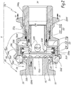
- the fluidic connection R shown in Figures 1 to 4 comprises female element 200 intended to be coupled with a male end 100 complementary to this female element.
- the male endpiece 100 is of the type end clamp as defined by the standards DIN-32676 or ASME BPE-2007 for an endpiece of outside diameter flange equal to 25 mm.
- DIN-32676 or ASME BPE-2007 for an endpiece of outside diameter flange equal to 25 mm.
- flange OD for a flange OD of 34, 50 or 64 mm, this is defined by ISO 2852, DIN 32676, BS 4825-3 and / or ASME BPE-2007.
- This male endpiece 100 comprises a one-piece body 102, preferably made of metal, which defines a central channel 104 for fluid circulation, which channel is connected, in a manner known per se and on the rear of the body 102, to a C1 pipe of fluid circulation. For the clarity of the drawing, this pipe is shown between dashed lines only at the figure 1 .
- the tip 100 is centered on a longitudinal axis X1 which constitutes an axis of symmetry for the body 102.
- the channel 104 is cylindrical with a circular section centered on the axis X1.
- the body 102 On its outer radial surface, the body 102 is provided with a peripheral groove 106 which constitutes an external cavity for receiving a locking means.
- This locking means may be a wall of a collar, as known in the state of the art, or balls of the female element, as is apparent from the explanations that follow.
- the groove 106 is delimited, axially along the axis X1, forwardly by a flange 108 and rearwardly by a collar 110, this flange being optional insofar as the body 102 can retain the reduced diameter of the bottom of the groove 106 towards the rear of the male end 100.
- the front side of a nozzle or element of the coupling R is defined as the side of this nozzle or element oriented in the direction of fitting or coupling, that is to say oriented towards the 'element or the complementary coupling end during fitting.
- the rear side of a tip or element of the coupling R is defined as the direction opposite to the element or the complementary coupling piece. So, in the example of Figures 1 to 4 , the front of the male end 100 is located on the right of this tip, while the front of the female member 200 is located on the left of this tip.
- 1082 is the front edge of the flange 108, 1084 its outer radial surface and 1086 a joining bevel between the edge 1082 and the surface 1084.
- the male endpiece 100 is provided with a front face 112 which is recessed rearwardly with respect to the front edge 1082 of the flange 108.
- This front face is bordered on the outside by a circumferential groove 114 which is intended to receive part of a seal when this tip 100 is used in a conventional manner, in cooperation with a similar-shaped tip and with a collar.
- the front face 112 is disposed, radially to the axis X1, between the central channel 104 and the circumferential groove 114.
- the front face 112 and the groove 114 are made in the form of a countersink from the before the male endpiece 100.
- the female element 200 is centered on a longitudinal axis X2 and comprises a body 202 intended to receive a front portion of the male endpiece 100 in a coupled configuration of the connector R.
- the body 202 is formed of a monoblock front part 2022 and a one-piece rear portion 2024 screwed onto the front part, with the interposition of an O-ring seal 2026.
- the parts 2022 and 2024 are made of metal, preferably steel.
- the body 202 defines a central channel 204 for fluid passage.
- This central channel 204 is formed by two central unit channels 2042 and 2044 respectively formed in the center of a rear portion of the front portion 2022 and in the center of the rear portion 2024 of the body 202.
- This channel 204 is connected on the rear of the body 202, to a fluid circulation pipe C2 which is shown in phantom only at the figure 1 , for the sake of clarity.
- a locking mechanism 206 is provided on the female member 200 and comprises a row of balls 2062 disposed in radial through-holes 2064 in the body 202, near its leading edge 2021.
- the orifices 2064 are through in that they open at the same time on an internal radial surface 202s and on an external radial surface 202t of the body 202.
- the outlet of each orifice 2064 on the internal radial surface 202s of the body 202 has a diameter smaller than that of the balls 2062, which allows to limit a centripetal movement of the balls 2062 in the direction of the axis X2.
- the mechanism 206 also comprises a locking ring 2066, which is slidably mounted around the body 202, and a spring 2068 which exerts on this an elastic axial force E2 directed towards the front of the female element 200.
- the spring 2068 is a spiral compression spring disposed radially between the body 202 and the ring 2066, bearing against an external shoulder 202e of the body 202 and against an internal shoulder 2066e of the locking ring 2066.
- the body 202 On the side of its front edge 2021, the body 202 has a greater external diameter than in its part around which is mounted the spring 2068.
- This surface 2066s has a diameter substantially equal to the outer diameter of the outer radial surface 202t of the front portion of the body 202, so that when this surface 2066s is opposite, along the axis X2, with the balls 2062 it forces said balls to protrude radially inwards with respect to the internal radial surface 202s of the body 202, through the respective outlets of the orifices 2064.
- the ring 2066 In the vicinity of its front edge 2066b, the ring 2066 is provided with a diverging portion 2066d whose inner surface defines a chamfer 2066c converging towards the longitudinal axis X2 away from the front edge 2066b. There is thus formed a hollow volume V between the chamfer 2066c and the outer radial surface 202t of the body 202 at the orifices 2064.
- the locking ring 2066 is provided with an outer peripheral flange 2066f on which an operator can exert an axial force E4 parallel to the axis X2 and directed rearwards, greater than the force E2, so that to bring the volume V opposite balls 2062 when necessary, as explained below.
- the element 200 further defines a sealing chamber 208 in which is disposed a seal 210 of elastomer.
- the sealing chamber radially surrounds the unit channel 2042 formed in the front portion 2022 of the body 202.
- This sealing chamber is delimited radially to the axis X2 between an outer radial wall 2082 and an inner radial wall 2084 which is provided with four openings 2085 communicating the channel 204 with the sealing chamber 208.
- the sealing chamber 208 is defined between a front wall 2086 and a rear wall 2088 which connects the two parts of different diameter of the body 202 mentioned above.
- the walls 2082, 2084, 2086 and 2088 form a single piece. These are portions of the front portion 2022 of the body 202.
- the wall 2084 is integral with the body 202, insofar as it is fixed relative to the body in uncoupled configuration and being mated.
- the inner radial wall 2084 delimits the front portion of the channel 2042 and is radially disposed between the longitudinal axis X2 and the sealing chamber 208.
- the walls 2082, 2084, 2086 and 2088 respectively define radial internal 2082s, radial outer 2084s, axial rear 2086s and axial front 2088s faces facing the sealing chamber 208 and which form contours of the sealing chamber 208.
- the sealing chamber 208 is disposed at the rear of the housing 2064 and the housing 2064 are formed in the front wall 2086.
- the sealing chamber 208 forms an annular volume around the axis X2 within the body 202.
- the locking ring 2066 Under the force E2 of the spring 2068, in uncoupled configuration, the locking ring 2066 abuts against the outer surface 2088t of the wall 2088 which is opposite to the sealing chamber 208.
- the outer radial wall 2082 constitutes the bottom of the the sealing chamber 208.
- the rear axial surface 2086s of the front wall 2086 extends radially, from the outer radial wall 2082 and towards the longitudinal axis X2, over a radial height less than the radial dimension of the surface. before 2088s of the rear wall 2088.
- the sealing chamber 208 is closed on the rear side of the female member 200, but partially open towards the front edge 2021. Specifically the sealing chamber 208 is open along the longitudinal axis X2 towards the mouth of the connecting element 200.
- the front edge 2084b is the front edge of the inner radial wall 2084 which is directed towards the front of the female element 200. This front edge is intended to bear against the front face 112 of the male endpiece 100 being fitting of the elements 100 and 200 into each other and possibly into the coupled configuration of the connector R.
- the front edge 2084b is a surface perpendicular to the axis X2.
- the inner radial surface 2082s of the outer radial wall 2082 extends between the rear wall 2088 and the front wall 2086 over an axial length L2082 greater than the axial length L2084 of the inner radial wall 2084.
- the axial length L2084 of the inner radial wall 2084 is between 50% and 90%, preferably of the order of 75%, of the axial length.
- the sealing chamber 208 is closed on the outer side of the female element 200, but partially open radially inward towards the longitudinal axis X2.
- the front edge 2084b of the inner radial wall 2084 is recessed, along the axis X2, with respect to the rear axial surface 2086s.
- an axial distance d1 measured parallel to the axis X2, between the rear axial surface 2086s and the front edge 2084b, is non-zero and the rear axial surface 2086s is disposed further forward than the front edge 2084b along the X2 axis.
- the seal 210 has a geometry of revolution about an axis coincident with the axis X2 in the mounted configuration of the seal 210 in the sealing chamber 208.
- the section of the seal 210 is, in the plane of Figures 1 to 4 which is a plane radial to the axis X2, generally U-shaped open towards the longitudinal axis X2.
- the seal 210 comprises an annular outer base 2102 and two branches formed respectively by a front blade 2104 and a rear blade 2106.
- the base 2102 comprises a plane outer surface adapted to come into contact with the inner radial surface 2082s and a rear surface adapted to come in contact with the surface before 2088s.
- the seal 210 is symmetrical with respect to a plane P perpendicular to the axis X2 and passing through the center of the base 2102.
- the front blade 2104 extends from the front portion of the base 2102 both toward the longitudinal axis X2 and in a direction directed rearwardly of the female member 200
- the rear blade 2106 extends from the rear portion of the base 2102 both toward the longitudinal axis X2 and in a forward direction of the female member 200.
- the root of the blade before 2104 that is to say its junction area with the base 2102 is disposed along the axis X2, generally facing a portion X2P of the axis X2 located between the rear axial surface 2086s and the edge before 2084b, that is to say between the front wall 2086 and the front end of the inner radial wall 2084.
- the front blade 2104 protrudes radially from the front wall 2086 towards the longitudinal axis X2 at level of a portion of the longitudinal axis X2 disposed forward of the front edge 2084b.
- the blades 2104 and 2106 converge in the direction of the plane P away from the base 2102. Note the angle of convergence of the blades 2104 and 2106 towards each other.
- each of the blades 2104 and 2106 forms a curved finger inclined in the direction of the plane P which is perpendicular to the base 2102.
- the front blade 2104 forms with the base 2102 an acute angle ⁇ , whose value is between 65 ° and 80 °, preferably of the order of 75 °.
- the dimensions of the seal 210 are defined according to those of the sealing chamber 208, so that when it is in place in the sealing chamber 208, the seal 210 bears by its base 2102 against the outer radial wall 2082 which constitutes the bottom of the sealing chamber 208.
- the front blade 2104 protrudes radially, in the direction of the longitudinal axis X2, with respect to the front wall 2086, over a radial height H2 corresponds to approximately half of the radial height H2086 of the rear axial surface 2086s.
- the front blade 2104 of the seal 210 is accessible for the tip 100 from the mouth of the female element 200.
- the ratio H2 / H2086 can be chosen between 30% and 70%, preferably between 40% and 60%.
- D2 is the radial distance between the inner radial edge of the front wall 2086, corresponding to the surface 202s, and the outer radial surface 2084s of the wall 2084. This distance d2 is greater than the radial height H210 of the seal 210, which allows to introduce the seal 210 in the sealing chamber 208 by the front of the female element 200.
- the radial opening between the walls 2084 and 2086, of radial height d2 also makes it easy to remove the seal 210, in particular for a complete cleaning operation of the female element 200.
- the axes X1 and X2 are aligned and together define a central axis XR of the connection R.
- the operator moves the ring 2066 against the effort elastic E2 exerted by the spring 2068 by exerting on the collar 2066f a force E4 directed towards the rear of the female element 200.
- This effort E4 is maintained until the locking ring 2066 comes to rest by a shoulder 2066g against a corresponding external shoulder 202g formed on the body 202, more precisely on its rear portion 2024. It then reaches the configuration of the figure 2 where the volume V is facing axially, along the axis XR, with a portion of the balls 2062.
- the male endpiece 100 into the mouth of the female element 200 defined by the inner radial surface 202s.
- the flange 108 pushes the balls 2062 radially outwards, within the orifices 2064, which is possible because the surface 2066s no longer opposes this centrifugal radial displacement of the balls 2062.
- the balls 2062 reach thus a second position different from the first position represented in figure 1 and wherein they are partially received in the volume V and release a passage for the tip 100 in the body 202.
- the locking ring 2066 When the operator releases his force E4 on the flange 2066f, the locking ring 2066 is pushed towards the front of the female element 200 by the force E2 of the spring 2068, which has the effect of realigning the surface 2066s axially. with the balls 2062.
- the convergent character of the chamfer 2066c in the direction of the axis XR and to the rear of the female element 200 facilitates the centripetal movement of the balls 2062 because this chamfer operates as a ball return ramp 2062 to the XR axis.
- the surface 2066s radially surrounds the locking balls 2062 and holds them in their first position, where they project towards the axis XR with respect to the surface 202s.
- the balls 2062 are thus kept engaged in the groove 106, which has the effect of blocking the male endpiece 100 in the body 202 of the female element 200. In this configuration shown in FIG.
- the male endpiece 100 is locked in the body 202, in that it can not be removed from this body, in a spacing movement of the elements 100 and 200 along the axis XR, even if a Relative rotation movement around the axis XR remains possible between the endpiece 100 and the female element 200.
- the balls 2062 are movable radially relative to the axis XR, within the orifices 2064 formed in the body 202, between the first locking position shown in FIGS. figures 1 , 3 and 4 where they protrude radially towards the axis XR of the front wall 2086, from the surface 202s, and block the passage for the end piece 100 in the body 202 when engaged in this body, and the second position of release represented at figure 2 where they release the passage for the tip 100 in the body 202, during the coupling or uncoupling of the tip 100 and the female member 200.
- the locking ring 2066 is, for its part, movable along the axis XR and around the body 202 between a first holding position represented in FIGS. figures 1 , 3 and 4 , where its inner radial surface 2066s blocks the balls 2062 in their first locking position, and a second position, retracted backward with respect to the first holding position, which is shown in FIG. figure 2 and in which the surface 2066s is axially offset relative to the balls 2062 rearward and the volume V is aligned with these balls, which allows the balls to move to their second release position under the action of the flange 108 .
- the front edge 1082 of the flange 108 comes into contact with the front blade 2104 of the seal 210 which protrudes from the wall 2086 as explained above. More specifically, when the male end 100 progresses in contact with the seal 210, the blade 2104 of the seal 210 comes to match the geometry of the body 102 near the chamfer 1086 .. In addition, because of the introduction of the male end 100 in the female element 200, the flange 108 exerts on the seal 210 an axial force directed towards the rear wall 2088, which has as its effect of pressing the seal 210 against this rear wall. This ensures the seal between, on the one hand, the channels 104 and 204 and, on the other hand, the outside of the fitting R.
- the seal 210 is both moved in translation towards the rear of the female element 200, if it was not already in contact with the surface 2088s of the rear wall 2088 before coupling, and bent, at the front blade 2104.
- the seal 210 is more or less flexed during the introduction of the tip 100 into the female member 200. In all cases, contact is provided between the flange 108 and the front blade 2104 of the seal 210, and between the seal 210 and the body 202, which ensures the seal.
- the fluid can flow from the channel 104 to the channel 204, or in the opposite direction, and the pressure of the fluid within these channels also reigns in the sealing chamber 208 since it communicates with the channel 204 through the 2085.
- the fluid pressure in the chamber 208 is exerted on the front face 112 and has the effect of pushing the tip in the direction of the arrow F3 to the figure 4 , that is to say in an axial direction of spacing of the front face 112 relative to the front edge 2084b.
- the recoil movement of the male endpiece 100 under the effect of this pressure causes the flange 108 to contact the balls 2062 held in their first locking position by the locking ring 2066, while the sealing remains assured by the contact between the flange 108 and the seal 210 and between the seal 210 and the body 202.
- the pressure of the fluid in the sealing chamber 208 has the effect of firmly pressing the front blade 2104 against the flange 108, and than pressing the base 2102 against the wall 2082. The seal obtained is thus improved by the pressure of the fluid passing through the fitting R.
- the front face 112 disposed radially to the axis X2 between the channel 104 and the circumferential groove 114, is aligned along the longitudinal axis X2 with the inner radial wall 2084.
- the tip 100 can pivot about an axis perpendicular to the plane of the figure 4 as represented by the body trace in phantom lines on this figure.
- the pivoting of the body 102 is limited by the front edge 2084b of the inner radial wall 2084 against which the front face 112 abuts, without the risk of leakage rupture between the flange 108 and the seal 210.
- the amplitude of the allowed pivoting movement for the tip between the balls 2062 and the inner radial wall 2084 is small compared to the deflection elastic of the front blade 2104, so that the front blade 2104 remains in abutment against the flange 108, regardless of the relative position of the front face 112 and the front edge 2084b when the connector is in coupled configuration.
- the front wall 2086 which is arranged around the flange 108 in coupled configuration, contributes to the limitation of the pivoting of the endpiece 100 in the female element 200.
- the front face 112 is not recessed rearward with respect to the front edge 1082 of the flange 108 but at the same longitudinal level along the longitudinal axis X1.
- the front edge 2084b remains set back from the rear axial surface 2086s along the longitudinal axis X2 and the gasket 210 of the second to fifth embodiments protrudes radially, in the direction of the longitudinal axis X2, from the front wall 2086 at a portion of the longitudinal axis X2 disposed forward of the leading edge 2084b.
- FIGS. 5 and 6 are sections taken in a radial plane offset from the openings 2085 provided in the internal radial wall 2084, whereas in the Figures 1 to 4 , the cutting plane intersects these openings.
- the cutting plans of the Figures 7 to 12 are the same as those of Figures 5 and 6 .
- the seal 210 has an L-shaped section, and comprises an annular outer base 2102 and a front blade 2104 connected to the front portion of the base 2102, but no rear blade similar to the rear blade 2106 of the first embodiment.
- the seal 210 bears against the rear wall 2088 of the sealing chamber 208 by its base 2102.
- the flange 108 bears against the seal 210 and deforms the blade before 2104.
- the seal 210 is tubular section. In other words, it is a closed contour hollow seal which is deformed by crushing in the coupled configuration shown in FIG. figure 8 .
- the contact between the flange 108 and the seal 210 has, in this case, take place over the entire radial width of the front edge 1082 of the flange radially disposed between the outer radial surface 1084 and the circumferential groove 114.
- the outer peripheral surface of the seal 210 is in contact with both the outer radial wall 2082 and the rear wall 2088 of the sealing chamber 208.
- the seal 210 of this embodiment is full, that is to say without a central recess, by the choice of a sufficiently flexible material for the seal 210 to allow its elastic deformation under the effect of the flange 108.
- the seal 210 comprises an annular and external base 2107 and a blade 2108 which is frustoconical and convergent and extends from the base 2107 towards the axis X2 towards the front of the female element 200.
- the base 2107 is of polygonal section with two flat surfaces, respectively external and rear, which simultaneously come into contact with the inner radial surface 2082s of the outer radial wall 2082 and the surface 2088s of the rear wall 2088 of the chamber. 208.
- the blade 2108 is configured to engage and be bent into the circumferential groove 114 of the body 102 in mating configuration of the connector, which allows contact between the body 102 and the seal 210 on a relatively large surface. This further improves the seal obtained.
- an O-ring 210 full is housed in the sealing chamber 208 being held in position by an elastically deformable washer 212.
- This washer is frustoconical and comprises a rounded outer radial edge 2122 which is in contact with the O-ring 210 and an internal radial edge 2124 which bears on a junction zone of the outer radial surface 2084s of the inner radial wall 2084 and the front surface 2088s of the rear wall 2088 of the sealing chamber 208.
- the edge 2124 bears only against the rear wall 2088.
- the spring washer 212 elastically pushes the O-ring 210 towards the front wall 2086, bearing against the rear axial surface 2086s and against the inner radial surface 2082s of the sealing chamber 208.
- the flange 108 comes into contact with the O-ring 210 which it tends to push towards the rear of the female element 200.
- the washer 212 then deforms by compared to its original configuration represented in the figure 11 and pushing the O-ring 200 towards the front edge 2021 of the body 202 and toward the front wall 2086 of the sealing chamber 208, which has the effect of firmly pressing the O-ring 210 against the outer peripheral surface of the flange 108, while the force required for the fitting of the male endpiece 100 in the body 202 of the female element is controlled because the washer 212 adjusts the volume devolved to the seal 210 according to the geometry and the position of the body 102 and therefore limits the compression of the material of the joint 210.
- the washer 212 deforms more than in the case of a body 102 with a geometry close to a minimum tolerance because the larger the outer diameter of the flange 108, the less the volume available for the seal 210 in the vicinity of the front wall 2086 and between the flange and the outer radial wall 2082 is reduced.
- the washer can be provided with through-holes making it possible to put in fluid communication the two compartments of the sealing chamber 208 defined on either side of this washer.
- the washer 212 is preferably made of a polymer material, for example PEEK.
- the inclination of the tip 100 in the element 200 relative to the longitudinal axis X2 is limited by the abutment of the front face 112 and the front edge 2084b and modifies, at least locally, the bending the washer 212 which maintains the seal 210 in contact with the body 102 but modifies the volume devolved to the seal 210.
- the washer 212 acts on a seal of different geometry, non-toroidal or hollow such as the seal 210 of the third embodiment described.
- the sealing chamber 208 is delimited radially inwards by the wall 2084 makes it possible to limit the pivoting movements of the male endpiece 100 in the body 202 in coupled configuration of the connector R, which ensures the maintenance of the seal provided by the seal 210.
- This takes into account that, given the geometry of a clamp endpiece whose flange 108 has a small axial length, of the order of 3 mm, it is not possible to reduce the pivoting torque of this endpiece inside the body 202 by the only contacting of the outer radial surface of the flange 108 with the internal radial surface 202s of the body 202.
- the through openings 2085 allow the fluid passing through the fitting R to reinforce the seal by pressing the seal 210 against both the body 104 and against 2082 and / or 2088 walls of the sealing chamber 208. These openings 2085 also allow the fluid flowing in the connection to come clean the sealing chamber 208, which allows to space all the maintenance operations of the joi 210 and cleaning the sealing chamber 208.
- the chamber 208 is made in a one-piece portion 2022 of the body 202, that is to say the fact that the walls 2082, 2084, 2086 and 2088 are monobloc, ensures precisely the geometry of the sealing chamber 208 , depending on the nominal geometry of the tip 100, which limits the pivoting amplitude of the male endpiece 100 in the body 102.
- the end piece 100 can, during coupling, come into sealing contact. with the seal 210 before reaching abutment against the inner radial wall 2084.
- a portion of the seal 210 projects from the front wall 2086, radially, towards the axis XR, at a portion of the longitudinal axis disposed at the front of the front edge 2084b.
- the sealing contact between the seal 210 and the body 102 of the nozzle is optimized when the seal is able to follow the outer contour of the tip limiting the compression of the material constituting the joint 210. This is particularly the case for a joint which deforms by bending as in the first, second and fourth embodiments or which occupies a variable volume as in the fifth embodiment.
- the cleaning of the female connector member 200 requires only the disassembly of the seal 210. Note also that when the seal 210 is symmetrical with respect to a radial plane to the axis X2, the risks of poor assembly are limited.
- a particular advantage of the first, second and fourth embodiments is that a seal 210 equipped with a blade 2104, 2106 or 2108 is relatively easy to remove from the sealing chamber 208.
- locking members other than the balls 2062 may be provided in particular in the form of rotating or rotatable fingers or in the form of segments, the movement relative to the body 202 between their first locking position and their second release position has at least one radial component, and which interact with the locking ring 2066.
- the front wall 2086 can be omitted with the internal radial surface 2082s at the same radial level as the internal radial surface 202s of the body 202 at the orifices 2064.
- the opening number 2085 is not equal to four. In particular, it may be greater than four.
- the ring is rotatable about the body 202 between its first position for holding the locking members in the locking position and its second position where it releases the locking members.
- the material of the seal 210 may be different from an elastomer, for example a silicone.
Abstract
Cet élément (200) de raccord fluidique (R) comprend un corps (202) de réception d'un embout complémentaire (100), ce corps étant centré sur un axe longitudinal (X2) et définissant, d'une part, un canal central (204) de circulation de fluide au sein du corps et, d'autre part, une chambre d'étanchéité (208) dans laquelle est logé un joint d'étanchéité apte à coopérer avec l'embout (100) introduit dans le corps (202). La chambre d'étanchéité est délimitée par une paroi radiale externe (2082) et une paroi arrière (2088). Cet élément de raccord comprend un mécanisme de verrouillage (206) qui comporte des organes de verrouillage (2062) mobiles radialement dans le corps par rapport à l'axe longitudinal (X2), entre une position de blocage de l'embout (100) dans le corps et une position de libération de l'embout, et une bague de verrouillage (2066) montée autour du corps et mobile par rapport à celui-ci, entre une première position de maintien des organes de verrouillage (2062) dans leur position de blocage et une deuxième position dans laquelle la bague de verrouillage ne s'oppose pas au déplacement des organes de verrouillage vers leur position de libération. La chambre d'étanchéité (208) est délimitée radialement vers l'intérieur, par rapport à l'axe longitudinal (X2), par une paroi radiale interne (2084), solidaire du corps (202), et par une paroi avant (2086). Un bord avant (2084b) de la paroi radiale interne (2084) est en retrait (d1), le long de l'axe longitudinal (X2), par rapport à la surface arrière (2086s) de la paroi avant (2086).This fluidic connection element (200) (R) comprises a body (202) for receiving a complementary nozzle (100), this body being centered on a longitudinal axis (X2) and defining, on the one hand, a central channel (204) fluid circulation within the body and, secondly, a sealing chamber (208) in which is housed a seal capable of cooperating with the tip (100) introduced into the body ( 202). The sealing chamber is delimited by an outer radial wall (2082) and a rear wall (2088). This coupling element comprises a locking mechanism (206) which comprises locking members (2062) movable radially in the body with respect to the longitudinal axis (X2), between a locking position of the end piece (100) in the body and a release position of the endpiece, and a locking ring (2066) mounted around the body and movable relative thereto, between a first position for holding the locking members (2062) in their position of locking and a second position in which the locking ring does not oppose the displacement of the locking members to their release position. The sealing chamber (208) is delimited radially inward with respect to the longitudinal axis (X2) by an inner radial wall (2084) integral with the body (202) and a front wall (2086). ). A front edge (2084b) of the inner radial wall (2084) is recessed (d1) along the longitudinal axis (X2) relative to the rear surface (2086s) of the front wall (2086).
Description
L'invention a trait à un élément de raccord fluidique permettant de constituer, avec un embout complémentaire, un raccord permettant la jonction de canalisations de circulation d'un fluide.The invention relates to a fluidic connection element for constituting, with a complementary nozzle, a connector for connecting fluid circulation ducts.
Il est connu de réaliser un raccord fluidique au moyen de deux embouts de type « clamp ». Ces embouts clamps sont accouplés deux à deux en intercalant entre eux un joint d'étanchéité qui est logé dans une rainure frontale de chacun de ces embouts, autour d'un canal central de circulation de fluide ménagé dans chacun de ces embouts. Les deux embouts clamps disposés de part et d'autre du joint d'étanchéité sont maintenus en position et en pression contre le joint au moyen d'un collier mis en place autour de brides respectivement prévues sur chacun des deux embouts clamps, ce collier étant verrouillé en configuration fermée. Ce type de raccordement permet de rattraper d'éventuels jeux dus aux tolérances de fabrication des embouts clamps, tout en garantissant l'étanchéité par écrasement du joint entre les deux embouts.It is known to make a fluid connection by means of two "clamp" type tips. These clamping tips are coupled in pairs by interposing a seal between them which is housed in a front groove of each of these tips, around a central fluid channel channel in each of these tips. The two end clamps arranged on either side of the seal are held in position and in pressure against the seal by means of a collar placed around flanges respectively provided on each of the two end caps, this collar being locked in closed configuration. This type of connection makes it possible to make up for any play due to the manufacturing tolerances of the clamping tips, while guaranteeing the seal by crushing the seal between the two ends.
Ce type d'assemblage est relativement long à mettre en oeuvre car il requiert de positionner le joint correctement vis-à-vis des deux rainures frontales des embouts clamps, puis de positionner et de serrer le collier autour de leurs brides, ce qui doit être effectué avec précaution, faute de quoi l'étanchéité du raccordement ne peut pas être assurée. Or, pour certaines applications, il serait avantageux de rendre plus rapide l'accouplement d'un embout clamp sur un élément complémentaire, tout en garantissant l'étanchéité du raccord ainsi formée.This type of assembly is relatively long to implement because it requires positioning the seal properly vis-à-vis the two frontal grooves of the clamps, then to position and tighten the collar around their flanges, which must be done with care, otherwise the connection can not be sealed. However, for some applications, it would be advantageous to make the coupling of a clamp endpiece more quickly on a complementary element, while guaranteeing the tightness of the connection thus formed.
Il est connu de
Une autre contrainte à prendre en compte concerne le fait qu'un élément de raccord compatible avec un embout clamp doit pouvoir être facilement nettoyé, tout particulièrement dans le domaine alimentaire, et être mis en place moyennant des efforts d'accouplement d'intensité relativement modestes.Another constraint to be taken into account concerns the fact that a coupling element compatible with a clamp tip must be easily cleaned, especially in the food field, and be set up with relatively modest intensity coupling efforts. .
C'est à ces problématiques et contraintes qu'entend plus particulièrement répondre la présente invention en proposant un nouvel élément de raccord fluidique compatible avec un embout de type clamp et permettant d'assurer une liaison étanche et pérenne avec un tel embout.It is to these problems and constraints that the invention is more particularly intended to provide by proposing a new fluidic coupling element that is compatible with a clamp type nozzle and that makes it possible to provide a tight and long-lasting connection with such a tip.
A cet effet, l'invention concerne un élément de raccord apte à être accouplé avec un embout complémentaire pour la jonction des deux conduites de fluide, cet élément de raccord comprenant un corps de réception partiel de l'embout complémentaire, ce corps étant centré sur un axe longitudinal et définissant, d'une part, un canal de circulation de fluide au sein du corps et, d'autre part, une chambre d'étanchéité qui entoure le canal et dans laquelle est logé un joint d'étanchéité apte à coopérer avec l'embout complémentaire introduit dans le corps, la chambre d'étanchéité étant délimitée par une paroi radiale externe, une paroi avant, une paroi arrière et, radialement vers l'intérieur par rapport à l'axe longitudinal, par une paroi radiale interne solidaire du corps. Cet élément de raccord comprend un mécanisme de verrouillage qui comporte, d'une part, des organes de verrouillage mobile radialement dans ce corps par rapport à l'axe longitudinal, entre une position de blocage de l'embout complémentaire dans le corps et une position de libération d'un passage de l'embout dans le corps et, d'autre part, une bague de verrouillage montée autour du corps et mobile par rapport à celui-ci, entre une première position de maintien des organes de verrouillage dans leur position de blocage et une deuxième position dans laquelle la bague de verrouillage se s'oppose pas au déplacement des organes de verrouillage vers la position de libération. Conformément à l'invention, le bord avant de la paroi radiale interne est en retrait, le long de l'axe longitudinal, par rapport à la surface arrière de la paroi avant.To this end, the invention relates to a coupling element adapted to be coupled with a complementary end piece for joining the two fluid lines, this coupling element comprising a partial receiving body of the complementary endpiece, this body being centered on a longitudinal axis and defining, on the one hand, a fluid circulation channel within the body and, on the other hand, a sealing chamber which surrounds the channel and in which is housed a seal able to cooperate with the complementary nozzle introduced into the body, the sealing chamber being delimited by an outer radial wall, a front wall, a rear wall and, radially inwardly with respect to the longitudinal axis, by an internal radial wall solidary of the body. This coupling element comprises a locking mechanism which comprises, on the one hand, locking members movable radially in this body relative to the longitudinal axis, between a locking position of the complementary endpiece in the body and a position releasing a passage of the nozzle into the body and, secondly, a locking ring mounted around the body and movable relative thereto, between a first position for holding the locking members in their position locking and a second position in which the locking ring is not opposed to the displacement of the locking members to the release position. According to the invention, the front edge of the inner radial wall is recessed, along the longitudinal axis, with respect to the rear surface of the front wall.
Grâce à l'invention, le mécanisme de verrouillage monté sur le corps de l'élément de raccord permet d'assurer une immobilisation relative de l'élément de raccord et de l'embout, sans avoir recours à un collier relativement complexe à mettre en oeuvre. En outre, grâce à la paroi radiale interne formée sur le corps de l'élément de raccord, qui délimite vers l'intérieur la chambre d'étanchéité et contre laquelle l'embout peut venir en butée en configuration accouplée, le pivotement de l'embout dans l'élément de raccord est limité. Comme le bord avant de la paroi radiale interne est en retrait, c'est-à-dire décalé vers l'arrière par rapport à la surface arrière de la paroi avant, l'embout complémentaire peut venir au contact du joint en cours d'accouplement avant de venir buter contre la paroi radiale interne, ce qui garantit le maintien du contact étanche entre cet embout et le joint d'étanchéité reçu dans la chambre d'étanchéité lorsque, en configuration accouplée, l'embout complémentaire pivote dans le corps de l'élément de raccord jusqu'à venir en butée contre la paroi radiale interne. L'étanchéité du raccord en configuration accouplée est donc efficacement assurée. Selon des aspects avantageux mais non obligatoires de l'invention, un tel élément de raccord peut incorporer une ou plusieurs des caractéristiques suivantes, prises dans toute combinaison techniquement admissible :
- La paroi radiale interne de la chambre d'étanchéité est pourvue d'au moins une ouverture de mise en communication de la chambre d'étanchéité avec le canal de circulation de fluide au sein du corps.
- Les parois radiale externe, arrière et radiale interne forment une pièce monobloc.
- La paroi avant forme une pièce monobloc avec les parois radiales externe, arrière et radiale interne.
- En configuration désaccouplée de l'élément de raccord, le joint dépasse radialement de la paroi avant, en direction de l'axe longitudinal, au niveau d'une portion de l'axe longitudinal disposée à l'avant du bord avant de la paroi radiale interne.
- Les logements des organes de verrouillage dans le corps sont ménagés dans la paroi avant et les organes de verrouillage font saillie radialement de la paroi avant dans leur position de blocage.
- Les organes de verrouillage sont des billes, et alors que la bague de verrouillage définit une surface radiale interne de recouvrement des billes dans leur position de blocage lorsque la bague de verrouillage est dans sa première position et un volume de réception partielle des billes dans leur position de libération lorsque la bague de verrouillage est dans sa deuxième position, ce volume de réception partielle étant lui-même délimité vers l'extérieur, radialement à l'axe longitudinal, par une portion de la bague de verrouillage.
- Le joint d'étanchéité comprend une base externe en appui contre la paroi radiale externe et/ou la paroi arrière de la chambre d'étanchéité et au moins une lame qui, en configuration désaccouplée de l'élément de raccord, s'étend à partir de la base et vers l'axe longitudinal.
- En configuration désaccouplée de l'élément de raccord, la lame s'étend vers l'axe longitudinal, à partir d'une portion avant de la base et selon une direction dirigée vers l'arrière de l'élément de raccord.
- En configuration désaccouplée de l'élément de raccord, un angle, défini entre la lame et la base, est compris entre 65° et 80°.
- En configuration désaccouplée de l'élément du raccord, le joint d'étanchéité est symétrique par rapport à un plan radial à l'axe longitudinal.
- En configuration désaccouplée de l'élément de raccord, le joint d'étanchéité présente, dans un plan radial à l'axe longitudinal, une section globalement en forme de U ouvert en direction de l'axe longitudinal.
- Une rondelle élastique est disposée, en appui contre le joint d'étanchéité, dans la chambre d'étanchéité. De préférence, cette rondelle prend appui sur la paroi arrière de la chambre d'étanchéité et repousse le joint d'étanchéité en direction d'une paroi avant délimitant la chambre d'étanchéité.
- The inner radial wall of the sealing chamber is provided with at least one opening for communicating the sealing chamber with the fluid circulation channel within the body.
- The outer radial, rear and inner radial walls form a single piece.
- The front wall forms a single piece with the radial outer, rear and inner radial walls.
- In uncoupled configuration of the coupling element, the seal projects radially from the front wall, in the direction of the longitudinal axis, at a portion of the longitudinal axis disposed at the front of the front edge of the radial wall. internal.
- The housings of the locking members in the body are formed in the front wall and the locking members protrude radially from the front wall in their locking position.
- The locking members are balls, and while the locking ring defines an internal radial surface covering the balls in their locking position when the locking ring is in its first position and a partial receiving volume of the balls in their position. release when the locking ring is in its second position, this partial reception volume being itself delimited outwards, radially to the longitudinal axis, by a portion of the locking ring.
- The seal comprises an external base bearing against the outer radial wall and / or the rear wall of the sealing chamber and at least one blade which, in the uncoupled configuration of the connecting element, extends from from the base and towards the longitudinal axis.
- In uncoupled configuration of the coupling element, the blade extends towards the longitudinal axis, from a front portion of the base and in a direction directed towards the rear of the coupling element.
- In uncoupled configuration of the coupling element, an angle, defined between the blade and the base, is between 65 ° and 80 °.
- In uncoupled configuration of the coupling element, the seal is symmetrical with respect to a plane radial to the longitudinal axis.
- In uncoupled configuration of the coupling element, the seal has, in a radial plane to the longitudinal axis, a generally U-shaped section open towards the longitudinal axis.
- An elastic washer is disposed, bearing against the seal, in the sealing chamber. Preferably, this washer bears on the rear wall of the sealing chamber and pushes the seal towards a front wall defining the sealing chamber.
Selon un deuxième aspect, l'invention concerne un raccord qui comprend un élément de raccord et un embout complémentaire. L'embout complémentaire est pourvu d'un canal central de passage de fluide, d'une cavité radiale externe de réception d'au moins un organe de verrouillage en configuration accouplée du raccord, la cavité de réception étant délimitée à l'avant par une bride, d'une face avant et d'une rainure circonférentielle qui borde la face avant, laquelle est disposée radialement entre le canal central et la rainure circonférentielle. Conformément à l'invention, l'élément de raccord est tel que mentionné ci-dessus, alors que, en configuration accouplée du raccord, la paroi interne de la chambre d'étanchéité est alignée selon l'axe longitudinal de l'élément de raccord avec la face avant de l'embout complémentaire.According to a second aspect, the invention relates to a coupling which comprises a coupling element and a complementary endpiece. The complementary end piece is provided with a central fluid passage channel, an external radial cavity for receiving at least one locking member in a configuration coupled with the coupling, the receiving cavity being delimited at the front by a flange, a front face and a circumferential groove which borders the front face, which is arranged radially between the central channel and the circumferential groove. According to the invention, the coupling element is as mentioned above, whereas, in the coupled configuration of the coupling, the inner wall of the sealing chamber is aligned along the longitudinal axis of the coupling element. with the front side of the complementary tip.
L'invention sera mieux comprise et d'autres avantages de celle-ci apparaîtront plus clairement à la lumière de la description qui va suivre de cinq modes de réalisation d'un élément de raccord et d'un raccord conformes à son principe donnée uniquement à titre d'exemple et faite en référence aux dessins annexés dans lesquels :
- la
figure 1 est une coupe longitudinale de principe des éléments mâle et femelle d'un raccord fluidique conforme à l'invention en configuration désaccouplée, - la
figure 2 est une coupe analogue à lafigure 1 lors d'une première étape d'emmanchement des éléments du raccord, - la
figure 3 est une coupe analogue à lafigure 2 lors d'une deuxième étape d'emmanchement, - la
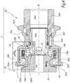
figure 4 est une coupe analogue auxfigures 1 à 3 lorsque le raccord est configuration accouplée, - la
figure 5 est une vue de détail correspondant au détail V à lafigure 1 , pour un raccord et un élément de raccord conformes à un deuxième mode de réalisation de l'invention, - la
figure 6 est une vue de détail correspondant au détail VI à lafigure 4 , pour le raccord et l'élément de raccord du deuxième mode de réalisation, - les
figures 7 et 8 sont des vues de détail respectivement analogues auxfigures 5 et 6 , pour un raccord et un élément de raccord conformes à un troisième mode de réalisation de l'invention, - les
figures 9 et 10 sont des vues de détails respectivement analogues auxfigures 5 et 6 , pour un raccord et un élément de raccord conformes à un quatrième mode de réalisation de l'invention, - la
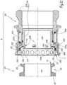
figure 11 est une coupe analogue à lafigure 1 pour un raccord et un élément de raccord conformes à un cinquième mode de réalisation de l'invention et - la
figure 12 est une coupe analogue à lafigure 4 pour le raccord et l'élément de raccord conformes au cinquième mode de l'invention.
- the
figure 1 is a longitudinal sectional view of the male and female elements of a fluidic connection according to the invention in uncoupled configuration, - the
figure 2 is a cut similar to thefigure 1 during a first step of fitting the coupling elements, - the
figure 3 is a cut similar to thefigure 2 during a second step of fitting, - the
figure 4 is a cut similar toFigures 1 to 3 when the fitting is coupled configuration, - the
figure 5 is a detail view corresponding to detail V at thefigure 1 for a coupling and a coupling element according to a second embodiment of the invention, - the
figure 6 is a detail view corresponding to detail VI to thefigure 4 for the connection and the connecting element of the second embodiment, - the
Figures 7 and 8 are respectively detailed views similar toFigures 5 and 6 for a coupling and a coupling element according to a third embodiment of the invention, - the
Figures 9 and 10 are views of details respectively similar toFigures 5 and 6 for a coupling and a coupling element according to a fourth embodiment of the invention, - the
figure 11 is a cut similar to thefigure 1 for a coupling and a coupling element according to a fifth embodiment of the invention and - the
figure 12 is a cut similar to thefigure 4 for the connector and the coupling element according to the fifth embodiment of the invention.
Le raccord fluidique R représenté aux
L'embout mâle 100 est de type embout clamp tel que défini par les normes DIN-32676 ou ASME BPE-2007 pour un embout de diamètre extérieur de bride égal à 25 mm. Pour un embout de diamètre extérieur de bride égal à 34, 50 ou 64 mm, celui-ci est défini par les normes ISO 2852, DIN 32676, BS 4825-3 et/ou ASME BPE-2007.The
Cet embout mâle 100 comprend un corps monobloc 102, de préférence réalisé en métal, qui définit un canal central 104 de circulation de fluide, lequel canal est raccordé, d'une façon connue en soi et sur l'arrière du corps 102, à une canalisation C1 de circulation de fluide. Pour la clarté du dessin, cette canalisation est représentée entre traits mixtes uniquement à la
A cet égard, on définit le côté avant d'un embout ou élément du raccord R comme le côté de cet embout ou élément orienté dans le sens de l'emmanchement ou de l'accouplement, c'est-à-dire orienté vers l'élément ou l'embout de raccord complémentaire pendant l'emmanchement. A l'inverse, on définit le côté arrière d'un embout ou élément du raccord R comme la direction opposée à l'élément ou l'embout de raccord complémentaire. Ainsi, dans l'exemple des
On note 1082 le bord avant de la bride 108, 1084 sa surface radiale externe et 1086 un chanfrein de jonction entre le bord 1082 et la surface 1084.1082 is the front edge of the
L'embout mâle 100 est pourvu d'une face avant 112 qui est ménagée en retrait vers l'arrière, par rapport au bord avant 1082 de la bride 108. Cette face avant est bordée, sur l'extérieur, par une rainure circonférentielle 114 qui est destinée à recevoir une partie d'un joint d'étanchéité lorsque cet embout 100 est utilisé de façon conventionnelle, en coopération avec un embout de forme analogue et avec un collier. La face avant 112 est disposée, radialement à l'axe X1, entre le canal central 104 et la rainure circonférentielle 114. En pratique, la face avant 112 et la rainure 114 sont réalisées sous la forme d'un lamage à partir de l'avant de l'embout mâle 100.The
L'élément femelle 200 est centré sur un axe longitudinal X2 et comprend un corps 202 destiné à recevoir une portion avant de l'embout mâle 100 en configuration accouplée du raccord R. Le corps 202 est formé d'une partie avant monobloc 2022 et d'une partie arrière monobloc 2024 vissée sur la partie avant, avec interposition d'un joint torique d'étanchéité 2026. Les parties 2022 et 2024 sont réalisées en métal, de préférence en acier.The
Le corps 202 définit un canal central 204 de passage de fluide. Ce canal central 204 est formé par deux canaux centraux unitaires 2042 et 2044 respectivement ménagés au centre d'une portion arrière de la partie avant 2022 et au centre de la partie arrière 2024 du corps 202. Ce canal 204 est raccordé, sur l'arrière du corps 202, à une canalisation C2 de circulation de fluide qui est représentée en traits mixtes uniquement à la
Un mécanisme de verrouillage 206 est prévu sur l'élément femelle 200 et comprend une rangée de billes 2062 disposée dans des orifices radiaux traversants 2064 ménagés dans le corps 202, à proximité de son bord avant 2021. Les orifices 2064 sont traversants en ce sens qu'ils débouchent à la fois sur une surface radiale interne 202s et sur une surface radiale externe 202t du corps 202. Le débouché de chaque orifice 2064 sur la surface radiale interne 202s du corps 202 présente un diamètre inférieur à celui des billes 2062, ce qui permet de limiter un mouvement centripète des billes 2062 en direction de l'axe X2. Le mécanisme 206 comprend également une bague de verrouillage 2066, qui est monté coulissante autour du corps 202, ainsi qu'un ressort 2068 qui exerce sur cette bague un effort élastique axial E2 dirigé vers l'avant de l'élément femelle 200. Le ressort 2068 est un ressort spiral de compression disposé radialement entre le corps 202 et la bague 2066, en appui contre un épaulement externe 202e du corps 202 et contre un épaulement interne 2066e de la bague de verrouillage 2066.A
Du côté de son bord avant 2021, le corps 202 présente un diamètre externe plus important que dans sa partie autour de laquelle est monté le ressort 2068. On note 2066s la surface radiale interne de la bague 2066 qui entoure la partie avant du corps 202 de plus grand diamètre. Cette surface 2066s présente un diamètre sensiblement égal au diamètre extérieur de la surface radiale externe 202t de la partie avant du corps 202, de telle sorte que, lorsque cette surface 2066s est en regard, le long de l'axe X2, avec les billes 2062, elle contraint ces billes à faire saillies radialement vers l'intérieur, par rapport à la surface radiale interne 202s du corps 202, à travers les débouchés respectifs des orifices 2064. Ceci correspond, notamment, à la configuration représentée à la
Au voisinage de son bord avant 2066b, la bague 2066 est pourvue d'une portion divergente 2066d dont la surface interne définit un chanfrein 2066c convergeant vers l'axe longitudinal X2 en s'éloignant du bord avant 2066b. Il est ainsi formé un volume creux V entre le chanfrein 2066c et la surface radiale externe 202t du corps 202 au niveau des orifices 2064.In the vicinity of its
D'autre part, la bague de verrouillage 2066 est pourvue d'une collerette périphérique externe 2066f sur laquelle un opérateur peut exercer un effort axial E4 parallèle à l'axe X2 et dirigé vers l'arrière, supérieur à l'effort E2, afin d'amener le volume V en regard des billes 2062 lorsque cela est nécessaire, comme expliqué ci-après.On the other hand, the
L'élément 200 définit par ailleurs une chambre d'étanchéité 208 dans laquelle est disposé un joint d'étanchéité 210 en élastomère.The
La chambre d'étanchéité entoure radialement le canal unitaire 2042 ménagé dans la partie avant 2022 du corps 202. Cette chambre d'étanchéité est délimitée, radialement à l'axe X2 entre une paroi radiale externe 2082 et une paroi radiale interne 2084 qui est pourvue de quatre ouvertures 2085 de mises en communication du canal 204 avec la chambre d'étanchéité 208. Le long de l'axe longitudinal X2, la chambre d'étanchéité 208 est délimitée entre une paroi avant 2086 et une paroi arrière 2088 qui relie les deux parties de diamètre différent du corps 202 mentionnées ci-dessus. Les parois 2082, 2084, 2086 et 2088 forment une pièce monobloc. Il s'agit de portions de la partie avant 2022 du corps 202. Ainsi la paroi 2084 est solidaire du corps 202, dans la mesure où elle est fixe par rapport à ce corps en configuration désaccouplée et en cours d'accouplement. La paroi radiale interne 2084 délimite la portion avant du canal 2042 et est radialement disposée entre l'axe longitudinal X2 et la chambre d'étanchéité 208.The sealing chamber radially surrounds the
Les parois 2082, 2084, 2086 et 2088 définissent respectivement des surfaces radiale interne 2082s, radiale externe 2084s, axiale arrière 2086s et axiale avant 2088s tournées vers la chambre d'étanchéité 208 et qui forment des contours de la chambre d'étanchéité 208.The
La chambre d'étanchéité 208 est disposée à l'arrière des logements 2064 et les logements 2064 sont ménagés dans la paroi avant 2086.The sealing
La chambre d'étanchéité 208 forme un volume annulaire autour de l'axe X2 au sein du corps 202.The sealing
Sous l'effort E2 du ressort 2068, en configuration désaccouplée, la bague de verrouillage 2066 vient en appui contre la surface extérieure 2088t de la paroi 2088 qui est opposée à la chambre d'étanchéité 208. La paroi radiale externe 2082 constitue le fond de la chambre d'étanchéité 208. La surface axiale arrière 2086s de la paroi avant 2086 s'étend radialement, à partir de la paroi radiale externe 2082 et vers l'axe longitudinal X2, sur une hauteur radiale inférieure à la dimension radiale de la surface avant 2088s de la paroi arrière 2088. En d'autres termes, la chambre d'étanchéité 208 est fermée du côté arrière de l'élément femelle 200, mais partiellement ouverte en direction du bord avant 2021. Plus précisément la chambre d'étanchéité 208 est ouverte selon l'axe longitudinal X2 en direction de l'embouchure de l'élément de raccord 200.Under the force E2 of the
On note 2084b le bord avant de la paroi radiale interne 2084 qui est dirigé vers l'avant de l'élément femelle 200. Ce bord avant est destiné à venir en appui contre la face avant 112 de l'embout mâle 100 en cours d'emmanchement des éléments 100 et 200 l'un dans l'autre et, éventuellement, en configuration accouplée du raccord R. Le bord avant 2084b est une surface perpendiculaire à l'axe X2. La surface radiale interne 2082s de la paroi radiale externe 2082 s'étend, entre la paroi arrière 2088 et la paroi avant 2086, sur une longueur axiale L2082 supérieure à la longueur axiale L2084 de la paroi radiale interne 2084. Plus précisément, la longueur axiale L2084 de la paroi radiale interne 2084, définie depuis la paroi arrière 2088 jusqu'au bord avant 2084b de la paroi radiale interne 2084, est comprise entre 50% et 90%, de préférence de l'ordre de 75%, de la longueur axiale L2082 de la surface radiale interne 2082s. En d'autres termes, la chambre d'étanchéité 208 est fermée du côté externe de l'élément femelle 200, mais partiellement ouverte radialement vers l'intérieur en direction de l'axe longitudinal X2.2084b is the front edge of the inner
Le bord avant 2084b de la paroi radiale interne 2084 est en retrait, le long de l'axe X2, par rapport à la surface axiale arrière 2086s. En d'autres termes, une distance axiale d1, mesurée parallèlement à l'axe X2, entre la surface axiale arrière 2086s et le bord avant 2084b, est non nulle et la surface axiale arrière 2086s est disposée plus en avant que le bord avant 2084b le long de l'axe X2.The
Le joint d'étanchéité 210 présente une géométrie de révolution autour d'un axe confondu avec l'axe X2 en configuration montée du joint 210 dans la chambre d'étanchéité 208. La section du joint 210 est, dans le plan des
Les dimensions du joint d'étanchéité 210 sont définies en fonction de celles de la chambre d'étanchéité 208, de telle sorte que, lorsqu'il est en place dans la chambre d'étanchéité 208, le joint d'étanchéité 210 vient en appui par sa base 2102 contre la paroi radiale externe 2082 qui constitue le fond de la chambre d'étanchéité 208. Dans la configuration désaccouplée représentée à la
On note d2 la distance radiale entre le bord radial interne de la paroi avant 2086, correspondant à la surface 202s, et la surface radiale externe 2084s de la paroi 2084. Cette distance d2 est supérieure à la hauteur radiale H210 du joint 210, ce qui permet d'introduire le joint d'étanchéité 210 dans la chambre d'étanchéité 208 par l'avant de l'élément femelle 200. L'ouverture radiale entre les parois 2084 et 2086, de hauteur radiale d2, permet également de retirer aisément le joint d'étanchéité 210, notamment pour une opération de nettoyage complète de l'élément femelle 200.D2 is the radial distance between the inner radial edge of the
Pour emmancher les éléments 100 et 200 l'un dans l'autre, les axes X1 et X2 sont alignés et définissent alors ensemble un axe central XR du raccord R. L'opérateur fait reculer la bague 2066 à l'encontre de l'effort élastique E2 exercé par le ressort 2068 en exerçant sur la collerette 2066f un effort E4 dirigé vers l'arrière de l'élément femelle 200. Cet effort E4 est maintenu jusqu'à ce que la bague de verrouillage 2066 vienne en appui par un épaulement 2066g contre un épaulement externe correspondant 202g ménagé sur le corps 202, plus précisément sur sa partie arrière 2024. On atteint alors la configuration de la
Dans ces conditions, il est possible d'introduire l'embout mâle 100 dans l'embouchure de l'élément femelle 200 définie par la surface radiale interne 202s. Lors de cette introduction, la bride 108 repousse radialement vers l'extérieur les billes 2062, au sein des orifices 2064, ce qui est possible car la surface 2066s ne s'oppose plus à ce déplacement radial centrifuge des billes 2062. Les billes 2062 atteignent ainsi une deuxième position différente de la première position représentée à la
Quand l'opérateur relâche son effort E4 sur la collerette 2066f, la bague de verrouillage 2066 est repoussée vers l'avant de l'élément femelle 200 par l'effort E2 du ressort 2068, ce qui a pour effet de réaligner axialement la surface 2066s avec les billes 2062. Le caractère convergent du chanfrein 2066c en direction de l'axe XR et vers l'arrière de l'élément femelle 200 facilite le déplacement centripète des billes 2062 car ce chanfrein fonctionne comme une rampe de renvoi des billes 2062 vers l'axe XR. Au terme du mouvement d'avance de la bague de verrouillage 2066 sous l'action du ressort 2068, par mise en butée contre la surface extérieure 2088t, la surface 2066s entoure radialement les billes de verrouillage 2062 et les maintient dans leur première position, où elles font saillie vers l'axe XR par rapport à la surface 202s. Les billes 2062 sont ainsi maintenues en prise dans la gorge 106, ce qui a pour effet de bloquer l'embout mâle 100 dans le corps 202 de l'élément femelle 200. Dans cette configuration représentée à la
En d'autres termes, les billes 2062 sont mobiles radialement par rapport à l'axe XR, au sein des orifices 2064 ménagés dans le corps 202, entre la première position de blocage représentée aux
La bague de verrouillage 2066 est, quant à elle, mobile le long de l'axe XR et autour du corps 202 entre une première position de maintien représentée aux
Lors du passage de l'embout mâle 100 de la position de la
Ainsi, le joint 210 est à la fois déplacé en translation vers l'arrière de l'élément femelle 200, s'il n'était pas déjà au contact de la surface 2088s de la paroi arrière 2088 avant l'accouplement, et fléchi, au niveau de la lame avant 2104.Thus, the
En fonction de la géométrie de l'embout, qui peut varier compte tenu des tolérances de fabrication du corps 102, le joint 210 est plus ou moins fléchi lors de l'introduction de l'embout 100 dans l'élément femelle 200. Dans tous les cas, un contact est assuré entre la bride 108 et la lame avant 2104 du joint 210, et entre le joint 210 et le corps 202, ce qui assure l'étanchéité.Depending on the geometry of the tip, which may vary due to manufacturing tolerances of the
Dans la configuration accouplée représentée à la
Dès lors que les billes 2062 s'engagent dans la gorge 106 et y sont maintenues par la bague de verrouillage 2066, c'est-à-dire dans la configuration de la
Dans la configuration accouplée, et en fonction de la géométrie exacte du corps 102, l'embout 100 peut pivoter autour d'un axe perpendiculaire au plan de la
Lorsqu'il convient de désaccoupler ou désemmancher l'embout 100 par rapport à l'élément femelle 200, après coupure du passage du fluide dans le raccord R, l'opérateur exerce à nouveau sur la bague 2066 l'effort axial E4, ce qui a pour effet de rétracter la bague 2066 vers l'arrière du corps 202. En maintenant la bague 2066 dans sa deuxième position rétractée vers l'arrière en butée contre l'épaulement externe 202g du corps 202, l'opérateur peut tirer sur l'embout mâle 100, dans le sens de la flèche F3, ce qui lui permet d'extraire l'embout 100 du corps 202. Cette extraction est rendue possible par le fait que la bague de verrouillage 2066 libère les billes 2062 qui peuvent s'écarter radialement de l'axe XR en pénétrant dans le volume V lorsqu'elles sont chassées de la gorge périphérique 106 par la bride 108. Ceci induit que les billes 2062 laissent libre le passage pour l'embout 100 à l'intérieur du corps 202.When it is necessary to uncouple or unmount the
Lorsque l'embout 100 a ainsi été extrait hors de l'élément femelle 200, l'opérateur relâche la bague de verrouillage 2066 qui est ramenée vers l'avant par le ressort 2068 en butée contre le corps 202. L'élément femelle 200 est alors à nouveau dans la configuration de la
Dans les deuxième à cinquième modes de réalisation représentés aux
Les
Dans le mode de réalisation des
Dans le troisième mode de réalisation représenté aux
Selon une variante non représentée de l'invention, le joint 210 de ce mode de réalisation est plein, c'est-à-dire dépourvu d'un évidement central, moyennant le choix d'un matériau suffisamment souple pour le joint 210 pour permettre sa déformation élastique sous l'effet de la bride 108.According to a variant not shown of the invention, the
Dans le quatrième mode de réalisation visible aux
Dans le cinquième mode de réalisation représenté aux
En variante, le bord 2124 prend appui uniquement contre la paroi arrière 2088. La rondelle élastique 212 repousse élastiquement le joint torique 210 en direction de la paroi avant 2086, en appui contre la surface axiale arrière 2086s et contre la surface radiale interne 2082s de la chambre d'étanchéité 208.Alternatively, the
Lors de l'introduction de l'embout mâle 100 dans le corps 202, la bride 108 parvient au contact du joint torique 210 qu'elle tend à repousser vers l'arrière de l'élément femelle 200. La rondelle 212 se déforme alors par rapport à sa configuration d'origine représentée à la
Selon un aspect qui n'est pas visible sur les
La rondelle 212 est de préférence réalisée en matériau polymère, par exemple PEEK.The
En configuration accouplée, l'inclinaison de l'embout 100 dans l'élément 200 par rapport à l'axe longitudinal X2 est limitée par la mise en butée de la face avant 112 et du bord avant 2084b et modifie, au moins localement, le fléchissement de la rondelle 212 qui maintient le joint 210 au contact du corps 102 mais modifie le volume dévolu au joint 210.In coupled configuration, the inclination of the
En variante non représentée, la rondelle 212 agit sur un joint de géométrie différente, non torique ou creux comme par exemple le joint 210 du troisième mode de réalisation décrit.In variant not shown, the
Quel que soit le mode de réalisation considéré, le fait que la chambre d'étanchéité 208 est délimitée radialement vers l'intérieur par la paroi 2084 permet de limiter les mouvements de pivotement de l'embout mâle 100 dans le corps 202 en configuration accouplée du raccord R, ce qui garantit le maintien de l'étanchéité assuré par le joint 210. Ceci tient compte du fait que, compte tenu de la géométrie d'un embout clamp dont la bride 108 a une longueur axiale faible, de l'ordre de 3 mm, on ne peut pas réduire le couple de pivotement de cet embout à l'intérieur du corps 202 par la seule mise en contact de la surface radiale externe de la bride 108 avec la surface radiale interne 202s du corps 202. En outre, les ouvertures traversantes 2085 permettent au fluide transitant à travers le raccord R de renforcer l'étanchéité en plaquant le joint 210 à la fois contre le corps 104 et contre les parois 2082 et/ou 2088 de la chambre d'étanchéité 208. Ces ouvertures 2085 permettent également au fluide circulant dans le raccord de venir nettoyer la chambre d'étanchéité 208, ce qui autorise d'espacer d'autant les opérations de maintenance du joint 210 et de nettoyage de la chambre d'étanchéité 208.Whatever the embodiment considered, the fact that the sealing
Le fait que la chambre 208 est réalisé dans une partie monobloc 2022 du corps 202, c'est-à-dire le fait que les parois 2082, 2084, 2086 et 2088 sont monoblocs, garantit précisément la géométrie de la chambre d'étanchéité 208, en fonction de la géométrie nominale de l'embout 100, ce qui limite l'amplitude de pivotement de l'embout mâle 100 dans le corps 102.The fact that the
De plus, comme le bord avant 2084b de la paroi radiale interne 2084 est en retrait de la surface axiale arrière 2086s de la paroi avant 2086, sur la distance d1, l'embout 100 peut, en cours d'accouplement, venir en contact étanche avec le joint 210 avant de parvenir en butée contre la paroi radiale interne 2084.In addition, since the
De plus, une partie du joint d'étanchéité 210, à savoir la lame avant 2104 dans les premier et deuxième modes de réalisation, la lame 2108 dans le troisième mode de réalisation et la portion radiale interne du joint 210 dans les troisième et cinquième mode de réalisation, dépasse de la paroi avant 2086, radialement, vers l'axe XR, au niveau d'une portion de l'axe longitudinal disposée à l'avant du bord avant 2084b. Quelle que soit la géométrie de l'embout, dans les limites de tolérance prévues, le contact étanche entre le joint 210 et le corps 102 de l'embout est optimisé lorsque le joint est apte à suivre le contour externe de l'embout en limitant la compression de la matière constituant le joint 210. Tel est en particulier le cas pour un joint qui se déforme en fléchissant comme dans les premier, deuxième et quatrième modes de réalisation ou qui occupe un volume variable comme dans le cinquième mode de réalisation.In addition, a portion of the
Quel que soit le mode de réalisation, le nettoyage de l'élément de raccord femelle 200 ne nécessite que le démontage du joint 210. On remarque également que, lorsque le joint 210 est symétrique par rapport à un plan radial à l'axe X2, les risques de mauvais montage sont limités.Whatever the embodiment, the cleaning of the
Un avantage particulier des premier, deuxième et quatrième modes de réalisation est qu'un joint 210 équipé d'une lame 2104, 2106 ou 2108 est relativement facile à retirer de la chambre d'étanchéité 208.A particular advantage of the first, second and fourth embodiments is that a
Quel que soit le mode de réalisation considéré, des organes de verrouillage autres que les billes 2062 peuvent être prévus notamment sous la forme de doigts rotatifs ou mobiles en rotation ou sous la forme de segments, dont le mouvement par rapport au corps 202 entre leur première position de blocage et leur deuxième position de libération a au moins une composante radiale, et qui interagissent avec la bague de verrouillage 2066.Whatever the embodiment considered, locking members other than the
Selon une autre variante, la paroi avant 2086 peut être omise avec la surface radiale interne 2082s au même niveau radial que la surface radiale interne 202s du corps 202 au niveau des orifices 2064.According to another variant, the
Selon une autre variante, le nombre d'ouverture 2085 n'est pas égal à quatre. Il peut en particulier être supérieur à quatre.According to another variant, the
Selon une autre variante, la bague est mobile en rotation autour du corps 202 entre sa première position de maintien des organes de verrouillage en position de blocage et sa deuxième position où elle libère les organes de verrouillage.According to another variant, the ring is rotatable about the
Le matériau du joint 210 peut être différent d'un élastomère, par exemple un silicone.The material of the
Les modes de réalisation et variantes envisagés ci-dessus peuvent être combinés pour générer de nouveaux modes de réalisation de l'invention.The embodiments and alternatives contemplated above may be combined to generate new embodiments of the invention.
Claims (15)
Applications Claiming Priority (1)
| Application Number | Priority Date | Filing Date | Title |
|---|---|---|---|
| FR1652114A FR3048754A1 (en) | 2016-03-14 | 2016-03-14 | FLUID CONNECTING ELEMENT AND FLUID CONNECTING COMPRISING SUCH A MEMBER |
Publications (2)
| Publication Number | Publication Date |
|---|---|
| EP3220034A1 true EP3220034A1 (en) | 2017-09-20 |
| EP3220034B1 EP3220034B1 (en) | 2018-09-12 |
Family
ID=56263847
Family Applications (1)
| Application Number | Title | Priority Date | Filing Date |
|---|---|---|---|
| EP17160476.2A Active EP3220034B1 (en) | 2016-03-14 | 2017-03-13 | Female element for a fluid coupling and fluid coupling including such an element |
Country Status (4)
| Country | Link |
|---|---|
| US (1) | US10738927B2 (en) |
| EP (1) | EP3220034B1 (en) |
| CN (1) | CN107191723B (en) |
| FR (1) | FR3048754A1 (en) |
Cited By (1)
| Publication number | Priority date | Publication date | Assignee | Title |
|---|---|---|---|---|
| FR3132555A1 (en) | 2022-02-10 | 2023-08-11 | Staubli Faverges | Female fluid connector element and fluid connector comprising such an element |
Families Citing this family (5)
| Publication number | Priority date | Publication date | Assignee | Title |
|---|---|---|---|---|
| FR3073919B1 (en) * | 2017-11-23 | 2019-12-20 | Staubli Faverges | MULTI-FITTING PLATE AND PLATE ASSEMBLY INCLUDING SUCH A MULTI-FITTING PLATE |
| SE542883C2 (en) * | 2018-09-21 | 2020-08-04 | Mann Teknik Ab | Pressure tight plug comprising a pressure relief channel |
| FR3096109B1 (en) * | 2019-05-14 | 2021-05-28 | Staubli Sa Ets | Female element and fluidic connection |
| FR3099224B1 (en) * | 2019-07-26 | 2021-08-06 | Staubli Sa Ets | Male fluidic connection element, fluidic connection comprising such a male element and method of assembling such a male element |
| FR3101389B1 (en) * | 2019-09-30 | 2021-10-22 | Staubli Sa Ets | Fluidic connection |
Citations (6)
| Publication number | Priority date | Publication date | Assignee | Title |
|---|---|---|---|---|
| GB749795A (en) * | 1953-11-20 | 1956-05-30 | Roleda Ltd | Mechanism for coupling cylindrical members together |
| US2854259A (en) * | 1955-05-16 | 1958-09-30 | Snap Tite Inc | Self-sealing detachable coupling |
| GB826599A (en) * | 1957-04-23 | 1960-01-13 | Erik Waldemar Broden | Detachable couplings for fluid conduits |
| US3106378A (en) | 1960-12-27 | 1963-10-08 | Stile Craft Mfg Inc | Quick connect, valved coupling |
| US3188123A (en) | 1961-05-05 | 1965-06-08 | Hansen Mfg Co | Tube coupling |
| GB1533080A (en) * | 1976-11-27 | 1978-11-22 | Walther Carl Kurt Gmbh | Pipe coupling |
Family Cites Families (14)
| Publication number | Priority date | Publication date | Assignee | Title |
|---|---|---|---|---|
| GB749794A (en) | 1953-11-19 | 1956-05-30 | Arthur Collier Junior | Improved tool for making tee or branch joints in tubing |
| US3378225A (en) * | 1965-10-14 | 1968-04-16 | Clifford H. Snyder Jr. | Valved fluid-tight coupling |
| DE2259429C2 (en) * | 1972-12-05 | 1982-06-03 | Kernforschungszentrum Karlsruhe Gmbh, 7500 Karlsruhe | Coupling for the detachable connection of a hose that is radioactively contaminated on the inside with a double hose inside to a closed containment |
| US4398561A (en) * | 1981-03-27 | 1983-08-16 | Imperial Clevite Inc. | Quick disconnect coupling with locked valving |
| FR2630524B1 (en) * | 1988-04-20 | 1990-08-03 | Parker Hannifin Rak Sa | VALVE COUPLER WITH MOBILE OUTER SOCKET |
| CN2267373Y (en) * | 1996-12-23 | 1997-11-12 | 白桂森 | Direct insertion type quick acting pipe joint |
| US6206432B1 (en) * | 1998-01-26 | 2001-03-27 | Nok Corporation | Ball-lock-type quick-acting connector |
| US6237631B1 (en) * | 1999-08-19 | 2001-05-29 | Parker-Hannifin Corporation | Low spill quick disconnect coupling |
| FR2890719B1 (en) | 2005-09-14 | 2007-10-12 | Staubli Faverges Sca | QUICK CONNECTION OF SECURITY FOR THE JOINING OF TWO PIPES |
| JP4378647B2 (en) * | 2006-09-20 | 2009-12-09 | Smc株式会社 | Pipe fitting |
| JP5319507B2 (en) | 2009-12-07 | 2013-10-16 | 東京瓦斯株式会社 | Joint member |
| US20130207381A1 (en) * | 2010-07-05 | 2013-08-15 | Australasian Steel Products Pty Ltd | Fluid coupling |
| WO2014050929A1 (en) * | 2012-09-28 | 2014-04-03 | 日東工器株式会社 | Female joint having safety function |
| FR3017689B1 (en) * | 2014-02-17 | 2016-03-11 | Staubli Sa Ets | BAIONNETTE CONNECTOR SUITABLE FOR REMOVABLE JUNCTION OF PIPELINES |
-
2016
- 2016-03-14 FR FR1652114A patent/FR3048754A1/en active Pending
-
2017
- 2017-03-02 US US15/447,362 patent/US10738927B2/en active Active
- 2017-03-13 EP EP17160476.2A patent/EP3220034B1/en active Active
- 2017-03-14 CN CN201710150768.0A patent/CN107191723B/en active Active
Patent Citations (6)
| Publication number | Priority date | Publication date | Assignee | Title |
|---|---|---|---|---|
| GB749795A (en) * | 1953-11-20 | 1956-05-30 | Roleda Ltd | Mechanism for coupling cylindrical members together |
| US2854259A (en) * | 1955-05-16 | 1958-09-30 | Snap Tite Inc | Self-sealing detachable coupling |
| GB826599A (en) * | 1957-04-23 | 1960-01-13 | Erik Waldemar Broden | Detachable couplings for fluid conduits |
| US3106378A (en) | 1960-12-27 | 1963-10-08 | Stile Craft Mfg Inc | Quick connect, valved coupling |
| US3188123A (en) | 1961-05-05 | 1965-06-08 | Hansen Mfg Co | Tube coupling |
| GB1533080A (en) * | 1976-11-27 | 1978-11-22 | Walther Carl Kurt Gmbh | Pipe coupling |
Cited By (2)
| Publication number | Priority date | Publication date | Assignee | Title |
|---|---|---|---|---|
| FR3132555A1 (en) | 2022-02-10 | 2023-08-11 | Staubli Faverges | Female fluid connector element and fluid connector comprising such an element |
| EP4227566A1 (en) | 2022-02-10 | 2023-08-16 | Staubli Faverges | Female fluid connector element and fluid connector comprising such an element |
Also Published As
| Publication number | Publication date |
|---|---|
| CN107191723A (en) | 2017-09-22 |
| US20170261139A1 (en) | 2017-09-14 |
| CN107191723B (en) | 2021-08-06 |
| EP3220034B1 (en) | 2018-09-12 |
| US10738927B2 (en) | 2020-08-11 |
| FR3048754A1 (en) | 2017-09-15 |
Similar Documents
| Publication | Publication Date | Title |
|---|---|---|
| EP3220034B1 (en) | Female element for a fluid coupling and fluid coupling including such an element | |
| EP2141402B1 (en) | Connection element with claws and connection including such an element | |
| EP2908042B1 (en) | Bayonet-type connector suitable for removable connection of pipes | |
| EP2878873B1 (en) | Cartridge-type quick-coupling device | |
| EP2439440B1 (en) | Coupling device with locking by threaded clamps and coupling including such a device | |
| EP1862720B1 (en) | Female connection element and quick connection including such an element | |
| EP3184870B1 (en) | Socket element for a quick connector and quick connector comprising such a socket element | |
| FR2930904A1 (en) | FAST COUPLING ASSEMBLY AND CLEARING TOOL | |
| FR2786848A1 (en) | BALL COUPLER | |
| EP2817548B1 (en) | Sealed-coupling device without a retention area | |
| FR2927143A1 (en) | FEMALE CONNECTING ELEMENT AND RAPID CONNECTING INCORPORATING SUCH A MEMBER | |
| FR3059756B1 (en) | DEVICE FOR CONNECTING A FLUID CONDUIT AND A MALE CONNECTION, AND ASSEMBLY COMPRISING SUCH DEVICE AND RELATED MALE CONNECTION | |
| FR3071301B1 (en) | CIRCUIT BREAKER AND PRESSURE FLUID HANDLING INSTALLATION COMPRISING SUCH A CIRCUIT BREAKER | |
| EP3196526B1 (en) | Quick coupling for the disconnectable connection of pipelines for fluids under pressure | |
| EP0989348B1 (en) | Quick-acting pipe coupling | |
| EP1164327A1 (en) | Connector with locking ramp | |
| EP3670992B1 (en) | Female connection element and fluid connector including a male connection element and said female connection element | |
| EP3599408B1 (en) | Quick coupling for removable connection of two pipes containing pressurised fluid | |
| EP2112416B1 (en) | Instant connection for at least one tube | |
| EP4124788A1 (en) | Male element for fluid connector and fluid connector comprising such a male element | |
| EP4004420B1 (en) | Male element for a fluidic coupling, fluidic coupling comprising such a male element, and method for assembling such a male element | |
| EP4040028A1 (en) | Connection element | |
| FR2578621A1 (en) | End connector for semi-stiff plastics pipe | |
| EP4166836A1 (en) | Quick connector and connection assembly comprising such a quick connector | |
| EP4336080A1 (en) | Female quick-connect fitting element |
Legal Events
| Date | Code | Title | Description |
|---|---|---|---|
| PUAI | Public reference made under article 153(3) epc to a published international application that has entered the european phase |
Free format text: ORIGINAL CODE: 0009012 |
|
| STAA | Information on the status of an ep patent application or granted ep patent |
Free format text: STATUS: THE APPLICATION HAS BEEN PUBLISHED |
|
| AK | Designated contracting states |
Kind code of ref document: A1 Designated state(s): AL AT BE BG CH CY CZ DE DK EE ES FI FR GB GR HR HU IE IS IT LI LT LU LV MC MK MT NL NO PL PT RO RS SE SI SK SM TR |
|
| AX | Request for extension of the european patent |
Extension state: BA ME |
|
| STAA | Information on the status of an ep patent application or granted ep patent |
Free format text: STATUS: REQUEST FOR EXAMINATION WAS MADE |
|
| 17P | Request for examination filed |
Effective date: 20180220 |
|
| RBV | Designated contracting states (corrected) |
Designated state(s): AL AT BE BG CH CY CZ DE DK EE ES FI FR GB GR HR HU IE IS IT LI LT LU LV MC MK MT NL NO PL PT RO RS SE SI SK SM TR |
|
| GRAP | Despatch of communication of intention to grant a patent |
Free format text: ORIGINAL CODE: EPIDOSNIGR1 |
|
| STAA | Information on the status of an ep patent application or granted ep patent |
Free format text: STATUS: GRANT OF PATENT IS INTENDED |
|
| INTG | Intention to grant announced |
Effective date: 20180404 |
|
| GRAS | Grant fee paid |
Free format text: ORIGINAL CODE: EPIDOSNIGR3 |
|
| GRAA | (expected) grant |
Free format text: ORIGINAL CODE: 0009210 |
|
| STAA | Information on the status of an ep patent application or granted ep patent |
Free format text: STATUS: THE PATENT HAS BEEN GRANTED |
|
| AK | Designated contracting states |
Kind code of ref document: B1 Designated state(s): AL AT BE BG CH CY CZ DE DK EE ES FI FR GB GR HR HU IE IS IT LI LT LU LV MC MK MT NL NO PL PT RO RS SE SI SK SM TR |
|
| REG | Reference to a national code |
Ref country code: GB Ref legal event code: FG4D Free format text: NOT ENGLISH |
|
| REG | Reference to a national code |
Ref country code: CH Ref legal event code: EP |
|
| REG | Reference to a national code |
Ref country code: IE Ref legal event code: FG4D Free format text: LANGUAGE OF EP DOCUMENT: FRENCH |
|
| REG | Reference to a national code |
Ref country code: DE Ref legal event code: R096 Ref document number: 602017000379 Country of ref document: DE |
|
| REG | Reference to a national code |
Ref country code: AT Ref legal event code: REF Ref document number: 1041009 Country of ref document: AT Kind code of ref document: T Effective date: 20181015 |
|
| REG | Reference to a national code |
Ref country code: NL Ref legal event code: MP Effective date: 20180912 |
|
| REG | Reference to a national code |
Ref country code: LT Ref legal event code: MG4D |
|
| PG25 | Lapsed in a contracting state [announced via postgrant information from national office to epo] |
Ref country code: SE Free format text: LAPSE BECAUSE OF FAILURE TO SUBMIT A TRANSLATION OF THE DESCRIPTION OR TO PAY THE FEE WITHIN THE PRESCRIBED TIME-LIMIT Effective date: 20180912 Ref country code: BG Free format text: LAPSE BECAUSE OF FAILURE TO SUBMIT A TRANSLATION OF THE DESCRIPTION OR TO PAY THE FEE WITHIN THE PRESCRIBED TIME-LIMIT Effective date: 20181212 Ref country code: GR Free format text: LAPSE BECAUSE OF FAILURE TO SUBMIT A TRANSLATION OF THE DESCRIPTION OR TO PAY THE FEE WITHIN THE PRESCRIBED TIME-LIMIT Effective date: 20181213 Ref country code: LT Free format text: LAPSE BECAUSE OF FAILURE TO SUBMIT A TRANSLATION OF THE DESCRIPTION OR TO PAY THE FEE WITHIN THE PRESCRIBED TIME-LIMIT Effective date: 20180912 Ref country code: NO Free format text: LAPSE BECAUSE OF FAILURE TO SUBMIT A TRANSLATION OF THE DESCRIPTION OR TO PAY THE FEE WITHIN THE PRESCRIBED TIME-LIMIT Effective date: 20181212 Ref country code: FI Free format text: LAPSE BECAUSE OF FAILURE TO SUBMIT A TRANSLATION OF THE DESCRIPTION OR TO PAY THE FEE WITHIN THE PRESCRIBED TIME-LIMIT Effective date: 20180912 Ref country code: RS Free format text: LAPSE BECAUSE OF FAILURE TO SUBMIT A TRANSLATION OF THE DESCRIPTION OR TO PAY THE FEE WITHIN THE PRESCRIBED TIME-LIMIT Effective date: 20180912 |
|
| PG25 | Lapsed in a contracting state [announced via postgrant information from national office to epo] |
Ref country code: LV Free format text: LAPSE BECAUSE OF FAILURE TO SUBMIT A TRANSLATION OF THE DESCRIPTION OR TO PAY THE FEE WITHIN THE PRESCRIBED TIME-LIMIT Effective date: 20180912 Ref country code: HR Free format text: LAPSE BECAUSE OF FAILURE TO SUBMIT A TRANSLATION OF THE DESCRIPTION OR TO PAY THE FEE WITHIN THE PRESCRIBED TIME-LIMIT Effective date: 20180912 Ref country code: AL Free format text: LAPSE BECAUSE OF FAILURE TO SUBMIT A TRANSLATION OF THE DESCRIPTION OR TO PAY THE FEE WITHIN THE PRESCRIBED TIME-LIMIT Effective date: 20180912 |
|
| REG | Reference to a national code |
Ref country code: AT Ref legal event code: MK05 Ref document number: 1041009 Country of ref document: AT Kind code of ref document: T Effective date: 20180912 |
|
| PG25 | Lapsed in a contracting state [announced via postgrant information from national office to epo] |
Ref country code: CZ Free format text: LAPSE BECAUSE OF FAILURE TO SUBMIT A TRANSLATION OF THE DESCRIPTION OR TO PAY THE FEE WITHIN THE PRESCRIBED TIME-LIMIT Effective date: 20180912 Ref country code: RO Free format text: LAPSE BECAUSE OF FAILURE TO SUBMIT A TRANSLATION OF THE DESCRIPTION OR TO PAY THE FEE WITHIN THE PRESCRIBED TIME-LIMIT Effective date: 20180912 Ref country code: ES Free format text: LAPSE BECAUSE OF FAILURE TO SUBMIT A TRANSLATION OF THE DESCRIPTION OR TO PAY THE FEE WITHIN THE PRESCRIBED TIME-LIMIT Effective date: 20180912 Ref country code: IS Free format text: LAPSE BECAUSE OF FAILURE TO SUBMIT A TRANSLATION OF THE DESCRIPTION OR TO PAY THE FEE WITHIN THE PRESCRIBED TIME-LIMIT Effective date: 20190112 Ref country code: EE Free format text: LAPSE BECAUSE OF FAILURE TO SUBMIT A TRANSLATION OF THE DESCRIPTION OR TO PAY THE FEE WITHIN THE PRESCRIBED TIME-LIMIT Effective date: 20180912 Ref country code: PL Free format text: LAPSE BECAUSE OF FAILURE TO SUBMIT A TRANSLATION OF THE DESCRIPTION OR TO PAY THE FEE WITHIN THE PRESCRIBED TIME-LIMIT Effective date: 20180912 Ref country code: NL Free format text: LAPSE BECAUSE OF FAILURE TO SUBMIT A TRANSLATION OF THE DESCRIPTION OR TO PAY THE FEE WITHIN THE PRESCRIBED TIME-LIMIT Effective date: 20180912 Ref country code: AT Free format text: LAPSE BECAUSE OF FAILURE TO SUBMIT A TRANSLATION OF THE DESCRIPTION OR TO PAY THE FEE WITHIN THE PRESCRIBED TIME-LIMIT Effective date: 20180912 Ref country code: IT Free format text: LAPSE BECAUSE OF FAILURE TO SUBMIT A TRANSLATION OF THE DESCRIPTION OR TO PAY THE FEE WITHIN THE PRESCRIBED TIME-LIMIT Effective date: 20180912 |
|
| PG25 | Lapsed in a contracting state [announced via postgrant information from national office to epo] |
Ref country code: SM Free format text: LAPSE BECAUSE OF FAILURE TO SUBMIT A TRANSLATION OF THE DESCRIPTION OR TO PAY THE FEE WITHIN THE PRESCRIBED TIME-LIMIT Effective date: 20180912 Ref country code: SK Free format text: LAPSE BECAUSE OF FAILURE TO SUBMIT A TRANSLATION OF THE DESCRIPTION OR TO PAY THE FEE WITHIN THE PRESCRIBED TIME-LIMIT Effective date: 20180912 Ref country code: PT Free format text: LAPSE BECAUSE OF FAILURE TO SUBMIT A TRANSLATION OF THE DESCRIPTION OR TO PAY THE FEE WITHIN THE PRESCRIBED TIME-LIMIT Effective date: 20190112 |
|
| REG | Reference to a national code |
Ref country code: DE Ref legal event code: R097 Ref document number: 602017000379 Country of ref document: DE |
|
| PLBE | No opposition filed within time limit |
Free format text: ORIGINAL CODE: 0009261 |
|
| STAA | Information on the status of an ep patent application or granted ep patent |
Free format text: STATUS: NO OPPOSITION FILED WITHIN TIME LIMIT |
|
| PG25 | Lapsed in a contracting state [announced via postgrant information from national office to epo] |
Ref country code: DK Free format text: LAPSE BECAUSE OF FAILURE TO SUBMIT A TRANSLATION OF THE DESCRIPTION OR TO PAY THE FEE WITHIN THE PRESCRIBED TIME-LIMIT Effective date: 20180912 |
|
| 26N | No opposition filed |
Effective date: 20190613 |
|
| PG25 | Lapsed in a contracting state [announced via postgrant information from national office to epo] |
Ref country code: SI Free format text: LAPSE BECAUSE OF FAILURE TO SUBMIT A TRANSLATION OF THE DESCRIPTION OR TO PAY THE FEE WITHIN THE PRESCRIBED TIME-LIMIT Effective date: 20180912 |
|
| PG25 | Lapsed in a contracting state [announced via postgrant information from national office to epo] |
Ref country code: MC Free format text: LAPSE BECAUSE OF FAILURE TO SUBMIT A TRANSLATION OF THE DESCRIPTION OR TO PAY THE FEE WITHIN THE PRESCRIBED TIME-LIMIT Effective date: 20180912 |
|
| PG25 | Lapsed in a contracting state [announced via postgrant information from national office to epo] |
Ref country code: LU Free format text: LAPSE BECAUSE OF NON-PAYMENT OF DUE FEES Effective date: 20190313 |
|
| PG25 | Lapsed in a contracting state [announced via postgrant information from national office to epo] |
Ref country code: IE Free format text: LAPSE BECAUSE OF NON-PAYMENT OF DUE FEES Effective date: 20190313 |
|
| PG25 | Lapsed in a contracting state [announced via postgrant information from national office to epo] |
Ref country code: MT Free format text: LAPSE BECAUSE OF FAILURE TO SUBMIT A TRANSLATION OF THE DESCRIPTION OR TO PAY THE FEE WITHIN THE PRESCRIBED TIME-LIMIT Effective date: 20180912 |
|
| PG25 | Lapsed in a contracting state [announced via postgrant information from national office to epo] |
Ref country code: CY Free format text: LAPSE BECAUSE OF FAILURE TO SUBMIT A TRANSLATION OF THE DESCRIPTION OR TO PAY THE FEE WITHIN THE PRESCRIBED TIME-LIMIT Effective date: 20180912 |
|
| PG25 | Lapsed in a contracting state [announced via postgrant information from national office to epo] |
Ref country code: HU Free format text: LAPSE BECAUSE OF FAILURE TO SUBMIT A TRANSLATION OF THE DESCRIPTION OR TO PAY THE FEE WITHIN THE PRESCRIBED TIME-LIMIT; INVALID AB INITIO Effective date: 20170313 |
|
| PG25 | Lapsed in a contracting state [announced via postgrant information from national office to epo] |
Ref country code: MK Free format text: LAPSE BECAUSE OF FAILURE TO SUBMIT A TRANSLATION OF THE DESCRIPTION OR TO PAY THE FEE WITHIN THE PRESCRIBED TIME-LIMIT Effective date: 20180912 |
|
| PGFP | Annual fee paid to national office [announced via postgrant information from national office to epo] |
Ref country code: FR Payment date: 20230327 Year of fee payment: 7 |
|
| PGFP | Annual fee paid to national office [announced via postgrant information from national office to epo] |
Ref country code: TR Payment date: 20230224 Year of fee payment: 7 Ref country code: GB Payment date: 20230327 Year of fee payment: 7 Ref country code: DE Payment date: 20230329 Year of fee payment: 7 Ref country code: BE Payment date: 20230327 Year of fee payment: 7 |
|
| P01 | Opt-out of the competence of the unified patent court (upc) registered |
Effective date: 20230509 |
|
| PGFP | Annual fee paid to national office [announced via postgrant information from national office to epo] |
Ref country code: CH Payment date: 20230402 Year of fee payment: 7 |