EP1164327A1 - Connector with locking ramp - Google Patents
Connector with locking ramp Download PDFInfo
- Publication number
- EP1164327A1 EP1164327A1 EP01420139A EP01420139A EP1164327A1 EP 1164327 A1 EP1164327 A1 EP 1164327A1 EP 01420139 A EP01420139 A EP 01420139A EP 01420139 A EP01420139 A EP 01420139A EP 1164327 A1 EP1164327 A1 EP 1164327A1
- Authority
- EP
- European Patent Office
- Prior art keywords
- ramp
- ring
- zone
- fitting
- fitting according
- Prior art date
- Legal status (The legal status is an assumption and is not a legal conclusion. Google has not performed a legal analysis and makes no representation as to the accuracy of the status listed.)
- Granted
Links
Images


Classifications
-
- F—MECHANICAL ENGINEERING; LIGHTING; HEATING; WEAPONS; BLASTING
- F16—ENGINEERING ELEMENTS AND UNITS; GENERAL MEASURES FOR PRODUCING AND MAINTAINING EFFECTIVE FUNCTIONING OF MACHINES OR INSTALLATIONS; THERMAL INSULATION IN GENERAL
- F16L—PIPES; JOINTS OR FITTINGS FOR PIPES; SUPPORTS FOR PIPES, CABLES OR PROTECTIVE TUBING; MEANS FOR THERMAL INSULATION IN GENERAL
- F16L37/00—Couplings of the quick-acting type
- F16L37/24—Couplings of the quick-acting type in which the connection is made by inserting one member axially into the other and rotating it to a limited extent, e.g. with bayonet action
- F16L37/244—Couplings of the quick-acting type in which the connection is made by inserting one member axially into the other and rotating it to a limited extent, e.g. with bayonet action the coupling being co-axial with the pipe
- F16L37/252—Couplings of the quick-acting type in which the connection is made by inserting one member axially into the other and rotating it to a limited extent, e.g. with bayonet action the coupling being co-axial with the pipe the male part having lugs on its periphery penetrating in the corresponding slots provided in the female part
-
- F—MECHANICAL ENGINEERING; LIGHTING; HEATING; WEAPONS; BLASTING
- F16—ENGINEERING ELEMENTS AND UNITS; GENERAL MEASURES FOR PRODUCING AND MAINTAINING EFFECTIVE FUNCTIONING OF MACHINES OR INSTALLATIONS; THERMAL INSULATION IN GENERAL
- F16L—PIPES; JOINTS OR FITTINGS FOR PIPES; SUPPORTS FOR PIPES, CABLES OR PROTECTIVE TUBING; MEANS FOR THERMAL INSULATION IN GENERAL
- F16L37/00—Couplings of the quick-acting type
- F16L37/28—Couplings of the quick-acting type with fluid cut-off means
- F16L37/30—Couplings of the quick-acting type with fluid cut-off means with fluid cut-off means in each of two pipe-end fittings
- F16L37/32—Couplings of the quick-acting type with fluid cut-off means with fluid cut-off means in each of two pipe-end fittings at least one of two lift valves being opened automatically when the coupling is applied
- F16L37/34—Couplings of the quick-acting type with fluid cut-off means with fluid cut-off means in each of two pipe-end fittings at least one of two lift valves being opened automatically when the coupling is applied at least one of the lift valves being of the sleeve type, i.e. a sleeve is telescoped over an inner cylindrical wall
Landscapes
- Engineering & Computer Science (AREA)
- General Engineering & Computer Science (AREA)
- Mechanical Engineering (AREA)
- Quick-Acting Or Multi-Walled Pipe Joints (AREA)
- Mechanical Operated Clutches (AREA)
Abstract
Description
L'invention a trait à un raccord qui comprend un premier et un second élément propres à s'emmancher l'un dans l'autre pour la jonction amovible de deux canalisations.The invention relates to a connector comprising a first and a second element suitable for fitting one inside the other for the removable connection of two pipes.
Il est connu d'utiliser des raccords avec double étanchéité pour des applications dans le domaine de la chimie, pour la connexion de circuits d'huile de refroidissement sur des presses ou pour le remplissage d'un réservoir de véhicule. Ces raccords peuvent avoir des diamètres nominaux importants en vue d'assurer des débits élevés.It is known to use fittings with double sealing for applications in the field of chemistry, for connection of cooling oil circuits to presses or for filling a vehicle tank. These fittings can have large nominal diameters to ensure high flow rates.
Avec les raccords de diamètres élevés, les efforts d'accouplement sont importants au point qu'il est parfois difficile de manoeuvrer à la main de tels raccords. En effet, les efforts d'accouplement doivent vaincre les efforts résistants exercés par un ou plusieurs ressorts sur un ou plusieurs clapets du raccord, ces ressorts ayant des constantes de raideurs d'autant plus importantes que le diamètre du raccord est important. Dans la première partie de la course d'accouplement, les efforts d'accouplement doivent également vaincre les efforts de friction de joints d'étanchéité.With large diameter fittings, the forces are important to the point that it is sometimes difficult to operate such fittings by hand. Indeed, mating efforts must overcome efforts resistance exerted by one or more springs on one or several valves of the fitting, these springs having constants stiffness all the more important as the diameter of the fitting is important. In the first part of the race the coupling forces must also overcome the friction forces of seals.
Il est connu, notamment par les raccords commercialisés
par la déposante sous la référence SPH/BA, d'équiper un
raccord dit rapide d'une ou plusieurs rampes de verrouillage.
Un tel raccord est représenté à la figure 7 et comprend un
élément mâle A pourvu de deux pions radiaux, dont un seul
apparaít sur la figure 7 avec la référence 101. L'élément
femelle B comprend une jupe 102 à l'intérieur de laquelle être
inséré l'élément mâle et dans laquelle sont ménagées deux
entailles, dont une seule est visible à la figure 7 avec la
référence 103. La géométrie de l'entaille 103 est telle qu'un
effort important doit être exercé pour le rapprochement des
éléments A et B lorsque le pion 101 est au voisinage de
l'ouverture d'entrée 103a de l'entaille 103. Il en résulte que
ce type de raccords ne peut pas être mis en oeuvre avec des
diamètres importants, les efforts à exercer ne permettant pas
une manoeuvre à la main.It is known, in particular by the fittings marketed
by the applicant under the reference SPH / BA, to equip a
so-called quick coupling of one or more locking ramps.
Such a connector is shown in Figure 7 and includes a
male element A provided with two radial pins, only one of which
appears in Figure 7 with the
Il est également connu d'utiliser des raccords vissés qui permettent de vaincre les efforts de rappel élastiques exercés par les ressorts et les efforts de friction dus aux joints. Cependant, l'opération d'accouplement est relativement lente dans la mesure où un nombre de tours important doit être utilisé pour obtenir une ouverture maximale du raccord.It is also known to use screw fittings which allow to overcome the elastic restoring efforts exerted by the springs and the friction forces due to the seals. However, the mating operation is relatively slow since a large number of turns must be used to obtain maximum opening of the fitting.
C'est à ces inconvénients qu'entend plus particulièrement remédier l'invention en proposant un nouveau raccord qui comprend une rampe de verrouillage et qui peut être manoeuvré à la main, même lorsqu'il est réalisé avec un diamètre nominal relativement important.It is to these disadvantages that we hear more particularly remedy the invention by proposing a new fitting which includes a locking ramp and which can be operated by hand, even when made with a nominal diameter relatively large.
Dans cet esprit, l'invention concerne un raccord pour la jonction amovible de canalisations qui comprend un premier et un second éléments propres à s'emmancher l'un dans l'autre selon un axe principal de ce raccord, le premier élément comprenant au moins une rampe formée dans une bague annulaire pour la réception d'une partie en saillie radiale du second élément en vue du verrouillage de ces éléments en configuration passante du raccord. La rampe comprend une ouverture d'entrée définie au niveau d'un bord libre de la bague. Ce raccord est caractérisé en ce que la rampe a, par rapport à un plan perpendiculaire à l'axe principal précité, un angle d'inclinaison plus faible dans une première zone, proche de l'ouverture d'entrée, que l'angle d'inclinaison correspondant dans une seconde zone, plus éloignée de cette ouverture que la première zone.In this spirit, the invention relates to a connector for the removable pipe junction which includes a first and a second element suitable for fitting one inside the other along a main axis of this connection, the first element comprising at least one ramp formed in an annular ring for the reception of a radial projecting part of the second element for locking these elements in configuration bandwidth of the fitting. The ramp includes an opening entry defined at a free edge of the ring. This fitting is characterized in that the ramp a, with respect to a plane perpendicular to the main axis mentioned above, an angle lower inclination in a first zone, close to the entrance opening, that the corresponding tilt angle in a second zone, further from this opening than the first zone.
Grâce à l'invention, la géométrie de la rampe permet de transformer le couple exercé par un opérateur pour assembler les éléments constitutifs du raccord en un effort adapté en permanence aux efforts résistants générés par des moyens de rappel élastique ou des joints du raccord. L'angle d'inclinaison relativement faible utilisé au voisinage de l'ouverture de la rampe permet d'exercer un effort relativement intense par la rotation relative des éléments précités, ce qui génère un effort de poussée important sur le ou les clapets du raccord en vue de leur décollement par rapport à leurs sièges respectifs. Ensuite, c'est-à-dire lorsque la partie en saillie du second élément est dans la seconde zone de la rampe, le déplacement des éléments constitutifs du raccord selon la direction de l'axe principal est plus rapide pour une rotation relative donnée de ces éléments, ce qui correspond au fait que les efforts résistants principaux ont déjà été vaincus. Ainsi, le couple de rotation que doit exercer un opérateur sur la bague de verrouillage est sensiblement constant au cours de l'accouplement des éléments du raccord, ce couple étant démultiplié de façon adaptée sur la longueur de la rampe de façon à générer un effort intense au début de l'accouplement et à permettre un déplacement axial relativement rapide de ces éléments lors d'une étape ultérieure de l'accouplement. Le temps de manoeuvre du raccord est réduit et optimisé, alors qu'il demeure adapté à une utilisation manuelle. En particulier, on peut utiliser des ressorts relativement puissants pour le rappel élastique des clapets en direction de leurs sièges respectifs, ce qui permet de mieux assurer l'appui des faces en contact des éléments mâles et femelles du raccord. On peut, en outre, utiliser des joints relativement serrés, en vue d'une étanchéité améliorée par rapport aux raccords connus.Thanks to the invention, the geometry of the ramp makes it possible to transform the torque exerted by an operator to assemble the constituent elements of the fitting in a suitable effort in permanence to the resistant efforts generated by means of elastic return or connection joints. The tilt angle relatively weak used near the opening of the ramp allows to exert a relatively intense effort by the relative rotation of the aforementioned elements, which generates a significant pushing force on the valve (s) of the fitting for detachment from their seats respective. Then, i.e. when the protruding part of the second element is in the second zone of the ramp, the displacement of the components of the fitting according to the direction of the main axis is faster for a rotation relative given of these elements, which corresponds to the fact that the main resistant efforts have already been defeated. So, the torque that an operator must exert on the locking ring is substantially constant during the coupling of the coupling elements, this torque being scaled appropriately along the length of the ramp so as to generate intense effort at the start of mating and allow relatively rapid axial displacement of these elements in a later stage of mating. The the operating time of the fitting is reduced and optimized, so that it remains suitable for manual use. In particular, relatively strong springs can be used for the elastic return of the valves in the direction of their respective seats, which provides better support for faces in contact with the male and female elements of the fitting. It is also possible to use relatively tight seals, for improved sealing compared to fittings known.
Selon un premier aspect avantageux de l'invention, la rampe comprend une troisième zone, plus éloignée de l'ouverture que la seconde zone et dont l'angle d'inclinaison par rapport au plan précité est plus faible que l'angle d'inclinaison correspondant de la seconde zone. Cette troisième zone constitue une zone de transition entre la seconde zone et une encoche de verrouillage de la partie en saillie du second élément. Cette troisième zone permet de limiter la vitesse axiale des éléments constitutifs du raccord lors de la phase terminale de leur verrouillage, phase dans laquelle les ressorts sont les plus comprimés et exercent les efforts résistants les plus intenses, et lors de la phase initiale de leur déverrouillage.According to a first advantageous aspect of the invention, the ramp includes a third zone, further from the opening than the second zone and whose angle of inclination by compared to the above-mentioned plane is smaller than the angle of inclination second zone correspondent. This third area constitutes a transition zone between the second zone and a locking notch of the projecting part of the second element. This third zone limits the speed axial of the components of the fitting during the phase end of their locking, phase in which the springs are the most compressed and exert the efforts most intense resistance, and during the initial phase of unlocking them.
Selon des modes de réalisation préférés de l'invention, les zones constitutives de la rampe peuvent être globalement rectilignes ou courbes, auquel cas leurs angles d'inclinaison respectifs sont définis comme leurs angles d'inclinaison moyen sur la longueur de chaque zone.According to preferred embodiments of the invention, the constituent zones of the ramp can be globally straight or curved, in which case their angles of inclination respective are defined as their mean tilt angles along the length of each zone.
On peut, en outre, prévoir que la partie en saillie du second élément comprend un galet monté fou sur un axe radial, le diamètre de ce galet étant inférieur à la largeur de la rampe. L'utilisation d'un galet permet d'améliorer le rendement du transfert de mouvement entre la rotation de la bague et le déplacement axial des éléments précités, grâce à une limitation des frottements générés.It can also be provided that the projecting part of the second element comprises a roller mounted idly on a radial axis, the diameter of this roller being less than the width of the ramp. The use of a roller improves the motion transfer efficiency between the rotation of the ring and the axial displacement of the aforementioned elements, thanks to a limitation of the friction generated.
Selon un premier mode de réalisation avantageux de l'invention, le premier élément est apte à pénétrer dans le second élément, le diamètre extérieur de la bague étant inférieur au diamètre intérieur d'un manchon du second élément équipé de la partie en saillie qui s'étend radialement en direction de l'axe principal du raccord. Dans ce cas, le premier élément constitue l'élément mâle du raccord alors que le second élément en constitue l'élément femelle.According to a first advantageous embodiment of the invention, the first element is able to penetrate the second element, the outside diameter of the ring being smaller than the inside diameter of a sleeve of the second element fitted with the projecting part which extends radially in direction of the main axis of the fitting. In this case, the first element constitutes the male element of the fitting whereas the second element constitutes the female element.
Selon un autre mode de réalisation avantageux de l'invention, le premier élément est apte à coiffer le second élément, le diamètre intérieur de la bague étant supérieur au diamètre extérieur d'un corps du second élément à partir duquel s'étend radialement, à l'opposé de l'axe principal du raccord, la partie en saillie. Dans ce cas, le premier élément constitue l'élément femelle du raccord, alors que le second élément en constitue l'élément mâle.According to another advantageous embodiment of the invention, the first element is suitable for styling the second element, the inner diameter of the ring being greater than outer diameter of a body of the second element from from which extends radially, opposite the main axis of the fitting, the projecting part. In this case, the first element constitutes the female element of the fitting, while the second element constitutes the male element.
Quel que soit le mode de réalisation considéré, on peut prévoir que la bague est pourvue de deux rampes sensiblement diamétralement opposées alors que le second élément est pourvu de deux parties en saillie également diamétralement opposées. Un raccord avec plus de deux rampes peut, bien sûr, être envisagé en restant dans le cadre de la présente invention.Whatever the embodiment considered, one can provide that the ring is provided with two substantially ramps diametrically opposite while the second element is provided of two also diametrically opposite projecting parts. A fitting with more than two ramps can, of course, be envisaged while remaining within the scope of the present invention.
Selon différents modes de réalisation, la rampe peut avoir une profondeur inférieure à l'épaisseur de la bague, auquel cas elle est formée par une rainure ménagée sur une surface radiale interne ou externe de la bague, ou être formée par une entaille ménagée dans cette bague.According to different embodiments, the ramp can have a depth less than the thickness of the ring, in which case it is formed by a groove made on a internal or external radial surface of the ring, or be formed by a cut in this ring.
L'invention sera mieux comprise et d'autres avantages de celle-ci apparaítront plus clairement à la lumière de la description qui va suivre de deux modes de réalisation d'un raccord conforme à son principe, donnée uniquement à titre d'exemple et faite en référence aux dessins annexés dans lesquels :
- la figure 1 est une vue de côté, avec arrachement partiel d'un raccord conforme à l'invention avant accouplement de ses éléments mâle et femelle ;
- la figure 2 est une coupe axiale du raccord de la figure 1 lors d'une première étape de l'accouplement de ses éléments mâle et femelle ;
- la figure 3 est une coupe analogue à la figure 2 en configuration verrouillée et passante du raccord ;
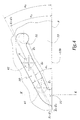
- la figure 4 est une vue développée d'une rampe du raccord des figures 1 à 3 ;
- la figure 5 est une vue extérieure en perspective d'un raccord conforme à un second mode de réalisation de l'invention et
- la figure 6 est une vue développée d'une rampe du raccord de la figure 5.
- Figure 1 is a side view, partially broken away of a connector according to the invention before coupling of its male and female elements;
- Figure 2 is an axial section of the connector of Figure 1 during a first step of the coupling of its male and female elements;
- Figure 3 is a section similar to Figure 2 in the locked configuration and passing the connector;
- Figure 4 is a developed view of a ramp of the connector of Figures 1 to 3;
- FIG. 5 is an external perspective view of a connector according to a second embodiment of the invention and
- FIG. 6 is a developed view of a ramp of the connector of FIG. 5.
Le raccord représenté sur les figures 1 à 4 comprend un élément mâle A et un élément femelle B prévus l'un et l'autre avec une forme globalement cylindrique à section circulaire. La partie arrière de l'élément mâle A est raccordée fluidiquement à une première canalisation C1, alors que la partie arrière de l'élément femelle B est raccordée à une seconde canalisation C2.The connector shown in Figures 1 to 4 comprises a male element A and a female element B each provided with a generally cylindrical shape with circular section. The rear part of the male element A is fluidly connected to a first line C 1 , while the rear part of the female element B is connected to a second line C 2 .
On note X-X' l'axe principal du raccord formé des éléments A et B, c'est-à-dire l'axe principal des éléments A et B dans les configurations des figures 1 à 3.We denote X-X 'the main axis of the fitting formed by elements A and B, i.e. the main axis of elements A and B in the configurations of FIGS. 1 to 3.
L'élément A comprend un corps 11 formé d'une base 12 et
d'une bague 13 de forme globalement cylindrique. Un poussoir
14 est prévu pour être monté fixe par rapport au corps 11 en
étant centré sur l'axe X-X'.Element A comprises a
Un clapet annulaire 15 est disposé autour du poussoir 14
et chargé élastiquement par un ressort 16 en direction d'un
siège 17 formé à l'intérieur de la bague 13. Deux joints 18
et 19 assurent respectivement l'étanchéité entre le clapet 15
et le poussoir 14 d'une part, et entre ce clapet et la bague
13 d'autre part.An
L'élément femelle B comprend un corps 21 formé d'une
partie centrale 22 et d'un manchon 23 monté autour de la
partie 22 et s'étendant au-delà de sa face avant 22a à
l'opposé de la canalisation C2. La partie 22 forme également
une butée centrale 22b disposée sur l'axe X-X' dans la
configuration des figures 1 à 3 et permettant l'appui d'un
ressort 26 exerçant, sur un clapet 25, un effort élastique
tentant à le plaquer sur un siège 27 formé dans la partie 22.
Un joint 28 monté sur le clapet 25 assure l'étanchéité entre
ce clapet et la partie 22.The female element B comprises a
La bague 13 est pourvue de deux rampes formées par des
rainures 30 et 30' ménagées dans la surface radiale externe
13a de la bague 13.The
La géométrie de la rainure 30 apparaít plus clairement
à la figure 4. Cette rainure s'étend à partir d'une ouverture
31 formée au niveau d'un bord libre 13b de la bague 13 opposé
à la canalisation C1 et définissant la face avant de l'élément
A. La rainure 30 comprend également une encoche 32 qui
constitue l'extrémité de la rainure 30 opposée à l'ouverture
31.The geometry of the
En partant de l'ouverture 31, la rainure 30 est divisée
en trois zones Z1, Z2, Z3 globalement rectilignes, la zone Z1
étant plus proche de l'ouverture 31 que la zone Z2 qui est
elle-même plus proche de cette ouverture que la zone Z3. On
note respectivement Z1-Z'1, Z2-Z'2 et Z3-Z'3, les axes géométriques
centraux des zones Z1, Z2 et Z3. On note α1 l'angle
entre l'axe Z1-Z'1 et un plan P perpendiculaire à l'axe X-X'
et passant par le bord libre 13b. De la même façon, on note
α2 l'angle entre l'axe Z2-Z'2 et le plan P et α3 l'angle entre
l'axe Z3-Z'3 et le plan P.Starting from the
L'angle α1 est inférieur à l'angle α2, alors que l'angle α3 est également inférieur à l'angle α2. Les angles α2 et α3 peuvent être égaux ou différents.The angle α 1 is less than the angle α 2 , while the angle α 3 is also less than the angle α 2 . The angles α 2 and α 3 can be equal or different.
L'élément femelle B est pourvu de deux tétons 40 et 40'
s'étendant chacun selon une direction radiale Y-Y' à partir
de la surface intérieure 23a du manchon 23 et en direction de
l'axe X-X'.The female element B is provided with two
Ces tétons 40 et 40' sont respectivement équipés d'un
galet 41, 41' monté fou sur le téton correspondant.These
Les tétons 40 et 40' sont représentés monoblocs avec le
manchon 23 sur les figures. Ils pourraient cependant être
rapportés sur ce manchon et immobilisés par tout moyen
adéquat.The
Lorsqu'il convient d'emmancher l'élément mâle A dans
l'élément femelle B, ceux-ci sont rapprochés l'un de l'autre,
comme représenté comme par les flèches F1 et F2 à la figure 1,
jusqu'à ce que le bord libre 13b de la bague 13 vienne en
appui contre les galets 41 et 41'. Il est alors possible de
faire subir à l'élément mâle A un mouvement de rotation
représenté par la flèche R1, ce qui a pour effet de déplacer
les ouvertures des rainures 30 et 30' jusqu'en regard des
galets 41 et 41'. En d'autres termes, on peut rechercher, "en
aveugle", la position d'engagement des galets 41 et 41' dans
les ouvertures, 31 et équivalente, des rainures 30 et 30'.When it is necessary to fit the male element A into the female element B, these are brought together, as shown by the arrows F 1 and F 2 in FIG. 1, until that the
Comme l'effort de rapprochement est maintenu, et comme
le diamètre d de ces galets est inférieur à la largeur l de
ces rainures, les galets pénètrent dans les ouvertures 31 et
équivalente. En poursuivant ce mouvement de rotation, chaque
galet 41 et 41' progresse en direction de l'encoche 32 ou 32'
de la rainure dans laquelle il est engagé.As the approximation force is maintained, and as the diameter d of these rollers is less than the width l of these grooves, the rollers penetrate into the
On est alors dans la position de la figure 2 où l'effort
de rapprochement représenté par les flèches F1 et F2 et généré
par la poursuite de la rotation R1 doit vaincre les efforts de
rappel élastique générés par les ressorts 16 et 26 et les
forces de frottement dues aux joints 18, 19 et 28. Cet effort
doit être intense.We are then in the position of FIG. 2 where the approximation force represented by the arrows F 1 and F 2 and generated by the continuation of the rotation R 1 must overcome the elastic restoring forces generated by the
Compte tenu du fait que l'angle α1 est relativement
faible, la rotation R1 de la bague 13 autour de l'axe X-X'
permet de générer, pour chaque rotation unitaire relative des
éléments A et B, un déplacement limité et un effort de
rapprochement intense, le galet 41 étant alors dans la zone
Z1, comme représenté en traits mixtes à la figure 4.Given the fact that the angle α 1 is relatively small, the rotation R 1 of the
Ensuite, lorsque les clapets 15 et 25 ont été respectivement
décollés de leurs sièges respectifs 17 et 27, et lorsque
les joints 18, 19 et 28 ne freinent plus leur déplacement,
l'intensité des efforts F1 et F2 générés par une rotation
unitaire R1 peut être diminuée, notamment du fait qu'une
circulation de fluide entre les canalisations C1 et C2
commence à s'établir. Dans ces conditions, le déplacement
axial unitaire obtenu pour chaque rotation unitaire de la
bague 13 peut être plus important, ce qui correspond au fait
que l'angle α2 est supérieur à l'angle α1, le galet 41
représenté en traits mixtes dans la zone Z2 progressant plus
rapidement parallèlement à l'axe X-X' lorsqu'il est dans cette
zone, que lorsqu'il est dans la zone Z1.Then, when the
Au terme de l'accouplement, c'est-à-dire dans la
configuration de la figure 3, les galets 41 et 41' sont reçus
dans les encoches terminales 32 et 32', ce qui évite un
mouvement en sens inverse de ces galets dans les rampes.At the end of mating, i.e. in the
configuration of Figure 3, the
Grâce à l'invention, le couple que doit exercer un
opérateur pour faire tourner la bague 13 dans le sens de la
flèche R1 est relativement constant alors que l'effort de
rapprochement généré F1, F2 est intense dans la configuration
de la figure 2 et qu'une progression axiale rapide des
éléments A et B l'un par rapport à l'autre est obtenue lorsque
les clapets sont décollés de leurs sièges respectifs.Thanks to the invention, the torque that an operator must exert to rotate the
La zone Z3 a un angle d'inclinaison α3 plus faible que l'angle α2 pour tenir compte de l'augmentation de l'effort résistant exercé par les ressorts qui sont fortement comprimés en fin de course.The zone Z3 has an angle of inclination α 3 smaller than the angle α 2 to take account of the increase in the resistant force exerted by the springs which are strongly compressed at the end of the race.
Comme il ressort des figures 2 et 3, la profondeur P des
rainures 30 et 30' est inférieure à l'épaisseur e de la bague
13, ce qui correspond au fait que ces rainures ne débouchent
pas dans le volume intérieur de l'élément A. Les rainures 30
et 30' n'affaiblissent pas sensiblement la bague 13 sur le
plan mécanique.As is apparent from FIGS. 2 and 3, the depth P of the
Dans le second mode de réalisation de l'invention
représenté à la figure 5, l'élément mâle A comprend un corps
71 équipé de tétons diamétralement opposés, dont un seul
apparaít à la figure 5 avec la référence 90. L'élément femelle
B comprend une bague 63 pourvue de deux entailles, dont une
seule apparaít à la figure 5 avec la référence 80. L'entaille
80 est formée dans toute l'épaisseur de la bague 63.In the second embodiment of the invention
shown in Figure 5, the male element A comprises a
L'entaille 80 comprend une ouverture d'entrée 81 et une
encoche 82 de blocage d'un téton 90 ou équivalent alors
qu'elle est divisée en deux zones Z1 et Z2 se faisant suite
entre l'ouverture 81 et l'encoche 82. Les zones Z1 et Z2 sont
courbes et l'on définit un axe moyen Z1-Z'1 correspondant à
l'orientation moyenne de la zone Z1 par rapport au bord libre
63b de la bague 63. De la même façon, on définit un axe Z2-Z'2
correspondant à l'inclinaison moyenne de la zone Z2.The
On note respectivement β1 et β2 les angles d'inclinaison
des axes Z1-Z'1 et Z2-Z'2 par rapport à un plan P passant par
le bord libre 63b et perpendiculaire à l'axe central X-X' du
raccord.We note respectively β 1 and β 2 the angles of inclination of the axes Z 1 -Z ' 1 and Z 2 -Z' 2 relative to a plane P passing through the
Conformément à l'invention, l'angle β1 est inférieur à l'angle β2.According to the invention, the angle β 1 is less than the angle β 2 .
Dans ce second mode de réalisation, les rampes pourraient
également être formées par des rainures qui seraient ménagées
sur la surface radiale interne de la bague 63 dans son
épaisseur.In this second embodiment, the ramps could
also be formed by grooves which would be formed
on the internal radial surface of the
Les diamètres respectifs des bagues et des corps des
raccords de l'invention sont adaptés à leur mode de coopération.
Plus précisément, le diamètre extérieur D13 de la bague
13 est plus petit que le diamètre intérieur d23 du manchon 23,
alors que le diamètre intérieur d63 de la bague 63 est plus
grand que le diamètre extérieur D71 du corps 71 qui porte les
tétons 90.The respective diameters of the rings and of the bodies of the fittings of the invention are adapted to their mode of cooperation. More specifically, the outside diameter D 13 of the
Les tétons 90 du second mode de réalisation pourraient
également être équipés de galets afin de limiter les frottements
dans les rampes, 80 et équivalente, de la bague 63.The
Selon une variante de l'invention, le second mode de réalisation pourrait comprendre une zone terminale équivalente à la zone Z3 du premier mode de réalisation. En fait, dans le cas de zones courbes, l'ensemble de ces zones Z1, Z2 et éventuellement Z3 forme une courbe convexe du côté d'appui du têton ou du galet.According to a variant of the invention, the second embodiment could include a terminal area equivalent to the area Z 3 of the first embodiment. In fact, in the case of curved zones, all of these zones Z 1 , Z 2 and possibly Z 3 form a convex curve on the bearing side of the pin or the roller.
Claims (10)
Applications Claiming Priority (2)
| Application Number | Priority Date | Filing Date | Title |
|---|---|---|---|
| FR0007648A FR2810388B1 (en) | 2000-06-15 | 2000-06-15 | LOCKING RAMP CONNECTION |
| FR0007648 | 2000-06-15 |
Publications (2)
| Publication Number | Publication Date |
|---|---|
| EP1164327A1 true EP1164327A1 (en) | 2001-12-19 |
| EP1164327B1 EP1164327B1 (en) | 2006-08-02 |
Family
ID=8851296
Family Applications (1)
| Application Number | Title | Priority Date | Filing Date |
|---|---|---|---|
| EP20010420139 Expired - Lifetime EP1164327B1 (en) | 2000-06-15 | 2001-06-14 | Connector with locking ramp |
Country Status (3)
| Country | Link |
|---|---|
| EP (1) | EP1164327B1 (en) |
| DE (1) | DE60121863T2 (en) |
| FR (1) | FR2810388B1 (en) |
Cited By (11)
| Publication number | Priority date | Publication date | Assignee | Title |
|---|---|---|---|---|
| US6877778B2 (en) | 2001-11-06 | 2005-04-12 | Staubli Faverges | Linearly actuated quick connect pipe couplings |
| FR2901595A1 (en) * | 2006-05-29 | 2007-11-30 | Staubli Faverges Sca | Connector`s male element for detachable junction of two pipelines, has protection groove whose notch locks pins with respect to locking ring in notch of locking ring, where notch of locking ring is oriented with respect to female element |
| JP4538080B1 (en) * | 2009-07-21 | 2010-09-08 | 株式会社猩々精機 | Fastening member |
| CN103016771A (en) * | 2012-12-14 | 2013-04-03 | 山西汾西重工有限责任公司 | Hand slide valve with axial locking function |
| JP2015028381A (en) * | 2013-06-28 | 2015-02-12 | シュトイブリー・ファベルゲ | Female quick connection element and quick connection including such a element |
| CN105378404A (en) * | 2013-04-18 | 2016-03-02 | 郑辉东 | Tube-fitting structure for pure-water line |
| US20160169432A1 (en) * | 2014-12-16 | 2016-06-16 | Les Industries Tournebo Inc. | Hydraulic cylinder joint and hydraulic cylinder pipe including same |
| CN105972361A (en) * | 2016-07-19 | 2016-09-28 | 无锡市五十五度科技有限公司 | High-pressure quick coupling for liquid |
| GB2547623A (en) * | 2015-11-20 | 2017-08-30 | Ivan Lucian | An apparatus for cleaning elevated windows and gutters |
| WO2017204239A1 (en) * | 2016-05-24 | 2017-11-30 | 日東工器株式会社 | Pipe joint comprising female joint member and male joint member |
| WO2023011406A1 (en) * | 2021-08-02 | 2023-02-09 | Rayconnect Fluid Handling System (zhenjiang) Co., Ltd. | Connector assembly |
Families Citing this family (2)
| Publication number | Priority date | Publication date | Assignee | Title |
|---|---|---|---|---|
| CN106090480B (en) * | 2016-08-22 | 2018-08-31 | 良工阀门集团浙江大业法兰有限公司 | Socket fitting structure |
| CN111633365A (en) * | 2020-06-24 | 2020-09-08 | 泰州天融科技有限公司 | Quick-release welding head for industrial welding robot |
Citations (3)
| Publication number | Priority date | Publication date | Assignee | Title |
|---|---|---|---|---|
| US2305841A (en) * | 1941-03-06 | 1942-12-22 | Weatherhead Co | Quick disconnect coupling with flow check |
| GB2155985A (en) * | 1984-02-16 | 1985-10-02 | Malcolm Gordon Victory | Bayonet fastening |
| US4909545A (en) * | 1982-12-15 | 1990-03-20 | Larry Hohol | Coupling |
-
2000
- 2000-06-15 FR FR0007648A patent/FR2810388B1/en not_active Expired - Fee Related
-
2001
- 2001-06-14 DE DE2001621863 patent/DE60121863T2/en not_active Expired - Lifetime
- 2001-06-14 EP EP20010420139 patent/EP1164327B1/en not_active Expired - Lifetime
Patent Citations (3)
| Publication number | Priority date | Publication date | Assignee | Title |
|---|---|---|---|---|
| US2305841A (en) * | 1941-03-06 | 1942-12-22 | Weatherhead Co | Quick disconnect coupling with flow check |
| US4909545A (en) * | 1982-12-15 | 1990-03-20 | Larry Hohol | Coupling |
| GB2155985A (en) * | 1984-02-16 | 1985-10-02 | Malcolm Gordon Victory | Bayonet fastening |
Cited By (19)
| Publication number | Priority date | Publication date | Assignee | Title |
|---|---|---|---|---|
| US6877778B2 (en) | 2001-11-06 | 2005-04-12 | Staubli Faverges | Linearly actuated quick connect pipe couplings |
| US6905151B2 (en) * | 2001-11-06 | 2005-06-14 | Staubli Faverges | Linearly actuated quick connect pipe couplings |
| FR2901595A1 (en) * | 2006-05-29 | 2007-11-30 | Staubli Faverges Sca | Connector`s male element for detachable junction of two pipelines, has protection groove whose notch locks pins with respect to locking ring in notch of locking ring, where notch of locking ring is oriented with respect to female element |
| EP1862719A1 (en) * | 2006-05-29 | 2007-12-05 | Staubli Faverges | Connection element with locking groove and joint including such an element |
| US7731243B2 (en) | 2006-05-29 | 2010-06-08 | Staubli Faverges | Coupling element for removably joining pipes |
| CN101082385B (en) * | 2006-05-29 | 2010-08-11 | 施托布利法韦日公司 | Connection element with locking groove and joint including such an element |
| JP4538080B1 (en) * | 2009-07-21 | 2010-09-08 | 株式会社猩々精機 | Fastening member |
| JP2011020733A (en) * | 2009-07-21 | 2011-02-03 | Shoujoh Seiki Corp | Fastening member |
| CN103016771A (en) * | 2012-12-14 | 2013-04-03 | 山西汾西重工有限责任公司 | Hand slide valve with axial locking function |
| CN105378404A (en) * | 2013-04-18 | 2016-03-02 | 郑辉东 | Tube-fitting structure for pure-water line |
| JP2015028381A (en) * | 2013-06-28 | 2015-02-12 | シュトイブリー・ファベルゲ | Female quick connection element and quick connection including such a element |
| US20160169432A1 (en) * | 2014-12-16 | 2016-06-16 | Les Industries Tournebo Inc. | Hydraulic cylinder joint and hydraulic cylinder pipe including same |
| GB2547623A (en) * | 2015-11-20 | 2017-08-30 | Ivan Lucian | An apparatus for cleaning elevated windows and gutters |
| GB2547623B (en) * | 2015-11-20 | 2018-02-28 | Ivan Lucian | An apparatus for cleaning elevated windows and/or gutters |
| WO2017204239A1 (en) * | 2016-05-24 | 2017-11-30 | 日東工器株式会社 | Pipe joint comprising female joint member and male joint member |
| JPWO2017204239A1 (en) * | 2016-05-24 | 2018-08-16 | 日東工器株式会社 | Pipe joint comprising a female joint member and a male joint member |
| US10663099B2 (en) | 2016-05-24 | 2020-05-26 | Nitto Kohki Co., Ltd | Pipe coupling comprising female coupling member and male coupling member |
| CN105972361A (en) * | 2016-07-19 | 2016-09-28 | 无锡市五十五度科技有限公司 | High-pressure quick coupling for liquid |
| WO2023011406A1 (en) * | 2021-08-02 | 2023-02-09 | Rayconnect Fluid Handling System (zhenjiang) Co., Ltd. | Connector assembly |
Also Published As
| Publication number | Publication date |
|---|---|
| FR2810388A1 (en) | 2001-12-21 |
| EP1164327B1 (en) | 2006-08-02 |
| DE60121863T2 (en) | 2007-03-15 |
| FR2810388B1 (en) | 2002-08-09 |
| DE60121863D1 (en) | 2006-09-14 |
Similar Documents
| Publication | Publication Date | Title |
|---|---|---|
| EP0406145B1 (en) | Seal assembly for locked sealed joints | |
| EP0231673B1 (en) | Composite sealing arrangement | |
| EP1531297B1 (en) | Female connection element and quick coupling comprising such an element | |
| EP1862720B1 (en) | Female connection element and quick connection including such an element | |
| FR2786848A1 (en) | BALL COUPLER | |
| FR3017689A1 (en) | BAIONNETTE CONNECTOR SUITABLE FOR REMOVABLE JUNCTION OF PIPELINES | |
| EP1164327B1 (en) | Connector with locking ramp | |
| EP1308663A2 (en) | Quick acting coupling for the disconnectable connection of two pipelines | |
| FR2901595A1 (en) | Connector`s male element for detachable junction of two pipelines, has protection groove whose notch locks pins with respect to locking ring in notch of locking ring, where notch of locking ring is oriented with respect to female element | |
| FR3007817A1 (en) | RAPID CONNECTION FEMALE ELEMENT AND RAPID CONNECTION COMPRISING SUCH A MEMBER | |
| FR2693250A1 (en) | Connection fitting for hydraulic lines. | |
| EP3220034B1 (en) | Female element for a fluid coupling and fluid coupling including such an element | |
| EP2778495B1 (en) | Female element and connector for performing the detachable connection of two fluid pipelines | |
| FR3023987A1 (en) | ||
| EP0526373B1 (en) | Locked pipe fitting with composite seal assembly | |
| EP3196526B1 (en) | Quick coupling for the disconnectable connection of pipelines for fluids under pressure | |
| EP0456538A1 (en) | Seal arrangement for a drive shaft with inner splines | |
| EP4124788A1 (en) | Male element for fluid connector and fluid connector comprising such a male element | |
| FR3107102A1 (en) | FLUIDIC CONNECTION | |
| FR3094772A1 (en) | Device for assembling two conduits, fluid circulation line and vehicle comprising such a device | |
| EP4306837A1 (en) | Connector element for a fluid connection to a terminal | |
| EP4336080A1 (en) | Female quick-connect fitting element | |
| EP0627058A1 (en) | Pipe fittings, particularly for flexible pipes | |
| FR2790057A1 (en) | Ball bearing coupler | |
| FR2535782A1 (en) | Torque transmission in screwed drill pipe coupling |
Legal Events
| Date | Code | Title | Description |
|---|---|---|---|
| PUAI | Public reference made under article 153(3) epc to a published international application that has entered the european phase |
Free format text: ORIGINAL CODE: 0009012 |
|
| AK | Designated contracting states |
Kind code of ref document: A1 Designated state(s): DE ES FR GB IT Kind code of ref document: A1 Designated state(s): AT BE CH CY DE DK ES FI FR GB GR IE IT LI LU MC NL PT SE TR |
|
| AX | Request for extension of the european patent |
Free format text: AL;LT;LV;MK;RO;SI |
|
| 17P | Request for examination filed |
Effective date: 20020131 |
|
| AKX | Designation fees paid |
Free format text: DE ES FR GB IT |
|
| GRAP | Despatch of communication of intention to grant a patent |
Free format text: ORIGINAL CODE: EPIDOSNIGR1 |
|
| GRAS | Grant fee paid |
Free format text: ORIGINAL CODE: EPIDOSNIGR3 |
|
| GRAA | (expected) grant |
Free format text: ORIGINAL CODE: 0009210 |
|
| AK | Designated contracting states |
Kind code of ref document: B1 Designated state(s): DE ES FR GB IT |
|
| PG25 | Lapsed in a contracting state [announced via postgrant information from national office to epo] |
Ref country code: IT Free format text: LAPSE BECAUSE OF FAILURE TO SUBMIT A TRANSLATION OF THE DESCRIPTION OR TO PAY THE FEE WITHIN THE PRESCRIBED TIME-LIMIT;WARNING: LAPSES OF ITALIAN PATENTS WITH EFFECTIVE DATE BEFORE 2007 MAY HAVE OCCURRED AT ANY TIME BEFORE 2007. THE CORRECT EFFECTIVE DATE MAY BE DIFFERENT FROM THE ONE RECORDED. Effective date: 20060802 |
|
| REG | Reference to a national code |
Ref country code: GB Ref legal event code: FG4D Free format text: NOT ENGLISH |
|
| GBT | Gb: translation of ep patent filed (gb section 77(6)(a)/1977) |
Effective date: 20060807 |
|
| REF | Corresponds to: |
Ref document number: 60121863 Country of ref document: DE Date of ref document: 20060914 Kind code of ref document: P |
|
| PG25 | Lapsed in a contracting state [announced via postgrant information from national office to epo] |
Ref country code: ES Free format text: LAPSE BECAUSE OF FAILURE TO SUBMIT A TRANSLATION OF THE DESCRIPTION OR TO PAY THE FEE WITHIN THE PRESCRIBED TIME-LIMIT Effective date: 20061113 |
|
| PLBE | No opposition filed within time limit |
Free format text: ORIGINAL CODE: 0009261 |
|
| STAA | Information on the status of an ep patent application or granted ep patent |
Free format text: STATUS: NO OPPOSITION FILED WITHIN TIME LIMIT |
|
| 26N | No opposition filed |
Effective date: 20070503 |
|
| REG | Reference to a national code |
Ref country code: FR Ref legal event code: PLFP Year of fee payment: 16 |
|
| REG | Reference to a national code |
Ref country code: FR Ref legal event code: PLFP Year of fee payment: 17 |
|
| REG | Reference to a national code |
Ref country code: FR Ref legal event code: PLFP Year of fee payment: 18 |
|
| PGFP | Annual fee paid to national office [announced via postgrant information from national office to epo] |
Ref country code: IT Payment date: 20190621 Year of fee payment: 19 |
|
| PGFP | Annual fee paid to national office [announced via postgrant information from national office to epo] |
Ref country code: FR Payment date: 20190625 Year of fee payment: 19 |
|
| PGFP | Annual fee paid to national office [announced via postgrant information from national office to epo] |
Ref country code: GB Payment date: 20190627 Year of fee payment: 19 Ref country code: DE Payment date: 20190627 Year of fee payment: 19 |
|
| REG | Reference to a national code |
Ref country code: DE Ref legal event code: R119 Ref document number: 60121863 Country of ref document: DE |
|
| GBPC | Gb: european patent ceased through non-payment of renewal fee |
Effective date: 20200614 |
|
| PG25 | Lapsed in a contracting state [announced via postgrant information from national office to epo] |
Ref country code: FR Free format text: LAPSE BECAUSE OF NON-PAYMENT OF DUE FEES Effective date: 20200630 Ref country code: GB Free format text: LAPSE BECAUSE OF NON-PAYMENT OF DUE FEES Effective date: 20200614 |
|
| PG25 | Lapsed in a contracting state [announced via postgrant information from national office to epo] |
Ref country code: DE Free format text: LAPSE BECAUSE OF NON-PAYMENT OF DUE FEES Effective date: 20210101 |
|
| PG25 | Lapsed in a contracting state [announced via postgrant information from national office to epo] |
Ref country code: IT Free format text: LAPSE BECAUSE OF NON-PAYMENT OF DUE FEES Effective date: 20200614 |