EP1164327A1 - Raccord à rampe de verrouillage - Google Patents
Raccord à rampe de verrouillage Download PDFInfo
- Publication number
- EP1164327A1 EP1164327A1 EP01420139A EP01420139A EP1164327A1 EP 1164327 A1 EP1164327 A1 EP 1164327A1 EP 01420139 A EP01420139 A EP 01420139A EP 01420139 A EP01420139 A EP 01420139A EP 1164327 A1 EP1164327 A1 EP 1164327A1
- Authority
- EP
- European Patent Office
- Prior art keywords
- ramp
- ring
- zone
- fitting
- fitting according
- Prior art date
- Legal status (The legal status is an assumption and is not a legal conclusion. Google has not performed a legal analysis and makes no representation as to the accuracy of the status listed.)
- Granted
Links
Images


Classifications
-
- F—MECHANICAL ENGINEERING; LIGHTING; HEATING; WEAPONS; BLASTING
- F16—ENGINEERING ELEMENTS AND UNITS; GENERAL MEASURES FOR PRODUCING AND MAINTAINING EFFECTIVE FUNCTIONING OF MACHINES OR INSTALLATIONS; THERMAL INSULATION IN GENERAL
- F16L—PIPES; JOINTS OR FITTINGS FOR PIPES; SUPPORTS FOR PIPES, CABLES OR PROTECTIVE TUBING; MEANS FOR THERMAL INSULATION IN GENERAL
- F16L37/00—Couplings of the quick-acting type
- F16L37/24—Couplings of the quick-acting type in which the connection is made by inserting one member axially into the other and rotating it to a limited extent, e.g. with bayonet action
- F16L37/244—Couplings of the quick-acting type in which the connection is made by inserting one member axially into the other and rotating it to a limited extent, e.g. with bayonet action the coupling being co-axial with the pipe
- F16L37/252—Couplings of the quick-acting type in which the connection is made by inserting one member axially into the other and rotating it to a limited extent, e.g. with bayonet action the coupling being co-axial with the pipe the male part having lugs on its periphery penetrating in the corresponding slots provided in the female part
-
- F—MECHANICAL ENGINEERING; LIGHTING; HEATING; WEAPONS; BLASTING
- F16—ENGINEERING ELEMENTS AND UNITS; GENERAL MEASURES FOR PRODUCING AND MAINTAINING EFFECTIVE FUNCTIONING OF MACHINES OR INSTALLATIONS; THERMAL INSULATION IN GENERAL
- F16L—PIPES; JOINTS OR FITTINGS FOR PIPES; SUPPORTS FOR PIPES, CABLES OR PROTECTIVE TUBING; MEANS FOR THERMAL INSULATION IN GENERAL
- F16L37/00—Couplings of the quick-acting type
- F16L37/28—Couplings of the quick-acting type with fluid cut-off means
- F16L37/30—Couplings of the quick-acting type with fluid cut-off means with fluid cut-off means in each of two pipe-end fittings
- F16L37/32—Couplings of the quick-acting type with fluid cut-off means with fluid cut-off means in each of two pipe-end fittings at least one of two lift valves being opened automatically when the coupling is applied
- F16L37/34—Couplings of the quick-acting type with fluid cut-off means with fluid cut-off means in each of two pipe-end fittings at least one of two lift valves being opened automatically when the coupling is applied at least one of the lift valves being of the sleeve type, i.e. a sleeve is telescoped over an inner cylindrical wall
Definitions
- the invention relates to a connector comprising a first and a second element suitable for fitting one inside the other for the removable connection of two pipes.
- fittings with double sealing for applications in the field of chemistry, for connection of cooling oil circuits to presses or for filling a vehicle tank.
- These fittings can have large nominal diameters to ensure high flow rates.
- Such a connector is shown in Figure 7 and includes a male element A provided with two radial pins, only one of which appears in Figure 7 with the reference 101.
- the element female B includes a skirt 102 inside which to be inserted the male element and in which are arranged two notches, only one of which is visible in Figure 7 with the reference 103.
- the geometry of the notch 103 is such that a significant effort must be exerted to bring the elements A and B when the pin 101 is in the vicinity of the entry opening 103a of the notch 103. It follows that this type of fittings cannot be used with large diameters, the efforts to be exerted do not allow one maneuver by hand.
- the invention relates to a connector for the removable pipe junction which includes a first and a second element suitable for fitting one inside the other along a main axis of this connection, the first element comprising at least one ramp formed in an annular ring for the reception of a radial projecting part of the second element for locking these elements in configuration bandwidth of the fitting.
- the ramp includes an opening entry defined at a free edge of the ring.
- This fitting is characterized in that the ramp a, with respect to a plane perpendicular to the main axis mentioned above, an angle lower inclination in a first zone, close to the entrance opening, that the corresponding tilt angle in a second zone, further from this opening than the first zone.
- the geometry of the ramp makes it possible to transform the torque exerted by an operator to assemble the constituent elements of the fitting in a suitable effort in permanence to the resistant efforts generated by means of elastic return or connection joints.
- the tilt angle relatively weak used near the opening of the ramp allows to exert a relatively intense effort by the relative rotation of the aforementioned elements, which generates a significant pushing force on the valve (s) of the fitting for detachment from their seats respective. Then, i.e. when the protruding part of the second element is in the second zone of the ramp, the displacement of the components of the fitting according to the direction of the main axis is faster for a rotation relative given of these elements, which corresponds to the fact that the main resistant efforts have already been defeated.
- the torque that an operator must exert on the locking ring is substantially constant during the coupling of the coupling elements, this torque being scaled appropriately along the length of the ramp so as to generate intense effort at the start of mating and allow relatively rapid axial displacement of these elements in a later stage of mating.
- the the operating time of the fitting is reduced and optimized, so that it remains suitable for manual use.
- relatively strong springs can be used for the elastic return of the valves in the direction of their respective seats, which provides better support for faces in contact with the male and female elements of the fitting. It is also possible to use relatively tight seals, for improved sealing compared to fittings known.
- the ramp includes a third zone, further from the opening than the second zone and whose angle of inclination by compared to the above-mentioned plane is smaller than the angle of inclination second zone correspondent.
- This third area constitutes a transition zone between the second zone and a locking notch of the projecting part of the second element.
- This third zone limits the speed axial of the components of the fitting during the phase end of their locking, phase in which the springs are the most compressed and exert the efforts most intense resistance, and during the initial phase of unlocking them.
- the constituent zones of the ramp can be globally straight or curved, in which case their angles of inclination respective are defined as their mean tilt angles along the length of each zone.
- the projecting part of the second element comprises a roller mounted idly on a radial axis, the diameter of this roller being less than the width of the ramp.
- the first element is able to penetrate the second element, the outside diameter of the ring being smaller than the inside diameter of a sleeve of the second element fitted with the projecting part which extends radially in direction of the main axis of the fitting.
- the first element constitutes the male element of the fitting whereas the second element constitutes the female element.
- the first element is suitable for styling the second element, the inner diameter of the ring being greater than outer diameter of a body of the second element from from which extends radially, opposite the main axis of the fitting, the projecting part.
- the first element constitutes the female element of the fitting, while the second element constitutes the male element.
- the ring is provided with two substantially ramps diametrically opposite while the second element is provided of two also diametrically opposite projecting parts.
- a fitting with more than two ramps can, of course, be envisaged while remaining within the scope of the present invention.
- the ramp can have a depth less than the thickness of the ring, in which case it is formed by a groove made on a internal or external radial surface of the ring, or be formed by a cut in this ring.
- the connector shown in Figures 1 to 4 comprises a male element A and a female element B each provided with a generally cylindrical shape with circular section.
- the rear part of the male element A is fluidly connected to a first line C 1
- the rear part of the female element B is connected to a second line C 2 .
- X-X the main axis of the fitting formed by elements A and B, i.e. the main axis of elements A and B in the configurations of FIGS. 1 to 3.
- Element A comprises a body 11 formed from a base 12 and a ring 13 of generally cylindrical shape.
- a pusher 14 is intended to be mounted fixed relative to the body 11 in being centered on the axis XX '.
- An annular valve 15 is arranged around the pusher 14 and loaded elastically by a spring 16 in the direction of a seat 17 formed inside the ring 13.
- Two seals 18 and 19 respectively provide the seal between the valve 15 and the pusher 14 on the one hand, and between this valve and the ring 13 on the other hand.
- the female element B comprises a body 21 formed by a central part 22 and a sleeve 23 mounted around the part 22 and extending beyond its front face 22 a opposite to the pipe C 2 .
- the part 22 also forms a central stop 22 b arranged on the axis XX 'in the configuration of FIGS. 1 to 3 and allowing the support of a spring 26 exerting, on a valve 25, an elastic force attempting to press it against a seat 27 formed in the part 22.
- a seal 28 mounted on the valve 25 seals between this valve and the part 22.
- the ring 13 is provided with two ramps formed by grooves 30 and 30 'formed in the outer radial surface 13a of the ring 13.
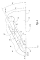
- the geometry of the groove 30 appears more clearly in Figure 4.
- This groove extends from an opening 31 formed at a free edge 13b of the ring 13 opposite the pipe C 1 and defining the face front of the element A.
- the groove 30 also comprises a notch 32 which constitutes the end of the groove 30 opposite the opening 31.
- the groove 30 is divided into three zones Z1, Z2, Z3 which are generally rectilinear, the zone Z1 being closer to the opening 31 than the zone Z2 which is itself closer to this opening than zone Z3.
- Z1-Z'1, Z2-Z'2 and Z3-Z'3 the central geometric axes of the zones Z1, Z2 and Z3.
- ⁇ 1 the angle between the axis Z1-Z'1 and a plane P perpendicular to the axis XX 'and passing through the free edge 13 b .
- ⁇ 2 the angle between the axis Z2-Z'2 and the plane P
- ⁇ 3 the angle between the axis Z3-Z'3 and the plane P.
- the angle ⁇ 1 is less than the angle ⁇ 2
- the angle ⁇ 3 is also less than the angle ⁇ 2 .
- the angles ⁇ 2 and ⁇ 3 can be equal or different.
- the female element B is provided with two pins 40 and 40 'each extending in a radial direction YY' from the inner surface 23 a of the sleeve 23 and in the direction of the axis XX '.
- pins 40 and 40 ' are respectively equipped with a roller 41, 41 'mounted idly on the corresponding stud.
- pins 40 and 40 ' are shown in one piece with the sleeve 23 in the figures. They could however be reported on this sleeve and immobilized by any means adequate.
- the intensity of the forces F 1 and F 2 generated by a unitary rotation R 1 can be reduced, in particular because a circulation of fluid between the pipes C 1 and C 2 begins to be established.
- the unitary axial displacement obtained for each unitary rotation of the ring 13 may be greater, which corresponds to the fact that the angle ⁇ 2 is greater than the angle ⁇ 1 , the roller 41 shown in phantom in the zone Z 2 progressing more quickly parallel to the axis XX 'when it is in this zone, than when it is in the zone Z 1 .
- rollers 41 and 41 ' are received in the terminal notches 32 and 32 ', which avoids a movement in the opposite direction of these rollers in the ramps.
- the torque that an operator must exert to rotate the ring 13 in the direction of the arrow R 1 is relatively constant while the approximation force generated F 1 , F 2 is intense in the configuration of the Figure 2 and that a rapid axial progression of the elements A and B relative to each other is obtained when the valves are detached from their respective seats.
- the zone Z3 has an angle of inclination ⁇ 3 smaller than the angle ⁇ 2 to take account of the increase in the resistant force exerted by the springs which are strongly compressed at the end of the race.
- the depth P of the grooves 30 and 30 ' is less than the thickness e of the ring 13, which corresponds to the fact that these grooves do not open into the interior volume of the element A
- the male element A comprises a body 71 fitted with diametrically opposed nipples, of which only one appears in Figure 5 with the reference 90.
- the female element B comprises a ring 63 provided with two notches, one of which only appears in Figure 5 with the reference 80.
- the notch 80 is formed throughout the thickness of the ring 63.
- the notch 80 comprises an inlet opening 81 and a notch 82 for blocking a stud 90 or equivalent while it is divided into two zones Z 1 and Z 2 following each other between the opening 81 and the notch 82.
- the zones Z 1 and Z 2 are curved and an average axis Z 1 -Z ′ 1 is defined corresponding to the average orientation of the zone Z 1 with respect to the free edge 63 b of the ring 63. From the same way, an axis Z 2 -Z ' 2 is defined corresponding to the average inclination of the zone Z 2 .
- ⁇ 1 and ⁇ 2 the angles of inclination of the axes Z 1 -Z ' 1 and Z 2 -Z' 2 relative to a plane P passing through the free edge 63b and perpendicular to the central axis XX 'of the connection.
- the angle ⁇ 1 is less than the angle ⁇ 2 .
- the ramps could also be formed by grooves which would be formed on the internal radial surface of the ring 63 in its thickness.
- the respective diameters of the rings and of the bodies of the fittings of the invention are adapted to their mode of cooperation. More specifically, the outside diameter D 13 of the ring 13 is smaller than the inside diameter d 23 of the sleeve 23, while the inside diameter d 63 of the ring 63 is larger than the outside diameter D 71 of the body 71 which carries nipples 90.
- the nipples 90 of the second embodiment could also be fitted with rollers to limit friction in the ramps, 80 and equivalent, of the ring 63.
- the second embodiment could include a terminal area equivalent to the area Z 3 of the first embodiment.
- all of these zones Z 1 , Z 2 and possibly Z 3 form a convex curve on the bearing side of the pin or the roller.
Abstract
Description
- la figure 1 est une vue de côté, avec arrachement partiel d'un raccord conforme à l'invention avant accouplement de ses éléments mâle et femelle ;
- la figure 2 est une coupe axiale du raccord de la figure 1 lors d'une première étape de l'accouplement de ses éléments mâle et femelle ;
- la figure 3 est une coupe analogue à la figure 2 en configuration verrouillée et passante du raccord ;
- la figure 4 est une vue développée d'une rampe du raccord des figures 1 à 3 ;
- la figure 5 est une vue extérieure en perspective d'un raccord conforme à un second mode de réalisation de l'invention et
- la figure 6 est une vue développée d'une rampe du raccord de la figure 5.
Claims (10)
- Raccord pour la jonction amovible de canalisations comprenant un premier et un second élément propres à s'emmancher l'un dans l'autre selon un axe principal dudit raccord, le premier élément comprenant au moins une rampe formée dans une bague pour la réception d'une partie en saillie radiale du second élément en vue du verrouillage desdits éléments en configuration passante dudit raccord, ladite rampe comprenant une ouverture d'entrée définie au niveau d'un bord libre de ladite bague, caractérisé en ce que ladite rampe (30, 30' ; 80) a, par rapport à un plan (P) perpendiculaire audit axe principal (X-X'), un angle d'inclinaison (α1 ; β1) plus faible dans une première zone (Z1) proche de ladite ouverture (31 ; 81) que l'angle d'inclinaison correspondant (α2 ; β2) dans une seconde zone (Z2), plus éloignée de ladite ouverture que ladite première zone.
- Raccord selon la revendication 1, caractérisé en ce que ladite rampe (30, 30') comprend une troisième zone (Z3), plus éloignée de ladite ouverture que ladite seconde zone (Z2) et dont l'angle d'inclinaison (α3) par rapport audit plan (P) est plus faible que l'angle d'inclinaison (α2) de ladite seconde zone.
- Raccord selon l'une des revendications précédentes, caractérisé en ce que lesdites zones (Z1-Z3) de ladite rampe sont globalement rectilignes.
- Raccord selon l'une des revendications 1 ou 2, caractérisé en ce que lesdites zones (Z1, Z2, Z3) de ladite rampe sont courbes, leurs angles d'inclinaison respectifs étant définis comme leurs angles d'inclinaison moyens (β1, β2) sur la longueur de chaque zone.
- Raccord selon l'une des revendications précédentes, caractérisé en ce que ladite partie en saillie comprend un galet (41, 41') monté fou sur un axe radial (40, 40'), le diamètre (d) dudit galet étant inférieur à la largeur (l) de ladite rampe (30, 30').
- Raccord selon l'une des revendications précédentes, caractérisé en ce que ledit premier élément (A) est apte à pénétrer dans ledit second élément (B), le diamètre extérieur (D13) de ladite bague (13) étant inférieur au diamètre intérieur (d23) d'un manchon (23) du second élément équipé de ladite partie en saillie (40, 40', 41, 41') qui s'étend radialement en direction dudit axe (X-X').
- Raccord selon l'une des revendications 1 à 5, caractérisé en ce que ledit premier élément (B) est apte à coiffer ledit second élément (A), le diamètre intérieur (d63) de ladite bague (63) étant supérieur au diamètre extérieur (D71) d'un corps (71) du second élément à partir duquel s'étend radialement, à l'opposé dudit axe (X-X'), ladite partie en saillie (90).
- Raccord selon l'une des revendications précédentes, caractérisé en ce que ladite bague (13 ; 63) est pourvue de deux rampes (30, 30' ; 80) sensiblement diamétralement opposées, alors que ledit second élément (B ; A) est pourvu de deux parties en saillies (40 , 40', 41, 41' ; 90) également diamétralement opposées.
- Raccord selon l'une des revendications précédentes, caractérisé en ce que ladite rampe a une profondeur (p) inférieure à l'épaisseur (e) de ladite bague (13), ladite rampe étant formée par une rainure (30, 30') ménagée sur une surface radiale (13a) de ladite bague.
- Raccord selon l'une des revendications 1 à 8, caractérisé en ce que ladite rampe est formée par une entaille (80) ménagée dans ladite bague (63).
Applications Claiming Priority (2)
| Application Number | Priority Date | Filing Date | Title |
|---|---|---|---|
| FR0007648A FR2810388B1 (fr) | 2000-06-15 | 2000-06-15 | Raccord a rampe de verrouillage |
| FR0007648 | 2000-06-15 |
Publications (2)
| Publication Number | Publication Date |
|---|---|
| EP1164327A1 true EP1164327A1 (fr) | 2001-12-19 |
| EP1164327B1 EP1164327B1 (fr) | 2006-08-02 |
Family
ID=8851296
Family Applications (1)
| Application Number | Title | Priority Date | Filing Date |
|---|---|---|---|
| EP20010420139 Expired - Lifetime EP1164327B1 (fr) | 2000-06-15 | 2001-06-14 | Raccord à rampe de verrouillage |
Country Status (3)
| Country | Link |
|---|---|
| EP (1) | EP1164327B1 (fr) |
| DE (1) | DE60121863T2 (fr) |
| FR (1) | FR2810388B1 (fr) |
Cited By (11)
| Publication number | Priority date | Publication date | Assignee | Title |
|---|---|---|---|---|
| US6877778B2 (en) | 2001-11-06 | 2005-04-12 | Staubli Faverges | Linearly actuated quick connect pipe couplings |
| FR2901595A1 (fr) * | 2006-05-29 | 2007-11-30 | Staubli Faverges Sca | Element de raccord a rainure de verrouillage et raccord incorporant un tel element |
| JP4538080B1 (ja) * | 2009-07-21 | 2010-09-08 | 株式会社猩々精機 | 締結部材 |
| CN103016771A (zh) * | 2012-12-14 | 2013-04-03 | 山西汾西重工有限责任公司 | 带轴向锁紧功能的手滑阀 |
| JP2015028381A (ja) * | 2013-06-28 | 2015-02-12 | シュトイブリー・ファベルゲ | メス側迅速継手要素及びこのような要素を備えた迅速継手 |
| CN105378404A (zh) * | 2013-04-18 | 2016-03-02 | 郑辉东 | 净水线的管接头结构 |
| US20160169432A1 (en) * | 2014-12-16 | 2016-06-16 | Les Industries Tournebo Inc. | Hydraulic cylinder joint and hydraulic cylinder pipe including same |
| CN105972361A (zh) * | 2016-07-19 | 2016-09-28 | 无锡市五十五度科技有限公司 | 一种液用高压快速接头 |
| GB2547623A (en) * | 2015-11-20 | 2017-08-30 | Ivan Lucian | An apparatus for cleaning elevated windows and gutters |
| WO2017204239A1 (fr) * | 2016-05-24 | 2017-11-30 | 日東工器株式会社 | Joint de tuyaux comprenant un élément de joint femelle et un élément de joint mâle |
| WO2023011406A1 (fr) * | 2021-08-02 | 2023-02-09 | Rayconnect Fluid Handling System (zhenjiang) Co., Ltd. | Ensemble raccord |
Families Citing this family (2)
| Publication number | Priority date | Publication date | Assignee | Title |
|---|---|---|---|---|
| CN106090480B (zh) * | 2016-08-22 | 2018-08-31 | 良工阀门集团浙江大业法兰有限公司 | 承插式管件结构 |
| CN111633365A (zh) * | 2020-06-24 | 2020-09-08 | 泰州天融科技有限公司 | 一种工业焊接机器人用快拆式焊接头 |
Citations (3)
| Publication number | Priority date | Publication date | Assignee | Title |
|---|---|---|---|---|
| US2305841A (en) * | 1941-03-06 | 1942-12-22 | Weatherhead Co | Quick disconnect coupling with flow check |
| GB2155985A (en) * | 1984-02-16 | 1985-10-02 | Malcolm Gordon Victory | Bayonet fastening |
| US4909545A (en) * | 1982-12-15 | 1990-03-20 | Larry Hohol | Coupling |
-
2000
- 2000-06-15 FR FR0007648A patent/FR2810388B1/fr not_active Expired - Fee Related
-
2001
- 2001-06-14 DE DE2001621863 patent/DE60121863T2/de not_active Expired - Lifetime
- 2001-06-14 EP EP20010420139 patent/EP1164327B1/fr not_active Expired - Lifetime
Patent Citations (3)
| Publication number | Priority date | Publication date | Assignee | Title |
|---|---|---|---|---|
| US2305841A (en) * | 1941-03-06 | 1942-12-22 | Weatherhead Co | Quick disconnect coupling with flow check |
| US4909545A (en) * | 1982-12-15 | 1990-03-20 | Larry Hohol | Coupling |
| GB2155985A (en) * | 1984-02-16 | 1985-10-02 | Malcolm Gordon Victory | Bayonet fastening |
Cited By (19)
| Publication number | Priority date | Publication date | Assignee | Title |
|---|---|---|---|---|
| US6877778B2 (en) | 2001-11-06 | 2005-04-12 | Staubli Faverges | Linearly actuated quick connect pipe couplings |
| US6905151B2 (en) * | 2001-11-06 | 2005-06-14 | Staubli Faverges | Linearly actuated quick connect pipe couplings |
| FR2901595A1 (fr) * | 2006-05-29 | 2007-11-30 | Staubli Faverges Sca | Element de raccord a rainure de verrouillage et raccord incorporant un tel element |
| EP1862719A1 (fr) * | 2006-05-29 | 2007-12-05 | Staubli Faverges | Elément de raccord à rainure de verrouillage et raccord incorporant un tel élément |
| US7731243B2 (en) | 2006-05-29 | 2010-06-08 | Staubli Faverges | Coupling element for removably joining pipes |
| CN101082385B (zh) * | 2006-05-29 | 2010-08-11 | 施托布利法韦日公司 | 具有锁定槽的联接元件及带有这种联接元件的联接结构 |
| JP4538080B1 (ja) * | 2009-07-21 | 2010-09-08 | 株式会社猩々精機 | 締結部材 |
| JP2011020733A (ja) * | 2009-07-21 | 2011-02-03 | Shoujoh Seiki Corp | 締結部材 |
| CN103016771A (zh) * | 2012-12-14 | 2013-04-03 | 山西汾西重工有限责任公司 | 带轴向锁紧功能的手滑阀 |
| CN105378404A (zh) * | 2013-04-18 | 2016-03-02 | 郑辉东 | 净水线的管接头结构 |
| JP2015028381A (ja) * | 2013-06-28 | 2015-02-12 | シュトイブリー・ファベルゲ | メス側迅速継手要素及びこのような要素を備えた迅速継手 |
| US20160169432A1 (en) * | 2014-12-16 | 2016-06-16 | Les Industries Tournebo Inc. | Hydraulic cylinder joint and hydraulic cylinder pipe including same |
| GB2547623A (en) * | 2015-11-20 | 2017-08-30 | Ivan Lucian | An apparatus for cleaning elevated windows and gutters |
| GB2547623B (en) * | 2015-11-20 | 2018-02-28 | Ivan Lucian | An apparatus for cleaning elevated windows and/or gutters |
| WO2017204239A1 (fr) * | 2016-05-24 | 2017-11-30 | 日東工器株式会社 | Joint de tuyaux comprenant un élément de joint femelle et un élément de joint mâle |
| JPWO2017204239A1 (ja) * | 2016-05-24 | 2018-08-16 | 日東工器株式会社 | 雌型継手部材と雄型継手部材とからなる管継手 |
| US10663099B2 (en) | 2016-05-24 | 2020-05-26 | Nitto Kohki Co., Ltd | Pipe coupling comprising female coupling member and male coupling member |
| CN105972361A (zh) * | 2016-07-19 | 2016-09-28 | 无锡市五十五度科技有限公司 | 一种液用高压快速接头 |
| WO2023011406A1 (fr) * | 2021-08-02 | 2023-02-09 | Rayconnect Fluid Handling System (zhenjiang) Co., Ltd. | Ensemble raccord |
Also Published As
| Publication number | Publication date |
|---|---|
| FR2810388A1 (fr) | 2001-12-21 |
| DE60121863D1 (de) | 2006-09-14 |
| EP1164327B1 (fr) | 2006-08-02 |
| FR2810388B1 (fr) | 2002-08-09 |
| DE60121863T2 (de) | 2007-03-15 |
Similar Documents
| Publication | Publication Date | Title |
|---|---|---|
| EP0406145B1 (fr) | Garniture d'étanchéité pour joints verrouillés étanches | |
| EP0231673B1 (fr) | Dispositif composite d'étanchéité | |
| EP1531297B1 (fr) | Elément femelle de raccord et raccord rapide incorporant un tel élément | |
| EP1862720B1 (fr) | Elément femelle de raccord et raccord rapide incorporant un tel élément | |
| FR2786848A1 (fr) | Coupleur a billes | |
| EP1164327B1 (fr) | Raccord à rampe de verrouillage | |
| EP1308663A2 (fr) | Raccord rapide pour la jonction amovible de deux canalisations | |
| FR2901595A1 (fr) | Element de raccord a rainure de verrouillage et raccord incorporant un tel element | |
| FR3007817A1 (fr) | Element femelle de raccord rapide et raccord rapide comprenant un tel element | |
| FR2693250A1 (fr) | Raccord de liaison pour conduites hydrauliques. | |
| EP3220034B1 (fr) | Elément de raccord fluidique et raccord fluidique comprenant un tel élément | |
| EP2778495B1 (fr) | Elément femelle et raccord destines à réaliser la jonction amovible de deux canalisations de fluide | |
| FR3023987A1 (fr) | ||
| EP0526373B1 (fr) | Assemblage verrouillé de tuyaux avec garniture d'étanchéité composite | |
| EP3196526B1 (fr) | Racord rapide pour la jonction amovible de canalisations de fluide sous pression | |
| EP0456538A1 (fr) | Dispositif d'obturation d'arbres d'entraînement à cannelures intérieures | |
| EP4124788A1 (fr) | Élément mâle de raccord fluidique et raccord fluidique comprenant un tel élément mâle | |
| EP3862610A1 (fr) | Raccord fluidique | |
| FR3094772A1 (fr) | Dispositif d’assemblage de deux conduits, ligne de circulation fluidique et véhicule comportant un tel dispositif | |
| EP4336080A1 (fr) | Élément femelle de raccord rapide | |
| EP0627058A1 (fr) | Raccord de tubes notamment de tubes souples | |
| FR2790057A1 (fr) | Coupleur a billes | |
| FR2535782A1 (fr) | Raccord de tubes de forage | |
| FR2775506A1 (fr) | Raccord a serrage rapide pour tubes, en particulier pour tubes en matiere plastique, et procede de fabrication d'un tel raccord | |
| FR2580368A1 (fr) | Perfectionnements aux raccords rapides pour la jonction amovible des canalisations |
Legal Events
| Date | Code | Title | Description |
|---|---|---|---|
| PUAI | Public reference made under article 153(3) epc to a published international application that has entered the european phase |
Free format text: ORIGINAL CODE: 0009012 |
|
| AK | Designated contracting states |
Kind code of ref document: A1 Designated state(s): DE ES FR GB IT Kind code of ref document: A1 Designated state(s): AT BE CH CY DE DK ES FI FR GB GR IE IT LI LU MC NL PT SE TR |
|
| AX | Request for extension of the european patent |
Free format text: AL;LT;LV;MK;RO;SI |
|
| 17P | Request for examination filed |
Effective date: 20020131 |
|
| AKX | Designation fees paid |
Free format text: DE ES FR GB IT |
|
| GRAP | Despatch of communication of intention to grant a patent |
Free format text: ORIGINAL CODE: EPIDOSNIGR1 |
|
| GRAS | Grant fee paid |
Free format text: ORIGINAL CODE: EPIDOSNIGR3 |
|
| GRAA | (expected) grant |
Free format text: ORIGINAL CODE: 0009210 |
|
| AK | Designated contracting states |
Kind code of ref document: B1 Designated state(s): DE ES FR GB IT |
|
| PG25 | Lapsed in a contracting state [announced via postgrant information from national office to epo] |
Ref country code: IT Free format text: LAPSE BECAUSE OF FAILURE TO SUBMIT A TRANSLATION OF THE DESCRIPTION OR TO PAY THE FEE WITHIN THE PRESCRIBED TIME-LIMIT;WARNING: LAPSES OF ITALIAN PATENTS WITH EFFECTIVE DATE BEFORE 2007 MAY HAVE OCCURRED AT ANY TIME BEFORE 2007. THE CORRECT EFFECTIVE DATE MAY BE DIFFERENT FROM THE ONE RECORDED. Effective date: 20060802 |
|
| REG | Reference to a national code |
Ref country code: GB Ref legal event code: FG4D Free format text: NOT ENGLISH |
|
| GBT | Gb: translation of ep patent filed (gb section 77(6)(a)/1977) |
Effective date: 20060807 |
|
| REF | Corresponds to: |
Ref document number: 60121863 Country of ref document: DE Date of ref document: 20060914 Kind code of ref document: P |
|
| PG25 | Lapsed in a contracting state [announced via postgrant information from national office to epo] |
Ref country code: ES Free format text: LAPSE BECAUSE OF FAILURE TO SUBMIT A TRANSLATION OF THE DESCRIPTION OR TO PAY THE FEE WITHIN THE PRESCRIBED TIME-LIMIT Effective date: 20061113 |
|
| PLBE | No opposition filed within time limit |
Free format text: ORIGINAL CODE: 0009261 |
|
| STAA | Information on the status of an ep patent application or granted ep patent |
Free format text: STATUS: NO OPPOSITION FILED WITHIN TIME LIMIT |
|
| 26N | No opposition filed |
Effective date: 20070503 |
|
| REG | Reference to a national code |
Ref country code: FR Ref legal event code: PLFP Year of fee payment: 16 |
|
| REG | Reference to a national code |
Ref country code: FR Ref legal event code: PLFP Year of fee payment: 17 |
|
| REG | Reference to a national code |
Ref country code: FR Ref legal event code: PLFP Year of fee payment: 18 |
|
| PGFP | Annual fee paid to national office [announced via postgrant information from national office to epo] |
Ref country code: IT Payment date: 20190621 Year of fee payment: 19 |
|
| PGFP | Annual fee paid to national office [announced via postgrant information from national office to epo] |
Ref country code: FR Payment date: 20190625 Year of fee payment: 19 |
|
| PGFP | Annual fee paid to national office [announced via postgrant information from national office to epo] |
Ref country code: GB Payment date: 20190627 Year of fee payment: 19 Ref country code: DE Payment date: 20190627 Year of fee payment: 19 |
|
| REG | Reference to a national code |
Ref country code: DE Ref legal event code: R119 Ref document number: 60121863 Country of ref document: DE |
|
| GBPC | Gb: european patent ceased through non-payment of renewal fee |
Effective date: 20200614 |
|
| PG25 | Lapsed in a contracting state [announced via postgrant information from national office to epo] |
Ref country code: FR Free format text: LAPSE BECAUSE OF NON-PAYMENT OF DUE FEES Effective date: 20200630 Ref country code: GB Free format text: LAPSE BECAUSE OF NON-PAYMENT OF DUE FEES Effective date: 20200614 |
|
| PG25 | Lapsed in a contracting state [announced via postgrant information from national office to epo] |
Ref country code: DE Free format text: LAPSE BECAUSE OF NON-PAYMENT OF DUE FEES Effective date: 20210101 |
|
| PG25 | Lapsed in a contracting state [announced via postgrant information from national office to epo] |
Ref country code: IT Free format text: LAPSE BECAUSE OF NON-PAYMENT OF DUE FEES Effective date: 20200614 |