EP3218168B2 - Verfahren und vorrichtung zur belichtungssteuerung einer selektiven lasersinter- oder laserschmelzvorrichtung - Google Patents
Verfahren und vorrichtung zur belichtungssteuerung einer selektiven lasersinter- oder laserschmelzvorrichtung Download PDFInfo
- Publication number
- EP3218168B2 EP3218168B2 EP15801125.4A EP15801125A EP3218168B2 EP 3218168 B2 EP3218168 B2 EP 3218168B2 EP 15801125 A EP15801125 A EP 15801125A EP 3218168 B2 EP3218168 B2 EP 3218168B2
- Authority
- EP
- European Patent Office
- Prior art keywords
- irradiation
- scanner
- exposure
- scanners
- individual
- Prior art date
- Legal status (The legal status is an assumption and is not a legal conclusion. Google has not performed a legal analysis and makes no representation as to the accuracy of the status listed.)
- Active
Links
Images
Classifications
-
- B—PERFORMING OPERATIONS; TRANSPORTING
- B33—ADDITIVE MANUFACTURING TECHNOLOGY
- B33Y—ADDITIVE MANUFACTURING, i.e. MANUFACTURING OF THREE-DIMENSIONAL [3D] OBJECTS BY ADDITIVE DEPOSITION, ADDITIVE AGGLOMERATION OR ADDITIVE LAYERING, e.g. BY 3D PRINTING, STEREOLITHOGRAPHY OR SELECTIVE LASER SINTERING
- B33Y10/00—Processes of additive manufacturing
-
- B—PERFORMING OPERATIONS; TRANSPORTING
- B29—WORKING OF PLASTICS; WORKING OF SUBSTANCES IN A PLASTIC STATE IN GENERAL
- B29C—SHAPING OR JOINING OF PLASTICS; SHAPING OF MATERIAL IN A PLASTIC STATE, NOT OTHERWISE PROVIDED FOR; AFTER-TREATMENT OF THE SHAPED PRODUCTS, e.g. REPAIRING
- B29C64/00—Additive manufacturing, i.e. manufacturing of three-dimensional [3D] objects by additive deposition, additive agglomeration or additive layering, e.g. by 3D printing, stereolithography or selective laser sintering
- B29C64/10—Processes of additive manufacturing
- B29C64/141—Processes of additive manufacturing using only solid materials
- B29C64/153—Processes of additive manufacturing using only solid materials using layers of powder being selectively joined, e.g. by selective laser sintering or melting
-
- B—PERFORMING OPERATIONS; TRANSPORTING
- B22—CASTING; POWDER METALLURGY
- B22F—WORKING METALLIC POWDER; MANUFACTURE OF ARTICLES FROM METALLIC POWDER; MAKING METALLIC POWDER; APPARATUS OR DEVICES SPECIALLY ADAPTED FOR METALLIC POWDER
- B22F10/00—Additive manufacturing of workpieces or articles from metallic powder
- B22F10/20—Direct sintering or melting
- B22F10/28—Powder bed fusion, e.g. selective laser melting [SLM] or electron beam melting [EBM]
-
- B—PERFORMING OPERATIONS; TRANSPORTING
- B22—CASTING; POWDER METALLURGY
- B22F—WORKING METALLIC POWDER; MANUFACTURE OF ARTICLES FROM METALLIC POWDER; MAKING METALLIC POWDER; APPARATUS OR DEVICES SPECIALLY ADAPTED FOR METALLIC POWDER
- B22F10/00—Additive manufacturing of workpieces or articles from metallic powder
- B22F10/30—Process control
- B22F10/36—Process control of energy beam parameters
- B22F10/366—Scanning parameters, e.g. hatch distance or scanning strategy
-
- B—PERFORMING OPERATIONS; TRANSPORTING
- B22—CASTING; POWDER METALLURGY
- B22F—WORKING METALLIC POWDER; MANUFACTURE OF ARTICLES FROM METALLIC POWDER; MAKING METALLIC POWDER; APPARATUS OR DEVICES SPECIALLY ADAPTED FOR METALLIC POWDER
- B22F12/00—Apparatus or devices specially adapted for additive manufacturing; Auxiliary means for additive manufacturing; Combinations of additive manufacturing apparatus or devices with other processing apparatus or devices
- B22F12/40—Radiation means
- B22F12/49—Scanners
-
- B—PERFORMING OPERATIONS; TRANSPORTING
- B23—MACHINE TOOLS; METAL-WORKING NOT OTHERWISE PROVIDED FOR
- B23K—SOLDERING OR UNSOLDERING; WELDING; CLADDING OR PLATING BY SOLDERING OR WELDING; CUTTING BY APPLYING HEAT LOCALLY, e.g. FLAME CUTTING; WORKING BY LASER BEAM
- B23K26/00—Working by laser beam, e.g. welding, cutting or boring
- B23K26/02—Positioning or observing the workpiece, e.g. with respect to the point of impact; Aligning, aiming or focusing the laser beam
- B23K26/06—Shaping the laser beam, e.g. by masks or multi-focusing
- B23K26/0604—Shaping the laser beam, e.g. by masks or multi-focusing by a combination of beams
-
- B—PERFORMING OPERATIONS; TRANSPORTING
- B29—WORKING OF PLASTICS; WORKING OF SUBSTANCES IN A PLASTIC STATE IN GENERAL
- B29C—SHAPING OR JOINING OF PLASTICS; SHAPING OF MATERIAL IN A PLASTIC STATE, NOT OTHERWISE PROVIDED FOR; AFTER-TREATMENT OF THE SHAPED PRODUCTS, e.g. REPAIRING
- B29C64/00—Additive manufacturing, i.e. manufacturing of three-dimensional [3D] objects by additive deposition, additive agglomeration or additive layering, e.g. by 3D printing, stereolithography or selective laser sintering
- B29C64/20—Apparatus for additive manufacturing; Details thereof or accessories therefor
- B29C64/264—Arrangements for irradiation
- B29C64/277—Arrangements for irradiation using multiple radiation means, e.g. micromirrors or multiple light-emitting diodes [LED]
-
- B—PERFORMING OPERATIONS; TRANSPORTING
- B29—WORKING OF PLASTICS; WORKING OF SUBSTANCES IN A PLASTIC STATE IN GENERAL
- B29C—SHAPING OR JOINING OF PLASTICS; SHAPING OF MATERIAL IN A PLASTIC STATE, NOT OTHERWISE PROVIDED FOR; AFTER-TREATMENT OF THE SHAPED PRODUCTS, e.g. REPAIRING
- B29C64/00—Additive manufacturing, i.e. manufacturing of three-dimensional [3D] objects by additive deposition, additive agglomeration or additive layering, e.g. by 3D printing, stereolithography or selective laser sintering
- B29C64/30—Auxiliary operations or equipment
- B29C64/386—Data acquisition or data processing for additive manufacturing
- B29C64/393—Data acquisition or data processing for additive manufacturing for controlling or regulating additive manufacturing processes
-
- B—PERFORMING OPERATIONS; TRANSPORTING
- B33—ADDITIVE MANUFACTURING TECHNOLOGY
- B33Y—ADDITIVE MANUFACTURING, i.e. MANUFACTURING OF THREE-DIMENSIONAL [3D] OBJECTS BY ADDITIVE DEPOSITION, ADDITIVE AGGLOMERATION OR ADDITIVE LAYERING, e.g. BY 3D PRINTING, STEREOLITHOGRAPHY OR SELECTIVE LASER SINTERING
- B33Y30/00—Apparatus for additive manufacturing; Details thereof or accessories therefor
-
- B—PERFORMING OPERATIONS; TRANSPORTING
- B33—ADDITIVE MANUFACTURING TECHNOLOGY
- B33Y—ADDITIVE MANUFACTURING, i.e. MANUFACTURING OF THREE-DIMENSIONAL [3D] OBJECTS BY ADDITIVE DEPOSITION, ADDITIVE AGGLOMERATION OR ADDITIVE LAYERING, e.g. BY 3D PRINTING, STEREOLITHOGRAPHY OR SELECTIVE LASER SINTERING
- B33Y50/00—Data acquisition or data processing for additive manufacturing
- B33Y50/02—Data acquisition or data processing for additive manufacturing for controlling or regulating additive manufacturing processes
-
- G—PHYSICS
- G02—OPTICS
- G02B—OPTICAL ELEMENTS, SYSTEMS OR APPARATUS
- G02B26/00—Optical devices or arrangements for the control of light using movable or deformable optical elements
- G02B26/08—Optical devices or arrangements for the control of light using movable or deformable optical elements for controlling the direction of light
- G02B26/10—Scanning systems
-
- H—ELECTRICITY
- H01—ELECTRIC ELEMENTS
- H01S—DEVICES USING THE PROCESS OF LIGHT AMPLIFICATION BY STIMULATED EMISSION OF RADIATION [LASER] TO AMPLIFY OR GENERATE LIGHT; DEVICES USING STIMULATED EMISSION OF ELECTROMAGNETIC RADIATION IN WAVE RANGES OTHER THAN OPTICAL
- H01S3/00—Lasers, i.e. devices using stimulated emission of electromagnetic radiation in the infrared, visible or ultraviolet wave range
- H01S3/10—Controlling the intensity, frequency, phase, polarisation or direction of the emitted radiation, e.g. switching, gating, modulating or demodulating
- H01S3/101—Lasers provided with means to change the location from which, or the direction in which, laser radiation is emitted
-
- H—ELECTRICITY
- H01—ELECTRIC ELEMENTS
- H01S—DEVICES USING THE PROCESS OF LIGHT AMPLIFICATION BY STIMULATED EMISSION OF RADIATION [LASER] TO AMPLIFY OR GENERATE LIGHT; DEVICES USING STIMULATED EMISSION OF ELECTROMAGNETIC RADIATION IN WAVE RANGES OTHER THAN OPTICAL
- H01S3/00—Lasers, i.e. devices using stimulated emission of electromagnetic radiation in the infrared, visible or ultraviolet wave range
- H01S3/10—Controlling the intensity, frequency, phase, polarisation or direction of the emitted radiation, e.g. switching, gating, modulating or demodulating
- H01S3/102—Controlling the intensity, frequency, phase, polarisation or direction of the emitted radiation, e.g. switching, gating, modulating or demodulating by controlling the active medium, e.g. by controlling the processes or apparatus for excitation
-
- B—PERFORMING OPERATIONS; TRANSPORTING
- B22—CASTING; POWDER METALLURGY
- B22F—WORKING METALLIC POWDER; MANUFACTURE OF ARTICLES FROM METALLIC POWDER; MAKING METALLIC POWDER; APPARATUS OR DEVICES SPECIALLY ADAPTED FOR METALLIC POWDER
- B22F12/00—Apparatus or devices specially adapted for additive manufacturing; Auxiliary means for additive manufacturing; Combinations of additive manufacturing apparatus or devices with other processing apparatus or devices
- B22F12/90—Means for process control, e.g. cameras or sensors
-
- Y—GENERAL TAGGING OF NEW TECHNOLOGICAL DEVELOPMENTS; GENERAL TAGGING OF CROSS-SECTIONAL TECHNOLOGIES SPANNING OVER SEVERAL SECTIONS OF THE IPC; TECHNICAL SUBJECTS COVERED BY FORMER USPC CROSS-REFERENCE ART COLLECTIONS [XRACs] AND DIGESTS
- Y02—TECHNOLOGIES OR APPLICATIONS FOR MITIGATION OR ADAPTATION AGAINST CLIMATE CHANGE
- Y02P—CLIMATE CHANGE MITIGATION TECHNOLOGIES IN THE PRODUCTION OR PROCESSING OF GOODS
- Y02P10/00—Technologies related to metal processing
- Y02P10/25—Process efficiency
Definitions
- the invention relates to a method for controlling the exposure of a selective laser sintering or laser melting device for producing three-dimensional objects with the method steps of the preamble of claim 1.
- the irradiation times of each individual scanner and/or the irradiation areas detected by this individual scanner are first recorded and stored separately in a first step.
- the detection of the irradiation times can be determined, for example, by a shutter opening signal that allows radiation energy from a radiation source to pass through, but other detection options are also conceivable, for example using light-sensitive elements or the like, which provide a time signal that is electronic when a scanner is activated can be saved.
- the irradiation areas can also be recorded in different ways, either phototechnically by recording an irradiation image in a certain period of time or by relying on determined irradiation times and scanner deflections, so that irradiated construction area sections can be determined with regard to their irradiated size.
- the recorded and stored irradiation time values and irradiation area values are electronically compared with one another. This can be done using a comparison device that is integrated in a correspondingly suitable processor or computer.
- a new division of the surface areas of a powder layer to be irradiated by each individual scanner is determined in such a way that the irradiation times for each individual scanner are as close as possible are brought closer together and/or the irradiation surface of each individual scanner is as close to one another as possible in terms of area.
- This process is carried out iteratively, i.e. repeated again and again, so that the irradiation geometries that change during the construction process can be responded to quickly.
- the division of the scan fields is dynamically adjusted after one or more layers have solidified in such a way that the resulting exposure time for each scanner is at least approximately the same for each subsequent irradiation pass.
- an operator can preset the scan fields for each scanner based on readable control data from the scanners. Of course, it is also possible for an operator to intervene manually in the iterative adjustment of the scan characters during the construction process and to deliberately shift the scan fields, for example for thermal reasons or the like.
- the process according to the invention can also be carried out as a “mixed process”, i.e. H. that e.g. B. irradiation times and irradiation areas can be measured and e.g. B. from the irradiation times of a first scanner, areas irradiated by it are inferred, which are compared with the irradiation areas of a second scanner in order to achieve the approximation.
- a “mixed process” i.e. H. that e.g. B. irradiation times and irradiation areas can be measured and e.g. B. from the irradiation times of a first scanner, areas irradiated by it are inferred, which are compared with the irradiation areas of a second scanner in order to achieve the approximation.
- the boundary between the scan fields of two scanners can be a straight line. However, if more than two scanners are in use over a construction area, it can be advantageous to choose other borders between the scan areas.
- the control according to the invention adjusts the boundary between the scan fields of different scanners in an optimal manner. Because the change in enamel surface and position over one Although large throughout the entire construction process, they are usually relatively small from layer to layer, the control is able to bring the construction time close to the theoretical minimum through small incremental adjustments to the scan field boundary throughout the entire construction process.
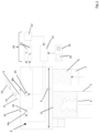
- the device 1 shown includes, as essential components, a process chamber 2, in which a construction container 3 with a height-adjustable construction platform 4 is arranged.
- a coater arrangement 5 is arranged above the construction platform 4, through which building material 6 can be applied from a metering chamber 7 in the area of the construction container 3 in the form of thin layers.
- a plurality of scanners 8a, 8b are arranged in the process chamber 2 above the construction container 3, through which the radiation 9 from a radiation source 10 in the form of a laser can be directed onto the building material layer 11 in a process-controlled manner in order to selectively solidify it.
- the device also has an electronic detection unit 20, via which irradiation times based on each scanner 8 and/or irradiation areas detected by a scanner 8 during an irradiation step can be recorded separately and stored in an electronic memory 21.
- An electronic comparison device 22 is connected to the memory 21, through which the stored irradiation time values of the individual scanners 8 can be compared with one another.
- a processor device 23 is connected to the comparison device 22, which, in the event of deviating irradiation time values of the individual scanners 8, redefines the surface areas to be exposed by each individual scanner 8 in such a way that the irradiation times (or the irradiation areas) of each individual scanner 8 are as large as possible in terms of area are aligned with each other.
- FIG. 1 an input device 25 with a display 26 is also shown, via which an operator can intervene in the construction process of the laser sintering or laser melting device 1.
- the radiation 9 from the radiation source 10 is guided via a beam splitter 15, and from there passes through a window 16 in the upper region of the process chamber 2 in order to reach the scanners 8a, 8b.
- the detection unit 20 includes sensor elements on the scanners or optical switches (shutters) connected upstream of them, which record the irradiation times of the scanners 8 and store them in the memory 21 as irradiation time values T1 and T2 to be compared. These values are compared with one another in the comparison device 22 in order to enable the processor to optimize the control of the scanners.
- the irradiation time recording can be replaced or supplemented by irradiation area recording, that the memory and the comparator can be part of an electronic system for operating the device and can be integrated into a computer or processor.
- the boundary 30 between the scan fields 31, 32 oscillates in order to avoid streaking in the component.
Landscapes
- Engineering & Computer Science (AREA)
- Chemical & Material Sciences (AREA)
- Materials Engineering (AREA)
- Manufacturing & Machinery (AREA)
- Physics & Mathematics (AREA)
- Optics & Photonics (AREA)
- Mechanical Engineering (AREA)
- Health & Medical Sciences (AREA)
- Toxicology (AREA)
- Plasma & Fusion (AREA)
- Electromagnetism (AREA)
- General Health & Medical Sciences (AREA)
- Automation & Control Theory (AREA)
- Microelectronics & Electronic Packaging (AREA)
- General Physics & Mathematics (AREA)
- Powder Metallurgy (AREA)
Description
- Die Erfindung betrifft ein Verfahren zur Belichtungssteuerung einer selektiven Lasersinter- oder Laserschmelzvorrichtung zum Herstellen von dreidimensionalen Objekten mit den Verfahrensschritten des Oberbegriffes des Anspruches 1.
- Als Stand der Technik ist es aus
DE 10 2014 005 916.2 bereits bekannt, Lasersinter- oder Laserschmelzvorrichtungen, mit welchen dreidimensionale Objekte durch selektives Bestrahlen eines Baumaterials hergestellt werden können, mit einer Mehrzahl von Scannern durchzuführen. Die Scanner sind über einem Baufeld angeordnet und können entweder fest oder beweglich, d.h. über dem Baufeldbereich bereichsweise verfahrbar angeordnet werden. - Bei derartigen Mehr-Scanneranlagen ist entweder jedem Abschnitt eines Baufeldes ein gesonderter Scanner zugeordnet oder die Scanner sind derart angebracht oder ausgebildet, dass sie auch zumindest teilweise Baufeldabschnitte belichten können, die eigentlich einen anderen Scanner zugeordnet sind, um diesen anderen Scanner bei der Belichtung des ihm zugeordneten Baufeldbereiches zu unterstützen, wenn dort der Belichtungsaufwand zeitmäßig oder flächenmäßig deutlich höher ist als in dem benachbarten Baufeldabschnitt, der dann entsprechend weniger zu belichten ist. Das Dokument JP 2009 006509 A offenbart ein Verfahren gemäß dem Oberbegriff des Anspruchs 1. Der vorliegenden Erfindung liegt die Aufgabe zugrunde, ein Verfahren anzugeben, das eine Optimierung des Bauvorganges und insbesondere eine Verkürzung der erforderlichen Bauzeit für einen Gegenstand ermöglicht. Diese Aufgabe wird durch die Kombination der Merkmale des Anspruches 1 gelöst, vorteilhafte Weiterbildungen des Verfahrens finden sich in den Unteransprüchen.
- Im Zuge des Verfahrens nach der Erfindung werden zunächst die Bestrahlungszeiten eines jeden einzelnen Scanners und/oder die durch diesen einzelnen Scanner erfassten Bestrahlungsflächen in einem ersten Schritt gesondert erfasst und abgespeichert. Die Erfassung der Bestrahlungszeiten kann beispielsweise durch ein Shutter-Öffnungssignal ermittelt werden, der Strahlungsenergie von einer Strahlungsquelle durchlässt, es sind aber auch andere Erfassungsmöglichkeiten denkbar, z.B. durch lichtempfindliche Elemente oder dergleichen, die bei einer Aktivierung eines Scanners ein Zeitsignal zur Verfügung stellen, das elektronisch abgespeichert werden kann.
- Die Erfassung der Bestrahlungsflächen kann ebenfalls auf unterschiedliche Art und Weise erfolgen, entweder fototechnisch durch Erfassung eines Bestrahlungsbildes in einem bestimmten Zeitabschnitt oder durch Rückgriff auf ermittelte Bestrahlungszeiten und Scannerauslenkungen, so dass bestrahlte Baufeldabschnitte hinsichtlich ihrer bestrahlten Größe ermittelt werden können.
- In einem zweiten Schritt werden die erfassten und abgespeicherten Bestrahlungszeitwerte und Bestrahlungsflächenwerte miteinander elektronisch verglichen. Dies kann durch eine Vergleichsvorrichtung geschehen, die in einem entsprechend geeigneten Prozessor oder Rechner integriert ist.
- Stellt der Prozessor/Rechner fest, dass die Bestrahlungszeiten oder -flächen voneinander abweichen, dann wird für die nächste Schicht oder für einen nächsten Schichtabschnitt eine Neuaufteilung der durch jeden einzelnen Scanner zu bestrahlenden Oberflächenbereiche einer Pulverschicht derart festgelegt, dass die Bestrahlungszeiten für jeden einzelnen Scanner möglichst aneinander angenähert sind und/oder die Bestrahlungsfläche eines jeden einzelnen Scanners flächenmäßig möglichst weit aneinander angeglichen sind.
- Dieses Verfahren wird iterativ durchgeführt, d.h. immer wieder wiederholt, damit auf schnelle Weise entsprechend auf sich während des Bauprozesses ändernde Bestrahlungsgeometrien reagiert werden kann. Die Aufteilung der Scanfelder wird jeweils nach Verfestigung einer oder mehrerer Schichten dynamisch derart angepasst, dass bei jedem nachfolgenden Bestrahlungsdurchgang die sich ergebende Belichtungszeit für jeden Scanner wenigstens annähernd gleich ist. Vor Beginn des Bauvorgangs kann eine Bedienungsperson ausgehend von auslesbaren Steuerdaten der Scanner eine Voreinstellung der Scanfelder für jeden Scanner vornehmen. Natürlich ist es auch möglich, dass eine Bedienungsperson während des Bauvorganges quasi manuell in die iterative Angleichung der Scanzeichen eingreift und ganz bewusst eine Verschiebung der Scanfelder, z.B. aus thermischen Gründen oder dergleichen.
- Es sei angeregt, dass das erfindungsgemäße Verfahren auch als "Mischverfahren" durchführbar ist, d. h. dass z. B. Bestrahlungszeiten und Bestrahlungsflächen gemessen werden und z. B. aus den Bestrahlungszeiten eines ersten Scanners auf von diesem bestrahlte Flächen geschlossen wird, die mit den Bestrahlungsflächen eines zweiten Scanners verglichen werden, um die Angleichung zu erreichen.
- Die Grenze zwischen den Scanfeldern von zwei Scannern kann eine Gerade sein. Sind über einem Baufeld allerdings mehr als zwei Scanner im Einsatz, kann es vorteilhaft sein, auch andere Grenzverläufe zwischen den Scanfeldern zu wählen.
- Falls der Vergleich der Bestrahlungszeiten und/oder Bestrahlungsflächen betreffend einen jeden Scanner keine Verschiebung der Scanfeldgrenzen ergibt, dann ist es sehr vorteilhaft, die Grenze zwischen den Scanfeldern oszillieren zu lassen, um eine Streifenbildung auf der Oberfläche zu vermeiden.
- Die erfindungsgemäße Steuerung justiert die Grenze zwischen den Scanfeldern unterschiedlicher Scanner in optimaler Weise ein. Dadurch, dass die Veränderung von Schmelzfläche und Position über einen gesamten Bauvorgang hinweg zwar groß, von Schicht zu Schicht aber meist relativ klein sind, ist die Regelung in der Lage, durch kleine inkrementale Anpassung der Scanfeldgrenze über den gesamten Bauvorgang hinweg die Bauzeit nahe an das theoretische Minimum zu bringen.
- Die Erfindung ist anhand vorteilhafter Ausführungsbeispiele in den Zeichnungsfiguren näher erläutert. Diese zeigen
- Fig. 1
- eine schematische Darstellung der wesentlichen Komponenten einer Vorrichtung zur Durchführung des Verfahrens;
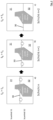
- Fig. 2
- drei Darstellungen zur Scanfeldanpassung, wobei in
Fig. 2a eine (erste) Schicht n, inFig. 2b eine weitere Schicht n+1 und inFig. 2c eine Schicht n+2 dargestellt ist. - Die in
Figur 1 dargestellte Vorrichtung 1 umfasst als wesentliche Komponenten eine Prozesskammer 2, in der ein Baucontainer 3 mit einer höhenverfahrbaren Bauplattform 4 angeordnet ist. Über der Bauplattform 4 ist eine Beschichteranordnung 5 angeordnet, durch welche Baumaterial 6 aus einer Dosierkammer 7 im Bereich des Baucontainers 3 in Form von dünnen Schichten aufgetragen werden kann. Über dem Baucontainer 3 ist in der Prozesskammer 2 eine Mehrzahl von Scannern 8a, 8b angeordnet, durch welche die Strahlung 9 einer Strahlungsquelle 10 in Form eines Lasers prozessgesteuert auf die Baumaterialschicht 11 gelenkt werden kann, um diese selektiv zu verfestigen. - Bei den aufgeführten Komponenten der Vorrichtung handelt es sich nur um die für die Erfindung wesentlichen Komponenten, selbstverständlich umfasst eine derartige Lasersinter oder Laserschmelzanlage eine Vielzahl weiterer Komponenten, die aber im Rahmen dieser Erfindung nicht erläutert werden müssen.
- Die Vorrichtung verfügt weiterhin über eine elektronische Erfassungseinheit 20, über die Bestrahlungszeiten bezogen auf jeden Scanner 8 und/oder bei einem Bestrahlungsschritt durch einen Scanner 8 erfassten Bestrahlungsflächen gesondert erfasst werden können und in einem elektronischen Speicher 21 abgelegt werden können.
- An den Speicher 21 ist eine elektronische Vergleichseinrichtung 22 angeschlossen, durch welche die abgespeicherten Bestrahlungszeitenwerte der einzelnen Scanner 8 miteinander verglichen werden können. Mit der Vergleichseinrichtung 22 ist eine Prozessoreinrichtung 23 verbunden, die im Falle von abweichenden Bestrahlungszeitenwerten der einzelnen Scanner 8 eine Neufestlegung der durch jeden einzelnen Scanner 8 zu belichtenden Oberflächenbereiche so berechnet, dass die Bestrahlungszeiten (oder die Bestrahlungsflächen) eines jeden einzelnen Scanners 8 flächenmäßig möglichst weit aneinander angeglichen sind.
- Weiterhin ist in
Figur 1 noch eine Eingabevorrichtung 25 mit einem Display 26 dargestellt, über die eine Bedienungsperson in den Bauprozess der Lasersinter- oder Laserschmelzvorrichtung 1 eingreifen kann. - Es sei kurz angemerkt, dass die Strahlung 9 der Strahlungsquelle 10 bei dem dargestellten Ausführungsbeispiel über einen Strahlteiler 15 geleitet wird, und von dort ein Fenster 16 im oberen Bereich der Prozesskammer 2 durchsetzt, um zu den Scannern 8a, 8b zu gelangen.
- Die Erfassungseinheit 20 umfasst an den Scannern oder diesen vorgeschalteten optischen Schaltern (Shuttern) Sensorelemente, die die Bestrahlungszeiten der Scanner 8 erfassen und als zu vergleichende Bestrahlungszeitenwerte T1 und T2 im Speicher 21 ablegen. Diese Werte werden in der Vergleichseinrichtung 22 miteinander verglichen, um durch den Prozessor eine Ansteuerungsoptimierung der Scanner zu ermöglichen.
- Dem Fachmann ist geläufig, dass zum einen die Bestrahlungszeitenerfassung durch eine Bestrahlungsflächenerfassung ersetzt oder ergänzt werden kann, dass der Speicher und der Vergleicher Teil eines elektronischen Systems zum Betrieb der Vorrichtung sein können und in einen Rechner oder Prozessor integriert sein können.
- In den
Figuren 2a - 2c ist nun näher dargelegt, wie die Optimierung der Scanfelder 31, 32 bzw. Bestrahlungsflächen bezogen auf die einzelnen Scanner 8a, 8b optimiert wird. - In
Figur 2a ist zunächst ein Zustand dargestellt, bei dem die zu erschmelzende Fläche des Scanfeldes 32 größer ist als des Scanfeldes 31. Aus diesem Grunde ist es zweckdienlich, die Grenze 30 zwischen dem Scanfeld 31 und dem Scanfeld 32 nach unten zu verschieben, sodass bei der nächsten Schicht n+1 gemäßFigur 2b bereits eine Annäherung der Scanfelder 31, 32 vorgenommen ist. - Dieser Vorgang wird so lange wiederholt, bis tatsächlich die Scanfelder 31 und 32 gleich groß sind, d. h. die Belichtungszeiten tA und tb sind aneinander angeglichen, sodass beide Scanner 8a und 8b zumindest weitgehend gleich ausgelastet sind.
- Ergibt die Vergleichsmessung der Bestrahlungszeiten oder Scanfeldgrößen, dass die Grenze 30 zwischen den Scanfeldern nicht verschoben werden muss, weil die Bestrahlungszeiten aneinander angeglichen sind, dann erfolgt eine Oszillation der Grenze 30 zwischen den Scanfeldern 31, 32, um eine Streifenbildung im Bauteil zu vermeiden.
-
- 1
- Vorrichtung
- 2
- Prozesskammer
- 3
- Baucontainer
- 4
- Bauplattenform
- 5
- Beschichteranordnung
- 6
- Baumaterial
- 7
- Dosierkammer
- 8
- Scanner
- 9
- Strahlung
- 10
- Strahlungsquelle
- 11
- Baumaterialschicht
- 15
- Strahlteiler
- 20
- Erfassungseinheit
- 21
- Speicher
- 22
- Vergleichseinrichtung
- 23
- Prozessoreinrichtung
- 25
- Eingabevorrichtung
- 26
- Display
- 30
- Grenze
- 31
- Scanfeld
- 32
- Scanfeld
Claims (4)
- Verfahren zur Belichtungssteuerung einer selektiven Lasersinter- oder Laserschmelzvorrichtung zum Herstellen von dreidimensionalen Objekten, mit folgenden Verfahrensschritten:- Bereitstellung einer selektiven Lasersinter- oder Laserschmelzvorrichtung (1), in welcher dreidimensionale Objekte durch aufeinanderfolgendes Verfestigen von Schichten eines mittels Strahlung verfestigbaren pulverartigen Baumaterials (6) an den dem jeweiligen Querschnitt des Objektes entsprechenden Stellen hergestellt werden können, wobei die bereitgestellte Vorrichtung (1) eine Bestrahlungseinrichtung zum Bestrahlen von Schichten des Baumaterials umfasst, die eine Mehrzahl von gesondert ansteuerbaren, gleichzeitig das Baumaterial bestrahlenden Scannern (8a, 8b) aufweist,
umfassend folgende Verfahrensschritte- gesonderte Erfassung der Bestrahlungszeiten eines jeden einzelnen Scanners (8a, 8b) und/oder der durch jeden einzelnen Scanner (8a, 8b) erfassten Bestrahlungsflächen in einem ersten Schritt und Abspeicherung der erfassten Bestrahlungszeiten und/oder Bestrahlungsflächen;- Vergleich der Bestrahlungszeiten und/oder Bestrahlungsflächen der einzelnen Scanner (8a, 8b) miteinander;- Neufestlegung der durch jeden einzelnen Scanner zu bestrahlenden Oberflächenbereiche einer Baumaterialschicht (11) derart, dass die Bestrahlungszeiten für jeden einzelnen Scanner (8a, 8b) möglichst aneinander angenähert sind und/oder die Bestrahlungsflächen eines jeden einzelnen Scanners (8a, 8b) flächenmäßig möglichst weit aneinander angeglichen sind, wobeidie Aufteilung der Scanfelder (31, 32) jeweils nach Verfestigung einer oder mehrerer Baumaterialschichten (11) dynamisch derart angepasst wird, dass die beim nachfolgenden Bestrahlungsdurchgang sich ergebende Belichtungszeit für jeden Scanner (8a, 8b) wenigstens annähernd gleich ist, wobei die Scanfelder (31, 32) für jeden Scanner (8a, 8b) in inkrementalen Schritten aneinander angepasst werden, wobeidie Grenze (30) zwischen den Scanfeldern (31, 32) oszilliert, falls der Vergleich der Bestrahlungszeiten oder -flächen betreffend einen jeden der Scanner (8a, 8b) keine Verschiebung der Scanfeld-Grenze (30) ergibt,dadurch gekennzeichnet, dassein Scanner (8a, 8b) im Scanfeld (31, 32) eines weiteren Scanners (8a, 8b) eine spannungsreduzierende Vorbelichtung eines Bestrahlungsabschnittes durchführt. - Verfahren nach Anspruch 1, dadurch gekennzeichnet, dass eine Bedienungsperson vor Beginn des Bauvorganges ausgehend von auslesbaren Steuerdaten der Scanner (8a, 8b) eine Voreinstellung der Größe der Scanfelder (31, 32) für jeden Scanner vornimmt.
- Verfahren nach einem der vorhergehenden Ansprüche, dadurch gekennzeichnet, dass die Grenze (30) zwischen den Scanfeldern (31, 32) eine Gerade ist.
- Verfahren nach einem der vorhergehenden Ansprüche, dadurch gekennzeichnet, dass dass die Belichtungszeiten einer Vorbelichtung ohne Einfluss auf die Scanfeldgrenzenverschiebung sind.
Priority Applications (1)
| Application Number | Priority Date | Filing Date | Title |
|---|---|---|---|
| EP18166334.5A EP3363621B1 (de) | 2014-11-12 | 2015-11-05 | Verfahren und vorrichtung zur belichtungssteuerung einer selektiven lasersinter- oder laserschmelzvorrichtung |
Applications Claiming Priority (2)
| Application Number | Priority Date | Filing Date | Title |
|---|---|---|---|
| DE102014016679.1A DE102014016679A1 (de) | 2014-11-12 | 2014-11-12 | Verfahren und Vorrichtung zur Belichtungssteuerung einer selektiven Lasersinter- oder Laserschmelzvorrichtung |
| PCT/EP2015/075832 WO2016075026A1 (de) | 2014-11-12 | 2015-11-05 | Verfahren und vorrichtung zur belichtungssteuerung einer selektiven lasersinter- oder laserschmelzvorrichtung |
Related Child Applications (2)
| Application Number | Title | Priority Date | Filing Date |
|---|---|---|---|
| EP18166334.5A Division EP3363621B1 (de) | 2014-11-12 | 2015-11-05 | Verfahren und vorrichtung zur belichtungssteuerung einer selektiven lasersinter- oder laserschmelzvorrichtung |
| EP18166334.5A Division-Into EP3363621B1 (de) | 2014-11-12 | 2015-11-05 | Verfahren und vorrichtung zur belichtungssteuerung einer selektiven lasersinter- oder laserschmelzvorrichtung |
Publications (3)
| Publication Number | Publication Date |
|---|---|
| EP3218168A1 EP3218168A1 (de) | 2017-09-20 |
| EP3218168B1 EP3218168B1 (de) | 2018-06-13 |
| EP3218168B2 true EP3218168B2 (de) | 2024-03-06 |
Family
ID=54705154
Family Applications (2)
| Application Number | Title | Priority Date | Filing Date |
|---|---|---|---|
| EP18166334.5A Active EP3363621B1 (de) | 2014-11-12 | 2015-11-05 | Verfahren und vorrichtung zur belichtungssteuerung einer selektiven lasersinter- oder laserschmelzvorrichtung |
| EP15801125.4A Active EP3218168B2 (de) | 2014-11-12 | 2015-11-05 | Verfahren und vorrichtung zur belichtungssteuerung einer selektiven lasersinter- oder laserschmelzvorrichtung |
Family Applications Before (1)
| Application Number | Title | Priority Date | Filing Date |
|---|---|---|---|
| EP18166334.5A Active EP3363621B1 (de) | 2014-11-12 | 2015-11-05 | Verfahren und vorrichtung zur belichtungssteuerung einer selektiven lasersinter- oder laserschmelzvorrichtung |
Country Status (7)
| Country | Link |
|---|---|
| US (3) | US10137633B2 (de) |
| EP (2) | EP3363621B1 (de) |
| JP (3) | JP6573670B2 (de) |
| CN (2) | CN110239090B (de) |
| DE (1) | DE102014016679A1 (de) |
| ES (1) | ES2686793T5 (de) |
| WO (1) | WO2016075026A1 (de) |
Families Citing this family (30)
| Publication number | Priority date | Publication date | Assignee | Title |
|---|---|---|---|---|
| CN106488819B (zh) | 2014-06-20 | 2018-06-22 | 维洛3D公司 | 用于三维打印的设备、系统和方法 |
| DE102014016679A1 (de) | 2014-11-12 | 2016-05-12 | Cl Schutzrechtsverwaltungs Gmbh | Verfahren und Vorrichtung zur Belichtungssteuerung einer selektiven Lasersinter- oder Laserschmelzvorrichtung |
| US9676145B2 (en) | 2015-11-06 | 2017-06-13 | Velo3D, Inc. | Adept three-dimensional printing |
| US10071422B2 (en) | 2015-12-10 | 2018-09-11 | Velo3D, Inc. | Skillful three-dimensional printing |
| CN108883575A (zh) | 2016-02-18 | 2018-11-23 | 维洛3D公司 | 准确的三维打印 |
| US11691343B2 (en) | 2016-06-29 | 2023-07-04 | Velo3D, Inc. | Three-dimensional printing and three-dimensional printers |
| US10286452B2 (en) | 2016-06-29 | 2019-05-14 | Velo3D, Inc. | Three-dimensional printing and three-dimensional printers |
| WO2018064349A1 (en) | 2016-09-30 | 2018-04-05 | Velo3D, Inc. | Three-dimensional objects and their formation |
| DE102016011801A1 (de) * | 2016-09-30 | 2018-04-05 | Eos Gmbh Electro Optical Systems | Verfahren zum Kalibrieren einer Vorrichtung zum Herstellen eines dreidimensionalen Objekts und zum Durchführen des Verfahrens ausgebildete Vorrichtung |
| WO2018128695A2 (en) | 2016-11-07 | 2018-07-12 | Velo3D, Inc. | Gas flow in three-dimensional printing |
| US10611092B2 (en) | 2017-01-05 | 2020-04-07 | Velo3D, Inc. | Optics in three-dimensional printing |
| US20180250744A1 (en) | 2017-03-02 | 2018-09-06 | Velo3D, Inc. | Three-dimensional printing of three-dimensional objects |
| US10449696B2 (en) | 2017-03-28 | 2019-10-22 | Velo3D, Inc. | Material manipulation in three-dimensional printing |
| US10272525B1 (en) | 2017-12-27 | 2019-04-30 | Velo3D, Inc. | Three-dimensional printing systems and methods of their use |
| US10144176B1 (en) | 2018-01-15 | 2018-12-04 | Velo3D, Inc. | Three-dimensional printing systems and methods of their use |
| DE102018203233A1 (de) | 2018-03-05 | 2019-09-05 | MTU Aero Engines AG | Belichtungsverfahren, Herstellungsverfahren und Vorrichtung zum selektiven Laserschmelzen |
| US10695867B2 (en) | 2018-03-08 | 2020-06-30 | General Electric Company | Controlling microstructure of selected range of layers of object during additive manufacture |
| US11426818B2 (en) | 2018-08-10 | 2022-08-30 | The Research Foundation for the State University | Additive manufacturing processes and additively manufactured products |
| EP3659784B1 (de) | 2018-11-28 | 2022-01-19 | Concept Laser GmbH | Verfahren zur generativen fertigung von mindestens einem dreidimensionalen objekt |
| JP7407832B2 (ja) | 2019-03-04 | 2024-01-04 | エスエルエム ソルーションズ グループ アーゲー | 制御方法、制御装置及び製造装置 |
| KR20230047214A (ko) | 2019-07-26 | 2023-04-06 | 벨로3디, 인크. | 3차원 물체 형상화에 대한 품질 보증 |
| CN110398200B (zh) * | 2019-08-29 | 2024-10-11 | 四川智能创新铸造有限公司 | 一种铸钢件缺陷坡口的体积检测装置及其检测方法 |
| JP6892957B1 (ja) * | 2020-07-22 | 2021-06-23 | 株式会社ソディック | 積層造形方法および積層造形システム |
| WO2022223411A1 (en) | 2021-04-21 | 2022-10-27 | SLM Solutions Group AG | Powder bed fusion additive manufacturing with load balancing for multiple beams |
| WO2022233860A1 (en) | 2021-05-07 | 2022-11-10 | SLM Solutions Group AG | Process chamber for an additive manufacturing apparatus and method for operating the process chamber |
| CN113715337B (zh) * | 2021-09-26 | 2023-10-27 | 上海联泰科技股份有限公司 | 控制装置、方法、3d打印方法及打印设备 |
| EP4239426A1 (de) | 2022-03-03 | 2023-09-06 | TRUMPF Additive Manufacturing Italia S.r.l. | Verfahren und planungsvorrichtung zur planung einer ortsselektiven bestrahlung eines arbeitsbereichs, computerprogramm, verfahren und vorrichtung zur additiven herstellung eines gegenstands aus einem pulvermaterial |
| DE102022108550A1 (de) | 2022-04-08 | 2023-10-12 | Trumpf Laser- Und Systemtechnik Gmbh | Verfahren zur schichtweisen Fertigung einer Vielzahl von Objekten und entsprechendes Planungsverfahren, mit volumenbasierter Aufteilung der Objekte auf Teilbereiche der Bauplattform |
| DE102024109301A1 (de) * | 2024-04-03 | 2025-10-09 | TRUMPF Laser- und Systemtechnik SE | Verfahren zur schichtweisen Fertigung von Bauteilen, Fertigungsvorrichtung sowie Computerprogrammprodukt |
| DE102024109300A1 (de) | 2024-04-03 | 2025-10-09 | TRUMPF Laser- und Systemtechnik SE | Verfahren zur schichtweisen Fertigung von Bauteilen, Fertigungsvorrichtung sowie Computerprogrammprodukt |
Citations (1)
| Publication number | Priority date | Publication date | Assignee | Title |
|---|---|---|---|---|
| JP2009006509A (ja) † | 2007-06-26 | 2009-01-15 | Panasonic Electric Works Co Ltd | 三次元形状造形物の製造方法及び製造装置 |
Family Cites Families (43)
| Publication number | Priority date | Publication date | Assignee | Title |
|---|---|---|---|---|
| US4469442A (en) | 1982-01-11 | 1984-09-04 | Japan Crown Cork Co., Ltd. | Detecting irregularities in a coating on a substrate |
| US4555179A (en) | 1982-11-08 | 1985-11-26 | John Langerholc | Detection and imaging of objects in scattering media by light irradiation |
| US5574215A (en) * | 1994-03-01 | 1996-11-12 | James W. Bunger & Associates, Inc. | Method for determining thermodynamic and molecular properties in the liquid phase |
| US5615013A (en) * | 1995-06-27 | 1997-03-25 | Virtek Vision Corp. | Galvanometer and camera system |
| US5724140A (en) | 1996-10-28 | 1998-03-03 | Ford Motor Company | Method and apparatus for determining the quality of flat glass sheet |
| CA2252308C (en) | 1998-10-30 | 2005-01-04 | Image Processing Systems, Inc. | Glass inspection system |
| JP2000263650A (ja) * | 1999-03-16 | 2000-09-26 | Hitachi Ltd | 光造形装置 |
| JP3515419B2 (ja) * | 1999-04-30 | 2004-04-05 | ティーエスコーポレーション株式会社 | 光学的立体造形方法および装置 |
| JP4582894B2 (ja) | 2000-11-16 | 2010-11-17 | ナブテスコ株式会社 | 光学的立体造形装置及び造形方法 |
| JP2003080604A (ja) * | 2001-09-10 | 2003-03-19 | Fuji Photo Film Co Ltd | 積層造形装置 |
| DE102004009126A1 (de) * | 2004-02-25 | 2005-09-22 | Bego Medical Ag | Verfahren und Einrichtung zum Erzeugen von Steuerungsdatensätzen für die Herstellung von Produkten durch Freiform-Sintern bzw. -Schmelzen sowie Vorrichtung für diese Herstellung |
| US7151603B2 (en) | 2004-04-30 | 2006-12-19 | Samsung Electronics Co. Ltd. | Overhead transparency clarity simulator |
| ES2385984T3 (es) * | 2004-05-05 | 2012-08-06 | Sign-Tronic Ag | Método para habilitar la transmisión de cantidades de energía prácticamente idénticas |
| DE102005024790A1 (de) * | 2005-05-26 | 2006-12-07 | Eos Gmbh Electro Optical Systems | Strahlungsheizung zum Heizen des Aufbaumaterials in einer Lasersintervorrichtung |
| US8666142B2 (en) * | 2008-11-18 | 2014-03-04 | Global Filtration Systems | System and method for manufacturing |
| EP2408586A1 (de) * | 2009-03-17 | 2012-01-25 | Wuxi Suntech Power Co., Ltd. | Bestrahlung einer platte unter verwendung mehrerer benachbart angeordneter strahlungsquellen |
| US8229204B2 (en) | 2009-06-29 | 2012-07-24 | Ecolab Inc. | Optical processing of surfaces to determine cleanliness |
| DE102010041284A1 (de) * | 2010-09-23 | 2012-03-29 | Siemens Aktiengesellschaft | Verfahren zum selektiven Lasersintern und für dieses Verfahren geeignete Anlage zum selektiven Lasersintern |
| US8687472B1 (en) | 2011-11-08 | 2014-04-01 | Marvell International Ltd. | Method and apparatus for determining the cleanliness of a lens in an optical disc drive |
| FR2984779B1 (fr) * | 2011-12-23 | 2015-06-19 | Michelin Soc Tech | Procede et appareil pour realiser des objets tridimensionnels |
| GB201205591D0 (en) * | 2012-03-29 | 2012-05-16 | Materials Solutions | Apparatus and methods for additive-layer manufacturing of an article |
| CN103358555A (zh) * | 2012-03-30 | 2013-10-23 | 通用电气公司 | 用于激光快速成型加工设备的多束激光扫描系统及方法 |
| DE102012014839A1 (de) * | 2012-07-27 | 2014-01-30 | Cl Schutzrechtsverwaltungs Gmbh | Vorrichtung zur Herstellung dreidimensionaler Objekte |
| FR2993805B1 (fr) * | 2012-07-27 | 2014-09-12 | Phenix Systems | Dispositif de fabrication d'objets tridimensionnels par couches superposees et procede de fabrication associe |
| DE102012014840A1 (de) * | 2012-07-27 | 2014-01-30 | Cl Schutzrechtsverwaltungs Gmbh | Vorrichtung zur Herstellung dreidimensionaler Objekte durch sukzessives Verfestigen von Schichten |
| US8913251B2 (en) | 2012-08-27 | 2014-12-16 | Canon Kabushiki Kaisha | Estimating material properties using speckle statistics |
| CN102818538B (zh) | 2012-09-14 | 2014-09-10 | 洛阳兰迪玻璃机器股份有限公司 | 基于调制玻璃线结构激光图像的检测系统 |
| US8836936B2 (en) | 2013-02-05 | 2014-09-16 | Shenzhen China Star Optoelectronics Technology Co., Ltd | Inspecting device for detecting appearance of debris on a surface of a glass substrate, inspecting apparatus and method for conducting inspection |
| WO2014144630A1 (en) | 2013-03-15 | 2014-09-18 | Matterfab Corp. | Cartridge for an additive manufacturing apparatus and method |
| DE102013208651A1 (de) * | 2013-05-10 | 2014-11-13 | Eos Gmbh Electro Optical Systems | Verfahren zum automatischen Kalibrieren einer Vorrichtung zum generativen Herstellen eines dreidimensionalen Objekts |
| WO2014199134A1 (en) | 2013-06-10 | 2014-12-18 | Renishaw Plc | Selective laser solidification apparatus and method |
| KR20150115596A (ko) * | 2014-04-04 | 2015-10-14 | 가부시키가이샤 마쓰우라 기카이 세이사쿠쇼 | 3차원 조형 장치 및 3차원 형상 조형물의 제조 방법 |
| DE102014005916A1 (de) | 2014-04-25 | 2015-10-29 | Cl Schutzrechtsverwaltungs Gmbh | Vorrichtung zum Herstellen von dreidimensionalen Objekten |
| CN103978307B (zh) * | 2014-04-30 | 2015-08-05 | 中国科学院化学研究所 | 一种用于精确控温的高分子材料紫外激光3d打印方法及装置 |
| US9682345B2 (en) | 2014-07-08 | 2017-06-20 | Particle Measuring Systems, Inc. | Method of treating a cleanroom enclosure |
| DE102014016679A1 (de) | 2014-11-12 | 2016-05-12 | Cl Schutzrechtsverwaltungs Gmbh | Verfahren und Vorrichtung zur Belichtungssteuerung einer selektiven Lasersinter- oder Laserschmelzvorrichtung |
| DE102016209933A1 (de) * | 2016-06-06 | 2017-12-07 | Eos Gmbh Electro Optical Systems | Vorrichtung und Verfahren zum generativen Herstellen eines dreidimensionalen Objekts |
| DE102017105056A1 (de) * | 2017-03-09 | 2018-09-13 | Cl Schutzrechtsverwaltungs Gmbh | Vorrichtung zur additiven Herstellung dreidimensionaler Objekte |
| US11084097B2 (en) * | 2017-06-23 | 2021-08-10 | Applied Materials, Inc. | Additive manufacturing with cell processing recipes |
| CN115319115B (zh) * | 2017-08-01 | 2026-01-06 | 戴弗根特技术有限公司 | 用于在增材制造操作期间测量辐射热能的系统和方法 |
| US10710307B2 (en) * | 2017-08-11 | 2020-07-14 | Applied Materials, Inc. | Temperature control for additive manufacturing |
| EP3636415B1 (de) | 2018-10-12 | 2023-01-04 | Concept Laser GmbH | Vorrichtung zur generativen fertigung dreidimensionaler objekte |
| EP4209332B1 (de) | 2018-11-21 | 2024-10-16 | Concept Laser GmbH | Bestrahlungsvorrichtung für eine vorrichtung zur generativen fertigung dreidimensionaler objekte |
-
2014
- 2014-11-12 DE DE102014016679.1A patent/DE102014016679A1/de active Pending
-
2015
- 2015-11-05 WO PCT/EP2015/075832 patent/WO2016075026A1/de not_active Ceased
- 2015-11-05 JP JP2017525577A patent/JP6573670B2/ja active Active
- 2015-11-05 CN CN201910355834.7A patent/CN110239090B/zh active Active
- 2015-11-05 US US15/526,711 patent/US10137633B2/en active Active
- 2015-11-05 EP EP18166334.5A patent/EP3363621B1/de active Active
- 2015-11-05 CN CN201580061317.9A patent/CN107107467B/zh active Active
- 2015-11-05 EP EP15801125.4A patent/EP3218168B2/de active Active
- 2015-11-05 ES ES15801125T patent/ES2686793T5/es active Active
-
2018
- 2018-06-13 US US16/007,813 patent/US10836103B2/en active Active
-
2019
- 2019-06-04 JP JP2019104310A patent/JP6873190B2/ja active Active
-
2020
- 2020-10-16 US US17/072,137 patent/US11945159B2/en active Active
-
2021
- 2021-04-19 JP JP2021070165A patent/JP7127896B2/ja active Active
Patent Citations (1)
| Publication number | Priority date | Publication date | Assignee | Title |
|---|---|---|---|---|
| JP2009006509A (ja) † | 2007-06-26 | 2009-01-15 | Panasonic Electric Works Co Ltd | 三次元形状造形物の製造方法及び製造装置 |
Also Published As
| Publication number | Publication date |
|---|---|
| JP7127896B2 (ja) | 2022-08-30 |
| CN110239090B (zh) | 2021-07-02 |
| WO2016075026A1 (de) | 2016-05-19 |
| EP3218168A1 (de) | 2017-09-20 |
| ES2686793T3 (es) | 2018-10-19 |
| US20210101333A1 (en) | 2021-04-08 |
| ES2686793T5 (es) | 2024-09-16 |
| CN107107467A (zh) | 2017-08-29 |
| EP3363621B1 (de) | 2023-05-03 |
| US11945159B2 (en) | 2024-04-02 |
| US20170320264A1 (en) | 2017-11-09 |
| CN107107467B (zh) | 2019-03-29 |
| JP2017537814A (ja) | 2017-12-21 |
| JP2021112916A (ja) | 2021-08-05 |
| US10137633B2 (en) | 2018-11-27 |
| JP2019137075A (ja) | 2019-08-22 |
| DE102014016679A1 (de) | 2016-05-12 |
| EP3218168B1 (de) | 2018-06-13 |
| EP3363621A1 (de) | 2018-08-22 |
| US20180370128A1 (en) | 2018-12-27 |
| CN110239090A (zh) | 2019-09-17 |
| JP6873190B2 (ja) | 2021-05-19 |
| JP6573670B2 (ja) | 2019-09-11 |
| US10836103B2 (en) | 2020-11-17 |
Similar Documents
| Publication | Publication Date | Title |
|---|---|---|
| EP3218168B2 (de) | Verfahren und vorrichtung zur belichtungssteuerung einer selektiven lasersinter- oder laserschmelzvorrichtung | |
| EP3062991B1 (de) | Verfahren zum herstellen eines dreidimensionalen bauteils | |
| EP3383624B1 (de) | Verfahren zum kalibrieren einer vorrichtung zum herstellen eines dreidimensionalen objekts | |
| WO2008049384A1 (de) | Vorrichtung zum herstellen eines dreidimensionalen objektes | |
| DE102013208651A1 (de) | Verfahren zum automatischen Kalibrieren einer Vorrichtung zum generativen Herstellen eines dreidimensionalen Objekts | |
| DE102013213547A1 (de) | Kalibriereinrichtung und Kalibrierverfahren für eine Vorrichtung zum schichtweisen Herstellen eines Objekts | |
| WO2016113253A1 (de) | Vorrichtung zur generativen herstellung dreidimensionaler bauteile | |
| WO2017174226A1 (de) | Verfahren zur kalibrierung wenigstens eines scannsystems, einer sls- oder slm-anlage | |
| DE102012021284B4 (de) | Vorrichtung und Verfahren zur schichtweisen Herstellung von Bauteilen mittels Photopolymerisation | |
| DE102017207264A1 (de) | Homogenisierung des Energieeintrags | |
| DE102015207306A1 (de) | Verfahren und Vorrichtung zum Herstellen eines dreidimensionalen Objekts | |
| WO2018172080A1 (de) | Belichtungsstrategie in mehrstrahl-am-systemen | |
| WO2017153187A1 (de) | Generatives schichtbauverfahren mit verbesserter detailauflösung und vorrichtung zur durchführung desselben | |
| EP3297813B1 (de) | Verfahren und vorrichtung zum herstellen eines dreidimensionalen objekts | |
| DE102011006941A1 (de) | Verfahren zum schichtweisen Herstellen eines Bauteils sowie Vorrichtung | |
| WO2018172079A1 (de) | Überlappoptimierung | |
| DE102011121568A1 (de) | Verfahren und Herstellung von dreidimensionalen Objekten durch aufeinanderfolgendes Verfestigen von Schichten eines pulverförmigen Aufbaumaterials | |
| DE102017207832A1 (de) | Positionsspezifischer Energieeintrag | |
| DE102016218951A1 (de) | Verfahren und Vorrichtung zur generativen Fertigung von Bauteilen auf einer Grundplatte mit Oberflächentopologie | |
| EP2979849B1 (de) | Vorrichtung zur herstellung dreidimensionaler objekte durch sukzessives verfestigen von schichten | |
| EP4045212A1 (de) | Verfahren zum betreiben einer einrichtung zur additiven herstellung eines dreidimensionalen objekts sowie verfahren zum erstellen eines prozessfensters zur durchführung des vorgenannten verfahrens | |
| EP3752346A1 (de) | Selektive nachbelichtung | |
| DE102016212171A1 (de) | Generatives Schichtbauverfahren und zugehörige Vorrichtung zur Herstellung von Objekten mit verminderter Porosität | |
| DE102024109299A1 (de) | Verfahren zum Überwachen einer Pulvermaterialschicht einer Fertigungsvorrichtung, sowie eine Fertigungsvorrichtung | |
| DE102023130787A1 (de) | Verfahren zum Überwachen einer Pulvermaterialschicht einer Fertigungsvorrichtung, sowie eine Fertigungsvorrichtung |
Legal Events
| Date | Code | Title | Description |
|---|---|---|---|
| STAA | Information on the status of an ep patent application or granted ep patent |
Free format text: STATUS: THE INTERNATIONAL PUBLICATION HAS BEEN MADE |
|
| PUAI | Public reference made under article 153(3) epc to a published international application that has entered the european phase |
Free format text: ORIGINAL CODE: 0009012 |
|
| STAA | Information on the status of an ep patent application or granted ep patent |
Free format text: STATUS: REQUEST FOR EXAMINATION WAS MADE |
|
| 17P | Request for examination filed |
Effective date: 20170512 |
|
| AK | Designated contracting states |
Kind code of ref document: A1 Designated state(s): AL AT BE BG CH CY CZ DE DK EE ES FI FR GB GR HR HU IE IS IT LI LT LU LV MC MK MT NL NO PL PT RO RS SE SI SK SM TR |
|
| AX | Request for extension of the european patent |
Extension state: BA ME |
|
| DAV | Request for validation of the european patent (deleted) | ||
| DAX | Request for extension of the european patent (deleted) | ||
| REG | Reference to a national code |
Ref country code: DE Ref legal event code: R079 Ref document number: 502015004721 Country of ref document: DE Free format text: PREVIOUS MAIN CLASS: B29C0067000000 Ipc: B29C0064153000 |
|
| GRAP | Despatch of communication of intention to grant a patent |
Free format text: ORIGINAL CODE: EPIDOSNIGR1 |
|
| STAA | Information on the status of an ep patent application or granted ep patent |
Free format text: STATUS: GRANT OF PATENT IS INTENDED |
|
| RIC1 | Information provided on ipc code assigned before grant |
Ipc: B33Y 50/02 20150101ALI20180309BHEP Ipc: B29C 64/153 20170101AFI20180309BHEP Ipc: B29C 64/386 20170101ALI20180309BHEP Ipc: B22F 3/105 20060101ALI20180309BHEP Ipc: B33Y 30/00 20150101ALI20180309BHEP |
|
| INTG | Intention to grant announced |
Effective date: 20180404 |
|
| GRAS | Grant fee paid |
Free format text: ORIGINAL CODE: EPIDOSNIGR3 |
|
| GRAA | (expected) grant |
Free format text: ORIGINAL CODE: 0009210 |
|
| STAA | Information on the status of an ep patent application or granted ep patent |
Free format text: STATUS: THE PATENT HAS BEEN GRANTED |
|
| AK | Designated contracting states |
Kind code of ref document: B1 Designated state(s): AL AT BE BG CH CY CZ DE DK EE ES FI FR GB GR HR HU IE IS IT LI LT LU LV MC MK MT NL NO PL PT RO RS SE SI SK SM TR |
|
| REG | Reference to a national code |
Ref country code: GB Ref legal event code: FG4D Free format text: NOT ENGLISH |
|
| REG | Reference to a national code |
Ref country code: CH Ref legal event code: EP Ref country code: AT Ref legal event code: REF Ref document number: 1008018 Country of ref document: AT Kind code of ref document: T Effective date: 20180615 |
|
| REG | Reference to a national code |
Ref country code: IE Ref legal event code: FG4D Free format text: LANGUAGE OF EP DOCUMENT: GERMAN |
|
| REG | Reference to a national code |
Ref country code: DE Ref legal event code: R096 Ref document number: 502015004721 Country of ref document: DE |
|
| REG | Reference to a national code |
Ref country code: CH Ref legal event code: PK Free format text: BERICHTIGUNGEN |
|
| RIN2 | Information on inventor provided after grant (corrected) |
Inventor name: HERZOG, FRANK Inventor name: BECHMANN, FLORIAN Inventor name: LIPPERT, MARKUS Inventor name: HOCH, JOHANNA |
|
| REG | Reference to a national code |
Ref country code: NL Ref legal event code: MP Effective date: 20180613 |
|
| REG | Reference to a national code |
Ref country code: ES Ref legal event code: FG2A Ref document number: 2686793 Country of ref document: ES Kind code of ref document: T3 Effective date: 20181019 |
|
| REG | Reference to a national code |
Ref country code: FR Ref legal event code: PLFP Year of fee payment: 4 |
|
| REG | Reference to a national code |
Ref country code: LT Ref legal event code: MG4D |
|
| PG25 | Lapsed in a contracting state [announced via postgrant information from national office to epo] |
Ref country code: SE Free format text: LAPSE BECAUSE OF FAILURE TO SUBMIT A TRANSLATION OF THE DESCRIPTION OR TO PAY THE FEE WITHIN THE PRESCRIBED TIME-LIMIT Effective date: 20180613 Ref country code: NO Free format text: LAPSE BECAUSE OF FAILURE TO SUBMIT A TRANSLATION OF THE DESCRIPTION OR TO PAY THE FEE WITHIN THE PRESCRIBED TIME-LIMIT Effective date: 20180913 Ref country code: BG Free format text: LAPSE BECAUSE OF FAILURE TO SUBMIT A TRANSLATION OF THE DESCRIPTION OR TO PAY THE FEE WITHIN THE PRESCRIBED TIME-LIMIT Effective date: 20180913 Ref country code: FI Free format text: LAPSE BECAUSE OF FAILURE TO SUBMIT A TRANSLATION OF THE DESCRIPTION OR TO PAY THE FEE WITHIN THE PRESCRIBED TIME-LIMIT Effective date: 20180613 Ref country code: LT Free format text: LAPSE BECAUSE OF FAILURE TO SUBMIT A TRANSLATION OF THE DESCRIPTION OR TO PAY THE FEE WITHIN THE PRESCRIBED TIME-LIMIT Effective date: 20180613 Ref country code: CY Free format text: LAPSE BECAUSE OF FAILURE TO SUBMIT A TRANSLATION OF THE DESCRIPTION OR TO PAY THE FEE WITHIN THE PRESCRIBED TIME-LIMIT Effective date: 20180613 |
|
| PG25 | Lapsed in a contracting state [announced via postgrant information from national office to epo] |
Ref country code: RS Free format text: LAPSE BECAUSE OF FAILURE TO SUBMIT A TRANSLATION OF THE DESCRIPTION OR TO PAY THE FEE WITHIN THE PRESCRIBED TIME-LIMIT Effective date: 20180613 Ref country code: HR Free format text: LAPSE BECAUSE OF FAILURE TO SUBMIT A TRANSLATION OF THE DESCRIPTION OR TO PAY THE FEE WITHIN THE PRESCRIBED TIME-LIMIT Effective date: 20180613 Ref country code: GR Free format text: LAPSE BECAUSE OF FAILURE TO SUBMIT A TRANSLATION OF THE DESCRIPTION OR TO PAY THE FEE WITHIN THE PRESCRIBED TIME-LIMIT Effective date: 20180914 Ref country code: LV Free format text: LAPSE BECAUSE OF FAILURE TO SUBMIT A TRANSLATION OF THE DESCRIPTION OR TO PAY THE FEE WITHIN THE PRESCRIBED TIME-LIMIT Effective date: 20180613 |
|
| PG25 | Lapsed in a contracting state [announced via postgrant information from national office to epo] |
Ref country code: NL Free format text: LAPSE BECAUSE OF FAILURE TO SUBMIT A TRANSLATION OF THE DESCRIPTION OR TO PAY THE FEE WITHIN THE PRESCRIBED TIME-LIMIT Effective date: 20180613 |
|
| PG25 | Lapsed in a contracting state [announced via postgrant information from national office to epo] |
Ref country code: CZ Free format text: LAPSE BECAUSE OF FAILURE TO SUBMIT A TRANSLATION OF THE DESCRIPTION OR TO PAY THE FEE WITHIN THE PRESCRIBED TIME-LIMIT Effective date: 20180613 Ref country code: RO Free format text: LAPSE BECAUSE OF FAILURE TO SUBMIT A TRANSLATION OF THE DESCRIPTION OR TO PAY THE FEE WITHIN THE PRESCRIBED TIME-LIMIT Effective date: 20180613 Ref country code: IS Free format text: LAPSE BECAUSE OF FAILURE TO SUBMIT A TRANSLATION OF THE DESCRIPTION OR TO PAY THE FEE WITHIN THE PRESCRIBED TIME-LIMIT Effective date: 20181013 Ref country code: EE Free format text: LAPSE BECAUSE OF FAILURE TO SUBMIT A TRANSLATION OF THE DESCRIPTION OR TO PAY THE FEE WITHIN THE PRESCRIBED TIME-LIMIT Effective date: 20180613 Ref country code: PL Free format text: LAPSE BECAUSE OF FAILURE TO SUBMIT A TRANSLATION OF THE DESCRIPTION OR TO PAY THE FEE WITHIN THE PRESCRIBED TIME-LIMIT Effective date: 20180613 Ref country code: SK Free format text: LAPSE BECAUSE OF FAILURE TO SUBMIT A TRANSLATION OF THE DESCRIPTION OR TO PAY THE FEE WITHIN THE PRESCRIBED TIME-LIMIT Effective date: 20180613 |
|
| PG25 | Lapsed in a contracting state [announced via postgrant information from national office to epo] |
Ref country code: SM Free format text: LAPSE BECAUSE OF FAILURE TO SUBMIT A TRANSLATION OF THE DESCRIPTION OR TO PAY THE FEE WITHIN THE PRESCRIBED TIME-LIMIT Effective date: 20180613 |
|
| REG | Reference to a national code |
Ref country code: DE Ref legal event code: R026 Ref document number: 502015004721 Country of ref document: DE |
|
| PLBI | Opposition filed |
Free format text: ORIGINAL CODE: 0009260 |
|
| PLAX | Notice of opposition and request to file observation + time limit sent |
Free format text: ORIGINAL CODE: EPIDOSNOBS2 |
|
| 26 | Opposition filed |
Opponent name: EOS GMBH ELECTRO OPTICAL SYSTEMS Effective date: 20190312 Opponent name: SLM SOLUTIONS GROUP AG Effective date: 20190313 |
|
| PG25 | Lapsed in a contracting state [announced via postgrant information from national office to epo] |
Ref country code: DK Free format text: LAPSE BECAUSE OF FAILURE TO SUBMIT A TRANSLATION OF THE DESCRIPTION OR TO PAY THE FEE WITHIN THE PRESCRIBED TIME-LIMIT Effective date: 20180613 |
|
| REG | Reference to a national code |
Ref country code: CH Ref legal event code: PL |
|
| PG25 | Lapsed in a contracting state [announced via postgrant information from national office to epo] |
Ref country code: LU Free format text: LAPSE BECAUSE OF NON-PAYMENT OF DUE FEES Effective date: 20181105 Ref country code: MC Free format text: LAPSE BECAUSE OF FAILURE TO SUBMIT A TRANSLATION OF THE DESCRIPTION OR TO PAY THE FEE WITHIN THE PRESCRIBED TIME-LIMIT Effective date: 20180613 |
|
| PLBB | Reply of patent proprietor to notice(s) of opposition received |
Free format text: ORIGINAL CODE: EPIDOSNOBS3 |
|
| REG | Reference to a national code |
Ref country code: BE Ref legal event code: MM Effective date: 20181130 |
|
| REG | Reference to a national code |
Ref country code: IE Ref legal event code: MM4A |
|
| PG25 | Lapsed in a contracting state [announced via postgrant information from national office to epo] |
Ref country code: CH Free format text: LAPSE BECAUSE OF NON-PAYMENT OF DUE FEES Effective date: 20181130 Ref country code: LI Free format text: LAPSE BECAUSE OF NON-PAYMENT OF DUE FEES Effective date: 20181130 |
|
| PG25 | Lapsed in a contracting state [announced via postgrant information from national office to epo] |
Ref country code: IE Free format text: LAPSE BECAUSE OF NON-PAYMENT OF DUE FEES Effective date: 20181105 |
|
| PG25 | Lapsed in a contracting state [announced via postgrant information from national office to epo] |
Ref country code: AL Free format text: LAPSE BECAUSE OF FAILURE TO SUBMIT A TRANSLATION OF THE DESCRIPTION OR TO PAY THE FEE WITHIN THE PRESCRIBED TIME-LIMIT Effective date: 20180613 Ref country code: BE Free format text: LAPSE BECAUSE OF NON-PAYMENT OF DUE FEES Effective date: 20181130 |
|
| PG25 | Lapsed in a contracting state [announced via postgrant information from national office to epo] |
Ref country code: MT Free format text: LAPSE BECAUSE OF FAILURE TO SUBMIT A TRANSLATION OF THE DESCRIPTION OR TO PAY THE FEE WITHIN THE PRESCRIBED TIME-LIMIT Effective date: 20180613 |
|
| PG25 | Lapsed in a contracting state [announced via postgrant information from national office to epo] |
Ref country code: TR Free format text: LAPSE BECAUSE OF FAILURE TO SUBMIT A TRANSLATION OF THE DESCRIPTION OR TO PAY THE FEE WITHIN THE PRESCRIBED TIME-LIMIT Effective date: 20180613 |
|
| PG25 | Lapsed in a contracting state [announced via postgrant information from national office to epo] |
Ref country code: PT Free format text: LAPSE BECAUSE OF FAILURE TO SUBMIT A TRANSLATION OF THE DESCRIPTION OR TO PAY THE FEE WITHIN THE PRESCRIBED TIME-LIMIT Effective date: 20180613 |
|
| PG25 | Lapsed in a contracting state [announced via postgrant information from national office to epo] |
Ref country code: MK Free format text: LAPSE BECAUSE OF NON-PAYMENT OF DUE FEES Effective date: 20180613 Ref country code: HU Free format text: LAPSE BECAUSE OF FAILURE TO SUBMIT A TRANSLATION OF THE DESCRIPTION OR TO PAY THE FEE WITHIN THE PRESCRIBED TIME-LIMIT; INVALID AB INITIO Effective date: 20151105 |
|
| PG25 | Lapsed in a contracting state [announced via postgrant information from national office to epo] |
Ref country code: SI Free format text: LAPSE BECAUSE OF NON-PAYMENT OF DUE FEES Effective date: 20181105 |
|
| APBM | Appeal reference recorded |
Free format text: ORIGINAL CODE: EPIDOSNREFNO |
|
| APBP | Date of receipt of notice of appeal recorded |
Free format text: ORIGINAL CODE: EPIDOSNNOA2O |
|
| APAH | Appeal reference modified |
Free format text: ORIGINAL CODE: EPIDOSCREFNO |
|
| APBQ | Date of receipt of statement of grounds of appeal recorded |
Free format text: ORIGINAL CODE: EPIDOSNNOA3O |
|
| REG | Reference to a national code |
Ref country code: AT Ref legal event code: MM01 Ref document number: 1008018 Country of ref document: AT Kind code of ref document: T Effective date: 20201105 |
|
| PG25 | Lapsed in a contracting state [announced via postgrant information from national office to epo] |
Ref country code: AT Free format text: LAPSE BECAUSE OF NON-PAYMENT OF DUE FEES Effective date: 20201105 |
|
| REG | Reference to a national code |
Ref country code: DE Ref legal event code: R081 Ref document number: 502015004721 Country of ref document: DE Owner name: CONCEPT LASER GMBH, DE Free format text: FORMER OWNER: CL SCHUTZRECHTSVERWALTUNGS GMBH, 96215 LICHTENFELS, DE |
|
| REG | Reference to a national code |
Ref country code: GB Ref legal event code: 732E Free format text: REGISTERED BETWEEN 20230406 AND 20230412 |
|
| REG | Reference to a national code |
Ref country code: ES Ref legal event code: PC2A Owner name: CONCEPT LASER GMBH Effective date: 20230609 |
|
| P01 | Opt-out of the competence of the unified patent court (upc) registered |
Effective date: 20230516 |
|
| P02 | Opt-out of the competence of the unified patent court (upc) changed |
Effective date: 20230605 |
|
| PLAB | Opposition data, opponent's data or that of the opponent's representative modified |
Free format text: ORIGINAL CODE: 0009299OPPO |
|
| APBU | Appeal procedure closed |
Free format text: ORIGINAL CODE: EPIDOSNNOA9O |
|
| R26 | Opposition filed (corrected) |
Opponent name: NIKON SLM SOLUTIONS AG Effective date: 20190313 |
|
| RAP2 | Party data changed (patent owner data changed or rights of a patent transferred) |
Owner name: CONCEPT LASER GMBH |
|
| PUAH | Patent maintained in amended form |
Free format text: ORIGINAL CODE: 0009272 |
|
| STAA | Information on the status of an ep patent application or granted ep patent |
Free format text: STATUS: PATENT MAINTAINED AS AMENDED |
|
| 27A | Patent maintained in amended form |
Effective date: 20240306 |
|
| AK | Designated contracting states |
Kind code of ref document: B2 Designated state(s): AL AT BE BG CH CY CZ DE DK EE ES FI FR GB GR HR HU IE IS IT LI LT LU LV MC MK MT NL NO PL PT RO RS SE SI SK SM TR |
|
| REG | Reference to a national code |
Ref country code: DE Ref legal event code: R102 Ref document number: 502015004721 Country of ref document: DE |
|
| REG | Reference to a national code |
Ref country code: ES Ref legal event code: DC2A Ref document number: 2686793 Country of ref document: ES Kind code of ref document: T5 Effective date: 20240916 |
|
| PGFP | Annual fee paid to national office [announced via postgrant information from national office to epo] |
Ref country code: DE Payment date: 20251022 Year of fee payment: 11 |
|
| PGFP | Annual fee paid to national office [announced via postgrant information from national office to epo] |
Ref country code: GB Payment date: 20251023 Year of fee payment: 11 |
|
| PGFP | Annual fee paid to national office [announced via postgrant information from national office to epo] |
Ref country code: IT Payment date: 20251022 Year of fee payment: 11 |
|
| PGFP | Annual fee paid to national office [announced via postgrant information from national office to epo] |
Ref country code: FR Payment date: 20251022 Year of fee payment: 11 |
|
| PGFP | Annual fee paid to national office [announced via postgrant information from national office to epo] |
Ref country code: ES Payment date: 20251201 Year of fee payment: 11 |