EP3217538A1 - Verfahren und vorrichtung zur überprüfung der funktion einer ansteuerschaltung eines gleichstrommotors - Google Patents
Verfahren und vorrichtung zur überprüfung der funktion einer ansteuerschaltung eines gleichstrommotors Download PDFInfo
- Publication number
- EP3217538A1 EP3217538A1 EP17000337.0A EP17000337A EP3217538A1 EP 3217538 A1 EP3217538 A1 EP 3217538A1 EP 17000337 A EP17000337 A EP 17000337A EP 3217538 A1 EP3217538 A1 EP 3217538A1
- Authority
- EP
- European Patent Office
- Prior art keywords
- motor
- drive circuit
- voltage
- potential
- display
- Prior art date
- Legal status (The legal status is an assumption and is not a legal conclusion. Google has not performed a legal analysis and makes no representation as to the accuracy of the status listed.)
- Granted
Links
Images

Classifications
-
- H—ELECTRICITY
- H02—GENERATION; CONVERSION OR DISTRIBUTION OF ELECTRIC POWER
- H02P—CONTROL OR REGULATION OF ELECTRIC MOTORS, ELECTRIC GENERATORS OR DYNAMO-ELECTRIC CONVERTERS; CONTROLLING TRANSFORMERS, REACTORS OR CHOKE COILS
- H02P29/00—Arrangements for regulating or controlling electric motors, appropriate for both AC and DC motors
- H02P29/02—Providing protection against overload without automatic interruption of supply
- H02P29/024—Detecting a fault condition, e.g. short circuit, locked rotor, open circuit or loss of load
- H02P29/0241—Detecting a fault condition, e.g. short circuit, locked rotor, open circuit or loss of load the fault being an overvoltage
-
- G—PHYSICS
- G05—CONTROLLING; REGULATING
- G05B—CONTROL OR REGULATING SYSTEMS IN GENERAL; FUNCTIONAL ELEMENTS OF SUCH SYSTEMS; MONITORING OR TESTING ARRANGEMENTS FOR SUCH SYSTEMS OR ELEMENTS
- G05B23/00—Testing or monitoring of control systems or parts thereof
- G05B23/02—Electric testing or monitoring
- G05B23/0205—Electric testing or monitoring by means of a monitoring system capable of detecting and responding to faults
- G05B23/0259—Electric testing or monitoring by means of a monitoring system capable of detecting and responding to faults characterized by the response to fault detection
-
- H—ELECTRICITY
- H02—GENERATION; CONVERSION OR DISTRIBUTION OF ELECTRIC POWER
- H02P—CONTROL OR REGULATION OF ELECTRIC MOTORS, ELECTRIC GENERATORS OR DYNAMO-ELECTRIC CONVERTERS; CONTROLLING TRANSFORMERS, REACTORS OR CHOKE COILS
- H02P29/00—Arrangements for regulating or controlling electric motors, appropriate for both AC and DC motors
- H02P29/02—Providing protection against overload without automatic interruption of supply
- H02P29/024—Detecting a fault condition, e.g. short circuit, locked rotor, open circuit or loss of load
-
- H—ELECTRICITY
- H02—GENERATION; CONVERSION OR DISTRIBUTION OF ELECTRIC POWER
- H02P—CONTROL OR REGULATION OF ELECTRIC MOTORS, ELECTRIC GENERATORS OR DYNAMO-ELECTRIC CONVERTERS; CONTROLLING TRANSFORMERS, REACTORS OR CHOKE COILS
- H02P7/00—Arrangements for regulating or controlling the speed or torque of electric DC motors
- H02P7/06—Arrangements for regulating or controlling the speed or torque of electric DC motors for regulating or controlling an individual DC dynamo-electric motor by varying field or armature current
- H02P7/18—Arrangements for regulating or controlling the speed or torque of electric DC motors for regulating or controlling an individual DC dynamo-electric motor by varying field or armature current by master control with auxiliary power
- H02P7/24—Arrangements for regulating or controlling the speed or torque of electric DC motors for regulating or controlling an individual DC dynamo-electric motor by varying field or armature current by master control with auxiliary power using discharge tubes or semiconductor devices
- H02P7/28—Arrangements for regulating or controlling the speed or torque of electric DC motors for regulating or controlling an individual DC dynamo-electric motor by varying field or armature current by master control with auxiliary power using discharge tubes or semiconductor devices using semiconductor devices
- H02P7/285—Arrangements for regulating or controlling the speed or torque of electric DC motors for regulating or controlling an individual DC dynamo-electric motor by varying field or armature current by master control with auxiliary power using discharge tubes or semiconductor devices using semiconductor devices controlling armature supply only
Definitions
- the invention relates to a method and a device for checking the function of a drive circuit of a DC motor, wherein electrical voltage terminals of the DC motor are connected via the drive circuit to a voltage source and between the drive circuit and the voltage source, an operating switch for starting the DC motor is arranged via the drive circuit.
- the supply voltage of a voltage source is switched via the drive circuit according to predetermined parameters on the DC motor, to regulate this in the power and / or speed.
- the drive circuit uses a control arrangement, preferably a so-called pulse width modulation, in which the DC motor voltage pulses of variable width are supplied. In accordance with the pulse width of the voltage pulses, a rotational speed is established on the DC motor.
- a drive circuit uses electronic switching elements such as transistors, thyristors, MOSFETs or the like components in order to adjust the pulse width over the entire operating range of the DC motor depending on predetermined parameters. If an electronic component fails due to a defect, essentially two states can occur.
- the DC motor can no longer be operated; If the defective component is conductive, the DC motor can also rotate without the PWM control, with the applied battery voltage acting unregulated on the DC motor.
- the electronic fault of the drive circuit can not be determined by the user readily.
- the invention has for its object to provide a method and apparatus for testing the operation of a drive circuit before commissioning a DC motor to detect an electronic fault of the drive circuit early.
- the potential prevailing there is checked for at least one voltage connection of the DC motor. If the drive circuit is operating correctly, the potential would have to be low or zero, since the DC motor is stationary and therefore can not generate any EMF generator voltage that can be tapped off at the voltage connections. If, on the other hand, a potential is applied to the voltage connection of the DC motor during the check, which is above a predetermined limit value, then it can be assumed that there is an error since the motor is already rotating before activation by the drive circuit. In this case, a display is driven to indicate to the user the malfunction of the drive circuit.
- the checking of the potential on the voltage connection of the DC motor takes place within a time window which is necessary for the initialization of the drive circuit.
- the potential on the voltage terminal of the DC motor is checked and evaluated.
- the time window of the initialization is in a range of 5 to 500 milliseconds.
- test device for detecting the potential on the voltage connection to be put into operation simultaneously with the switching on of the operating switch.
- the limit value below which a proper function of the drive circuit can be assumed is expediently derived from a potential course permissible at a start of the DC motor on the voltage terminals. If the voltage detected on a voltage connection of the DC motor is above this limit value, it can be assumed that there is an impermissible potential profile and thus there is an error in the drive circuit.
- a visual display is driven.
- An acoustic indication may be appropriate.
- the device for checking the operation of a drive circuit of a DC motor comprises a test device for detecting the potential on the voltage terminal of the DC motor within a time window after the start of the initialization of the drive circuit and before the startup of the DC motor.
- the test device is connected to at least one measuring line with a voltage connection of the DC motor and controls a display when the potential applied to the measuring line is above a predetermined limit.
- test apparatus and the drive device are arranged in a common housing and in particular on a common board.
- the supply voltage of the voltage source can be selected to be greater than the permissible operating voltage of the DC motor.
- the display controlled by the test device is advantageously an optical display, in particular an LED.
- the circuit arrangement in Fig. 1 shows a device for checking a drive circuit 10 for a DC motor 1.
- the DC motor 1 is a DC motor with collector brushes 2, 3rd
- an operating voltage U B is applied to the electrical voltage terminals 4, 5, which are connected to the collector brushes 2, 3, an operating voltage U B is applied.
- the operating voltage U B is provided by the drive circuit 10, which is connected via an operating switch 12 to a voltage source 7.
- the voltage source 7 is formed by a battery pack 8, the individual cells 6 form a cell network.
- the supply voltage Uv of the voltage source 7 is connected via the operating switch 12 to the drive circuit 10.
- the drive circuit 10 operates on the principle of pulse width modulation.
- the supply voltage Uv of the voltage source 7 may be greater than the allowable operating voltage U B of the DC motor 1.
- About the pulse width modulation adjustment of the operating voltage U B is easily possible. If the power output stages of the drive circuit are conductively destroyed in such a PWM control, the DC motor 1 also rotates without function of the PWM control. The user can not easily recognize the error. In case of failure, the operating voltage U B can be at the level of the battery voltage.
- the contact 11 of the preferably designed as a microswitch operating switch 12 is closed and the supply voltage Uv on input terminals 13, 15 of the drive circuit 10 is connected.
- the circuit arrangement further comprises a test device 20, which is connected to at least one measuring line 21, 22 with one of the voltage terminals 4, 5 of the DC motor 1.
- a measuring line 21 is connected to the voltage terminal 4 of the collector brush 2 and a measuring line 22 to the voltage terminal 5 of the collector brush 3.
- the test apparatus 20 is connected via the input terminals 13, 15 to the supply voltage Uv and has a first output 14, which drives a display 30.
- the display 30 is an optical display, in particular an LED 31.
- test apparatus 20 is connected to the drive circuit 10.
- test apparatus 20 and the drive device 10 are arranged in a common housing 25.
- the drive circuit 10 and the test device 20 are arranged on a common board 24.
- the supply voltage Uv of the battery pack 8 is expediently greater than the permissible operating voltage U B of the DC motor 1 is provided.
- the battery pack 8 consists in particular of lithium-based single cells 6.
- the upper diagram in Fig. 2 shows the state of the operation switch 12; in the "off” state, the contact 11 is open; in the state “on” the contact 11 is closed.
- the initialization of the drive circuit 10 includes the proper startup of a microprocessor arranged in the drive circuit, the execution of test routines and the assumption of a predetermined, defined electrical starting position. This initialization of the drive circuit 10 takes 5 to 500 milliseconds.
- the lower diagram shows the generator voltage U (EMF) of the DC motor 1 between the voltage terminals 4 and 5 again.
- the potential 40 is below a limit value 41; the drive circuit 10 operates correctly.
- the current consumption I of the DC motor 1 can also be checked, as shown in the middle diagram in FIG Fig. 2 is shown. If the current consumption lies below a limit value 43 within the time window ⁇ T of the initialization of the drive circuit 10, this works correctly.
- Fig. 2 shows that at time t 1, the operation switch 30 is turned on and in the time window .DELTA.T initialization until time t 2, neither the potential of the generator voltage U (EMF) exceeds a predetermined limit 41, nor given a lying above the limit value 43 current consumption of the DC motor 1 is. The drive circuit operates properly. The display 30 is not activated.
- EMF generator voltage
- the operating switch 12 is switched on at the time t 1 ; with the switching on of the operating switch 12, the supply voltage Uv is applied to the input terminals 13, 15 of the drive circuit 10, whereupon the drive circuit starts its initialization.
- the initialization is the time window .DELTA.T assigned to the time t 2 .
- the potential 40 on the voltage terminal 4, 5 of the DC motor 1 is checked.
- the test device 20 controls the display 30 at.
- the display is advantageously an optical display, in particular an LED 31.
- the verification of the potential of the generator voltage U (EMF) within the time window .DELTA.T of the initialization takes place. It may be sufficient to carry out the check over a smaller period of time than the time window ⁇ T of the initialization.
- the smaller time span is expediently within the time window ⁇ T of the initialization, which lies in a range of 5 to 500 milliseconds.
- test device 20 is - as well as the drive circuit 10 - applied simultaneously with the turning on of the operating switch 12 to the supply voltage Uv and put into operation.
- the determination of the limit value 41 of the generator voltage EMK can expediently be derived from a permissible potential profile at the start of the DC motor 1.
- the limit value 43 of the permissible motor current IM can be derived from a permissible current profile at a start of the DC motor 1.
Landscapes
- Engineering & Computer Science (AREA)
- Power Engineering (AREA)
- Physics & Mathematics (AREA)
- General Physics & Mathematics (AREA)
- Automation & Control Theory (AREA)
- Control Of Direct Current Motors (AREA)
Abstract
Description
- Die Erfindung betrifft ein Verfahren und eine Vorrichtung zur Überprüfung der Funktion einer Ansteuerschaltung eines Gleichstrommotors, wobei elektrische Spannungsanschlüsse des Gleichstrommotors über die Ansteuerschaltung mit einer Spannungsquelle verbunden sind und zwischen der Ansteuerschaltung und der Spannungsquelle ein Betriebsschalter zur Inbetriebnahme des Gleichstrommotors über die Ansteuerschaltung angeordnet ist.
- Derartige Vorrichtungen sind bekannt. Die Versorgungsspannung einer Spannungsquelle wird über die Ansteuerschaltung entsprechend vorgegebenen Parametern auf den Gleichstrommotor geschaltet, um diesen in der Leistung und/oder der Drehzahl zu regeln. Hierzu nutzt die Ansteuerschaltung eine Regelanordnung, vorzugsweise eine sogenannte Pulsweitenmodulation, bei der dem Gleichstrommotor Spannungsimpulse variabler Breite zugeführt werden. Entsprechend der Pulsbreite der Spannungsimpulse stellt sich eine Drehzahl am Gleichstrommotor ein.
- Eine Ansteuerschaltung nutzt elektronische Schaltglieder wie Transistoren, Thyristoren, MOSFET's oder dergleichen Bauteile, um in Abhängigkeit vorgegebener Parameter die Pulsweite über den gesamten Betriebsbereich des Gleichstrommotors einstellen zu können. Fällt ein elektronisches Bauteil wegen Defekt aus, können im Wesentlichen zwei Zustände auftreten.
- Trennt das defekte Bauteil den Stromkreis permanent, wird der Gleichstrommotor nicht mehr betrieben werden können; ist das defekte Bauteil leitend, kann sich der Gleichstrommotor auch ohne die PWM-Ansteuerung drehen, wobei die angelegte Akkuspannung ungeregelt auf den Gleichstrommotor wirkt. Die elektronische Störung der Ansteuerschaltung kann vom Benutzer nicht ohne weiteres festgestellt werden.
- Der Erfindung liegt die Aufgabe zugrunde, ein Verfahren und eine Vorrichtung zur Funktionsprüfung einer Ansteuerschaltung vor Inbetriebnahme eines Gleichstrommotors anzugeben, um eine elektronische Störung der Ansteuerschaltung frühzeitig zu erkennen.
- Die Aufgabe wird mit einem Verfahren nach dem Anspruch 1 gelöst. Eine Vorrichtung zur Durchführung des Verfahrens ist im Anspruch 7 angegeben.
- Bei dem Verfahren zur Überprüfung der Funktion einer Ansteuerschaltung eines Gleichstrommotors wird davon ausgegangen, dass das System zunächst spannungsfrei ist. Mit Einschalten des Betriebsschalters wird die Versorgungsspannung der Spannungsquelle auf die Ansteuerschaltung geschaltet, wodurch diese initialisiert wird.
- Mit Beginn der Initialisierung der Ansteuerschaltung und vor einer Inbetriebnahme des Gleichstrommotors durch die Ansteuerschaltung wird auf zumindest einem Spannungsanschluss des Gleichstrommotors das dort herrschende Potential überprüft. Bei ordnungsgemäß arbeitender Ansteuerschaltung müsste das Potential gering bzw. Null sein, da der Gleichstrommotor steht und somit auch keine EMK-Generatorspannung erzeugen kann, die an den Spannungsanschlüssen abgegriffen werden kann. Liegt hingegen bei der Überprüfung ein Potential auf dem Spannungsanschluss des Gleichstrommotors an, welches oberhalb eines vorgegebenen Grenzwertes liegt, so kann von einem Fehler ausgegangen werden, da der Motor vor Ansteuerung durch die Ansteuerschaltung bereits dreht. In diesem Fall wird eine Anzeige angesteuert, um dem Benutzer die Fehlfunktion der Ansteuerschaltung anzuzeigen.
- Vorteilhaft erfolgt die Überprüfung des Potentials auf dem Spannungsanschluss des Gleichstrommotors innerhalb eines Zeitfensters, das zur Initialisierung der Ansteuerschaltung notwendig ist. Während also die Ansteuerschaltung initialisiert wird, wird das Potential auf dem Spannungsanschluss des Gleichstrommotors überprüft und ausgewertet.
- Das Zeitfenster der Initialisierung liegt in einem Bereich von 5 bis 500 Millisekunden.
- Um das erfindungsgemäße Verfahren auszuführen, ist vorgesehen, gleichzeitig mit dem Einschalten des Betriebsschalters eine Prüfvorrichtung zur Erfassung des Potentials auf dem Spannungsanschluss in Betrieb zu nehmen.
- Der Grenzwert, unterhalb dessen von einer ordnungsgemäßen Funktion der Ansteuerschaltung ausgegangen werden kann, ist zweckmäßig von einem bei einem Start des Gleichstrommotors zulässigen Potentialverlauf auf den Spannungsanschlüssen abgeleitet. Liegt die auf einem Spannungsanschluss des Gleichstrommotors festgestellte Spannung oberhalb dieses Grenzwertes, kann davon ausgegangen werden, dass ein unzulässiger Potentialverlauf vorliegt und somit ein Fehler in der Ansteuerschaltung gegeben ist.
- Als zweckmäßige Anzeige für die Fehlerhaftigkeit der Ansteuerschaltung wird eine optische Anzeige angesteuert. Eine akustische Anzeige kann zweckmäßig sein.
- Die Vorrichtung zur Überprüfung der Funktion einer Ansteuerschaltung eines Gleichstrommotors umfasst eine Prüfvorrichtung zur Erfassung des Potentials auf dem Spannungsanschluss des Gleichstrommotors innerhalb eines Zeitfensters nach Beginn der Initialisierung der Ansteuerschaltung und vor der Inbetriebnahme des Gleichstrommotors. Die Prüfvorrichtung ist mit zumindest einer Messleitung mit einem Spannungsanschluss des Gleichstrommotors verbunden und steuert eine Anzeige an, wenn das auf der Messleitung anliegende Potential oberhalb eines vorgegebenen Grenzwertes liegt.
- Zweckmäßig sind die Prüfvorrichtung und die Ansteuervorrichtung in einem gemeinsamen Gehäuse und insbesondere auf einer gemeinsamen Platine angeordnet.
- Da zwischen der Spannungsquelle und dem Gleichstrommotor eine Ansteuerschaltung vorgesehen ist, die zweckmäßig nach dem Prinzip der Pulsweitenmodulation arbeitet, kann die Versorgungsspannung der Spannungsquelle größer als die zulässige Betriebsspannung des Gleichstrommotors gewählt werden.
- Die von der Prüfvorrichtung angesteuerte Anzeige ist vorteilhaft eine optische Anzeige, insbesondere eine LED.
- Weitere Merkmale der Erfindung ergeben sich aus den weiteren Ansprüchen, der Beschreibung und der Zeichnung, in der ein nachfolgend im Einzelnen beschriebenes Ausführungsbeispiel der Erfindung dargestellt ist. Es zeigen:
- Fig. 1
- in schematischer Darstellung eine Schaltungsanordnung einer Vorrichtung zur Überprüfung der Funktion einer Ansteuerschaltung eines Gleichstrommotors,
- Fig. 2
- in schematischer Darstellung ein Diagramm zur Darstellung des Verlaufs des Motorstroms und der rückwirkenden Generatorspannung (EMK - elektromagnetische Kraft) bei einer ordnungsgemäß arbeitenden Ansteuerschaltung,
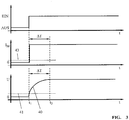
- Fig. 3
- eine Darstellung gemäß
Fig. 2 bei fehlerhaft arbeitender Ansteuerschaltung. - Die Schaltungsanordnung in
Fig. 1 zeigt eine Vorrichtung zur Überprüfung einer Ansteuerschaltung 10 für einen Gleichstrommotor 1. Der Gleichstrommotor 1 ist ein Gleichstrommotor mit Kollektorbürsten 2, 3. - An die elektrischen Spannungsanschlüsse 4, 5, die mit den Kollektorbürsten 2, 3 verbunden sind, ist eine Betriebsspannung UB angelegt. Die Betriebsspannung UB wird von der Ansteuerschaltung 10 bereitgestellt, die über einen Betriebsschalter 12 mit einer Spannungsquelle 7 verbunden ist.
- Die Spannungsquelle 7 ist von einem Akkupack 8 gebildet, dessen Einzelzellen 6 einen Zellverbund bilden. Die Versorgungsspannung Uv der Spannungsquelle 7 ist über den Betriebsschalter 12 auf die Ansteuerschaltung 10 geschaltet.
- Die Ansteuerschaltung 10 arbeitet nach dem Prinzip der Pulsweitenmodulation. Die Versorgungsspannung Uv der Spannungsquelle 7 kann größer sein als die zulässige Betriebsspannung UB des Gleichstrommotors 1. Über die Pulsweitenmodulation ist eine Einstellung der Betriebsspannung UB leicht möglich. Werden bei einer derartigen PWM-Ansteuerung die Leistungsendstufen der Ansteuerschaltung leitend zerstört, dreht der Gleichstrommotor 1 auch ohne Funktion der PWM-Ansteuerung. Der Benutzer kann den Fehler ohne weiteres nicht erkennen. Im Fehlerfall kann die Betriebsspannung UB auf dem Niveau der Akkuspannung liegen.
- Mit Niederdrücken des Betätigungsstiftes 9 wird der Kontakt 11 des vorzugsweise als Mikroschalter ausgebildeten Betriebsschalters 12 geschlossen und die Versorgungsspannung Uv auf Eingangsklemmen 13, 15 der Ansteuerschaltung 10 geschaltet.
- Die Schaltungsanordnung umfasst ferner eine Prüfvorrichtung 20, die mit zumindest einer Messleitung 21, 22 mit einem der Spannungsanschlüsse 4, 5 des Gleichstrommotors 1 verbunden ist. Im gezeigten Ausführungsbeispiel ist eine Messleitung 21 mit dem Spannungsanschluss 4 der Kollektorbürste 2 und eine Messleitung 22 mit dem Spannungsanschluss 5 der Kollektorbürste 3 verbunden. Die Prüfvorrichtung 20 ist über die Eingangsklemmen 13, 15 mit der Versorgungsspannung Uv verbunden und hat einen ersten Ausgang 14, der eine Anzeige 30 ansteuert. Im gezeigten Ausführungsbeispiel ist die Anzeige 30 eine optische Anzeige, insbesondere eine LED 31.
- Über eine Signalleitung 16 ist die Prüfvorrichtung 20 mit der Ansteuerschaltung 10 verbunden.
- Wie in
Fig. 1 dargestellt, sind die Prüfvorrichtung 20 und die Ansteuervorrichtung 10 in einem gemeinsamen Gehäuse 25 angeordnet. Vorzugsweise sind die Ansteuerschaltung 10 und die Prüfvorrichtung 20 auf einer gemeinsamen Platine 24 angeordnet. - Die Versorgungsspannung Uv des Akkupacks 8 ist zweckmäßig größer als die zulässige Betriebsspannung UB des Gleichstrommotors 1 vorgesehen. Der Akkupack 8 besteht insbesondere aus auf Lithium basierenden Einzelzellen 6.
- Arbeitet die Ansteuerschaltung 10 zwischen der Spannungsquelle 7 und dem Gleichstrommotor 1 ordnungsgemäß, ergeben sich die in
Fig. 2 dargestellten Diagramme. - Das obere Diagramm in
Fig. 2 zeigt den Zustand des Betriebsschalters 12; im Zustand "Aus" ist der Kontakt 11 offen; im Zustand "Ein" ist der Kontakt 11 geschlossen. - Bei geschlossenem Kontakt 11 wird die Versorgungsspannung Uv auf die Eingangsklemmen 13, 15 der Ansteuerschaltung geschaltet. Mit dem Anliegen der Spannung an die Ansteuerschaltung 10 wird diese initialisiert.
- Die Initialisierung der Ansteuerschaltung 10 umfasst das ordnungsgemäße Hochlaufen eines in der Ansteuerschaltung angeordneten Mikroprozessors, das Abarbeiten von Prüfroutinen und das Einnehmen einer vorgegebenen, definierten elektrischen Ausgangsstellung. Diese Initialisierung der Ansteuerschaltung 10 benötigt 5 bis 500 Millisekunden.
- Innerhalb eines Zeitfensters ΔT nach dem Beginn der Initialisierung der Ansteuerschaltung und vor der Inbetriebnahme des Gleichstrommotors 1 wird mittels der Prüfvorrichtung 20 das Potential 40 auf zumindest einem der Spannungsanschlüsse 4, 5 des Gleichstrommotors überprüft, wie es im unteren Diagramm in
Fig. 2 dargestellt ist. Im gezeigten Ausführungsbeispiel wird das Potential 40 zwischen den Spannungsanschlüssen 4, 5 des Gleichstrommotors 1 abgefragt. - In der Darstellung der
Fig. 2 gibt das untere Diagramm die Generatorspannung U (EMK) des Gleichstrommotors 1 zwischen den Spannungsanschlüssen 4 und 5 wieder. Das Potential 40 liegt unterhalb eines Grenzwertes 41; die Ansteuerschaltung 10 arbeitet korrekt. - Alternativ oder zusätzlich zur Überprüfung der rückwirkenden Generatorspannung U kann auch die Stromaufnahme I des Gleichstrommotors 1 überprüft werden, wie es im mittleren Diagramm in
Fig. 2 dargestellt ist. Liegt die Stromaufnahme unterhalb eines Grenzwertes 43 innerhalb des Zeitfensters ΔT der Initialisierung der Ansteuerschaltung 10, arbeitet diese korrekt. -
Fig. 2 zeigt, dass zum Zeitpunkt t1 der Betriebsschalter 30 eingeschaltet wird und im Zeitfenster ΔT der Initialisierung bis zum Zeitpunkt t2 weder das Potential der Generatorspannung U (EMK) einen vorgegebenen Grenzwert 41 übersteigt, noch eine über dem Grenzwert 43 liegende Stromaufnahme des Gleichstrommotors 1 gegeben ist. Die Ansteuerschaltung arbeitet ordnungsgemäß. Die Anzeige 30 wird nicht angesteuert. - In der Darstellung nach
Fig. 3 wird im Zeitpunkt t1 der Betriebsschalter 12 eingeschaltet; mit dem Einschalten des Betriebsschalters 12 wird die Versorgungsspannung Uv an die Eingangsklemmen 13, 15 der Ansteuerschaltung 10 gelegt, worauf die Ansteuerschaltung ihre Initialisierung startet. Der Initialisierung ist das Zeitfenster ΔT bis zum Zeitpunkt t2 zugeordnet. Mit dem Beginn der Initialisierung der Ansteuerschaltung 10 und vor der Inbetriebnahme des Gleichstrommotors 1 wird das Potential 40 auf dem Spannungsanschluss 4, 5 des Gleichstrommotors 1 überprüft. WieFig. 3 zeigt, ist innerhalb des Zeitfensters ΔT das Potential 40 der Generatorspannung über den Grenzwert 41 angestiegen. Da das Potential 40 oberhalb des Grenzwertes 41 liegt, steuert die Prüfvorrichtung 20 die Anzeige 30 an. Vorteilhaft ist die Anzeige eine optische Anzeige, insbesondere eine LED 31. - Wie in den
Figuren 2 und3 dargestellt, erfolgt die Überprüfung des Potentials der Generatorspannung U (EMK) innerhalb des Zeitfensters ΔT der Initialisierung. Es kann ausreichend sein, die Überprüfung über eine kleinere Zeitspanne als das Zeitfenster ΔT der Initialisierung auszuführen. Die kleinere Zeitspanne liegt dabei zweckmäßig innerhalb des Zeitfensters ΔT der Initialisierung, welches in einem Bereich von 5 bis 500 Millisekunden liegt. - Die Prüfvorrichtung 20 wird - ebenso wie die Ansteuerschaltung 10 - gleichzeitig mit dem Einschalten des Betriebsschalters 12 an die Versorgungspannung Uv angelegt und in Betrieb genommen.
- Die Bestimmung des Grenzwertes 41 der Generatorspannung EMK kann zweckmäßig von einem beim Start des Gleichstrommotors 1 zulässigen Potentialverlauf abgeleitet werden. In gleicher Weise kann der Grenzwert 43 des zulässigen Motorstroms IM von einem zulässigen Stromverlauf bei einem Start des Gleichstrommotors 1 abgeleitet werden.
Claims (11)
- Verfahren zur Überprüfung der Funktion einer Ansteuerschaltung (10) eines Gleichstrommotors (1), wobei elektrische Spannungsanschlüsse (4, 5) des Gleichstrommotors (1) über die Ansteuerschaltung (10) mit einer Spannungsquelle (7) verbunden sind, und mit einem zwischen der Ansteuerschaltung (10) und der Spannungsquelle (7) angeordnetem Betriebsschalter (12) zur Inbetriebnahme des Gleichstrommotors (1) über die Ansteuerschaltung (10),
gekennzeichnet durch die Verfahrensschritte:- Einschalten des Betriebsschalters (12),- Initialisieren der Ansteuerschaltung (10) mit dem Einschalten des Betriebsschalters (12),- Überprüfen eines Potentials (40) auf einem Spannungsanschluss (4, 5) des Gleichstrommotors (1) innerhalb eines Zeitfensters (ΔT) nach Beginn der Initialisierung der Ansteuerschaltung (10) und vor der Inbetriebnahme des Gleichstrommotors (1),- Ansteuern einer Anzeige (30), wenn bei der Überprüfung ein Potential (40) auf dem Spannungsanschluss (4, 5) des Gleichstrommotors (1) festgestellt wird, welches oberhalb eines vorgegebenen Grenzwertes (41) liegt. - Verfahren nach Anspruch 1,
dadurch gekennzeichnet, dass die Überprüfung des Potentials (40) auf dem Spannungsanschluss (4, 5) innerhalb eines Zeitfensters (ΔT) der Initialisierung erfolgt. - Verfahren nach Anspruch 1,
dadurch gekennzeichnet, dass das Zeitfenster (ΔT) in einem Bereich von 5 bis 500 Millisekunden liegt. - Verfahren nach Anspruch 1,
dadurch gekennzeichnet, dass mit dem Einschalten des Betriebsschalters (12) eine Prüfvorrichtung (20) zur Erfassung des Potentials (40) auf dem Spannungsanschluss (4, 5) in Betrieb genommen wird. - Verfahren nach Anspruch 1,
dadurch gekennzeichnet, dass der Grenzwert (41) von einem bei einem Start des Gleichstrommotors (1) zulässigen Potentialverlauf abgeleitet ist. - Verfahren nach Anspruch 1,
dadurch gekennzeichnet, dass als Anzeige (30) eine optische Anzeige angesteuert wird. - Vorrichtung zur Überprüfung der Funktion einer Ansteuerschaltung (10) eines Gleichstrommotors (1),wobei elektrische Spannungsanschlüsse (4, 5) des Gleichstrommotors (1) über die Ansteuerschaltung (10) mit einer Spannungsquelle (7) verbunden sind, und mit einem zwischen der Ansteuerschaltung (10) und der Spannungsquelle (7) angeordneten Betriebsschalter (12) zur Inbetriebnahme des Gleichstrommotors (1) über die Ansteuerschaltung (10),
dadurch gekennzeichnet, dass eine Prüfvorrichtung (20) zur Erfassung des Potentials (40) auf dem Spannungsanschluss (4, 5) des Gleichstrommotors (1) innerhalb eines Zeitfensters (ΔT) nach Beginn der Initialisierung der Ansteuerschaltung (10) und vor der Inbetriebnahme des Gleichstrommotors (1) vorgesehen ist, wobei die Prüfvorrichtung (20) mit zumindest einer Messleitung (21, 22) mit einem Spannungsanschluss (4, 5) des Gleichstrommotors (1) verbunden ist, und dass die Prüf-vorrichtung (20) eine Anzeige (30) ansteuert, wenn das auf der Messleitung (21, 22) anliegende Potential (40) oberhalb eines vorgegebenen Grenzwertes (41) liegt. - Vorrichtung nach Anspruch 7,
dadurch gekennzeichnet, dass die Prüfvorrichtung (20) und die Ansteuervorrichtung (10) in einem gemeinsamen Gehäuse (25) und insbesondere auf einer gemeinsamen Platine (24) angeordnet sind. - Vorrichtung nach Anspruch 7,
dadurch gekennzeichnet, dass die Versorgungsspannung (UV) der Spannungsquelle (7) größer ist als die zulässige Betriebsspannung (UB) des Gleichstrommotors (1). - Vorrichtung nach Anspruch 7,
dadurch gekennzeichnet, dass die Anzeige (30) eine optische Anzeige, insbesondere eine LED (31) ist. - Vorrichtung nach Anspruch 7,
dadurch gekennzeichnet, dass die Spannungsquelle (7) ein Akkupack (8) ist, insbesondere ein Akkupack (8) aus auf Lithium basierenden Einzelzellen (6) ist.
Applications Claiming Priority (1)
| Application Number | Priority Date | Filing Date | Title |
|---|---|---|---|
| DE102016002740.1A DE102016002740A1 (de) | 2016-03-07 | 2016-03-07 | Verfahren und Vorrichtung zur Überprüfung der Funktion einer Ansteuerschaltung eines Gleichstrommotors |
Publications (2)
| Publication Number | Publication Date |
|---|---|
| EP3217538A1 true EP3217538A1 (de) | 2017-09-13 |
| EP3217538B1 EP3217538B1 (de) | 2021-07-07 |
Family
ID=58261468
Family Applications (1)
| Application Number | Title | Priority Date | Filing Date |
|---|---|---|---|
| EP17000337.0A Active EP3217538B1 (de) | 2016-03-07 | 2017-03-06 | Verfahren und vorrichtung zur überprüfung der funktion einer ansteuerschaltung eines gleichstrommotors |
Country Status (4)
| Country | Link |
|---|---|
| US (1) | US10014816B2 (de) |
| EP (1) | EP3217538B1 (de) |
| CN (1) | CN107168274B (de) |
| DE (1) | DE102016002740A1 (de) |
Citations (3)
| Publication number | Priority date | Publication date | Assignee | Title |
|---|---|---|---|---|
| JPH06343289A (ja) * | 1993-05-28 | 1994-12-13 | Nisshinbo Ind Inc | モータ異常検出装置 |
| EP2164169A1 (de) * | 2007-04-16 | 2010-03-17 | Mitsubishi Electric Corporation | Elektromotor-steuervorrichtung |
| US20120313561A1 (en) * | 2010-02-24 | 2012-12-13 | Advics Co., Ltd. | Motor drive unit |
Family Cites Families (4)
| Publication number | Priority date | Publication date | Assignee | Title |
|---|---|---|---|---|
| US6794836B2 (en) * | 2001-02-06 | 2004-09-21 | Invacare Corporation | Electric motor drive controller with voltage control circuit operative in different modes |
| DE102011015977A1 (de) * | 2011-04-04 | 2012-10-04 | Andreas Stihl Ag & Co. Kg | Verfahren zur Inbetriebnahme einer elektronischen Ansteuerschaltung eines elektrischen Motors und Schaltungsanordnung hierzu |
| DE102011086626A1 (de) * | 2011-11-18 | 2013-05-23 | Continental Automotive Gmbh | Integrierte Schaltung zum Schalten von Lasten, Schaltungsanordnung mit einer integrierten Schaltung und einer angeschlossenen Last und Verfahren zum Betreiben einer solchen Schaltungsanordnung |
| JP5882691B2 (ja) * | 2011-11-21 | 2016-03-09 | サンデンホールディングス株式会社 | インバータシステムの故障検知装置 |
-
2016
- 2016-03-07 DE DE102016002740.1A patent/DE102016002740A1/de not_active Withdrawn
-
2017
- 2017-03-06 EP EP17000337.0A patent/EP3217538B1/de active Active
- 2017-03-07 US US15/452,468 patent/US10014816B2/en active Active
- 2017-03-07 CN CN201710131127.0A patent/CN107168274B/zh active Active
Patent Citations (3)
| Publication number | Priority date | Publication date | Assignee | Title |
|---|---|---|---|---|
| JPH06343289A (ja) * | 1993-05-28 | 1994-12-13 | Nisshinbo Ind Inc | モータ異常検出装置 |
| EP2164169A1 (de) * | 2007-04-16 | 2010-03-17 | Mitsubishi Electric Corporation | Elektromotor-steuervorrichtung |
| US20120313561A1 (en) * | 2010-02-24 | 2012-12-13 | Advics Co., Ltd. | Motor drive unit |
Also Published As
| Publication number | Publication date |
|---|---|
| DE102016002740A1 (de) | 2017-09-07 |
| US10014816B2 (en) | 2018-07-03 |
| CN107168274B (zh) | 2021-09-24 |
| US20170257053A1 (en) | 2017-09-07 |
| EP3217538B1 (de) | 2021-07-07 |
| CN107168274A (zh) | 2017-09-15 |
Similar Documents
| Publication | Publication Date | Title |
|---|---|---|
| EP2715932B1 (de) | Verfahren und vorrichtung zum betrieb eines bürstenlosen motors | |
| DE112014006373B4 (de) | Elektromotor mit Bremse | |
| EP2509214B1 (de) | Verfahren zur Inbetriebnahme einer elektronischen Ansteuerschaltung eines elektrischen Motors und Schaltungsanordnung hierzu | |
| DE102006052423A1 (de) | Servolenkungsvorrichtung | |
| EP0152770A1 (de) | Überwachte Regeleinrichtung | |
| EP2714489A2 (de) | Verfahren und vorrichtung zum betrieb eines bürstenlosen motors | |
| EP2446529B1 (de) | Notverstelleinrichtung für blattverstellsysteme von windenergieanlagen | |
| DE03022913T1 (de) | Schaltervorrichtung | |
| DE102017211219A1 (de) | Verfahren und Vorrichtung zum Betreiben einer elektrischen Maschine, insbesondere eines Lenkunterstützungsantriebs | |
| EP2548038A1 (de) | Verfahren und vorrichtung zur detektion einer blockierung oder schwergängigkeit eines gleichstrommotors | |
| EP3217538B1 (de) | Verfahren und vorrichtung zur überprüfung der funktion einer ansteuerschaltung eines gleichstrommotors | |
| DE102005051762A1 (de) | Vorrichtung zum steuerbaren Herstellen einer Schaltverbindung | |
| DE2917529C2 (de) | Verfahren und Prüfgerät zur Gewährleistung der Betriebssicherheit von mit elektrischen Stellantrieben versehenen Armaturen | |
| EP3585639A1 (de) | Vorrichtung und verfahren zum betreiben eines kraftfahrzeugs, kraftfahrzeug | |
| DE20321134U1 (de) | Elektronische Vorrichtung zum Steuern und Antreiben einer Pumpe für Haushaltsgeräte | |
| DE102005054693B4 (de) | Steuer- bzw. Regelsystem zum Antrieb eines Tores oder einer Türe | |
| EP3305142A1 (de) | Kaffeemaschine | |
| DE102005004174A1 (de) | Verfahren zur Diagnose einer Kraftfahrzeugbatterie | |
| EP1333346B1 (de) | Verfahren und Einrichtung zur Fehlerdiagnose an gesteuerten elektrischen Antrieben | |
| DE102008034619A1 (de) | Verfahren und elektrische Schaltung zur Erzeugung elektrischer Energie | |
| DE102013212379B3 (de) | Verfahren zum Betreiben einer Mikrorechnervorrichtung | |
| DE102022121605A1 (de) | Invertervorrichtung und Verfahren zum Betreiben der Invertervorrichtung | |
| DE3444655A1 (de) | Schaltung fuer eine einphasige geraetestromversorgung aus einem dreiphasennetz | |
| DE202017102254U1 (de) | Leistungsversorgungsanordnung | |
| WO2025124755A1 (de) | Verfahren zur überwachung einer umschaltung eines laststufenschalters mittels antriebseinheit und antriebseinheit |
Legal Events
| Date | Code | Title | Description |
|---|---|---|---|
| PUAI | Public reference made under article 153(3) epc to a published international application that has entered the european phase |
Free format text: ORIGINAL CODE: 0009012 |
|
| STAA | Information on the status of an ep patent application or granted ep patent |
Free format text: STATUS: THE APPLICATION HAS BEEN PUBLISHED |
|
| AK | Designated contracting states |
Kind code of ref document: A1 Designated state(s): AL AT BE BG CH CY CZ DE DK EE ES FI FR GB GR HR HU IE IS IT LI LT LU LV MC MK MT NL NO PL PT RO RS SE SI SK SM TR |
|
| AX | Request for extension of the european patent |
Extension state: BA ME |
|
| STAA | Information on the status of an ep patent application or granted ep patent |
Free format text: STATUS: REQUEST FOR EXAMINATION WAS MADE |
|
| 17P | Request for examination filed |
Effective date: 20180312 |
|
| RBV | Designated contracting states (corrected) |
Designated state(s): AL AT BE BG CH CY CZ DE DK EE ES FI FR GB GR HR HU IE IS IT LI LT LU LV MC MK MT NL NO PL PT RO RS SE SI SK SM TR |
|
| GRAP | Despatch of communication of intention to grant a patent |
Free format text: ORIGINAL CODE: EPIDOSNIGR1 |
|
| STAA | Information on the status of an ep patent application or granted ep patent |
Free format text: STATUS: GRANT OF PATENT IS INTENDED |
|
| INTG | Intention to grant announced |
Effective date: 20210208 |
|
| GRAS | Grant fee paid |
Free format text: ORIGINAL CODE: EPIDOSNIGR3 |
|
| GRAA | (expected) grant |
Free format text: ORIGINAL CODE: 0009210 |
|
| STAA | Information on the status of an ep patent application or granted ep patent |
Free format text: STATUS: THE PATENT HAS BEEN GRANTED |
|
| AK | Designated contracting states |
Kind code of ref document: B1 Designated state(s): AL AT BE BG CH CY CZ DE DK EE ES FI FR GB GR HR HU IE IS IT LI LT LU LV MC MK MT NL NO PL PT RO RS SE SI SK SM TR |
|
| REG | Reference to a national code |
Ref country code: GB Ref legal event code: FG4D Free format text: NOT ENGLISH |
|
| REG | Reference to a national code |
Ref country code: AT Ref legal event code: REF Ref document number: 1409556 Country of ref document: AT Kind code of ref document: T Effective date: 20210715 |
|
| REG | Reference to a national code |
Ref country code: DE Ref legal event code: R096 Ref document number: 502017010814 Country of ref document: DE |
|
| REG | Reference to a national code |
Ref country code: IE Ref legal event code: FG4D Free format text: LANGUAGE OF EP DOCUMENT: GERMAN |
|
| REG | Reference to a national code |
Ref country code: LT Ref legal event code: MG9D |
|
| REG | Reference to a national code |
Ref country code: NL Ref legal event code: MP Effective date: 20210707 |
|
| PG25 | Lapsed in a contracting state [announced via postgrant information from national office to epo] |
Ref country code: SE Free format text: LAPSE BECAUSE OF FAILURE TO SUBMIT A TRANSLATION OF THE DESCRIPTION OR TO PAY THE FEE WITHIN THE PRESCRIBED TIME-LIMIT Effective date: 20210707 Ref country code: RS Free format text: LAPSE BECAUSE OF FAILURE TO SUBMIT A TRANSLATION OF THE DESCRIPTION OR TO PAY THE FEE WITHIN THE PRESCRIBED TIME-LIMIT Effective date: 20210707 Ref country code: ES Free format text: LAPSE BECAUSE OF FAILURE TO SUBMIT A TRANSLATION OF THE DESCRIPTION OR TO PAY THE FEE WITHIN THE PRESCRIBED TIME-LIMIT Effective date: 20210707 Ref country code: FI Free format text: LAPSE BECAUSE OF FAILURE TO SUBMIT A TRANSLATION OF THE DESCRIPTION OR TO PAY THE FEE WITHIN THE PRESCRIBED TIME-LIMIT Effective date: 20210707 Ref country code: HR Free format text: LAPSE BECAUSE OF FAILURE TO SUBMIT A TRANSLATION OF THE DESCRIPTION OR TO PAY THE FEE WITHIN THE PRESCRIBED TIME-LIMIT Effective date: 20210707 Ref country code: NO Free format text: LAPSE BECAUSE OF FAILURE TO SUBMIT A TRANSLATION OF THE DESCRIPTION OR TO PAY THE FEE WITHIN THE PRESCRIBED TIME-LIMIT Effective date: 20211007 Ref country code: NL Free format text: LAPSE BECAUSE OF FAILURE TO SUBMIT A TRANSLATION OF THE DESCRIPTION OR TO PAY THE FEE WITHIN THE PRESCRIBED TIME-LIMIT Effective date: 20210707 Ref country code: PT Free format text: LAPSE BECAUSE OF FAILURE TO SUBMIT A TRANSLATION OF THE DESCRIPTION OR TO PAY THE FEE WITHIN THE PRESCRIBED TIME-LIMIT Effective date: 20211108 Ref country code: BG Free format text: LAPSE BECAUSE OF FAILURE TO SUBMIT A TRANSLATION OF THE DESCRIPTION OR TO PAY THE FEE WITHIN THE PRESCRIBED TIME-LIMIT Effective date: 20211007 Ref country code: LT Free format text: LAPSE BECAUSE OF FAILURE TO SUBMIT A TRANSLATION OF THE DESCRIPTION OR TO PAY THE FEE WITHIN THE PRESCRIBED TIME-LIMIT Effective date: 20210707 |
|
| PG25 | Lapsed in a contracting state [announced via postgrant information from national office to epo] |
Ref country code: PL Free format text: LAPSE BECAUSE OF FAILURE TO SUBMIT A TRANSLATION OF THE DESCRIPTION OR TO PAY THE FEE WITHIN THE PRESCRIBED TIME-LIMIT Effective date: 20210707 Ref country code: LV Free format text: LAPSE BECAUSE OF FAILURE TO SUBMIT A TRANSLATION OF THE DESCRIPTION OR TO PAY THE FEE WITHIN THE PRESCRIBED TIME-LIMIT Effective date: 20210707 Ref country code: GR Free format text: LAPSE BECAUSE OF FAILURE TO SUBMIT A TRANSLATION OF THE DESCRIPTION OR TO PAY THE FEE WITHIN THE PRESCRIBED TIME-LIMIT Effective date: 20211008 |
|
| REG | Reference to a national code |
Ref country code: DE Ref legal event code: R097 Ref document number: 502017010814 Country of ref document: DE |
|
| PG25 | Lapsed in a contracting state [announced via postgrant information from national office to epo] |
Ref country code: DK Free format text: LAPSE BECAUSE OF FAILURE TO SUBMIT A TRANSLATION OF THE DESCRIPTION OR TO PAY THE FEE WITHIN THE PRESCRIBED TIME-LIMIT Effective date: 20210707 |
|
| PLBE | No opposition filed within time limit |
Free format text: ORIGINAL CODE: 0009261 |
|
| STAA | Information on the status of an ep patent application or granted ep patent |
Free format text: STATUS: NO OPPOSITION FILED WITHIN TIME LIMIT |
|
| PG25 | Lapsed in a contracting state [announced via postgrant information from national office to epo] |
Ref country code: SM Free format text: LAPSE BECAUSE OF FAILURE TO SUBMIT A TRANSLATION OF THE DESCRIPTION OR TO PAY THE FEE WITHIN THE PRESCRIBED TIME-LIMIT Effective date: 20210707 Ref country code: SK Free format text: LAPSE BECAUSE OF FAILURE TO SUBMIT A TRANSLATION OF THE DESCRIPTION OR TO PAY THE FEE WITHIN THE PRESCRIBED TIME-LIMIT Effective date: 20210707 Ref country code: RO Free format text: LAPSE BECAUSE OF FAILURE TO SUBMIT A TRANSLATION OF THE DESCRIPTION OR TO PAY THE FEE WITHIN THE PRESCRIBED TIME-LIMIT Effective date: 20210707 Ref country code: EE Free format text: LAPSE BECAUSE OF FAILURE TO SUBMIT A TRANSLATION OF THE DESCRIPTION OR TO PAY THE FEE WITHIN THE PRESCRIBED TIME-LIMIT Effective date: 20210707 Ref country code: CZ Free format text: LAPSE BECAUSE OF FAILURE TO SUBMIT A TRANSLATION OF THE DESCRIPTION OR TO PAY THE FEE WITHIN THE PRESCRIBED TIME-LIMIT Effective date: 20210707 Ref country code: AL Free format text: LAPSE BECAUSE OF FAILURE TO SUBMIT A TRANSLATION OF THE DESCRIPTION OR TO PAY THE FEE WITHIN THE PRESCRIBED TIME-LIMIT Effective date: 20210707 |
|
| 26N | No opposition filed |
Effective date: 20220408 |
|
| PG25 | Lapsed in a contracting state [announced via postgrant information from national office to epo] |
Ref country code: IT Free format text: LAPSE BECAUSE OF FAILURE TO SUBMIT A TRANSLATION OF THE DESCRIPTION OR TO PAY THE FEE WITHIN THE PRESCRIBED TIME-LIMIT Effective date: 20210707 |
|
| PG25 | Lapsed in a contracting state [announced via postgrant information from national office to epo] |
Ref country code: MC Free format text: LAPSE BECAUSE OF FAILURE TO SUBMIT A TRANSLATION OF THE DESCRIPTION OR TO PAY THE FEE WITHIN THE PRESCRIBED TIME-LIMIT Effective date: 20210707 |
|
| REG | Reference to a national code |
Ref country code: CH Ref legal event code: PL |
|
| REG | Reference to a national code |
Ref country code: BE Ref legal event code: MM Effective date: 20220331 |
|
| PG25 | Lapsed in a contracting state [announced via postgrant information from national office to epo] |
Ref country code: LU Free format text: LAPSE BECAUSE OF NON-PAYMENT OF DUE FEES Effective date: 20220306 Ref country code: LI Free format text: LAPSE BECAUSE OF NON-PAYMENT OF DUE FEES Effective date: 20220331 Ref country code: IE Free format text: LAPSE BECAUSE OF NON-PAYMENT OF DUE FEES Effective date: 20220306 Ref country code: CH Free format text: LAPSE BECAUSE OF NON-PAYMENT OF DUE FEES Effective date: 20220331 |
|
| PG25 | Lapsed in a contracting state [announced via postgrant information from national office to epo] |
Ref country code: BE Free format text: LAPSE BECAUSE OF NON-PAYMENT OF DUE FEES Effective date: 20220331 |
|
| REG | Reference to a national code |
Ref country code: AT Ref legal event code: MM01 Ref document number: 1409556 Country of ref document: AT Kind code of ref document: T Effective date: 20220306 |
|
| PGFP | Annual fee paid to national office [announced via postgrant information from national office to epo] |
Ref country code: GB Payment date: 20230321 Year of fee payment: 7 |
|
| PG25 | Lapsed in a contracting state [announced via postgrant information from national office to epo] |
Ref country code: AT Free format text: LAPSE BECAUSE OF NON-PAYMENT OF DUE FEES Effective date: 20220306 |
|
| PG25 | Lapsed in a contracting state [announced via postgrant information from national office to epo] |
Ref country code: HU Free format text: LAPSE BECAUSE OF FAILURE TO SUBMIT A TRANSLATION OF THE DESCRIPTION OR TO PAY THE FEE WITHIN THE PRESCRIBED TIME-LIMIT; INVALID AB INITIO Effective date: 20170306 |
|
| PG25 | Lapsed in a contracting state [announced via postgrant information from national office to epo] |
Ref country code: MK Free format text: LAPSE BECAUSE OF FAILURE TO SUBMIT A TRANSLATION OF THE DESCRIPTION OR TO PAY THE FEE WITHIN THE PRESCRIBED TIME-LIMIT Effective date: 20210707 Ref country code: CY Free format text: LAPSE BECAUSE OF FAILURE TO SUBMIT A TRANSLATION OF THE DESCRIPTION OR TO PAY THE FEE WITHIN THE PRESCRIBED TIME-LIMIT Effective date: 20210707 |
|
| PG25 | Lapsed in a contracting state [announced via postgrant information from national office to epo] |
Ref country code: MT Free format text: LAPSE BECAUSE OF FAILURE TO SUBMIT A TRANSLATION OF THE DESCRIPTION OR TO PAY THE FEE WITHIN THE PRESCRIBED TIME-LIMIT Effective date: 20210707 |
|
| GBPC | Gb: european patent ceased through non-payment of renewal fee |
Effective date: 20240306 |
|
| PG25 | Lapsed in a contracting state [announced via postgrant information from national office to epo] |
Ref country code: GB Free format text: LAPSE BECAUSE OF NON-PAYMENT OF DUE FEES Effective date: 20240306 |
|
| PG25 | Lapsed in a contracting state [announced via postgrant information from national office to epo] |
Ref country code: GB Free format text: LAPSE BECAUSE OF NON-PAYMENT OF DUE FEES Effective date: 20240306 |
|
| PG25 | Lapsed in a contracting state [announced via postgrant information from national office to epo] |
Ref country code: TR Free format text: LAPSE BECAUSE OF FAILURE TO SUBMIT A TRANSLATION OF THE DESCRIPTION OR TO PAY THE FEE WITHIN THE PRESCRIBED TIME-LIMIT Effective date: 20210707 |
|
| PGFP | Annual fee paid to national office [announced via postgrant information from national office to epo] |
Ref country code: DE Payment date: 20260320 Year of fee payment: 10 |
|
| PGFP | Annual fee paid to national office [announced via postgrant information from national office to epo] |
Ref country code: FR Payment date: 20260323 Year of fee payment: 10 |