EP3217129A1 - Kühl- und/oder gefriergerät - Google Patents
Kühl- und/oder gefriergerät Download PDFInfo
- Publication number
- EP3217129A1 EP3217129A1 EP17159866.7A EP17159866A EP3217129A1 EP 3217129 A1 EP3217129 A1 EP 3217129A1 EP 17159866 A EP17159866 A EP 17159866A EP 3217129 A1 EP3217129 A1 EP 3217129A1
- Authority
- EP
- European Patent Office
- Prior art keywords
- door
- profile
- counter
- channel
- racks
- Prior art date
- Legal status (The legal status is an assumption and is not a legal conclusion. Google has not performed a legal analysis and makes no representation as to the accuracy of the status listed.)
- Granted
Links
Images









Classifications
-
- F—MECHANICAL ENGINEERING; LIGHTING; HEATING; WEAPONS; BLASTING
- F25—REFRIGERATION OR COOLING; COMBINED HEATING AND REFRIGERATION SYSTEMS; HEAT PUMP SYSTEMS; MANUFACTURE OR STORAGE OF ICE; LIQUEFACTION SOLIDIFICATION OF GASES
- F25D—REFRIGERATORS; COLD ROOMS; ICE-BOXES; COOLING OR FREEZING APPARATUS NOT OTHERWISE PROVIDED FOR
- F25D23/00—General constructional features
- F25D23/02—Doors; Covers
- F25D23/04—Doors; Covers with special compartments, e.g. butter conditioners
-
- F—MECHANICAL ENGINEERING; LIGHTING; HEATING; WEAPONS; BLASTING
- F25—REFRIGERATION OR COOLING; COMBINED HEATING AND REFRIGERATION SYSTEMS; HEAT PUMP SYSTEMS; MANUFACTURE OR STORAGE OF ICE; LIQUEFACTION SOLIDIFICATION OF GASES
- F25D—REFRIGERATORS; COLD ROOMS; ICE-BOXES; COOLING OR FREEZING APPARATUS NOT OTHERWISE PROVIDED FOR
- F25D23/00—General constructional features
- F25D23/06—Walls
- F25D23/065—Details
- F25D23/067—Supporting elements
Definitions
- the present invention relates to a refrigerator and / or freezer with at least one body, in which there is at least one refrigerated interior and at least one door, by means of which the cooled interior is closed, wherein on the inside of the door one or more door racks are arranged ,
- the EP 2 056 049 A2 discloses a door rack having teeth that mesh with counter teeth on the door when the door rack is in the locked position. If the door racks are to be adjusted in height, this is tilted, so that the toothing is released from the counter teeth and so a displacement in the height direction is possible.
- the EP 2 354 732 A2 discloses a door racks at different, in the height direction of the door from each other spaced nubs can be locked and which engages behind a portion of the inside of the door.
- the present invention has the object of developing a refrigerator and / or freezer of the type mentioned in that the door rack is reliably adjustable in height, without the need to, to remove the goods located thereon.
- a refrigerator and / or freezer with the features of claim 1. Thereafter, it is provided that at least one in the height direction of the door extending wave profile is disposed on the inside of the door and that at least one relative to the door racks movable or fixed counter-profile is arranged on the door racks, which engages in a locking position in the wave profile and in a release position does not engage in the wave profile, wherein the counter-profile is arranged on the door racks, that the change between the locking position and the release position is effected by a tilting or pivoting movement of the counter-profile.
- one or more elements of the door compartment engage behind one or more elements of the inside of the door, so that the door rack from the perspective of a user can not be removed to the front, ie towards the user, but preferably only a movement in the vertical direction is possible.
- a removal of the goods from the door rack in the context of height adjustment is not required.
- the wave profile can be arranged on or in at least one channel in which the counter profile of the door compartment is guided.
- the channel is arranged so that the counter profile engages behind a channel wall, so that the door rack can not be moved towards this, but only up or down from the perspective of a user standing in front of the open door.
- wave profile is any profile to understand that has immediately successive elevations and depressions, such as a toothing.
- the wave profile may extend over the entire height of the channel or the door or only over a part thereof.
- the wave profile is arranged on two opposite walls of the channel, in this case preferably also the door rack preferably has two surfaces of the counter profile, which engage in the wave profiles.
- the invention also includes the case that the wave profile is arranged only on one wall of the channel.
- the opposite wall of the channel can be made flat in this case, for example.
- the counter profile is movable in the channel in the height direction of the door and not by a movement forward, i. can be removed from the channel perpendicular to the direction of movement.
- the counter profile is rotatable about an axis which extends in the vertical direction of the device. This axis is preferably vertical.
- the axis about which the door rack can be tilted, preferably runs horizontally.
- the counter-profile is arranged on a lever which is movable relative to the door racks and preferably pivotable.
- the mating profile may be fixedly attached to the door shelf, i. be designed to be movable relative to the door rack.
- the counter-profile is formed by at least one elastic element or has at least one elastic element.
- the counter-profile may either be permanently present or only if the counter-profile cooperates with the profile, i. the profile generates a correspondingly complementary counter profile. Due to the elastic counter profile stepless height adjustment is possible because no predetermined preferred position of the elastic profile is relative to the profile of the door.
- locking means which are adjustable between a blocking position and a release position, wherein the locking means in the locked position prevent tilting of the door compartment. If the door racks are to be tilted, the locking means must thus first be moved into a release position.
- a structurally simple construction results when no such locking means are present, so that the height adjustment of the door compartment is made possible only after a tilting movement of the door compartment.
- the locking means in the blocking position e.g. are biased by a spring.
- FIGS. 1 to 9 show a door racks of a refrigerator or freezer according to the invention in a first embodiment and the FIGS. 10 to 18 in a second embodiment.
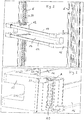
- FIG. 1 shows the door rack 10, which has two side parts 12, a front side 14 and a bottom 16, which may be embodied for example as a glass plate.
- the door rack further has a counter-profile 20, which is arranged in a profile 30 of the appliance door.
- the profile 30 is located in the channel K, which extends vertically over the entire height of the door or only over a partial area thereof.
- the side parts 12 of the door racks are constructed identically and symmetrically to the median plane of the door compartment.
- the counter-profile is rotatable about a vertical axis.
- the profile 30 has a wave structure
- the mating profile 20 has a complementary wave structure, so that both structures positively engage with each other and thus fix the door racks in the locking position in the vertical direction.
- FIG. 2 shows the door racks in the fixed on the inside of the door position.
- two channels K which are spaced apart in the lateral direction and each having two wave profiles 30. These wave profiles are located on the front and rear walls of the channels K.
- FIG. 3 illustrates that on the two side parts 12 of the door compartment 10 each a counter-profile 20 is arranged, which is a structure which is provided on two opposite sides with a wave profile.
- the contour 22 is executed part-circular and includes a counterpart on the inside of the door, which serves as a guide in the height adjustment of the door compartment.
- the reference numeral 24 denotes a lever which communicates with the counter-profile 20 in such a way that the counter-profile 20 upon actuation of the lever 24 to the vertical axis A is rotated.
- the counter-profile 20 is thus rotatably arranged on the door rack side part.
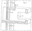
- FIG. 4 clarifies the arrangement according to FIG. 3 in a view from the receiving space of the door compartment 10 on the channel K.
- the mating profile 20 engages in the complementary profile 30 of the channel K and fixed in this way the door rack in its position.
- the mating profile 20 engages behind the front channel wall, so that the door rack is not forward, ie according to FIG. 4 can be removed to the right.
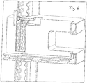
- the counter-profile 20 undergoes a rotational movement in the release position.
- the counter-profile 20 is no longer in engagement with the profile 30, so that the door rack is displaceable in the height position.
- the counter-profile 20 is thus not rotationally symmetrical with respect to its axis of rotation, but has a narrower and a wider side.
- FIG. 7 shows one FIG. 3 corresponding embodiment, wherein the counter-profile is formed here by an elastic material when the door rack is in its locking position.
- the counter-profile is formed only when the rubber or other elastic material is pressed into the profile 30.
- FIG. 8 as well as FIG. 9 show the embodiment according to FIG. 7 from the inside, ie from the receiving area of the door compartment, wherein in FIG. 9 the channel has only one wave profile 30.
- FIG. 10 a second embodiment of the door compartment can be seen.
- the mating profile consists of an inclined web which engages positively with its ends in the profile 30.
- a height adjustment of the door compartment 10 is effected by tilting the door compartment, wherein this is raised in front and the web is released with its ends from the profile 30.
- FIG. 11 shows the door racks in the second embodiment in a fixed position on the inside of the door in the normal position and FIG. 12 in the tilted position, in which the counter-profile 21 is not engaged with the profile 30.
- FIG. 13 shows a further perspective view, in which the counter-profile 21 per side part 12 of the door compartment 10 consists of two separate parts, one of which engages in the front and the other in the rear profile 30.
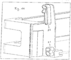
- FIG. 14 shows the arrangement according to FIG. 13 in a tilted position and makes clear that no engagement of the counter-profile 21 in the profile 30 takes place in this position.
- FIG. 15 As can be seen from this figure, located on the side part 12, a locking means 19 which is displaceable forward and backward and engages in its illustrated locking position in the profile 30, that tilting the door compartment is not possible.
- FIG. 16 shows a corresponding view without locking means.
- FIG. 17 an embodiment is apparent, the according to FIG. 15 corresponds, with the difference that the counter profiles 21 are provided with rubber inserts 22 which cooperate in the locking position with the profile 30.
- the articles 22 may also be made of a different elastic material than rubber.
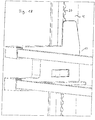
- FIG. 18 Finally, a view of the arrangement can be seen in which the channel K has only one wave profile 30.
- the height adjustment can be realized by means of a wave contour and a lock to be fixed therein according to the embodiment described above.
- the operation of the lock can vary.
- the push button 100 may be connected via a toothing with the lock 200.
- the lock 200 may be movably supported by means of pins 300 which can be latched in the storage.
- the suspension 400 which may be formed as a spiral spring, serves to restore the mechanical system in the initial state, such as Figures 20 and 21 can be seen.
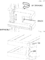
- FIG. 22 If the push button 100 remains unactuated, the stand is locked in the shaft rod and can not be moved, as is FIG. 22 evident. If the push button 100 is pressed, the toothing of the push button 100 engages in the toothing of the lock 200, as a result of which the lock 200 rotates through 90 °. The lock 200 no longer engages in the shaft rod and the stand is thus freely movable in the vertical direction, as is made FIG. 23 is removable.
- the pushbutton 100 can be seen from the front of the open door user both front (see FIGS. 19-23 ) as well as above (see Figures 24 . 25 ), be positioned below or laterally on the side part of the depositor.
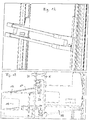
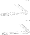
- the shaft rod is made as a separate part and adaptively placed on the knobs of the inner door, as shown in the Figures 26 and 27 emerges or the inner door is made with the wave contour in vacuum thermoforming, as in FIG. 28 is shown.
- Figures 26-28 show the door in a lying position.
- the knobs of the inner door are arranged on a vertical spar or other vertical portion of the inner door.
Landscapes
- Engineering & Computer Science (AREA)
- Chemical & Material Sciences (AREA)
- Combustion & Propulsion (AREA)
- Physics & Mathematics (AREA)
- Mechanical Engineering (AREA)
- Thermal Sciences (AREA)
- General Engineering & Computer Science (AREA)
- Refrigerator Housings (AREA)
Abstract
Description
- Die vorliegende Erfindung betrifft ein Kühl- und/oder Gefriergerät mit wenigstens einem Korpus, in dem sich zumindest ein gekühlter Innenraum befindet und mit wenigstens einer Tür, mittels derer der gekühlte Innenraum verschließbar ist, wobei an der Innenseite der Tür ein oder mehrere Türabsteller angeordnet sind.
- Aus dem Stand der Technik ist es bekannt, an der Innenseite der Tür eines Kühl- bzw. Gefriergerätes Türabsteller anzuordnen, die zur Aufnahme von Kühlgut, wie z.B. von Eiern, Butter, Getränken etc. dienen. Aus der
EP 564 952 A1 EP 2 056 049 A2 offenbart einen Türabsteller, der eine Verzahnung aufweist, die mit einer Gegenverzahnung an der Tür kämmt, wenn der Türabsteller sich in der arretierten Position befindet. Soll der Türabsteller in der Höhe verstellt werden, wird dieser gekippt, so dass die Verzahnung aus der Gegenverzahnung gelöst wird und so eine Verschiebbarkeit in Höhenrichtung möglich ist. DieEP 2 354 732 A2 offenbart einen Türabsteller, der an verschiedenen, in Höhenrichtung der Gerätetür voneinander beabstandeten Noppen arretierbar ist und der einen Abschnitt der Innenseite der Gerätetür hintergreift. - Der vorliegenden Erfindung liegt die Aufgabe zugrunde, ein Kühl- und/oder Gefriergerät der eingangs genannten Art dahingehend weiterzubilden, dass der Türabsteller zuverlässig in der Höhe verstellbar ist, ohne dass die Notwendigkeit besteht, dazu das darauf befindliche Gut zu entfernen.
- Diese Aufgabe wird durch ein Kühl- und/oder Gefriergerät mit den Merkmalen des Anspruchs 1 gelöst. Danach ist vorgesehen, dass an der Innenseite der Tür wenigstens ein sich in Höhenrichtung der Tür erstreckendes Wellenprofil angeordnet ist und dass an dem Türabsteller wenigstens ein relativ zu dem Türabsteller bewegbares oder feststehendes Gegenprofil angeordnet ist, das in einer Verriegelungsposition in das Wellenprofil eingreift und das in einer Freigabeposition nicht in das Wellenprofil eingreift, wobei das Gegenprofil derart an dem Türabsteller angeordnet ist, dass der Wechsel zwischen der Verriegelungsposition und der Freigabeposition durch eine Kipp- oder Schwenkbewegung des Gegenprofils erfolgt.
- In der Verriegelungsposition greifen Profil und Wellenprofil formschlüssig ineinander. In der Freigabeposition besteht dieser Formschluss nicht.
- Zur Veränderung der Höhenposition des Türabstellers an der Innenseite der Gerätetür wird der Türabsteller bzw. das an diesem angeordnete Gegenprofil gekippt oder verschwenkt, woraufhin der Türabsteller in Höhenrichtung der Tür verschiebbar ist.
- Bevorzugt ist es, dass ein oder mehrere Elemente des Türabstellers einen oder mehrere Elemente der Türinnenseite hintergreifen, so dass der Türabsteller aus Sicht eines Nutzers nicht nach vorne, d.h. zum Nutzer hin entfernt werden kann, vielmehr ist vorzugsweise nur eine Bewegung in Höhenrichtung möglich.
- Ein Entfernen des Gutes von dem Türabsteller im Rahmen der Höhenverstellung ist nicht erforderlich.
- Das Wellenprofil kann an oder in wenigstens einem Kanal angeordnet sein, in dem das Gegenprofil des Türabstellers geführt ist. Vorzugsweise ist der Kanal so angeordnet, dass das Gegenprofil eine Kanalwandung hintergreift, so dass der Türabsteller aus Sicht eines vor der offenen Tür stehenden Nutzers nicht zu diesem hin, sondern nur nach oben oder unten bewegt werden kann.
- Unter "Wellenprofil" ist jedes Profil zu verstehen, dass unmittelbar aufeinander folgende Erhebungen und Vertiefungen aufweist, wie beispielsweise auch eine Verzahnung. Das Wellenprofil kann sich über die gesamte Höhe des Kanals bzw. der Tür oder nur über einen Teil davon erstrecken.
- Bevorzugt ist es, wenn das Wellenprofil an zwei gegenüberliegenden Wandungen des Kanals angeordnet ist, in diesem Fall weist vorzugsweise auch der Türabsteller vorzugsweise zwei Oberflächen des Gegenprofils auf, die in die Wellenprofile eingreifen. Von der Erfindung ist auch der Fall umfasst, dass das Wellenprofil nur an einer Wandung des Kanals angeordnet ist. Die dem gegenüberliegende Wandung des Kanals kann in diesem Falle beispielsweise eben ausgeführt sein.
- Denkbar ist es, wenn das Gegenprofil in dem Kanal in Höhenrichtung der Tür bewegbar ist und nicht durch eine Bewegung nach vorne, d.h. senkrecht zur Bewegungsrichtung aus dem Kanal entnommen werden kann.
- In einer weiteren Ausgestaltung der Erfindung ist vorgesehen, dass das Gegenprofil um eine Achse drehbar ist, die in Höhenrichtung des Gerätes verläuft. Diese Achse verläuft vorzugsweise vertikal. Die Achse, um die der Türabsteller gekippt werden kann, verläuft vorzugsweise horizontal.
- In einer bevorzugten Ausgestaltung der Erfindung ist das Gegenprofil an einem Hebel angeordnet, der relativ zu dem Türabsteller bewegbar und vorzugsweise verschwenkbar ist.
- Das Gegenprofil kann fest an dem Türabsteller angeordnet sein, d.h. relativ zu dem Türabsteller nicht beweglich ausgebildet sein.
- In einer bevorzugten Ausgestaltung der Erfindung wird das Gegenprofil durch wenigstens ein elastisches Element gebildet oder weist wenigstens ein elastisches Element auf. In diesem Fall kann das Gegenprofil entweder dauerhaft vorhanden sein oder nur dann, wenn das Gegenprofil mit dem Profil zusammenwirkt, d.h. das Profil ein entsprechend komplementäres Gegenprofil erzeugt. Durch das elastische Gegenprofil ist eine stufenlose Höheneinstellung möglich, da keine vorgegebene Vorzugsposition des elastischen Profils relativ zu dem Profil der Tür besteht.
- Denkbar ist es weiterhin, dass keine Synchronisationsmittel, wie beispielsweise durch eine Stange verbundene Zahnräder vorhanden sind, die einen Gleichlauf der beiden Seiten des Türabstellers bewirken, wodurch der konstruktive Aufbau des Türabstellers entsprechend vereinfacht wird.
- Es können Arretierungsmittel vorgesehen sein, die zwischen einer Sperrstellung und einer Freigabestellung verstellbar sind, wobei die Arretierungsmittel in der Sperrstellung ein Kippen des Türabstellers verhindern. Soll der Türabsteller gekippt werden, müssen somit zunächst die Arretierungsmittel in eine Freigabestellung bewegt werden.
- Eine konstruktiv einfache Konstruktion ergibt sich, wenn keine derartigen Arretierungsmittel vorhanden sind, so dass die Höhenverstellung des Türabstellers nur nach einer Kippbewegung des Türabstellers ermöglicht wird.
- Denkbar ist es, dass die Arretierungsmittel in die Sperrstellung z.B. durch eine Feder vorgespannt sind.
- Weitere Einzelheiten und Vorteile der Erfindung werden anhand eines in der Zeichnung dargestellten Ausführungsbeispiels näher erläutert.
- Es zeigen:
- Figur 1:
- eine schematische Ansicht des Türabstellers in einer ersten Ausführungsform mit Wellenprofil und Gegenprofil,
- Figur 2:
- eine perspektivische Ansicht des Türabstellers in der an der Innenseite der Gerätetür angeordneten Position,
- Figur 3:
- eine perspektivische Ansicht auf den Türabsteller,
- Figur 4 - 6:
- perspektivische Ansichten des Türabstellerseitenteils und des Wellenprofils in der Verriegelungsposition, in einer Zwischenstellung und in der Freigabeposition,
- Figur 7:
- eine perspektivische Ansicht auf den Türabsteller in einer Ausführungsform mit Gummiaufsätzen,
- Figur 8:
- eine Ansicht des Türabstellerseitenteils in der Ausführungsform gemäß
Figur 7 in der Verriegelungsposition, - Figur 9:
- eine perspektivische Ansicht des Türabstellerseitenteils in einer Ausführung des Kanals mit nur einem Wellenprofil,
- Figur 10:
- eine schematische Ansicht des Türabstellers in einer zweiten Ausführungsform mit Wellenprofil und Gegenprofil,
- Figur 11, 12:
- eine perspektivische Ansicht des Türabstellers in der an der Innenseite der Gerätetür angeordneten normalen und gekippten Position,
- Figur 13 - 16:
- Ansichten des Türabstellers in der an der Innenseite der Gerätetür angeordneten normalen und gekippten Position sowie eine Ansicht des Türabstellerseitenteils mit und ohne Arretierungsmittel,
- Figur 17:
- eine Ansicht des Türabstellerseitenteils mit Gummiaufsätzen auf den Gegenprofilen,
- Figur 18:
- eine Ansicht des Türabstellers in einer Ausführung des Kanals mit nur einem Wellenprofil,
- Figur 19:
- eine perspektivische Ansicht des Türabstellers in der an der Innenseite der Gerätetür angeordneten Position und mit Betätigung der Verriegelung mittels Drucktaste,
- Figur 20, 21
- detaillierte Ansicht des Mechanismus der Drucktaste,
- Figur 22, 23
- detaillierte Ansicht zur Betätigung des Mechanismus der Drucktaste,
- Figur 24, 25
- alternative Anordnung der Drucktaste, und
- Figu4 26 - 28
- Darstellungen zur Fertigung der Wellenkontur.
- Die
Figuren 1 bis 9 zeigen einen Türabsteller eines Kühl- bzw. Gefriergerätes gemäß der Erfindung in einer ersten Ausführungsform und dieFiguren 10 bis 18 in einer zweiten Ausführungsform. - In den Figuren kennzeichnen gleiche Bezugszeichen gleiche oder funktionsgleiche Teile.
-
Figur 1 zeigt den Türabsteller 10, der zwei Seitenteile 12, eine Frontseite 14 und einen Boden 16 aufweist, der beispielsweise als Glasplatte ausführt sein kann. Der Türabsteller verfügt des Weiteren über ein Gegenprofil 20, das in einem Profil 30 der Gerätetür angeordnet ist. Das Profil 30 befindet sich in dem Kanal K, der sich vertikal über die gesamte Höhe der Tür oder nur über einen Teilbereich von dieser erstreckt. - Die Seitenteile 12 der Türabsteller sind identisch aufgebaut und zur Mittelebene des Türabstellers symmetrisch.
- Wie dies in
Figur 1 durch den Pfeil gekennzeichnet ist, ist das Gegenprofil um eine vertikale Achse drehbar. - Das Profil 30 weist eine Wellenstruktur auf, das Gegenprofil 20 eine dazu komplementäre Wellenstruktur, so dass beide Strukturen formschlüssig ineinander greifen und somit den Türabsteller in der Verriegelungsposition in Höhenrichtung fixieren.
-
Figur 2 zeigt den Türabsteller in der an der Türinnenseite fixierten Position. An der Türinnenseite befinden sich zwei Kanäle K, die in seitlicher Richtung voneinander beabstandet sind und die jeweils zwei Wellenprofile 30 aufweisen. Diese Wellenprofile befinden sich an der Vorder- und Rückwand der Kanäle K. -
Figur 3 verdeutlicht, dass an den beiden Seitenteilen 12 des Türabstellers 10 je ein Gegenprofil 20 angeordnet ist, bei dem es sich um eine Struktur handelt, die auf zwei gegenüberliegenden Seiten mit einem Wellenprofil versehen ist. - Die Kontur 22 ist teilkreisförmig ausgeführt und umfasst ein Gegenstück an der Innenseite der Tür, die als Führung bei der Höhenverstellung des Türabstellers dient.
- Das Bezugszeichen 24 kennzeichnet einen Hebel, der mit dem Gegenprofil 20 derart in Verbindung steht, dass das Gegenprofil 20 bei Betätigung des Hebels 24 um die vertikale Achse A verdreht wird. Mittels des Hebels 24 ist das Gegenprofil 20 somit drehbar an dem Türabstellerseitenteil angeordnet.
-
Figur 4 verdeutlicht die Anordnung gemäßFigur 3 in einer Ansicht von dem Aufnahmeraum des Türabstellers 10 aus auf den Kanal K. In der Verriegelungsposition greift das Gegenprofil 20 in das komplementäre Profil 30 des Kanals K ein und fixiert auf diese Weise den Türabsteller in seiner Position. - Das Gegenprofil 20 hintergreift die vordere Kanalwandung, so dass der Türabsteller nicht nach vorne, d.h. gemäß
Figur 4 nach rechts abgenommen werden kann. - Wird der Hebel über die Position in
Figur 5 in die Position nachFigur 6 verschwenkt, erfährt das Gegenprofil 20 eine Drehbewegung in die Freigabeposition. In dieser steht das Gegenprofil 20 nicht mehr in Eingriff mit dem Profil 30, so dass der Türabsteller in der Höhenposition verschiebbar ist. Das Gegenprofil 20 ist somit in Bezug auf seine Drehachse nicht rotationssymmetrisch ausgeführt, sondern weist eine schmalere und eine breitere Seite auf. -
Figur 7 zeigt eineFigur 3 entsprechende Ausführung, wobei das Gegenprofil hier durch ein elastisches Material ausgeformt wird, wenn sich der Türabsteller in seiner Verriegelungsstellung befindet. In diesem Fall wird das Gegenprofil erst dann ausgebildet, wenn der Gummi oder ein sonstiges elastisches Material in das Profil 30 eingedrückt wird.Figur 8 als auchFigur 9 zeigen die Ausführungsform gemäßFigur 7 von innen, d.h. von dem Aufnahmebereich des Türabstellers aus, wobei inFigur 9 der Kanal nur ein Wellenprofil 30 aufweist. - In
Figur 10 ist eine zweite Ausführungsform des Türabstellers ersichtlich. In dieser Ausführungsform weist der Türabsteller ein Gegenprofil 21 auf, das in einem Profil 30 des Kanals K aufgenommen ist. Das Gegenprofil besteht aus einem schräg stehenden Steg, der mit seinen Enden formschlüssig in das Profil 30 eingreift. - Eine Höhenverstellung des Türabstellers 10 erfolgt durch ein Verkippen des Türabstellers, wobei dieser vorne angehoben wird und der Steg mit seinen Enden aus dem Profil 30 gelöst wird.
-
Figur 11 zeigt den Türabsteller in der zweiten Ausführungsform in einer an der Innenseite der Tür fixierten Position in der Normalposition undFigur 12 in der gekippten Stellung, in der das Gegenprofil 21 nicht mit dem Profil 30 in Eingriff steht. -
Figur 13 zeigt eine weitere perspektivische Ansicht, bei der das Gegenprofil 21 pro Seitenteil 12 des Türabstellers 10 aus zwei voneinander getrennten Teilen besteht, von denen das eine in das vordere und das andere in das hintere Profil 30 eingreift. -
Figur 14 zeigt die Anordnung gemäßFigur 13 in einer gekippten Position und verdeutlicht, dass in dieser Position kein Eingriff des Gegenprofils 21 in das Profil 30 erfolgt. -
Figur 15 verdeutlicht die Einzelheiten des Türabstellers im Bereich des Seitenteils 12. Wie dies aus dieser Figur ersichtlich ist, befindet sich an dem Seitenteil 12 ein Arretierungsmittel 19, das nach vorne und hinten verschiebbar ist und das in seiner dargestellten Arretierungsposition so in das Profil 30 eingreift, dass ein Kippen des Türabstellers nicht möglich ist.Figur 16 zeigt eine entsprechende Ansicht ohne Arretierungsmittel. - Aus
Figur 17 ist eine Ausführung ersichtlich, die der gemäßFigur 15 entspricht, mit dem Unterschied, dass die Gegenprofile 21 mit Gummiaufsätzen 22 versehen sind, die in der Verriegelungsposition mit dem Profil 30 zusammenwirken. Die Aufsätze 22 können auch aus einem anderen elastischen Material als Gummi bestehen. - Sie ermöglichen aufgrund ihrer elastischen Eigenschaften ein Zusammenwirken mit dem Profil 30 an jeder beliebigen Position, so dass eine stufenlose Einstellung in Höhenrichtung möglich ist.
- Aus
Figur 18 ist schließlich eine Ansicht der Anordnung ersichtlich, bei der der Kanal K nur ein Wellenprofil 30 aufweist. - Die Höhenverstellung kann mithilfe einer Wellenkontur und einer darin zu fixierenden Verriegelung gemäß der oben beschriebenen Ausführung realisiert sein. Jedoch kann dabei die Betätigung der Verriegelung variieren.
- Über eine in
Figur 19 gezeigte Drucktaste 100 kann die 90°- Drehung der Verriegelung im Inneren des Abstellers ausgelöst werden. - Die Drucktaste 100 kann über eine Verzahnung mit der Verriegelung 200 verbunden sein. Die Verriegelung 200 kann mithilfe von Stiften 300 beweglich gelagert sein, die im Absteller verrastbar sind. Die Federung 400, die als Spiralfeder ausgebildet sein kann, dient zur Rückstellung des mechanischen Systems in den Ausgangszustand, wie den
Figuren 20 und21 zu entnehmen ist. - Bleibt die Drucktaste 100 unbetätigt, ist der Absteller in der Wellenstange verriegelt und kann nicht bewegt werden, wie dies aus
Figur 22 hervorgeht. Wird die Drucktaste 100 gedrückt, greift die Verzahnung der Drucktaste 100 in die Verzahnung der Verriegelung 200 ein, wodurch sich die Verriegelung 200 um 90° dreht. Die Verriegelung 200 greift nicht mehr in die Wellenstange ein und der Absteller ist somit in vertikale Richtung frei beweglich, wie dies ausFigur 23 entnehmbar ist. - Die Drucktaste 100 kann aus Sicht eines vor der geöffneten Tür stehenden Nutzers sowohl vorn (siehe
Figuren 19- 23 ) als auch oben (sieheFiguren 24 ,25 ), unten oder seitlich am Seitenteil des Abstellers positioniert sein. - In den
Figuren 24 und25 ist eine Variante dargestellt, bei der die Drucktaste 100 an der Oberseite des Abstellers positioniert ist. Durch das Herunterdrücken der Drucktaste 100 wird über einen Gewindegang die Verriegelung 200 um 90° gedreht. Der Absteller ist somit entriegelt und kann in der Höhe verstellt werden. Mithilfe einer Druckfeder bzw. einer Federung 400 wird nach dem Loslassen der Drucktaste 100 diese in ihre Ausgangsposition zurückgestellt. Der Absteller ist wieder verriegelt. - Bezüglich der Fertigung der Wellenkontur gibt es wenigstens zwei Möglichkeiten. Entweder wird die Wellenstange als separates Teil gefertigt und adaptiv auf die Noppen der Innentür aufgesetzt, wie dies aus den
Figuren 26 und27 hervorgeht oder die Innentür wird mit der Wellenkontur im Vakuum-Tiefziehverfahren hergestellt, wie dies inFigur 28 gezeigt ist. - Es wird darauf hingewiesen, dass die
Figuren 26-28 die Tür in einer liegenden Position zeigen. Die Noppen der Innentür sind an einem vertikalen Holm oder sonstigem vertikalen Abschnitt der Innentür angeordnet.
Claims (10)
- Kühl- und/oder Gefriergerät mit wengistens einem Korpus, in dem sich zumindest ein gekühlter Innenraum befindet und mit wengistens einer Tür, mittels derer der gekühlte Innenraum verschließbar ist, wobei an der Innenseite der Tür ein oder mehrere Türabsteller angeordnet sind, dadurch gekennzeichnet, dass an der Innenseite der Tür wenigstens ein sich in Höhenrichtung der Tür erstreckendes Wellenprofil angeordnet ist und dass an dem Türabsteller wenigstens ein relativ zu dem Türabsteller bewegbares oder feststehendes Gegenprofil angeordnet ist, das in einer Verriegelungsposition in das Wellenprofil eingreift und das in einer Freigabeposition nicht in das Wellenprofil eingreift, wobei das Gegenprofil derart an dem Türabsteller angeordnet ist, dass der Wechsel zwischen der Verriegelungsposition und der Freigabeposition durch eine Kipp- oder Schwenkbewegung des Gegenprofils erfolgt.
- Kühl- und/oder Gefriergerät nach Anspruch 1, dadurch gekennzeichnet, dass das Wellenprofil an oder in wenigstens einem Kanal angeordnet ist, in dem das Gegenprofil des Türabstellers geführt ist.
- Kühl- und/oder Gefriergerät nach Anspruch 2, dadurch gekennzeichnet, dass das Wellenprofil an zwei gegenüberliegenden Wandungen des Kanals angeordnet ist oder dass das Wellenprofil nur an einer Wandung des Kanals angeordnet ist.
- Kühl- und/oder Gefriergerät nach Anspruch 2 oder 3, dadurch gekennzeichnet, dass das Gegenprofil in dem Kanal in Höhenrichtung der Tür bewegbar ist und nicht durch eine Bewegung nach vorne aus dem Kanal entnommen werden kann.
- Kühl- und/oder Gefriergerät nach einem der vorhergehenden Ansprüche, dadurch gekennzeichnet, dass das Gegenprofil um eine Achse drehbar ist, die in Höhenrichtung des Gerätes verläuft.
- Kühl- und/oder Gefriergerät nach einem der vorhergehenden Ansprüche, dadurch gekennzeichnet, dass das Gegenprofil an einem Hebel angeordnet ist, der relativ zu dem Türabsteller bewegbar ist.
- Kühl- und/oder Gefriergerät nach einem der vorhergehenden Ansprüche, dadurch gekennzeichnet, dass das Gegenprofil fest an dem Türabsteller angeordnet ist und/oder dass das Gegenprofil durch wenigstens ein elastisches Element gebildet wird.
- Kühl- und/oder Gefriergerät nach einem der vorhergehenden Ansprüche, dadurch gekennzeichnet, dass keine Synchronisationsmittel vorhanden sind, die einen Gleichlauf der beiden Seiten des Türabstellers bewirken.
- Kühl- und/oder Gefriergerät nach einem der vorhergehenden Ansprüche, dadurch gekennzeichnet, dass Arretierungsmittel vorgesehen sind, die zwischen einer Sperrstellung und einer Freigabestellung verstellbar sind, wobei die Arretierungsmittel in der Sperrstellung ein Kippen des Türabstellers verhindern oder dass keine derartigen Arretierungsmittel vorhanden sind, so dass die Höhenverstellung des Türabstellers nur durch eine Kippbewegung des Türabstellers ermöglicht wird.
- Kühl- und/oder Gefriergerät nach Anspruch 9, dadurch gekennzeichnet, dass die Arretierungsmittel in die Sperrstellung vorgespannt sind.
Applications Claiming Priority (1)
| Application Number | Priority Date | Filing Date | Title |
|---|---|---|---|
| DE102016002857 | 2016-03-09 |
Publications (2)
| Publication Number | Publication Date |
|---|---|
| EP3217129A1 true EP3217129A1 (de) | 2017-09-13 |
| EP3217129B1 EP3217129B1 (de) | 2021-02-17 |
Family
ID=58265836
Family Applications (1)
| Application Number | Title | Priority Date | Filing Date |
|---|---|---|---|
| EP17159866.7A Active EP3217129B1 (de) | 2016-03-09 | 2017-03-08 | Kühl- und/oder gefriergerät |
Country Status (2)
| Country | Link |
|---|---|
| EP (1) | EP3217129B1 (de) |
| DE (1) | DE102017002245A1 (de) |
Cited By (1)
| Publication number | Priority date | Publication date | Assignee | Title |
|---|---|---|---|---|
| JP2022102143A (ja) * | 2020-12-25 | 2022-07-07 | アクア株式会社 | 冷蔵庫 |
Citations (8)
| Publication number | Priority date | Publication date | Assignee | Title |
|---|---|---|---|---|
| EP0564952A1 (de) | 1992-04-06 | 1993-10-13 | LIEBHERR-HAUSGERÄTE GmbH | Kühlschranktür |
| KR20040065368A (ko) * | 2003-01-14 | 2004-07-22 | 삼성전자주식회사 | 냉장고용 선반, 냉장고용 선반 고정 장치 및 냉장고 |
| EP2056049A2 (de) | 2007-05-09 | 2009-05-06 | Liebherr-Hausgeräte Ochsenhausen GmbH | Vorrichtung zur Verstellung eines Bodens oder Abstellers eines Kühl- und/oder Gefriergerätes |
| EP2104820A2 (de) * | 2006-12-22 | 2009-09-30 | BSH Bosch und Siemens Hausgeräte GmbH | Kältegerät |
| EP2354732A2 (de) | 2010-01-28 | 2011-08-10 | Liebherr-Hausgeräte Ochsenhausen GmbH | Tür eines Kühl- und/oder Gefriergerätes |
| EP2664878A2 (de) * | 2012-05-15 | 2013-11-20 | Gorenje d.d. | System zur vertikalen Anpassung eines Abstellbehälters in einer Tür eines Haushaltsgeräts |
| DE102013206403A1 (de) * | 2013-04-11 | 2014-10-16 | BSH Bosch und Siemens Hausgeräte GmbH | Kältegerät mit einem Türabsteller |
| EP3032198A1 (de) * | 2014-12-08 | 2016-06-15 | BSH Hausgeräte GmbH | Tür mit einer höhenverstellvorrichtung für einen türabsteller, haushaltskältegerät mit einer derartigen tür und verfahren zum verstellen eines türabstellers |
-
2017
- 2017-03-08 EP EP17159866.7A patent/EP3217129B1/de active Active
- 2017-03-08 DE DE102017002245.3A patent/DE102017002245A1/de not_active Withdrawn
Patent Citations (9)
| Publication number | Priority date | Publication date | Assignee | Title |
|---|---|---|---|---|
| EP0564952A1 (de) | 1992-04-06 | 1993-10-13 | LIEBHERR-HAUSGERÄTE GmbH | Kühlschranktür |
| KR20040065368A (ko) * | 2003-01-14 | 2004-07-22 | 삼성전자주식회사 | 냉장고용 선반, 냉장고용 선반 고정 장치 및 냉장고 |
| EP2104820A2 (de) * | 2006-12-22 | 2009-09-30 | BSH Bosch und Siemens Hausgeräte GmbH | Kältegerät |
| EP2056049A2 (de) | 2007-05-09 | 2009-05-06 | Liebherr-Hausgeräte Ochsenhausen GmbH | Vorrichtung zur Verstellung eines Bodens oder Abstellers eines Kühl- und/oder Gefriergerätes |
| EP2354732A2 (de) | 2010-01-28 | 2011-08-10 | Liebherr-Hausgeräte Ochsenhausen GmbH | Tür eines Kühl- und/oder Gefriergerätes |
| DE102010022203A1 (de) * | 2010-01-28 | 2011-08-18 | Liebherr-Hausgeräte Ochsenhausen GmbH, 88416 | Tür eines Kühl- und/oder Gefriergerätes |
| EP2664878A2 (de) * | 2012-05-15 | 2013-11-20 | Gorenje d.d. | System zur vertikalen Anpassung eines Abstellbehälters in einer Tür eines Haushaltsgeräts |
| DE102013206403A1 (de) * | 2013-04-11 | 2014-10-16 | BSH Bosch und Siemens Hausgeräte GmbH | Kältegerät mit einem Türabsteller |
| EP3032198A1 (de) * | 2014-12-08 | 2016-06-15 | BSH Hausgeräte GmbH | Tür mit einer höhenverstellvorrichtung für einen türabsteller, haushaltskältegerät mit einer derartigen tür und verfahren zum verstellen eines türabstellers |
Cited By (2)
| Publication number | Priority date | Publication date | Assignee | Title |
|---|---|---|---|---|
| JP2022102143A (ja) * | 2020-12-25 | 2022-07-07 | アクア株式会社 | 冷蔵庫 |
| CN116670452A (zh) * | 2020-12-25 | 2023-08-29 | 海尔智家股份有限公司 | 冰箱 |
Also Published As
| Publication number | Publication date |
|---|---|
| EP3217129B1 (de) | 2021-02-17 |
| DE102017002245A1 (de) | 2017-09-14 |
Similar Documents
| Publication | Publication Date | Title |
|---|---|---|
| EP2770876B1 (de) | Synchronisierte verriegelung für ein bewegbares möbelteil | |
| WO2009115133A1 (de) | Kältegerät und zugehörige einteilige rastmittelanordnung | |
| DE202007013356U1 (de) | Vorrichtung zur Verstellung eines Bodens oder Abstellers eines Kühl- und/oder Gefriergerätes | |
| EP2499445B1 (de) | Kältegerät mit einem türabsteller und einer schwimmend gelagerten rastvorrichtung | |
| DE102013015463B4 (de) | Kühl- und/oder Gefriergerät | |
| EP2250929A1 (de) | Schrankteil mit herausziehbarem Ausziehteil | |
| WO2012130578A1 (de) | Tür und türabsteller für ein kältegerät | |
| DE102008018231A1 (de) | Kältegerät insbesondere Haushalts- Kältegerät, mit einem Türabsteller | |
| EP4385363A2 (de) | Anordnung mit antriebsvorrichtung und synchronisierungsvorrichtung für ausziehführungen für eine schublade | |
| EP2056049A2 (de) | Vorrichtung zur Verstellung eines Bodens oder Abstellers eines Kühl- und/oder Gefriergerätes | |
| EP3487359B1 (de) | Ausstossvorrichtung für ein bewegbares möbelteil und möbel | |
| EP3217129B1 (de) | Kühl- und/oder gefriergerät | |
| DE102017001178A1 (de) | Kühl- und/oder Gefriergerät | |
| AT503010B1 (de) | Ausziehführung für ein aus einem möbelkorpus ausziehbares möbelteil | |
| EP2513578B1 (de) | Kältegerät mit einem türabsteller und einer kulissenführung | |
| DE102015211295A1 (de) | Vorrichtung zum Sichern von Ladegut in einem Laderaum eines Kraftfahrzeugs | |
| EP2851493B1 (de) | Türgriffanordnung für ein Kraftfahrzeug | |
| DE102012001374A1 (de) | Kühl- und/oder Gefriergerät | |
| EP3745916B1 (de) | Anordnung aus ausziehführung, schienen-synchronisierungsvorrichtung und mitnehmer | |
| DE19547455B4 (de) | Schubladenartig ausgebildetes Ablagefach | |
| EP2265875B1 (de) | Kältegerät und zugehörige einteilige rastmittelanordnung | |
| DE1903282C3 (de) | Schubladenschrank | |
| EP3745061B1 (de) | Kühl- und/oder gefriergerät | |
| DE202013004939U1 (de) | Vorrichtung zur Positionierung und Fixierung eines beweglichen Möbelteils | |
| EP1561891A2 (de) | Schwenkmechanismus zum Öffnen und Schliessen einer aus einem Türblatt und einem Türrahmen bestehenden Tür, insbesondere einer Fahrzeugtür |
Legal Events
| Date | Code | Title | Description |
|---|---|---|---|
| PUAI | Public reference made under article 153(3) epc to a published international application that has entered the european phase |
Free format text: ORIGINAL CODE: 0009012 |
|
| STAA | Information on the status of an ep patent application or granted ep patent |
Free format text: STATUS: THE APPLICATION HAS BEEN PUBLISHED |
|
| AK | Designated contracting states |
Kind code of ref document: A1 Designated state(s): AL AT BE BG CH CY CZ DE DK EE ES FI FR GB GR HR HU IE IS IT LI LT LU LV MC MK MT NL NO PL PT RO RS SE SI SK SM TR |
|
| AX | Request for extension of the european patent |
Extension state: BA ME |
|
| STAA | Information on the status of an ep patent application or granted ep patent |
Free format text: STATUS: REQUEST FOR EXAMINATION WAS MADE |
|
| 17P | Request for examination filed |
Effective date: 20180313 |
|
| STAA | Information on the status of an ep patent application or granted ep patent |
Free format text: STATUS: EXAMINATION IS IN PROGRESS |
|
| 17Q | First examination report despatched |
Effective date: 20190425 |
|
| GRAP | Despatch of communication of intention to grant a patent |
Free format text: ORIGINAL CODE: EPIDOSNIGR1 |
|
| STAA | Information on the status of an ep patent application or granted ep patent |
Free format text: STATUS: GRANT OF PATENT IS INTENDED |
|
| INTG | Intention to grant announced |
Effective date: 20200819 |
|
| GRAS | Grant fee paid |
Free format text: ORIGINAL CODE: EPIDOSNIGR3 |
|
| GRAA | (expected) grant |
Free format text: ORIGINAL CODE: 0009210 |
|
| STAA | Information on the status of an ep patent application or granted ep patent |
Free format text: STATUS: THE PATENT HAS BEEN GRANTED |
|
| AK | Designated contracting states |
Kind code of ref document: B1 Designated state(s): AL AT BE BG CH CY CZ DE DK EE ES FI FR GB GR HR HU IE IS IT LI LT LU LV MC MK MT NL NO PL PT RO RS SE SI SK SM TR |
|
| REG | Reference to a national code |
Ref country code: GB Ref legal event code: FG4D Free format text: NOT ENGLISH |
|
| REG | Reference to a national code |
Ref country code: CH Ref legal event code: EP |
|
| REG | Reference to a national code |
Ref country code: DE Ref legal event code: R096 Ref document number: 502017009305 Country of ref document: DE |
|
| REG | Reference to a national code |
Ref country code: AT Ref legal event code: REF Ref document number: 1362005 Country of ref document: AT Kind code of ref document: T Effective date: 20210315 |
|
| REG | Reference to a national code |
Ref country code: IE Ref legal event code: FG4D Free format text: LANGUAGE OF EP DOCUMENT: GERMAN |
|
| REG | Reference to a national code |
Ref country code: LT Ref legal event code: MG9D |
|
| REG | Reference to a national code |
Ref country code: NL Ref legal event code: MP Effective date: 20210217 |
|
| PG25 | Lapsed in a contracting state [announced via postgrant information from national office to epo] |
Ref country code: NO Free format text: LAPSE BECAUSE OF FAILURE TO SUBMIT A TRANSLATION OF THE DESCRIPTION OR TO PAY THE FEE WITHIN THE PRESCRIBED TIME-LIMIT Effective date: 20210517 Ref country code: PT Free format text: LAPSE BECAUSE OF FAILURE TO SUBMIT A TRANSLATION OF THE DESCRIPTION OR TO PAY THE FEE WITHIN THE PRESCRIBED TIME-LIMIT Effective date: 20210617 Ref country code: FI Free format text: LAPSE BECAUSE OF FAILURE TO SUBMIT A TRANSLATION OF THE DESCRIPTION OR TO PAY THE FEE WITHIN THE PRESCRIBED TIME-LIMIT Effective date: 20210217 Ref country code: GR Free format text: LAPSE BECAUSE OF FAILURE TO SUBMIT A TRANSLATION OF THE DESCRIPTION OR TO PAY THE FEE WITHIN THE PRESCRIBED TIME-LIMIT Effective date: 20210518 Ref country code: HR Free format text: LAPSE BECAUSE OF FAILURE TO SUBMIT A TRANSLATION OF THE DESCRIPTION OR TO PAY THE FEE WITHIN THE PRESCRIBED TIME-LIMIT Effective date: 20210217 Ref country code: LT Free format text: LAPSE BECAUSE OF FAILURE TO SUBMIT A TRANSLATION OF THE DESCRIPTION OR TO PAY THE FEE WITHIN THE PRESCRIBED TIME-LIMIT Effective date: 20210217 Ref country code: BG Free format text: LAPSE BECAUSE OF FAILURE TO SUBMIT A TRANSLATION OF THE DESCRIPTION OR TO PAY THE FEE WITHIN THE PRESCRIBED TIME-LIMIT Effective date: 20210517 |
|
| PG25 | Lapsed in a contracting state [announced via postgrant information from national office to epo] |
Ref country code: RS Free format text: LAPSE BECAUSE OF FAILURE TO SUBMIT A TRANSLATION OF THE DESCRIPTION OR TO PAY THE FEE WITHIN THE PRESCRIBED TIME-LIMIT Effective date: 20210217 Ref country code: LV Free format text: LAPSE BECAUSE OF FAILURE TO SUBMIT A TRANSLATION OF THE DESCRIPTION OR TO PAY THE FEE WITHIN THE PRESCRIBED TIME-LIMIT Effective date: 20210217 Ref country code: NL Free format text: LAPSE BECAUSE OF FAILURE TO SUBMIT A TRANSLATION OF THE DESCRIPTION OR TO PAY THE FEE WITHIN THE PRESCRIBED TIME-LIMIT Effective date: 20210217 Ref country code: PL Free format text: LAPSE BECAUSE OF FAILURE TO SUBMIT A TRANSLATION OF THE DESCRIPTION OR TO PAY THE FEE WITHIN THE PRESCRIBED TIME-LIMIT Effective date: 20210217 Ref country code: SE Free format text: LAPSE BECAUSE OF FAILURE TO SUBMIT A TRANSLATION OF THE DESCRIPTION OR TO PAY THE FEE WITHIN THE PRESCRIBED TIME-LIMIT Effective date: 20210217 |
|
| PG25 | Lapsed in a contracting state [announced via postgrant information from national office to epo] |
Ref country code: IS Free format text: LAPSE BECAUSE OF FAILURE TO SUBMIT A TRANSLATION OF THE DESCRIPTION OR TO PAY THE FEE WITHIN THE PRESCRIBED TIME-LIMIT Effective date: 20210617 |
|
| PG25 | Lapsed in a contracting state [announced via postgrant information from national office to epo] |
Ref country code: SM Free format text: LAPSE BECAUSE OF FAILURE TO SUBMIT A TRANSLATION OF THE DESCRIPTION OR TO PAY THE FEE WITHIN THE PRESCRIBED TIME-LIMIT Effective date: 20210217 Ref country code: EE Free format text: LAPSE BECAUSE OF FAILURE TO SUBMIT A TRANSLATION OF THE DESCRIPTION OR TO PAY THE FEE WITHIN THE PRESCRIBED TIME-LIMIT Effective date: 20210217 Ref country code: CZ Free format text: LAPSE BECAUSE OF FAILURE TO SUBMIT A TRANSLATION OF THE DESCRIPTION OR TO PAY THE FEE WITHIN THE PRESCRIBED TIME-LIMIT Effective date: 20210217 |
|
| REG | Reference to a national code |
Ref country code: CH Ref legal event code: PL |
|
| REG | Reference to a national code |
Ref country code: DE Ref legal event code: R097 Ref document number: 502017009305 Country of ref document: DE |
|
| PG25 | Lapsed in a contracting state [announced via postgrant information from national office to epo] |
Ref country code: RO Free format text: LAPSE BECAUSE OF FAILURE TO SUBMIT A TRANSLATION OF THE DESCRIPTION OR TO PAY THE FEE WITHIN THE PRESCRIBED TIME-LIMIT Effective date: 20210217 Ref country code: SK Free format text: LAPSE BECAUSE OF FAILURE TO SUBMIT A TRANSLATION OF THE DESCRIPTION OR TO PAY THE FEE WITHIN THE PRESCRIBED TIME-LIMIT Effective date: 20210217 Ref country code: MC Free format text: LAPSE BECAUSE OF FAILURE TO SUBMIT A TRANSLATION OF THE DESCRIPTION OR TO PAY THE FEE WITHIN THE PRESCRIBED TIME-LIMIT Effective date: 20210217 Ref country code: DK Free format text: LAPSE BECAUSE OF FAILURE TO SUBMIT A TRANSLATION OF THE DESCRIPTION OR TO PAY THE FEE WITHIN THE PRESCRIBED TIME-LIMIT Effective date: 20210217 |
|
| REG | Reference to a national code |
Ref country code: BE Ref legal event code: MM Effective date: 20210331 |
|
| PLBE | No opposition filed within time limit |
Free format text: ORIGINAL CODE: 0009261 |
|
| STAA | Information on the status of an ep patent application or granted ep patent |
Free format text: STATUS: NO OPPOSITION FILED WITHIN TIME LIMIT |
|
| 26N | No opposition filed |
Effective date: 20211118 |
|
| GBPC | Gb: european patent ceased through non-payment of renewal fee |
Effective date: 20210517 |
|
| PG25 | Lapsed in a contracting state [announced via postgrant information from national office to epo] |
Ref country code: IE Free format text: LAPSE BECAUSE OF NON-PAYMENT OF DUE FEES Effective date: 20210308 Ref country code: FR Free format text: LAPSE BECAUSE OF NON-PAYMENT OF DUE FEES Effective date: 20210417 Ref country code: ES Free format text: LAPSE BECAUSE OF FAILURE TO SUBMIT A TRANSLATION OF THE DESCRIPTION OR TO PAY THE FEE WITHIN THE PRESCRIBED TIME-LIMIT Effective date: 20210217 Ref country code: AL Free format text: LAPSE BECAUSE OF FAILURE TO SUBMIT A TRANSLATION OF THE DESCRIPTION OR TO PAY THE FEE WITHIN THE PRESCRIBED TIME-LIMIT Effective date: 20210217 Ref country code: CH Free format text: LAPSE BECAUSE OF NON-PAYMENT OF DUE FEES Effective date: 20210331 Ref country code: LI Free format text: LAPSE BECAUSE OF NON-PAYMENT OF DUE FEES Effective date: 20210331 Ref country code: LU Free format text: LAPSE BECAUSE OF NON-PAYMENT OF DUE FEES Effective date: 20210308 |
|
| PG25 | Lapsed in a contracting state [announced via postgrant information from national office to epo] |
Ref country code: SI Free format text: LAPSE BECAUSE OF FAILURE TO SUBMIT A TRANSLATION OF THE DESCRIPTION OR TO PAY THE FEE WITHIN THE PRESCRIBED TIME-LIMIT Effective date: 20210217 |
|
| PG25 | Lapsed in a contracting state [announced via postgrant information from national office to epo] |
Ref country code: IT Free format text: LAPSE BECAUSE OF FAILURE TO SUBMIT A TRANSLATION OF THE DESCRIPTION OR TO PAY THE FEE WITHIN THE PRESCRIBED TIME-LIMIT Effective date: 20210217 Ref country code: GB Free format text: LAPSE BECAUSE OF NON-PAYMENT OF DUE FEES Effective date: 20210517 |
|
| PG25 | Lapsed in a contracting state [announced via postgrant information from national office to epo] |
Ref country code: IS Free format text: LAPSE BECAUSE OF FAILURE TO SUBMIT A TRANSLATION OF THE DESCRIPTION OR TO PAY THE FEE WITHIN THE PRESCRIBED TIME-LIMIT Effective date: 20210617 |
|
| PG25 | Lapsed in a contracting state [announced via postgrant information from national office to epo] |
Ref country code: BE Free format text: LAPSE BECAUSE OF NON-PAYMENT OF DUE FEES Effective date: 20210331 |
|
| REG | Reference to a national code |
Ref country code: AT Ref legal event code: MM01 Ref document number: 1362005 Country of ref document: AT Kind code of ref document: T Effective date: 20220308 |
|
| PG25 | Lapsed in a contracting state [announced via postgrant information from national office to epo] |
Ref country code: HU Free format text: LAPSE BECAUSE OF FAILURE TO SUBMIT A TRANSLATION OF THE DESCRIPTION OR TO PAY THE FEE WITHIN THE PRESCRIBED TIME-LIMIT; INVALID AB INITIO Effective date: 20170308 |
|
| PG25 | Lapsed in a contracting state [announced via postgrant information from national office to epo] |
Ref country code: CY Free format text: LAPSE BECAUSE OF FAILURE TO SUBMIT A TRANSLATION OF THE DESCRIPTION OR TO PAY THE FEE WITHIN THE PRESCRIBED TIME-LIMIT Effective date: 20210217 |
|
| PG25 | Lapsed in a contracting state [announced via postgrant information from national office to epo] |
Ref country code: AT Free format text: LAPSE BECAUSE OF NON-PAYMENT OF DUE FEES Effective date: 20220308 |
|
| PG25 | Lapsed in a contracting state [announced via postgrant information from national office to epo] |
Ref country code: MK Free format text: LAPSE BECAUSE OF FAILURE TO SUBMIT A TRANSLATION OF THE DESCRIPTION OR TO PAY THE FEE WITHIN THE PRESCRIBED TIME-LIMIT Effective date: 20210217 |
|
| PG25 | Lapsed in a contracting state [announced via postgrant information from national office to epo] |
Ref country code: TR Free format text: LAPSE BECAUSE OF FAILURE TO SUBMIT A TRANSLATION OF THE DESCRIPTION OR TO PAY THE FEE WITHIN THE PRESCRIBED TIME-LIMIT Effective date: 20210217 |
|
| PG25 | Lapsed in a contracting state [announced via postgrant information from national office to epo] |
Ref country code: MT Free format text: LAPSE BECAUSE OF FAILURE TO SUBMIT A TRANSLATION OF THE DESCRIPTION OR TO PAY THE FEE WITHIN THE PRESCRIBED TIME-LIMIT Effective date: 20210217 |
|
| PGFP | Annual fee paid to national office [announced via postgrant information from national office to epo] |
Ref country code: DE Payment date: 20250331 Year of fee payment: 9 |