EP3216880A1 - Composite molten iron manufacturing apparatus - Google Patents
Composite molten iron manufacturing apparatus Download PDFInfo
- Publication number
- EP3216880A1 EP3216880A1 EP15856552.3A EP15856552A EP3216880A1 EP 3216880 A1 EP3216880 A1 EP 3216880A1 EP 15856552 A EP15856552 A EP 15856552A EP 3216880 A1 EP3216880 A1 EP 3216880A1
- Authority
- EP
- European Patent Office
- Prior art keywords
- molten iron
- manufacturing apparatus
- reduction furnace
- fine
- iron manufacturing
- Prior art date
- Legal status (The legal status is an assumption and is not a legal conclusion. Google has not performed a legal analysis and makes no representation as to the accuracy of the status listed.)
- Granted
Links
- XEEYBQQBJWHFJM-UHFFFAOYSA-N Iron Chemical compound [Fe] XEEYBQQBJWHFJM-UHFFFAOYSA-N 0.000 title claims abstract description 861
- 229910052742 iron Inorganic materials 0.000 title claims abstract description 424
- 238000004519 manufacturing process Methods 0.000 title claims abstract description 301
- 239000002131 composite material Substances 0.000 title 1
- 230000009467 reduction Effects 0.000 claims abstract description 295
- 238000002844 melting Methods 0.000 claims abstract description 88
- 230000008018 melting Effects 0.000 claims abstract description 88
- 239000003245 coal Substances 0.000 claims abstract description 82
- 239000002994 raw material Substances 0.000 claims abstract description 37
- 239000000446 fuel Substances 0.000 claims abstract description 20
- 239000007789 gas Substances 0.000 claims description 320
- 239000003638 chemical reducing agent Substances 0.000 claims description 113
- 239000000428 dust Substances 0.000 claims description 98
- QVGXLLKOCUKJST-UHFFFAOYSA-N atomic oxygen Chemical compound [O] QVGXLLKOCUKJST-UHFFFAOYSA-N 0.000 claims description 42
- 229910052760 oxygen Inorganic materials 0.000 claims description 42
- 239000001301 oxygen Substances 0.000 claims description 42
- 239000002893 slag Substances 0.000 claims description 39
- 238000001816 cooling Methods 0.000 claims description 33
- 239000006227 byproduct Substances 0.000 claims description 28
- 238000003860 storage Methods 0.000 claims description 27
- 238000002485 combustion reaction Methods 0.000 claims description 24
- 238000002156 mixing Methods 0.000 claims description 24
- 239000000463 material Substances 0.000 claims description 20
- 238000011084 recovery Methods 0.000 claims description 20
- 238000006243 chemical reaction Methods 0.000 claims description 19
- 238000010438 heat treatment Methods 0.000 claims description 17
- 238000004140 cleaning Methods 0.000 claims description 9
- 238000004090 dissolution Methods 0.000 claims description 7
- 239000002737 fuel gas Substances 0.000 claims description 7
- 230000001590 oxidative effect Effects 0.000 claims description 7
- 230000008859 change Effects 0.000 claims description 6
- 238000007599 discharging Methods 0.000 claims description 6
- 239000000155 melt Substances 0.000 claims description 6
- 239000007800 oxidant agent Substances 0.000 claims description 6
- 239000000284 extract Substances 0.000 claims description 3
- 238000005272 metallurgy Methods 0.000 abstract description 4
- 238000006722 reduction reaction Methods 0.000 description 235
- 238000000034 method Methods 0.000 description 30
- 239000000203 mixture Substances 0.000 description 23
- VYPSYNLAJGMNEJ-UHFFFAOYSA-N Silicium dioxide Chemical compound O=[Si]=O VYPSYNLAJGMNEJ-UHFFFAOYSA-N 0.000 description 16
- 230000008569 process Effects 0.000 description 14
- PNEYBMLMFCGWSK-UHFFFAOYSA-N aluminium oxide Inorganic materials [O-2].[O-2].[O-2].[Al+3].[Al+3] PNEYBMLMFCGWSK-UHFFFAOYSA-N 0.000 description 8
- 229910052681 coesite Inorganic materials 0.000 description 8
- 229910052593 corundum Inorganic materials 0.000 description 8
- 229910052906 cristobalite Inorganic materials 0.000 description 8
- 239000000377 silicon dioxide Substances 0.000 description 8
- 235000012239 silicon dioxide Nutrition 0.000 description 8
- 229910052682 stishovite Inorganic materials 0.000 description 8
- 229910052905 tridymite Inorganic materials 0.000 description 8
- 229910001845 yogo sapphire Inorganic materials 0.000 description 8
- UQSXHKLRYXJYBZ-UHFFFAOYSA-N iron oxide Inorganic materials [Fe]=O UQSXHKLRYXJYBZ-UHFFFAOYSA-N 0.000 description 6
- 238000009628 steelmaking Methods 0.000 description 6
- 238000004939 coking Methods 0.000 description 5
- 238000009826 distribution Methods 0.000 description 5
- 230000000694 effects Effects 0.000 description 5
- GWEVSGVZZGPLCZ-UHFFFAOYSA-N Titan oxide Chemical compound O=[Ti]=O GWEVSGVZZGPLCZ-UHFFFAOYSA-N 0.000 description 4
- BYFGZMCJNACEKR-UHFFFAOYSA-N aluminium(i) oxide Chemical compound [Al]O[Al] BYFGZMCJNACEKR-UHFFFAOYSA-N 0.000 description 4
- 239000000567 combustion gas Substances 0.000 description 4
- 238000010586 diagram Methods 0.000 description 4
- SZVJSHCCFOBDDC-UHFFFAOYSA-N iron(II,III) oxide Inorganic materials O=[Fe]O[Fe]O[Fe]=O SZVJSHCCFOBDDC-UHFFFAOYSA-N 0.000 description 4
- 239000000571 coke Substances 0.000 description 3
- 239000011148 porous material Substances 0.000 description 3
- OKTJSMMVPCPJKN-UHFFFAOYSA-N Carbon Chemical compound [C] OKTJSMMVPCPJKN-UHFFFAOYSA-N 0.000 description 2
- 229910004742 Na2 O Inorganic materials 0.000 description 2
- KKCBUQHMOMHUOY-UHFFFAOYSA-N Na2O Inorganic materials [O-2].[Na+].[Na+] KKCBUQHMOMHUOY-UHFFFAOYSA-N 0.000 description 2
- 229910004298 SiO 2 Inorganic materials 0.000 description 2
- 229910010413 TiO 2 Inorganic materials 0.000 description 2
- RHZUVFJBSILHOK-UHFFFAOYSA-N anthracen-1-ylmethanolate Chemical compound C1=CC=C2C=C3C(C[O-])=CC=CC3=CC2=C1 RHZUVFJBSILHOK-UHFFFAOYSA-N 0.000 description 2
- 239000003830 anthracite Substances 0.000 description 2
- 229910052799 carbon Inorganic materials 0.000 description 2
- BHEPBYXIRTUNPN-UHFFFAOYSA-N hydridophosphorus(.) (triplet) Chemical compound [PH] BHEPBYXIRTUNPN-UHFFFAOYSA-N 0.000 description 2
- 239000012535 impurity Substances 0.000 description 2
- 238000002347 injection Methods 0.000 description 2
- 239000007924 injection Substances 0.000 description 2
- 239000002245 particle Substances 0.000 description 2
- 229910052698 phosphorus Inorganic materials 0.000 description 2
- 238000007670 refining Methods 0.000 description 2
- 238000005245 sintering Methods 0.000 description 2
- 229910052717 sulfur Inorganic materials 0.000 description 2
- 239000004484 Briquette Substances 0.000 description 1
- 229910018663 Mn O Inorganic materials 0.000 description 1
- 229910000831 Steel Inorganic materials 0.000 description 1
- 239000002802 bituminous coal Substances 0.000 description 1
- 230000003247 decreasing effect Effects 0.000 description 1
- 238000010410 dusting Methods 0.000 description 1
- 239000003344 environmental pollutant Substances 0.000 description 1
- 238000003912 environmental pollution Methods 0.000 description 1
- 238000010304 firing Methods 0.000 description 1
- 229910052739 hydrogen Inorganic materials 0.000 description 1
- 230000006872 improvement Effects 0.000 description 1
- 238000009434 installation Methods 0.000 description 1
- 239000002184 metal Substances 0.000 description 1
- 229910052751 metal Inorganic materials 0.000 description 1
- 238000012986 modification Methods 0.000 description 1
- 230000004048 modification Effects 0.000 description 1
- 230000002265 prevention Effects 0.000 description 1
- 239000011819 refractory material Substances 0.000 description 1
- 239000000243 solution Substances 0.000 description 1
- 239000010959 steel Substances 0.000 description 1
- 238000009423 ventilation Methods 0.000 description 1
Images



Classifications
-
- C—CHEMISTRY; METALLURGY
- C21—METALLURGY OF IRON
- C21B—MANUFACTURE OF IRON OR STEEL
- C21B13/00—Making spongy iron or liquid steel, by direct processes
- C21B13/14—Multi-stage processes processes carried out in different vessels or furnaces
-
- C—CHEMISTRY; METALLURGY
- C21—METALLURGY OF IRON
- C21B—MANUFACTURE OF IRON OR STEEL
- C21B13/00—Making spongy iron or liquid steel, by direct processes
- C21B13/0006—Making spongy iron or liquid steel, by direct processes obtaining iron or steel in a molten state
-
- C—CHEMISTRY; METALLURGY
- C21—METALLURGY OF IRON
- C21B—MANUFACTURE OF IRON OR STEEL
- C21B13/00—Making spongy iron or liquid steel, by direct processes
- C21B13/0033—In fluidised bed furnaces or apparatus containing a dispersion of the material
-
- C—CHEMISTRY; METALLURGY
- C21—METALLURGY OF IRON
- C21B—MANUFACTURE OF IRON OR STEEL
- C21B13/00—Making spongy iron or liquid steel, by direct processes
- C21B13/0073—Selection or treatment of the reducing gases
-
- C—CHEMISTRY; METALLURGY
- C21—METALLURGY OF IRON
- C21B—MANUFACTURE OF IRON OR STEEL
- C21B2100/00—Handling of exhaust gases produced during the manufacture of iron or steel
- C21B2100/20—Increasing the gas reduction potential of recycled exhaust gases
- C21B2100/26—Increasing the gas reduction potential of recycled exhaust gases by adding additional fuel in recirculation pipes
-
- C—CHEMISTRY; METALLURGY
- C21—METALLURGY OF IRON
- C21B—MANUFACTURE OF IRON OR STEEL
- C21B2100/00—Handling of exhaust gases produced during the manufacture of iron or steel
- C21B2100/20—Increasing the gas reduction potential of recycled exhaust gases
- C21B2100/28—Increasing the gas reduction potential of recycled exhaust gases by separation
- C21B2100/282—Increasing the gas reduction potential of recycled exhaust gases by separation of carbon dioxide
-
- C—CHEMISTRY; METALLURGY
- C21—METALLURGY OF IRON
- C21B—MANUFACTURE OF IRON OR STEEL
- C21B2100/00—Handling of exhaust gases produced during the manufacture of iron or steel
- C21B2100/40—Gas purification of exhaust gases to be recirculated or used in other metallurgical processes
- C21B2100/44—Removing particles, e.g. by scrubbing, dedusting
-
- C—CHEMISTRY; METALLURGY
- C21—METALLURGY OF IRON
- C21B—MANUFACTURE OF IRON OR STEEL
- C21B2100/00—Handling of exhaust gases produced during the manufacture of iron or steel
- C21B2100/60—Process control or energy utilisation in the manufacture of iron or steel
- C21B2100/66—Heat exchange
Definitions
- the present invention relates to a combined molten iron manufacturing apparatus, and more particularly, to a combined molten iron manufacturing apparatus configured by combining reactors that perform reduction, dissolution, and the like of a plurality of iron-containing materials having various forms and functions so as to directly use fuel and raw materials with various ranks and particle sizes when manufacturing molten iron by directly using fine or compacted general coals or fine iron-containing ores.
- the blast furnace method is a method for manufacturing molten iron in which coke and the like manufactured by using iron ores and bituminous coal as raw materials which are subject to a sintering process are added in a blast furnace, and oxygen is supplied to the furnace to reduce the iron ore to iron.
- the blast furnace method which forms its majority of a molten iron producing apparatus requires a raw materials that has a strength of a predetermined level or more due to the reaction characteristic and has a particle diameter capable of ensuring ventilation in the furnace, as described above, a carbon source used as fuel and a reductant depends on the coke processed by specific coking coal and an iron source depends on sintered ore that is subjected to a series of compacting processes.
- an apparatus fro manufacturing molten iron directly using fine or lump coals and fine iron-containing ores is configured by a multi-stage fluidized reduction furnace that reduces and fires fine iron-containing ores and supplementary raw materials by contacting hot reducing gas; a hot compacting device that compacts the fine reduced iron discharged from the fluidized reduction furnace to manufacture hot reduced compacted iron; and a melter-gasifier in which briquette coals compacted and manufactured from fine general coals and compacted general coals are continuously supplied to form a coal filling layer with a predetermined height therein, oxygen and a pulverized coal material are injected through a plurality of fans formed at the lower end of the outer wall of the coal filling layer, the pulverized coal material and the compacted coals in the coal filling layer are combusted by the oxygen, hot reduced compacted iron which is manufactured in the hot compacting device by sensible heat generated while hot gas formed by the combustion lifts the filling layer,
- an exhaust gas reformation circulation device in which the gas discharged to the multi-stage fluidized reduction furnace is cooled through a dust collecting device, and then some of the gas is branched and compressed and mixed with the hot reducing gas discharged from the melter-gasifier after removing CO 2 to additionally supply the reducing gas to the multi-stage fluidized reduction furnace.
- the CO 2 -removed gas is supplied to a final front end of the fluidized reduction furnace which corresponds to the lowermost portion in the multi-stage fluidized reduction furnace and to which the reducing gas is directly supplied.
- the reduction of 60 to 70% of the iron ores is performed by indirect reduction by the reducing gas supplied from the melter-gasifier in the multi-stage fluidized reduction furnace, the reduction of the rest 30 to 40% of the iron ores is performed by indirect reduction by coal combustion gas which lifts the coal filling layer in the coal filling layer in the melter-gasifier after manufacturing the iron ores to the hot reduced compacted iron and then injecting the hot reduced compacted iron to the melter-gasifier and direct reduction by a carbon component of the coal in the coal filling layer and the coal combustion gas.
- the gas/fine ore contact in the fluidized reduction furnace has no matter when considering high mixing efficiency of the fluidized reduction furnace, but the contact of the gas/hot reduced compacted iron in the coal filling layer of the melter-gasifier is influenced by the gas flow distribution in the coal filling layer, and a factor determining the gas flow distribution is a pore distribution in the coal filling layer.
- the pore distribution in the coal filling layer acts as a crucial factor even when molten iron and slag generated by heating, melting, and slagging the hot reduced compacted iron and the supplementary raw materials in the coal filling layer pass through the coal filling layer and are discharged to the lower portion of the coal filling layer, thereby smoothly maintaining the flow of the molten iron/slag.
- the pore distribution in the coal filling layer is largely influenced by a high-temperature property of the coals forming the coal filling layer to limit a rank of the coal which is usable in the molten iron manufacturing apparatus.
- the molten iron and slag need to pass through the coal filling layer to be discharged to the outside of the melter-gasifier, and in the molten iron and the slag, particularly, an amount and flowability of the slag is important.
- the shape of the slag is determined according to an amount, a composition, and the like of the gangue in the ores used as the raw material to limit a rank of the coal which is usable in the molten iron manufacturing apparatus.
- the molten iron manufacturing apparatus When showing the published data on an actual operation result of the molten iron manufacturing apparatus disclosed in European Patent Publication No. 1,689,892 , the molten iron manufacturing apparatus is very stably operated and a rank of usable ores and a rank range of coals are gradually expanded compared with an existing blast furnace method, but it is reported that the rank of ores and the rank of coals usable in the molten iron manufacturing apparatus are significantly limited.
- the molten iron manufacturing apparatus is configured by a molten-bath type reactor constituted by a molten iron layer, a slag layer formed on the molten iron layer, and a gas layer formed on the slag layer; a secondary combustion lance configured to inject hot blast which is formed from the upper portion of the molten-bath type reactor to the upper portion of the slag layer and in which oxygen is enriched to the upper portion of the slag layer; a fine coal injection lance and a fine ore injection lance configured to inject fine coals and fine ores from the outside at a boundary point, which is formed up to the upper portion of the molten iron layer of the lower portion of the slag layer, that is, the boundary point of the slag layer/molten iron layer by passing through the side of the molten-bath type reactor and passing through the slag layer in the molten-bat
- the reduction of iron ores is performed in a molten state in the molten bath formed in the molten-bath type reactor.
- coal as a reductant required for the reduction is supplied into the molten bath, heat required for the reduction is supplied as heat generated in combustion, that is, secondary combustion generated by combusting gas generated by a reduction of the iron ore and the coal in the molten bath with an oxygen-enriched hot blast supplied from the secondary combustion lance.
- the reducibility of the hot gas which is discharged from the molten-bath type reactor and supplied to the preliminary reducing furnace by using the hot blast as the combustion and oxidizing gas is very low, and the reduction of the ores that proceeds in the preliminary reducing furnace is limited to 20% or less.
- the ores and the coals are pulverized with 1 mm or less and injected so that rapid melting and reaction in the molten bath are performed.
- the molten iron and the slag generated by the reaction are continuously or periodically discharged through respective outlets.
- a problem that has the greatest effect on utilization and productivity is that the operation of connecting the molten-bath type reactor with the preliminary reducing furnace connected thereto is not smoothly performed. It is reported that in the molten-bath type reactor, the temperature and the shape of the gas generated after secondary combustion are instable, and thus, the fluctuation of the heating and reduction reaction of the ores in the preliminary reduction furnace using the gas becomes severe, the shape of the preliminary reducing ore supplied to the molten-bath type reactor from the preliminary reducing furnace is changed, and as a result, a vicious cycle in which the melting reduction reaction and the secondary combustion reaction of the ores in the molten-bath type reactor become unstable occurs.
- a combined molten iron manufacturing process configured by combining a plurality of molten iron manufacturing processes (apparatuses) by applying a new mediation process (apparatus).
- the present invention has been made in an effort to provide a new molten iron manufacturing apparatus configured by combining two molten iron manufacturing apparatuses through a fluidized reduction furnace which is additionally configured in a molten iron manufacturing apparatus based on the fluidized reduction furnace and a coal filling-type melter-gasifier and a molten iron manufacturing apparatus based on a molten-bath type melting reduction furnace, and more particularly, to provide a combined molten iron manufacturing apparatus configured by combining two molten iron manufacturing apparatuses through a separate fluidized reduction furnace which is additionally configured in a molten iron manufacturing apparatus based on the fluidized reduction furnace and a coal filling-type melter-gasifier and a molten iron manufacturing apparatus based on a molten-bath type melting reduction furnace, thereby stably producing molten iron by using conventional metallurgical fuel and raw materials in the molten iron manufacturing apparatus based on the fluidized reduction furnace and the coal filling-type melter-gasifier and stably producing molten iron by using
- the present invention has been made in an effort to provide a new molten iron manufacturing apparatus configured by combining two molten iron manufacturing apparatuses through a fluidized reduction furnace which is additionally configured in a molten iron manufacturing apparatus based on the fluidized reduction furnace and a coal filling-type melter-gasifier and a molten iron manufacturing apparatus based on a molten-bath type melting reduction furnace, and more particularly, to a combined molten iron manufacturing apparatus configured to stably operate the molten-bath type melting reduction furnace by partially extracting and removing a CO 2 component included in final by-product gas of the molten iron manufacturing apparatus in the molten iron manufacturing apparatus based on the fluidized reduction furnace and the coal filling-type melter-gasifier, heating the CO 2 component, manufacture hot reducing gas, and then supplying the hot reducing gas to a separate multi-stage type fluidized reduction furnace, reducing and firing fine ores and supplementary raw materials in the multi-stage type fluidized reduction furnace at a predetermined to manufacture a fine reduc
- An exemplary embodiment of the present invention provides a combined molten iron manufacturing apparatus including: a first molten iron manufacturing apparatus including a first fluidized reduction furnace constituted in multiple stages that reduces fine ore to convert the reduced fine ore to fine reduced iron, a plurality of hot compacting devices that manufactures the fine reduced iron emitted from the first fluidized reduction furnace to hot reduced compacted iron, a conveying device that conveys the hot reduced compacted iron crushed with a predetermined size, a compacted iron charging device for continuously supplying the hot reduced compacted iron conveyed by the conveying device to a melter-gasifier and a compacted general coal charging device for continuously supplying compacted general coal to the melter-gasifier, a melter-gasifier that melts the hot reduced compacted iron supplied from the compacted iron charging device by using hot combust gas generated by combusting the compacted general coal supplied from the compacted general coal charging device and a pulverized coal material injected from the lower portion with oxygen and supplies
- the third molten iron manufacturing apparatus may include an oxygen mixing furnace that is provided on a pipe supplying hot reducing gas to the first fluidized reduction furnace of the first molten iron manufacturing apparatus through the dust circulation device of the first molten iron manufacturing apparatus to inject oxygen into the hot reducing gas, a pipe that is provided at the rear end of the oxygen mixing furnace to branch some of the reducing gas, and a second fluidized reduction furnace that is connected to the pipe, receives some the branched reducing gas from the pipe to reduce a fine ore, and converts the reduced fine ore to a fine reductant.
- the second fluidized reduction furnace may be configured in multiple stages of two stages or three stages or more.
- the combined molten iron manufacturing apparatus may further include a second sensible heat recovery device that is connected to the rear end of the second fluidized reduction furnace to recover sensible heat of the exhaust gas discharged from the second fluidized reduction furnace.
- the combined molten iron manufacturing apparatus may further include a second dry dust collecting device that is connected to the rear end of the second sensible heat recovery device to separate scattering dust in the exhaust gas.
- the combined molten iron manufacturing apparatus may further include a second gas cooling device that is connected to the rear end of the second dry dust collecting device to cool the exhaust gas.
- the second fluidized reduction furnace may include a fine reductant storage tank that is connected to the lowermost second fluidized reduction furnace to store the fine reductant discharged from the second fluidized reduction furnace through a pipe.
- the second fluidized reduction furnace may include a fine reductant transporting device that is connected to the lower end of the fine reductant storage tank to inject the fine reductant into the iron-bath type melting reduction furnace of the second molten iron manufacturing apparatus through a fine reductant transporting pipe connecting the fine reductant storage tank and the iron-bath type melting reduction furnace of the second molten iron manufacturing apparatus from the fine reductant storage tank.
- a first transporting device and a first transporting pipe connecting the first transporting device and the fine reductant transporting pipe may be provided to inject dusts separated from the first dry dust collecting device into the iron-bath type melting reduction furnace of the second molten iron manufacturing apparatus together with the fine reductant discharged from the second fluidized reduction furnace.
- a second transporting device and a second transporting pipe connecting the second transporting device and the fine reductant transporting pipe may be provided to inject dusts separated from the second dry dust collecting device into the iron-bath type melting reduction furnace of the second molten iron manufacturing apparatus together with the fine reductant discharged from the second fluidized reduction furnace.
- the combined molten iron manufacturing apparatus may further include a hot blast furnace fuel gas supply pipe which is connected to the hot blast furnace by combining the exhaust gases of the first fluidized reduction furnace and the second fluidized reduction furnace of the first molten iron manufacturing apparatus and then branching the exhaust gases at the line rear end branched to the by-product gas line in order to supply required fuel to the hot blast furnace.
- a combined molten iron manufacturing apparatus including: a first molten iron manufacturing apparatus including a first fluidized reduction furnace constituted in multiple stages that reduces fine ore to convert the reduced fine ore to fine reduced iron, a plurality of hot compacting devices that manufactures the fine reduced iron emitted from the first fluidized reduction furnace to hot reduced compacted iron, a conveying device that conveys the hot reduced compacted iron crushed with a predetermined size, a compacted iron charging device for continuously supplying the hot reduced compacted iron conveyed by the conveying device to a melter-gasifier and a compacted general coal charging device for continuously supplying compacted general coal to the melter-gasifier, a melter-gasifier that melts the hot reduced compacted iron supplied from the compacted iron charging device by using hot combust gas generated by combusting the compacted general coal supplied from the compacted general coal charging device and a pulverized coal material injected from the lower portion with oxygen and supplies
- the fourth molten iron manufacturing apparatus may include a compressor that is connected with a by-product gas pipe in which by-product gas generated from the first molten iron manufacturing apparatus flows to compress the by-product gas, a second CO 2 removing device that is connected with the compressor to remove the CO 2 component in the compressed gas from the compressor, a heat exchanger and a gas heater which are connected with the second CO 2 removing device and provided for heating CO 2 removing gas discharged from the second CO 2 removing device and manufacturing hot reducing gas, an oxygen mixing furnace that is connected with the gas heater to inject oxygen into the hot reducing gas, and a second fluidized reduction furnace that is connected with the oxygen mixing furnace and reduces and fires the fine ore and the supplementary raw materials by supplying the hot reducing gas.
- the second fluidized reduction furnace may be configured in multiple stages of two stages or three stages or more.
- the combined molten iron manufacturing apparatus may further include a second dry dust collecting device that is connected to the rear end of the heat exchanger and discharged from the second fluidized reduction furnace to separate scattering dust in the exhaust gas after passing through the heat exchanger.
- the combined molten iron manufacturing apparatus may further include a second gas cooling device that is connected to the rear end of the second dry dust collecting device to cool the exhaust gas.
- the combined molten iron manufacturing apparatus may further include a gas pipe that is connected to the rear end of the second gas cooling device to circulate some of the exhaust gas to the second CO 2 removing device.
- the combined molten iron manufacturing apparatus may further include a final exhaust gas pipe that is connected to the rear end of the second gas cooling device to discharge the rest of the exhaust gas to the outside.
- the combined molten iron manufacturing apparatus may further include a gas pipe that connects the second CO 2 removing device and the final exhaust gas pipe to discharge the CO 2 separated from the second CO 2 removing device to the outside.
- the second fluidized reduction furnace may include a fine reductant storage tank for storing the fine reductant discharged from the lowermost fluidized reduction furnace through the pipe.
- the second fluidized reduction furnace may include a fine reductant transporting device that injects the fine reductant into the iron-bath type melting reduction furnace of the second molten iron manufacturing apparatus through a fine reductant transporting pipe connecting the fine reductant storage tank and the iron-bath type melting reduction furnace from the fine reductant storage tank.
- a first transporting device and a first transporting pipe connecting the first transporting device and the fine reductant transporting pipe may be provided to inject dusts separated from the first dry dust collecting device into the iron-bath type melting reduction furnace of the second molten iron manufacturing apparatus together with the fine reductant discharged from the second fluidized reduction furnace.
- a second transporting device and a second transporting pipe connecting the second transporting device and the fine reductant transporting pipe may be provided to inject dusts separated from the second dry dust collecting device into the iron-bath type melting reduction furnace of the second molten iron manufacturing apparatus together with the fine reductant discharged from the second fluidized reduction furnace.
- the pipe may include a fuel gas supply pipe which is branched at a front end of a point where gas containing CO 2 removed from the second CO 2 removing device and gas discharged from the second molten iron manufacturing apparatus are combined and connected to the hot blast furnace b, the gas heating furnace.
- the combined molten iron manufacturing apparatus configured by the plurality of reaction furnaces directly using fine or compacted general coals and fine iron-containing ores
- the combined molten iron manufacturing apparatus configured by the plurality of reaction furnaces directly using fine or compacted general coals and fine iron-containing ores
- the combined molten iron manufacturing apparatus according to the exemplary embodiment and/or another exemplary embodiment of the present invention, it is possible to manufacture molten iron by simultaneously using conventional metallurgical ores and coals and ores and coals known to be unsuitable for metallurgy in the past.
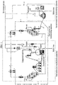
- FIG. 1 is a schematic diagram of a combined molten iron manufacturing apparatus according to an exemplary embodiment of the present invention.
- a first molten iron manufacturing apparatus in a combined molten iron manufacturing apparatus configured by a plurality of reaction furnaces that directly uses fine or compacted general coals or fine iron-containing ores may include a first fluidized reduction furnace constituted in multiple stages that reduces fine ore to convert the reduced fine ore to fine reduced iron, a plurality of hot compacting devices B that manufactures the fine reduced iron emitted from the first fluidized reduction furnace A to hot reduced compacted iron, a conveying device D that conveys the hot reduced compacted iron crushed with a predetermined size, a compacted iron charging device E for continuously supplying the hot reduced compacted iron conveyed by the conveying device D to a melter-gasifier G and a compacted general coal charging device F for continuously supplying compacted general coal to the melter-gasifier G, a melter-gasifier G that melts the hot reduced compacted iron supplied from the compacted iron charging device E by using hot
- a second molten iron manufacturing apparatus of the combined molten iron manufacturing apparatus may include a iron-bath type melting reduction furnace a that manufactures a fine iron-containing material and pulverized coal which are injected to the inner portion as molten iron and slag through reactions such as dissolution, combustion, and melting reduction therein to discharge the manufactured molten iron and slag to the outside, a hot blast furnace b that manufactures hot blast which is injected to the melting reduction furnace a as a secondary combustion oxidant, and a cleaning device d that cools and cleans the gas discharged from the melting reduction furnace a.
- the combined molten iron manufacturing apparatus may include a third molten iron manufacturing apparatus that is provided between the first molten iron manufacturing apparatus and the second molten iron manufacturing apparatus to connect the first molten iron manufacturing apparatus and the second molten iron manufacturing apparatus, branch some of the reducing gas generated from the melter-gasifier G of the first molten iron manufacturing apparatus and supplied to the first fluidized reduction furnace A, and reduce fine ore at a predetermined level by using the branched reducing gas to supply the reduced fine ore as an iron source of the second molten iron manufacturing apparatus.
- the third molten iron manufacturing apparatus may include an oxygen mixing furnace 2 that is provided on a pipe 30 supplying hot reducing gas to the first fluidized reduction furnace A of the first molten iron manufacturing apparatus through the dust circulation device H of the first molten iron manufacturing apparatus to inject oxygen into the hot reducing gas, a pipe 31 that is provided at the rear end of the oxygen mixing furnace 2 to branch some of the reducing gas, and a second fluidized reduction furnace 1 that is connected to the pipe 31, receives some the branched reducing gas from the pipe to reduce a fine ore, and converts the reduced fine ore to a fine reductant.
- the second fluidized reduction furnace 1 may be configured in multiple stages of two stages or three stages or more.
- the combined molten iron manufacturing apparatus may sequentially provide a second sensible heat recovery device 3 that is connected to the rear end of the second fluidized reduction furnace 1 to recover sensible heat of the exhaust gas discharged from the second fluidized reduction furnace 1, a second dry dust collecting device 4 that is connected to the rear end of the second sensible heat recovery device 3 to separate scattering dust in the exhaust gas, and a second gas cooling device 5 that is connected to the rear end of the second dry dust collecting device 4 to cool the exhaust gas.
- the second fluidized reduction furnace 1 constituted in the multiple stages may include a fine reductant storage tank 20 that is connected to the lowermost second fluidized reduction furnace to store the fine reductant discharged from the second fluidized reduction furnace 1 through a pipe 19, and a fine reductant transporting device 21 that is connected to the lower end of the fine reductant storage tank 20 to inject the fine reductant into the iron-bath type melting reduction furnace a of the second molten iron manufacturing apparatus through a fine reductant transporting pipe 10 connecting the fine reductant storage tank 20 and the iron-bath type melting reduction furnace a of the second molten iron manufacturing apparatus from the fine reductant storage tank 20.
- a first transporting device 6 and a first transporting pipe 7 connecting the first transporting device 6 and the fine reductant transporting pipe 10 may be provided to inject dusts separated from the first dry dust collecting device K into the iron-bath type melting reduction furnace a of the second molten iron manufacturing apparatus together with the fine reductant discharged from the second fluidized reduction furnace 1.
- a second transporting device 8 and a second transporting pipe 9 connecting the second transporting device 8 and the fine reductant transporting pipe 10 may be provided to inject dusts separated from the second dry dust collecting device 4 into the iron-bath type melting reduction furnace a of the second molten iron manufacturing apparatus together with the fine reductant discharged from the second fluidized reduction furnace 1.
- the second molten iron manufacturing apparatus may include a hot blast furnace fuel gas supply pipe 18 which is connected to the hot blast furnace b by combining the exhaust gases of the first fluidized reduction furnace A and the second fluidized reduction furnace 1 of the first molten iron manufacturing apparatus and then branching the exhaust gases at the line rear end branched to the by-product gas line in order to supply required fuel to the hot blast furnace b.
- the reducing gas generated from the melter-gasifier G of the first molten iron manufacturing apparatus is combined with the CO 2 removing gas supplied from the CO 2 removing device M and then passes through the dust circulation device H, and in this process, the dust in the reducing gas is removed.
- Some of the reducing gas from which the dust is removed is branched to the pressure control device I and the rest of the reducing gas is supplied to the first fluidized reduction furnace A of the first molten iron manufacturing apparatus through the pipe 30 as hot reducing gas.
- the oxygen mixing furnace 2 is provided, and the oxygen is injected into the oxygen mixing furnace 2 to combust some of the hot reducing gas flowing into the oxygen mixing furnace 2 and increase the temperature of the hot reducing gas by the combustion heat.
- the temperature of the hot reducing gas at the rear end of the oxygen mixing furnace 2 may be approximately 700 to 780°C in order to prevent adhesion of the fine ores in the first fluidized reduction furnace A and the second fluidized reduction furnace 1 of the third molten iron manufacturing apparatus to which the hot reducing gas is supplied.
- the hot reducing gas heated to the temperature is branched to the pipe 31 from the pipe 30 and then supplied to the second fluidized reduction furnace 1.
- the second fluidized reduction furnace 1 is constituted in the multiple stages (in FIG. 1 , for example, constituted in three stages), and the fine ore and supplementary raw materials are supplied to the uppermost second fluidized reduction furnace of the multi-stage second fluidized reduction furnace 1, hot gas supplied to the lowermost second fluidized reduction furnace of the multi-stage second fluidized reduction furnace 1 and a counter flow type, that is, the fine ore and supplementary raw materials are supplied from the uppermost end to the lowermost end and the hot gas is supplied from the lowermost end to the uppermost end to cross each other and contact each other.
- the fine ore and supplementary raw materials are reduced and fired to be converted to the fine reductant.
- the fine reductant is discharged from the lowermost second fluidized reduction furnace of the second fluidized reduction furnace 1 and stored in the fine reductant storage tank 20, injected into the iron-bath type melting reduction furnace a of the second molten iron manufacturing apparatus through the fine reductant transporting pipe 10 by the transporting device 21 provided at the lower end of the fine reductant storage tank 20, dissolved in the iron-bath type melting reduction furnace a, and then converted to molten iron and slag by melting reduction, slagging reaction, and the like.
- a reduction rate of the fine reduced ore included in the fine reductant discharged from the lowermost end of the second fluidized reduction furnace 1 is preferably about 60 to 70%.
- the reason is that at the reduction rate of 60 to 70% or more, adhesion of ores occurs, and at the reduction rate of 60 to 70% or less, energy required for the melting reduction and slagging of the fine reductant in the iron-bath type melting reduction furnace a of the second molten iron manufacturing apparatus is increased.
- the second fluidized reduction furnace 1 may be constituted in multiple stages, for example, two to three stages.
- the exhaust gas discharged from the second fluidized reduction furnace 1 is cooled through the second sensible heat recovery device 3, and then the dust included in the exhaust gas is separated through the second dry dust collecting device 4, cooled up to room temperature in the second gas cooling device 5, and discharged from the first fluidized reduction furnace A of the first molten iron manufacturing apparatus.
- the dust is removed through the first sensible heat recovery device J, the first dry dust collecting device K and the first gas cooling device L and combined with the cooled gas.
- Some of the combined gas is supplied to the CO 2 removing device M and the rest of the combined gas is combined with the gas discharged through the pressure control device I to be discharged to the by-product gas line.
- the first transporting device 6 and the second transporting device 7 are provided, respectively.
- the first transporting device 6 and the second transporting device 7 are connected with the fine reductant transporting pipe 10 through the first and second transporting pipes 7 and 9 by receiving the dust separated from the exhaust gas of the first fluidized reduction furnace A and the second fluidized reduction furnace 1 from the first dry dust collecting device K and the second dry dust collecting device 4 to be mixed with the fine reductant in the fine reductant transporting pipe 10 and then injected into the iron-bath type melting reduction furnace a.
- the first molten iron manufacturing apparatus is stable, and in order to produce the molten iron at high efficiency, as the used fine ores and coals, generally, high-rank ores having a relatively large iron content and metallurgy coals having a high coking property were used as illustrated in Tables 1 to 3 below.
- the third molten iron manufacturing apparatus used supplementary raw materials having the same composition as the first molten iron manufacturing apparatus.
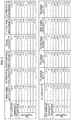
- FIGS. 2 and 3 are a process flowchart and a table illustrating property ratios of gases as an example of a process of manufacturing molten iron of 180 ton per hour in the first molten iron manufacturing apparatus and manufacturing molten iron of 100 ton per hour in the second molten iron manufacturing apparatus by using the third molten iron manufacturing apparatus of the combined molten iron manufacturing apparatus.
- Tables 6 to 9 below are composition tables illustrating contents of main components of molten iron and slag produced in the first molten iron manufacturing apparatus and the second molten iron manufacturing apparatus according to the exemplary embodiment of the present invention, respectively.
- [Table 6] Composition of produced molten iron of first molten iron manufacturing apparatus C Si p Mn S 4.500 0.500 0.059 0.150 0.047
- [Table 7] Composition of produced slag of first molten iron manufacturing apparatus SiO2 Al2O3 CaO MgO FeO S 30.731 17.695 36.893 10.516 0.488 1.226
- Table 8 Composition of produced molten iron of second molten iron manufacturing apparatus C Si P Mn S 4.000 0.100 0.090 0.000 0.076
- [Table 9] Composition of produced slag of second molten iron manufacturing apparatus SiO2 Al2O3 CaO MgO FeO S 32.807 18.359 42.649 2.450 2.988 0.303
- the second molten iron manufacturing apparatus As compared with the first molten iron manufacturing apparatus, low-cost fuel and raw materials were used and the impurity contents such as S and P in the molten iron are increased, but may be generally removed in a refining process.
- the molten iron is stably produced at high efficiency by using the relatively high-cost fuel and raw materials.
- the hot reducing gas generated stably in the first molten iron manufacturing apparatus is used and thus, the stable fine reductant of approximately 60 to 70% is manufactured by using the low-rank fine ores and supplementary raw materials from the second fluidized reduction furnace 1.
- the fine reductant is supplied as an iron source of the iron-bath type melting reduction furnace a of the second molten iron manufacturing apparatus to stably produce molten iron even by using low-cost anthracite as described above in the second molten iron manufacturing apparatus.
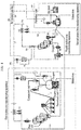
- FIG. 4 is a schematic diagram of a combined molten iron manufacturing apparatus according to another exemplary embodiment of the present invention.
- a first molten iron manufacturing apparatus in a combined molten iron manufacturing apparatus configured by a plurality of reaction furnaces that directly uses fine or compacted general coals or fine iron-containing ores may include a first fluidized reduction furnace A constituted in multiple stages that reduces fine ore to convert the reduced fine ore to fine reduced iron, a plurality of hot compacting devices B that manufactures the fine reduced iron emitted from the first fluidized reduction furnace A to hot reduced compacted iron, a conveying device D that conveys the hot reduced compacted iron crushed with a predetermined size, a compacted iron charging device E for continuously supplying the hot reduced compacted iron conveyed by the conveying device D to a melter-gasifier G and a compacted general coal charging device F for continuously supplying compacted general coal to the melter-gasifier G, a melter-gasifier G that melts the hot reduced compacted iron supplied from the compacted iron charging device E by using
- a second molten iron manufacturing apparatus of the combined molten iron manufacturing apparatus may include a iron-bath type melting reduction furnace a that manufactures a fine iron-containing material and pulverized coal which are injected to the inner portion as molten iron and slag through reactions such as dissolution, combustion, and melting reduction therein to discharge the manufactured molten iron and slag to the outside, a hot blast furnace b that manufactures hot blast which is injected to the melting reduction furnace a as a secondary combustion oxidant, a second sensible heat recovery device c for recovering sensible heat of the exhaust gas discharged from the melting reduction furnace a, and a cleaning device d that cools and cleans the gas discharged from the melting reduction furnace a.
- the combined molten iron manufacturing apparatus may include a fourth molten iron manufacturing apparatus that is provided between the first molten iron manufacturing apparatus and the second molten iron manufacturing apparatus to connect the first molten iron manufacturing apparatus and the second molten iron manufacturing apparatus, partially extracts and removes a CO 2 component included in the final by-product gas of the first molten iron manufacturing apparatus, manufactures hot reducing gas by heating the CO 2 component, and then reduces and sinters the fine ore, the supplementary raw materials, and the like at a predetermined level by using the reducing gas to manufacture a fine reductant and supply the fine reductant as an iron source of the second molten iron manufacturing apparatus.
- the fourth molten iron manufacturing apparatus may include a compressor 101 that is connected with a by-product gas pipe 120 in which by-product gas generated from the first molten iron manufacturing apparatus flows to compress the by-product gas, a second CO 2 removing device 102 that is connected with the compressor 101 to remove the CO 2 component in the compressed gas from the compressor 101, a heat exchanger 104 and a gas heater 105 which are connected with the second CO 2 removing device 102 and provided for heating CO 2 removing gas discharged from the second CO 2 removing device 102 and manufacturing hot reducing gas, an oxygen mixing furnace 106 that is connected with the gas heater 105 to inject oxygen into the hot reducing gas, and a second fluidized reduction furnace 107 that is connected with the oxygen mixing furnace 106 and reduces and fires the fine ore and the supplementary raw materials by supplying the hot reducing gas.
- the second fluidized reduction furnace 107 may be configured in multiple stages of two stages or three stages or more.
- the combined molten iron manufacturing apparatus may sequentially provide a second dry dust collecting device 115 that is connected to the rear end of the heat exchanger 104 and discharged from the second fluidized reduction furnace 107 to separate scattering dust in the exhaust gas after passing through the heat exchanger 104, and a second gas cooling device 116 that is connected to the rear end of the second dry dust collecting device 115 to cool the exhaust gas.
- the combined molten iron manufacturing apparatus may provides a gas pipe 121 that is connected to the rear end of the second gas cooling device 116 to circulate some of the exhaust gas to the second CO 2 removing device 102, a final exhaust gas pipe 124 that is connected to the rear end of the second gas cooling device 116 to discharge the rest of the exhaust gas to the outside, and a gas pipe 126 that connects the second CO 2 removing device 102 and the final exhaust gas pipe 124 to discharge the CO 2 separated from the second CO 2 removing device 102 to the outside.
- the second fluidized reduction furnace 107 may include a fine reductant storage tank 109 for storing the fine reductant discharged from the lowermost fluidized reduction furnace through the pipe 108, and a fine reductant transporting device 110 that injects the fine reductant into the iron-bath type melting reduction furnace a of the second molten iron manufacturing apparatus through a fine reductant transporting pipe 111 connecting the fine reductant storage tank 109 and the iron-bath type melting reduction furnace a from the fine reductant storage tank 109.
- a first transporting device 113 and a first transporting pipe 114 connecting the first transporting device 113 and the fine reductant transporting pipe 111 may be provided to inject dusts separated from the first dry dust collecting device K into the iron-bath type melting reduction furnace a of the second molten iron manufacturing apparatus together with the fine reductant discharged from the second fluidized reduction furnace 7.
- a second transporting device 117 and a second transporting pipe 118 connecting the second transporting device 117 and the fine reductant transporting pipe 111 may be provided to inject dusts separated from the second dry dust collecting device 115 into the iron-bath type melting reduction furnace a of the second molten iron manufacturing apparatus together with the fine reductant discharged from the second fluidized reduction furnace 107.
- the pipe 120 may include a fuel gas supply pipe 119 which is branched at a front end of a point where gas containing CO 2 removed from the second CO 2 removing device 102 and gas discharged from the second molten iron manufacturing apparatus are combined and connected to the hot blast furnace b, the gas heating furnace 105, and the like.
- the by-product gas generated from the first molten iron manufacturing apparatus flows through the pipe 20, and is combined with some of the exhaust gas of the second fluidized reduction furnace 107 flowing through the pipe 121, supplied to the compressor 101, and supplied to the second CO 2 removing device 102 connected with the compressor 101 after boosting to remove CO 2 in the gas.
- the CO 2 concentration in the CO 2 removing gas discharged from the second CO 2 removing device 102 may be approximately 3 to 15%.
- the reason is that in order to make the CO 2 concentration to be 3% or less, costs required for installation and operation of the second CO 2 removing device 102 is too high, and further, when the CO 2 concentration is 15% or more, reducibility of the CO 2 removing gas is excessively deteriorated and thus, reduction of the ores in the second fluidized reduction furnace 107 is not smoothly performed.
- the CO 2 removed from the by-product gas of the first molten iron manufacturing apparatus and the exhaust gas of the second fluidized reduction furnace 107 in the CO 2 removing device 102 is discharged to the outside through a separate gas pipe 126.
- the CO 2 removing gas discharged from the second CO 2 removing device 102 is heated by contacting the hot gas discharged from the second fluidized reduction furnace 107 through a heat exchange tube provided in the heat exchanger 104 while passing through the heat exchanger 104, and then heated by contacting hot combustion gas generated by combusting the exhaust gas supplied through the gas pipe 119 in the gas heater 105 through a heat exchange tube provided in the gas heater 105.
- the gas heating temperature in the gas heater 105 may be approximately 400 to 450°C. The reason is that since a large amount of CO gas is included in the CO 2 removing gas, at the temperature or more, metal dusting occurs by the CO gas and thus, damage to the heat exchange tube provided in the gas heater 105 is caused.
- the gas heated to approximately 400 to 450°C in the gas heater 105 is partially combusted in the oxygen mixing furnace 106 by oxygen injected from the outside of the oxygen mixing furnace 106 and heated as the combustion heat.
- the temperature of the gas discharged from the oxygen mixing furnace 106 may be approximately 700 to 780°C in order to prevent coherence of the fine ores in the second fluidized reduction furnace 107 from which the gas is supplied.
- the hot gas heated at the temperature is supplied to the second fluidized reduction furnace 107 at the rear end of the oxygen mixing furnace 106.
- the second fluidized reduction furnace 107 is constituted in the multiple stages (in FIG. 1 , for example, constituted in three stages), and the fine ore and the supplementary raw materials are supplied to the uppermost second fluidized reduction furnace of the multi-stage second fluidized reduction furnace 107, hot gas supplied to the lowermost second fluidized reduction furnace of the multi-stage second fluidized reduction furnace 107 and a counter flow type, that is, the fine ore and supplementary raw materials are supplied from the uppermost end to the lowermost end and the hot gas is supplied from the lowermost end to the uppermost end to cross each other and contact each other.
- the fine ore and supplementary raw materials are reduced and fired to be converted to the fine reductant.
- the fine reductant is discharged from the lowermost second fluidized reduction furnace of the second fluidized reduction furnace 107 and conveyed and stored to the fine reductant storage tank 109, injected into the iron-bath type melting reduction furnace a of the second molten iron manufacturing apparatus through the fine reductant transporting pipe 111 by the transporting device 110 provided at the lower end of the fine reductant storage tank 108, dissolved in the iron-bath type melting reduction furnace a, and then converted to molten iron and slag by melting reduction, slagging reaction, and the like.
- a reduction rate of the fine reduced ore included in the fine reductant discharged from the lowermost end of the second fluidized reduction furnace 107 is preferably about 60 to 70%.
- the reason is that at the reduction rate of 60 to 70% or more, adhesion of ores occurs, and at the reduction rate of 60 to 70% or less, energy required for the melting reduction and slagging of the fine reductant in the iron-bath type melting reduction furnace a in the second molten iron manufacturing apparatus is excessively increased.
- the second fluidized reduction furnace 107 may be constituted in multiple stages, for example, two to three stages.
- the exhaust gas discharged from the second fluidized reduction furnace 107 is cooled by heat exchange with the CO 2 removing gas while passing through the heat exchanger 104 as described above, the dust included in the exhaust gas is separated through the second dry dust collecting device 115, some of the exhaust gas after cooling to room temperature in the second gas cooling device 116 is branched, combined with the by-product gas of the first molten iron manufacturing apparatus through the pipe 121 as described above to be re-supplied to the second CO 2 removing device 102, the rest of the exhaust gas is discharged to the outside through the pipe 124, and then some of the gas flowing in the pipe 124 is supplied as the fuel of the gas heater 105 and the hot blast furnace b of the second molten iron manufacturing apparatus through the pipe 119.
- the first transporting device 113 and the second transporting device 117 are provided, respectively.
- the first transporting device 113 and the second transporting device 117 are connected with the fine reductant transporting pipe 111 through the first and second transporting pipes 114 and 118 by receiving the dust separated from the exhaust gas of the first fluidized reduction furnace A and the second fluidized reduction furnace 7 from the first dry dust collecting device K and the second dry dust collecting device 115 to be mixed with the fine reductant in the fine reductant transporting pipe 11 and then injected into the iron-bath type melting reduction furnace a.
- the first molten iron manufacturing apparatus is stable, and in order to produce the molten iron at high efficiency, as the used fine ores and coals, generally, high-rank ores having a relatively large iron content and metallurgy coals having a high coking property were used as illustrated in Tables 11 to 13 below.
- the fourth molten iron manufacturing apparatus used supplementary raw materials having the same composition as the first molten iron manufacturing apparatus.
- FIG. 5 is a process flowchart according to a material flow and a table illustrating property ratios of gases as an example of a process of manufacturing molten iron of 100 ton per hour in the second molten iron manufacturing apparatus by using the fourth molten iron manufacturing apparatus according to another exemplary embodiment of the present invention using the exhaust gas of the first molten iron manufacturing apparatus that manufactures molten iron of 180 ton per hour.
- Tables 16 to 19 below are composition tables illustrating contents of main components of molten iron and slag produced in the first molten iron manufacturing apparatus and the second molten iron manufacturing apparatus according to another exemplary embodiment of the present invention, respectively.
- [Table 16] Composition of produced molten iron of first molten iron manufacturing apparatus C Si P Mn S 4.500 0.500 0.059 0.150 0.047
- [Table 17] Composition of produced slag of first molten iron manufacturing apparatus SiO2 Al2O3 CaO MgO FeO S 30.731 17.695 36.893 10.516 0.488 1.226
- Table 18 Composition of produced molten iron of second molten iron manufacturing apparatus C Si P Mn S 4.000 0.100 0.090 0.000 0.076
- [Table 19] Composition of produced slag of second molten iron manufacturing apparatus SiO2 Al2O3 CaO MgO FeO S 32.807 18.359 42.649 2.450 2.988 0.303
- the second molten iron manufacturing apparatus As compared with the first molten iron manufacturing apparatus, low-cost fuel and raw materials were used and the impurity contents such as S and P in the molten iron are increased, but may be generally removed in a refining process.
- the molten iron is stably produced at high efficiency by using the relatively high-cost fuel and raw materials.
- the hot reducing gas generated stably in the first molten iron manufacturing apparatus is used and thus, the stable fine reductant of approximately 60 to 70% is manufactured by using the low-rank fine ores and supplementary raw materials from the second fluidized reduction furnace 1.
- the fine reductant is supplied as an iron source of the iron-bath type melting reduction furnace a of the second molten iron manufacturing apparatus to stably produce molten iron even by using low-cost anthracite as described above in the second molten iron manufacturing apparatus.
Landscapes
- Chemical & Material Sciences (AREA)
- Engineering & Computer Science (AREA)
- Manufacturing & Machinery (AREA)
- Materials Engineering (AREA)
- Metallurgy (AREA)
- Organic Chemistry (AREA)
- Dispersion Chemistry (AREA)
- Manufacture Of Iron (AREA)
- Waste-Gas Treatment And Other Accessory Devices For Furnaces (AREA)
Abstract
Description
- The present invention relates to a combined molten iron manufacturing apparatus, and more particularly, to a combined molten iron manufacturing apparatus configured by combining reactors that perform reduction, dissolution, and the like of a plurality of iron-containing materials having various forms and functions so as to directly use fuel and raw materials with various ranks and particle sizes when manufacturing molten iron by directly using fine or compacted general coals or fine iron-containing ores.
- Currently, about 60% of the worldwide production of iron has been produced by a blast furnace method, which has been developed from the 14th century. The blast furnace method is a method for manufacturing molten iron in which coke and the like manufactured by using iron ores and bituminous coal as raw materials which are subject to a sintering process are added in a blast furnace, and oxygen is supplied to the furnace to reduce the iron ore to iron.
- As such, since the blast furnace method, which forms its majority of a molten iron producing apparatus requires a raw materials that has a strength of a predetermined level or more due to the reaction characteristic and has a particle diameter capable of ensuring ventilation in the furnace, as described above, a carbon source used as fuel and a reductant depends on the coke processed by specific coking coal and an iron source depends on sintered ore that is subjected to a series of compacting processes.
- Accordingly, in the current blast furnace method, since raw material pretreatment facilities such as coke production facilities and sintering facilities are necessarily accompanied, it is necessary not only to construct additional facilities other than the blast furnace but also to install environmental pollution prevention facilities for various environmental pollutants generated in the additional facilities, and as a result, the investment cost is consumed in a large amount and the manufacturing cost is rapidly increased.
- In order to solve the problem of the blast furnace method, steel mills all over the world make a lot of efforts to develop a melting reduction steelmaking method for manufacturing molten iron by directly using general coals as a fuel and a reductant and as an iron source, fine ores that occupy more than 80% of the worldwide production of ores.
- As an example of the melting reduction steelmaking method, in European Patent Publication No.
1,689,892 , there is disclosed an apparatus fro manufacturing molten iron directly using fine or lump coals and fine iron-containing ores and the method thereof. - In European Patent Publication No.
1,689,892 , an apparatus fro manufacturing molten iron directly using fine or lump coals and fine iron-containing ores is configured by a multi-stage fluidized reduction furnace that reduces and fires fine iron-containing ores and supplementary raw materials by contacting hot reducing gas; a hot compacting device that compacts the fine reduced iron discharged from the fluidized reduction furnace to manufacture hot reduced compacted iron; and a melter-gasifier in which briquette coals compacted and manufactured from fine general coals and compacted general coals are continuously supplied to form a coal filling layer with a predetermined height therein, oxygen and a pulverized coal material are injected through a plurality of fans formed at the lower end of the outer wall of the coal filling layer, the pulverized coal material and the compacted coals in the coal filling layer are combusted by the oxygen, hot reduced compacted iron which is manufactured in the hot compacting device by sensible heat generated while hot gas formed by the combustion lifts the filling layer, charged to the upper portion of the coal filling layer, and then descends in the coal filling layer and supplementary raw materials injected to the top of the coal filling layer with the hot reduced compacted iron are heated, melted, and slagged to manufacture molten iron and slag and integrate the manufactured molten iron and slag below the coal filling layer, and then the molten iron and slag are periodically discharged to the outside, the hot gas passing through the melted coal filling layer is discharged, and the hot gas is supplied to the multi-stage fluidized reduction furnace as reducing gas required for reduction of the fine iron-containing ores. - Further, there is provided an exhaust gas reformation circulation device in which the gas discharged to the multi-stage fluidized reduction furnace is cooled through a dust collecting device, and then some of the gas is branched and compressed and mixed with the hot reducing gas discharged from the melter-gasifier after removing CO2 to additionally supply the reducing gas to the multi-stage fluidized reduction furnace. In the exhaust gas reformation circulation device, the CO2-removed gas is supplied to a final front end of the fluidized reduction furnace which corresponds to the lowermost portion in the multi-stage fluidized reduction furnace and to which the reducing gas is directly supplied.
- In the molten iron manufacturing process, the reduction of 60 to 70% of the iron ores is performed by indirect reduction by the reducing gas supplied from the melter-gasifier in the multi-stage fluidized reduction furnace, the reduction of the
rest 30 to 40% of the iron ores is performed by indirect reduction by coal combustion gas which lifts the coal filling layer in the coal filling layer in the melter-gasifier after manufacturing the iron ores to the hot reduced compacted iron and then injecting the hot reduced compacted iron to the melter-gasifier and direct reduction by a carbon component of the coal in the coal filling layer and the coal combustion gas. , - Accordingly, in order to smoothly perform the reduction of the iron ores, it is important to smoothly contact the reducing gas/fine iron ores in the fluidized reduction furnace, the hot coal combustion gas in the melter-gasifier, and the hot reduced compacted iron.
- It is determined that the gas/fine ore contact in the fluidized reduction furnace has no matter when considering high mixing efficiency of the fluidized reduction furnace, but the contact of the gas/hot reduced compacted iron in the coal filling layer of the melter-gasifier is influenced by the gas flow distribution in the coal filling layer, and a factor determining the gas flow distribution is a pore distribution in the coal filling layer.
- Further, the pore distribution in the coal filling layer acts as a crucial factor even when molten iron and slag generated by heating, melting, and slagging the hot reduced compacted iron and the supplementary raw materials in the coal filling layer pass through the coal filling layer and are discharged to the lower portion of the coal filling layer, thereby smoothly maintaining the flow of the molten iron/slag.
- The pore distribution in the coal filling layer is largely influenced by a high-temperature property of the coals forming the coal filling layer to limit a rank of the coal which is usable in the molten iron manufacturing apparatus.
- Further, as described above, the molten iron and slag need to pass through the coal filling layer to be discharged to the outside of the melter-gasifier, and in the molten iron and the slag, particularly, an amount and flowability of the slag is important. The shape of the slag is determined according to an amount, a composition, and the like of the gangue in the ores used as the raw material to limit a rank of the coal which is usable in the molten iron manufacturing apparatus.
- In addition, in the case of using ores containing a large amount of phosphorous component depending on a high-reducing atmosphere in the coal filling layer, there is a problem in that a large amount of phosphorous component which is difficult to refine in the produced molten iron, and thus even in order to maintain the quality of the produced molten iron, there are restrictions on the used raw ores.
- When showing the published data on an actual operation result of the molten iron manufacturing apparatus disclosed in European Patent Publication No.
1,689,892 , the molten iron manufacturing apparatus is very stably operated and a rank of usable ores and a rank range of coals are gradually expanded compared with an existing blast furnace method, but it is reported that the rank of ores and the rank of coals usable in the molten iron manufacturing apparatus are significantly limited. - Meanwhile, another example of the melting reduction steelmaking method is disclosed in US Patent Registration Nos.
6332745B1 ,US 6379422B1 andUS 6602321B1 . - In US Patent Registration Nos.
6332745B1 ,US 6379422B1 andUS 6602321B1 , the molten iron manufacturing apparatus is configured by a molten-bath type reactor constituted by a molten iron layer, a slag layer formed on the molten iron layer, and a gas layer formed on the slag layer; a secondary combustion lance configured to inject hot blast which is formed from the upper portion of the molten-bath type reactor to the upper portion of the slag layer and in which oxygen is enriched to the upper portion of the slag layer; a fine coal injection lance and a fine ore injection lance configured to inject fine coals and fine ores from the outside at a boundary point, which is formed up to the upper portion of the molten iron layer of the lower portion of the slag layer, that is, the boundary point of the slag layer/molten iron layer by passing through the side of the molten-bath type reactor and passing through the slag layer in the molten-bath type reactor; a preliminary reduction furnace formed to preheat/preliminarily reduce the fine ores injected to the molten-bath type reactor by using some of the hot gas discharged from the molten-bath type reactor; a scrubber for cooling/cleaning the exhaust gas to the molten-bath type reactor other than the gas supplied to the preliminary reducing furnace; a scrubber for cooling/cleaning the exhaust gas to the molten-bath type reactor other than the gas supplied to the preheating furnace; and a hot blast furnace provided for forming hot blast supplied through the secondary combustion lance. - In the molten iron manufacturing apparatus, the reduction of iron ores is performed in a molten state in the molten bath formed in the molten-bath type reactor. To this end, coal as a reductant required for the reduction is supplied into the molten bath, heat required for the reduction is supplied as heat generated in combustion, that is, secondary combustion generated by combusting gas generated by a reduction of the iron ore and the coal in the molten bath with an oxygen-enriched hot blast supplied from the secondary combustion lance.
- The reducibility of the hot gas which is discharged from the molten-bath type reactor and supplied to the preliminary reducing furnace by using the hot blast as the combustion and oxidizing gas is very low, and the reduction of the ores that proceeds in the preliminary reducing furnace is limited to 20% or less. The ores and the coals are pulverized with 1 mm or less and injected so that rapid melting and reaction in the molten bath are performed. The molten iron and the slag generated by the reaction are continuously or periodically discharged through respective outlets.
- In the molten iron manufacturing apparatus, all reactions and molten iron/slag discharge are performed in a molten state, and compared with the molten iron manufacturing apparatus disclosed in European Patent Publication No.
1,689,892 , limitation on the ranks of usable coals and ores is very low, and as described above, it is determined that heat efficiency is very high by simultaneously performing melting and reduction and actively using the secondary combustion. - However, when showing the published data on an actual operation result of the molten iron manufacturing apparatus disclosed in US Patent Registration No.
US 6332745B1 and the like, various equipment problems and operational problems are reported. - In the problems, a problem that has the greatest effect on utilization and productivity is that the operation of connecting the molten-bath type reactor with the preliminary reducing furnace connected thereto is not smoothly performed. It is reported that in the molten-bath type reactor, the temperature and the shape of the gas generated after secondary combustion are instable, and thus, the fluctuation of the heating and reduction reaction of the ores in the preliminary reduction furnace using the gas becomes severe, the shape of the preliminary reducing ore supplied to the molten-bath type reactor from the preliminary reducing furnace is changed, and as a result, a vicious cycle in which the melting reduction reaction and the secondary combustion reaction of the ores in the molten-bath type reactor become unstable occurs.
- Further, it is reported that there are problems in that even when the linked operation is temporarily smooth, the reduction rate of the preliminary reducing ore supplied to the molten-bath type reactor from the preliminary reducing furnace is too low and thus the consumption of the coal required for the melting reduction of the preliminary reducing ore is too high compared with a target, and further, the concentration of slag oxidized iron in the molten-bath type reactor is too high and thus, the refractory material in the molten-bath type reactor is excessively eroded.
- Various methods for solving the problems are applied, but it is reported that an improvement effect is slight and further, the thermal efficiency and the reaction efficiency are gradually decreased due to the above methods and the economical efficiency is lowered.
- As described above, development of various melting reduction steelmaking methods for replacing the blast furnace is independently performed and operation results of the molten iron manufacturing apparatuses according to the respective melting reduction steelmaking methods have been reported and have reached the level capable of grasping the merits, drawbacks, and technical performance of each of the respective melting reduction steelmaking methods.
- Accordingly, at present, in order to maximize merits of the molten iron manufacturing apparatuses, a combined molten iron manufacturing process (apparatus) configured by combining a plurality of molten iron manufacturing processes (apparatuses) by applying a new mediation process (apparatus).
- The present invention has been made in an effort to provide a new molten iron manufacturing apparatus configured by combining two molten iron manufacturing apparatuses through a fluidized reduction furnace which is additionally configured in a molten iron manufacturing apparatus based on the fluidized reduction furnace and a coal filling-type melter-gasifier and a molten iron manufacturing apparatus based on a molten-bath type melting reduction furnace, and more particularly, to provide a combined molten iron manufacturing apparatus configured by combining two molten iron manufacturing apparatuses through a separate fluidized reduction furnace which is additionally configured in a molten iron manufacturing apparatus based on the fluidized reduction furnace and a coal filling-type melter-gasifier and a molten iron manufacturing apparatus based on a molten-bath type melting reduction furnace, thereby stably producing molten iron by using conventional metallurgical fuel and raw materials in the molten iron manufacturing apparatus based on the fluidized reduction furnace and the coal filling-type melter-gasifier and stably producing molten iron by using conventional metallurgical unsuitable low-grade fuel and raw materials in the molten iron manufacturing apparatus based on the molten-bath type melting reduction furnace connected thereto.
- Further, the present invention has been made in an effort to provide a new molten iron manufacturing apparatus configured by combining two molten iron manufacturing apparatuses through a fluidized reduction furnace which is additionally configured in a molten iron manufacturing apparatus based on the fluidized reduction furnace and a coal filling-type melter-gasifier and a molten iron manufacturing apparatus based on a molten-bath type melting reduction furnace, and more particularly, to a combined molten iron manufacturing apparatus configured to stably operate the molten-bath type melting reduction furnace by partially extracting and removing a CO2 component included in final by-product gas of the molten iron manufacturing apparatus in the molten iron manufacturing apparatus based on the fluidized reduction furnace and the coal filling-type melter-gasifier, heating the CO2 component, manufacture hot reducing gas, and then supplying the hot reducing gas to a separate multi-stage type fluidized reduction furnace, reducing and firing fine ores and supplementary raw materials in the multi-stage type fluidized reduction furnace at a predetermined to manufacture a fine reductant, and supplying the fine reductant to the molten iron manufacturing apparatus based on the molten-bath type melting reduction furnace, thereby stably producing molten iron by using high-grade fuel and raw materials in the molten iron manufacturing apparatus based on the fluidized reduction furnace and the coal filling-type melter-gasifier and stably producing molten iron by using low-grade fuel and raw materials in the molten iron manufacturing apparatus based on the molten-bath type melting reduction furnace connected thereto.
- An exemplary embodiment of the present invention provides a combined molten iron manufacturing apparatus including: a first molten iron manufacturing apparatus including a first fluidized reduction furnace constituted in multiple stages that reduces fine ore to convert the reduced fine ore to fine reduced iron, a plurality of hot compacting devices that manufactures the fine reduced iron emitted from the first fluidized reduction furnace to hot reduced compacted iron, a conveying device that conveys the hot reduced compacted iron crushed with a predetermined size, a compacted iron charging device for continuously supplying the hot reduced compacted iron conveyed by the conveying device to a melter-gasifier and a compacted general coal charging device for continuously supplying compacted general coal to the melter-gasifier, a melter-gasifier that melts the hot reduced compacted iron supplied from the compacted iron charging device by using hot combust gas generated by combusting the compacted general coal supplied from the compacted general coal charging device and a pulverized coal material injected from the lower portion with oxygen and supplies reducing gas required in fine ore reduction in the first fluidized reduction furnace, a CO2 removing device that removes CO2 by branching some of exhaust gas of the first fluidized reduction furnace and then supplies the reducing gas to the first fluidized reduction furnace by adding the removed CO2 to the reducing gas supplied from the melter-gasifier, a dust circulation device that separates dust included in the reducing gas generated from the melter-gasifier to re-inject the dust to the melter-gasifier, a pressure control device that uniformly maintains pressure in the melter-gasifier by branching and cooling some of gases generated from the melter-gasifier according to a pressure change of the melter-gasifier and then discharging some of gases to a by-product gas line, a first sensible heat recovery device that recovers sensible heat of the exhaust gas discharged from the first fluidized reduction furnace, a first dry dust collecting device that separates scattering dust included in the exhaust gas discharged from the first fluidized reduction furnace, and a first gas cooling device that cools the exhaust gas discharged from the first fluidized reduction furnace;
a second molten iron manufacturing apparatus including an iron-bath type melting reduction furnace that manufactures a fine iron-containing material and pulverized coal which are injected to the inner portion as molten iron and slag through reactions such as dissolution, combustion, and melting reduction therein to discharge the manufactured molten iron and slag to the outside, a hot blast furnace that manufactures hot blast which is injected to the melting reduction furnace a as a secondary combustion oxidant, and a cleaning device that cools and cleans the gas discharged from the melting reduction furnace; and
a third molten iron manufacturing apparatus that is provided between the first molten iron manufacturing apparatus and the second molten iron manufacturing apparatus to connect the first molten iron manufacturing apparatus and the second molten iron manufacturing apparatus, branch some of the reducing gas generated from the melter-gasifier of the first molten iron manufacturing apparatus and supplied to the first fluidized reduction furnace, and reduces a fine ore at a predetermined level by using the branched reducing gas to supply the reduced fine ore as an iron source of the second molten iron manufacturing apparatus. - The third molten iron manufacturing apparatus may include an oxygen mixing furnace that is provided on a pipe supplying hot reducing gas to the first fluidized reduction furnace of the first molten iron manufacturing apparatus through the dust circulation device of the first molten iron manufacturing apparatus to inject oxygen into the hot reducing gas,
a pipe that is provided at the rear end of the oxygen mixing furnace to branch some of the reducing gas, and
a second fluidized reduction furnace that is connected to the pipe, receives some the branched reducing gas from the pipe to reduce a fine ore, and converts the reduced fine ore to a fine reductant. - The second fluidized reduction furnace may be configured in multiple stages of two stages or three stages or more.
- The combined molten iron manufacturing apparatus may further include a second sensible heat recovery device that is connected to the rear end of the second fluidized reduction furnace to recover sensible heat of the exhaust gas discharged from the second fluidized reduction furnace.
- The combined molten iron manufacturing apparatus may further include a second dry dust collecting device that is connected to the rear end of the second sensible heat recovery device to separate scattering dust in the exhaust gas.
- The combined molten iron manufacturing apparatus may further include a second gas cooling device that is connected to the rear end of the second dry dust collecting device to cool the exhaust gas.
- The second fluidized reduction furnace may include a fine reductant storage tank that is connected to the lowermost second fluidized reduction furnace to store the fine reductant discharged from the second fluidized reduction furnace through a pipe.
- The second fluidized reduction furnace may include a fine reductant transporting device that is connected to the lower end of the fine reductant storage tank to inject the fine reductant into the iron-bath type melting reduction furnace of the second molten iron manufacturing apparatus through a fine reductant transporting pipe connecting the fine reductant storage tank and the iron-bath type melting reduction furnace of the second molten iron manufacturing apparatus from the fine reductant storage tank.
- At the lower end of the first dry dust collecting device, a first transporting device and a first transporting pipe connecting the first transporting device and the fine reductant transporting pipe may be provided to inject dusts separated from the first dry dust collecting device into the iron-bath type melting reduction furnace of the second molten iron manufacturing apparatus together with the fine reductant discharged from the second fluidized reduction furnace.
- At the lower end of the second dry dust collecting device, a second transporting device and a second transporting pipe connecting the second transporting device and the fine reductant transporting pipe may be provided to inject dusts separated from the second dry dust collecting device into the iron-bath type melting reduction furnace of the second molten iron manufacturing apparatus together with the fine reductant discharged from the second fluidized reduction furnace.
- The combined molten iron manufacturing apparatus may further include a hot blast furnace fuel gas supply pipe which is connected to the hot blast furnace by combining the exhaust gases of the first fluidized reduction furnace and the second fluidized reduction furnace of the first molten iron manufacturing apparatus and then branching the exhaust gases at the line rear end branched to the by-product gas line in order to supply required fuel to the hot blast furnace.
- Another exemplary embodiment of the present invention provides a combined molten iron manufacturing apparatus including: a first molten iron manufacturing apparatus including a first fluidized reduction furnace constituted in multiple stages that reduces fine ore to convert the reduced fine ore to fine reduced iron, a plurality of hot compacting devices that manufactures the fine reduced iron emitted from the first fluidized reduction furnace to hot reduced compacted iron, a conveying device that conveys the hot reduced compacted iron crushed with a predetermined size, a compacted iron charging device for continuously supplying the hot reduced compacted iron conveyed by the conveying device to a melter-gasifier and a compacted general coal charging device for continuously supplying compacted general coal to the melter-gasifier, a melter-gasifier that melts the hot reduced compacted iron supplied from the compacted iron charging device by using hot combust gas generated by combusting the compacted general coal supplied from the compacted general coal charging device and a pulverized coal material injected from the lower portion with oxygen and supplies reducing gas required in fine ore reduction in the first fluidized reduction furnace, a CO2 removing device that removes CO2 by branching some of exhaust gas of the first fluidized reduction furnace and then supplies the reducing gas to the first fluidized reduction furnace by adding the removed CO2 to the reducing gas supplied from the melter-gasifier, a dust circulation device that separates dust included in the reducing gas generated from the melter-gasifier to re-inject the dust to the melter-gasifier, a pressure control device that uniformly maintains pressure in the melter-gasifier by branching and cooling some of gases generated from the melter-gasifier according to a pressure change of the melter-gasifier and then discharging some of gases to a by-product gas line, a first sensible heat recovery device that recovers sensible heat of the exhaust gas discharged from the first fluidized reduction furnace, a first dry dust collecting device that separates scattering dust included in the exhaust gas discharged from the first fluidized reduction furnace, and a first gas cooling device that cools the exhaust gas discharged from the first fluidized reduction furnace;
a second molten iron manufacturing apparatus including a iron-bath type melting reduction furnace that manufactures a fine iron-containing material and pulverized coal which are injected to the inner portion as molten iron and slag through reactions such as dissolution, combustion, and melting reduction therein to discharge the manufactured molten iron and slag to the outside; a hot blast furnace b that manufactures hot blast which is injected to the melting reduction furnace a as a secondary combustion oxidant, a second sensible heat recovery device c for recovering sensible heat of the exhaust gas discharged from the melting reduction furnace a, and a cleaning device d that cools and cleans the gas discharged from the melting reduction furnace, and
a fourth molten iron manufacturing apparatus that is provided between the first molten iron manufacturing apparatus and the second molten iron manufacturing apparatus to connect the first molten iron manufacturing apparatus and the second molten iron manufacturing apparatus, partially extracts and removes a CO2 component included in the final by-product gas of the first molten iron manufacturing apparatus, manufactures hot reducing gas by heating the CO2 component, and then reduces and sinters the fine ore, the supplementary raw materials, and the like at a predetermined level by using the reducing gas to manufacture a fine reductant and supply the fine reductant as an iron source of the second molten iron manufacturing apparatus. - The fourth molten iron manufacturing apparatus may include a compressor that is connected with a by-product gas pipe in which by-product gas generated from the first molten iron manufacturing apparatus flows to compress the by-product gas,
a second CO2 removing device that is connected with the compressor to remove the CO2 component in the compressed gas from the compressor,
a heat exchanger and a gas heater which are connected with the second CO2 removing device and provided for heating CO2 removing gas discharged from the second CO2 removing device and manufacturing hot reducing gas,
an oxygen mixing furnace that is connected with the gas heater to inject oxygen into the hot reducing gas, and
a second fluidized reduction furnace that is connected with the oxygen mixing furnace and reduces and fires the fine ore and the supplementary raw materials by supplying the hot reducing gas. - The second fluidized reduction furnace may be configured in multiple stages of two stages or three stages or more.
- The combined molten iron manufacturing apparatus may further include a second dry dust collecting device that is connected to the rear end of the heat exchanger and discharged from the second fluidized reduction furnace to separate scattering dust in the exhaust gas after passing through the heat exchanger.
- The combined molten iron manufacturing apparatus may further include a second gas cooling device that is connected to the rear end of the second dry dust collecting device to cool the exhaust gas.
- The combined molten iron manufacturing apparatus may further include a gas pipe that is connected to the rear end of the second gas cooling device to circulate some of the exhaust gas to the second CO2 removing device.
- The combined molten iron manufacturing apparatus may further include a final exhaust gas pipe that is connected to the rear end of the second gas cooling device to discharge the rest of the exhaust gas to the outside.
- The combined molten iron manufacturing apparatus may further include a gas pipe that connects the second CO2 removing device and the final exhaust gas pipe to discharge the CO2 separated from the second CO2 removing device to the outside.
- The second fluidized reduction furnace may include a fine reductant storage tank for storing the fine reductant discharged from the lowermost fluidized reduction furnace through the pipe.
- The second fluidized reduction furnace may include a fine reductant transporting device that injects the fine reductant into the iron-bath type melting reduction furnace of the second molten iron manufacturing apparatus through a fine reductant transporting pipe connecting the fine reductant storage tank and the iron-bath type melting reduction furnace from the fine reductant storage tank.
- At the lower end of the first dry dust collecting device, a first transporting device and a first transporting pipe connecting the first transporting device and the fine reductant transporting pipe may be provided to inject dusts separated from the first dry dust collecting device into the iron-bath type melting reduction furnace of the second molten iron manufacturing apparatus together with the fine reductant discharged from the second fluidized reduction furnace.
- At the lower end of the second dry dust collecting device, a second transporting device and a second transporting pipe connecting the second transporting device and the fine reductant transporting pipe may be provided to inject dusts separated from the second dry dust collecting device into the iron-bath type melting reduction furnace of the second molten iron manufacturing apparatus together with the fine reductant discharged from the second fluidized reduction furnace.
- In order to supply required fuel to the gas heating furnace and the hot blast furnace of the second molten iron manufacturing apparatus, the pipe may include a fuel gas supply pipe which is branched at a front end of a point where gas containing CO2 removed from the second CO2 removing device and gas discharged from the second molten iron manufacturing apparatus are combined and connected to the hot blast furnace b, the gas heating furnace.
- According to an embodiment of the present invention, in the combined molten iron manufacturing apparatus configured by the plurality of reaction furnaces directly using fine or compacted general coals and fine iron-containing ores, it is possible to manufacture molten iron stably and at high efficiency even using low-grade coals in the molten iron manufacturing apparatus based on the molten-bath type melting reduction furnace by manufacturing molten iron in the molten iron manufacturing apparatus based on the fluidized reduction furnace and the coal filling-type melter-gasifier by using conventional metallurgical ores and coals, stably reducing low-rank ores by using some of reducing gas generated stably, and using the reduced low-rank ores as an iron source.
- According to another embodiment of the present invention, in the combined molten iron manufacturing apparatus configured by the plurality of reaction furnaces directly using fine or compacted general coals and fine iron-containing ores, it is possible to manufacture molten iron stably and at high efficiency even using low-grade coals in the molten iron manufacturing apparatus based on the molten-bath type melting reduction furnace by manufacturing molten iron in the molten iron manufacturing apparatus based on the fluidized reduction furnace and the coal filling-type melter-gasifier by using conventional metallurgical ores and coals, partially extracting and removing a CO2 component included in final by-product gas, heating the CO2 component to manufacture hot reducing gas, and then stably reducing low-rank ores by using the reducing gas, and using the reduced low-rank ores as an iron source.
- Therefore, according to the combined molten iron manufacturing apparatus according to the exemplary embodiment and/or another exemplary embodiment of the present invention, it is possible to manufacture molten iron by simultaneously using conventional metallurgical ores and coals and ores and coals known to be unsuitable for metallurgy in the past.
-
-
FIG. 1 is a schematic diagram of a combined molten iron manufacturing apparatus according to an exemplary embodiment of the present invention. -
FIG. 2 is a schematic process flowchart illustrating a flow of materials in the combined molten iron manufacturing apparatus as an example of the combined molten iron manufacturing apparatus according to the exemplary embodiment of the present invention. -
FIG. 3 is a table illustrating property ratios of gases according to the flow of materials in the combined molten iron manufacturing apparatus as an example of the combined molten iron manufacturing apparatus according to the exemplary embodiment of the present invention. -
FIG. 4 is a schematic diagram of a combined molten iron manufacturing apparatus according to another exemplary embodiment of the present invention. -
FIG. 5 is a schematic process flowchart illustrating a flow of materials in the combined molten iron manufacturing apparatus as an example of the combined molten iron manufacturing apparatus according to another exemplary embodiment of the present invention. -
FIG. 6 is a table illustrating property ratios of gases according to the flow of materials in the combined molten iron manufacturing apparatus as an example of the combined molten iron manufacturing apparatus according to another exemplary embodiment of the present invention. - Hereinafter, exemplary embodiments of the present invention will be described so as to be easily implemented by those skilled in the art, with reference to the accompanying drawings. The present invention has been described in an illustrative manner, and it is to be understood that the terminology used is intended to be in the nature of description rather than of limitation. Many modifications and variations of the present invention are possible in light of the above teachings. Therefore, it is to be understood that within the scope of the appended claims, the invention may be practiced otherwise than as specifically described. Like reference numerals refer to like elements throughout the specification.
- It is to be understood that the terminology used therein is for the purpose of describing particular embodiments only and is not intended to be limiting. It must be noted that, as used in the specification and the appended claims, the singular forms include plural references unless the context clearly dictates otherwise. It will be further understood that the terms "comprises" and/or "comprising," when used in this specification, specify the presence of stated properties, regions, integers, steps, operations, elements, and/or components, but do not preclude the presence or addition of one or more other properties, regions, integers, steps, operations, elements, and/or components thereof.
- All terminologies that include technical terminologies and scientific terminologies used herein have the same meaning as that understood by those who are skilled in the art to which the present invention belongs. The terminologies that are defined previously are further understood to have the meaning that coincides with relating technical documents and the contents that are disclosed currently, but not interpreted as the ideal or very official meaning unless it is defined.
-
FIG. 1 is a schematic diagram of a combined molten iron manufacturing apparatus according to an exemplary embodiment of the present invention. - Referring to
FIG. 1 , a first molten iron manufacturing apparatus in a combined molten iron manufacturing apparatus configured by a plurality of reaction furnaces that directly uses fine or compacted general coals or fine iron-containing ores according to an exemplary embodiment of the present invention may include
a first fluidized reduction furnace constituted in multiple stages that reduces fine ore to convert the reduced fine ore to fine reduced iron, a plurality of hot compacting devices B that manufactures the fine reduced iron emitted from the first fluidized reduction furnace A to hot reduced compacted iron, a conveying device D that conveys the hot reduced compacted iron crushed with a predetermined size, a compacted iron charging device E for continuously supplying the hot reduced compacted iron conveyed by the conveying device D to a melter-gasifier G and a compacted general coal charging device F for continuously supplying compacted general coal to the melter-gasifier G, a melter-gasifier G that melts the hot reduced compacted iron supplied from the compacted iron charging device E by using hot combust gas generated by combusting the compacted general coal supplied from the compacted general coal charging device F and a pulverized coal material injected from the lower portion with oxygen and supplies reducing gas required in fine ore reduction in the first fluidized reduction furnace A, a CO2 removing device M that removes CO2 by branching some of exhaust gas of the first fluidized reduction furnace A and then supplies the reducing gas to the first fluidized reduction furnace A by adding the removed CO2 to the reducing gas supplied from the melter-gasifier G, a dust circulation device H that separates dust included in the reducing gas generated from the melter-gasifier G to re-inject the dust to the melter-gasifier G, a pressure control device I that uniformly maintains pressure in the melter-gasifier G by branching and cooling some of gases generated from the melter-gasifier G according to a pressure change of the melter-gasifier G and then discharging some of gases to a by-product gas line, a first sensible heat recovery device J that recovers sensible heat of the exhaust gas discharged from the first fluidized reduction furnace A, a first dry dust collecting device K that separates scattering dust included in the exhaust gas discharged from the first fluidized reduction furnace A, and a first gas cooling device L that cools the exhaust gas discharged from the first fluidized reduction furnace A. - Further, a second molten iron manufacturing apparatus of the combined molten iron manufacturing apparatus may include
a iron-bath type melting reduction furnace a that manufactures a fine iron-containing material and pulverized coal which are injected to the inner portion as molten iron and slag through reactions such as dissolution, combustion, and melting reduction therein to discharge the manufactured molten iron and slag to the outside,
a hot blast furnace b that manufactures hot blast which is injected to the melting reduction furnace a as a secondary combustion oxidant, and
a cleaning device d that cools and cleans the gas discharged from the melting reduction furnace a. - The combined molten iron manufacturing apparatus may include a third molten iron manufacturing apparatus that is provided between the first molten iron manufacturing apparatus and the second molten iron manufacturing apparatus to connect the first molten iron manufacturing apparatus and the second molten iron manufacturing apparatus, branch some of the reducing gas generated from the melter-gasifier G of the first molten iron manufacturing apparatus and supplied to the first fluidized reduction furnace A, and reduce fine ore at a predetermined level by using the branched reducing gas to supply the reduced fine ore as an iron source of the second molten iron manufacturing apparatus.
- The third molten iron manufacturing apparatus may include an oxygen mixing furnace 2 that is provided on a
pipe 30 supplying hot reducing gas to the first fluidized reduction furnace A of the first molten iron manufacturing apparatus through the dust circulation device H of the first molten iron manufacturing apparatus to inject oxygen into the hot reducing gas,
apipe 31 that is provided at the rear end of the oxygen mixing furnace 2 to branch some of the reducing gas, and
a second fluidized reduction furnace 1 that is connected to thepipe 31, receives some the branched reducing gas from the pipe to reduce a fine ore, and converts the reduced fine ore to a fine reductant. - The second fluidized reduction furnace 1 may be configured in multiple stages of two stages or three stages or more.
- Further, the combined molten iron manufacturing apparatus may sequentially provide a second sensible
heat recovery device 3 that is connected to the rear end of the second fluidized reduction furnace 1 to recover sensible heat of the exhaust gas discharged from the second fluidized reduction furnace 1,
a second drydust collecting device 4 that is connected to the rear end of the second sensibleheat recovery device 3 to separate scattering dust in the exhaust gas, and
a secondgas cooling device 5 that is connected to the rear end of the second drydust collecting device 4 to cool the exhaust gas. - Further, the second fluidized reduction furnace 1 constituted in the multiple stages may include a fine
reductant storage tank 20 that is connected to the lowermost second fluidized reduction furnace to store the fine reductant discharged from the second fluidized reduction furnace 1 through apipe 19, and
a finereductant transporting device 21 that is connected to the lower end of the finereductant storage tank 20 to inject the fine reductant into the iron-bath type melting reduction furnace a of the second molten iron manufacturing apparatus through a finereductant transporting pipe 10 connecting the finereductant storage tank 20 and the iron-bath type melting reduction furnace a of the second molten iron manufacturing apparatus from the finereductant storage tank 20. - Further, at the lower end of the first dry dust collecting device K, a first transporting
device 6 and a first transporting pipe 7 connecting the first transportingdevice 6 and the finereductant transporting pipe 10 may be provided to inject dusts separated from the first dry dust collecting device K into the iron-bath type melting reduction furnace a of the second molten iron manufacturing apparatus together with the fine reductant discharged from the second fluidized reduction furnace 1. - At the lower end of the second dry
dust collecting device 4, a second transporting device 8 and a second transporting pipe 9 connecting the second transporting device 8 and the finereductant transporting pipe 10 may be provided to inject dusts separated from the second drydust collecting device 4 into the iron-bath type melting reduction furnace a of the second molten iron manufacturing apparatus together with the fine reductant discharged from the second fluidized reduction furnace 1. - Further, the second molten iron manufacturing apparatus may include a hot blast furnace fuel
gas supply pipe 18 which is connected to the hot blast furnace b by combining the exhaust gases of the first fluidized reduction furnace A and the second fluidized reduction furnace 1 of the first molten iron manufacturing apparatus and then branching the exhaust gases at the line rear end branched to the by-product gas line in order to supply required fuel to the hot blast furnace b. - Hereinafter, effects of the combined molten iron manufacturing apparatus according to the exemplary of the present invention will be described with reference to
FIG. 1 . - The reducing gas generated from the melter-gasifier G of the first molten iron manufacturing apparatus is combined with the CO2 removing gas supplied from the CO2 removing device M and then passes through the dust circulation device H, and in this process, the dust in the reducing gas is removed. Some of the reducing gas from which the dust is removed is branched to the pressure control device I and the rest of the reducing gas is supplied to the first fluidized reduction furnace A of the first molten iron manufacturing apparatus through the
pipe 30 as hot reducing gas. - On the
pipe 30, the oxygen mixing furnace 2 is provided, and the oxygen is injected into the oxygen mixing furnace 2 to combust some of the hot reducing gas flowing into the oxygen mixing furnace 2 and increase the temperature of the hot reducing gas by the combustion heat. - In this case, the temperature of the hot reducing gas at the rear end of the oxygen mixing furnace 2 may be approximately 700 to 780°C in order to prevent adhesion of the fine ores in the first fluidized reduction furnace A and the second fluidized reduction furnace 1 of the third molten iron manufacturing apparatus to which the hot reducing gas is supplied.
- At the rear end of the oxygen mixing furnace 2, the hot reducing gas heated to the temperature is branched to the
pipe 31 from thepipe 30 and then supplied to the second fluidized reduction furnace 1. - The second fluidized reduction furnace 1 is constituted in the multiple stages (in
FIG. 1 , for example, constituted in three stages), and the fine ore and supplementary raw materials are supplied to the uppermost second fluidized reduction furnace of the multi-stage second fluidized reduction furnace 1, hot gas supplied to the lowermost second fluidized reduction furnace of the multi-stage second fluidized reduction furnace 1 and a counter flow type, that is, the fine ore and supplementary raw materials are supplied from the uppermost end to the lowermost end and the hot gas is supplied from the lowermost end to the uppermost end to cross each other and contact each other. In this process, the fine ore and supplementary raw materials are reduced and fired to be converted to the fine reductant. - The fine reductant is discharged from the lowermost second fluidized reduction furnace of the second fluidized reduction furnace 1 and stored in the fine
reductant storage tank 20, injected into the iron-bath type melting reduction furnace a of the second molten iron manufacturing apparatus through the finereductant transporting pipe 10 by the transportingdevice 21 provided at the lower end of the finereductant storage tank 20, dissolved in the iron-bath type melting reduction furnace a, and then converted to molten iron and slag by melting reduction, slagging reaction, and the like. - Further, a reduction rate of the fine reduced ore included in the fine reductant discharged from the lowermost end of the second fluidized reduction furnace 1 is preferably about 60 to 70%. The reason is that at the reduction rate of 60 to 70% or more, adhesion of ores occurs, and at the reduction rate of 60 to 70% or less, energy required for the melting reduction and slagging of the fine reductant in the iron-bath type melting reduction furnace a of the second molten iron manufacturing apparatus is increased. In order to maintain the reduction rate, the second fluidized reduction furnace 1 may be constituted in multiple stages, for example, two to three stages.
- Further, the exhaust gas discharged from the second fluidized reduction furnace 1 is cooled through the second sensible
heat recovery device 3, and then the dust included in the exhaust gas is separated through the second drydust collecting device 4, cooled up to room temperature in the secondgas cooling device 5, and discharged from the first fluidized reduction furnace A of the first molten iron manufacturing apparatus. The dust is removed through the first sensible heat recovery device J, the first dry dust collecting device K and the first gas cooling device L and combined with the cooled gas. Some of the combined gas is supplied to the CO2 removing device M and the rest of the combined gas is combined with the gas discharged through the pressure control device I to be discharged to the by-product gas line. - Further, at the lower ends of the first dry dust collecting device K and the second dry
dust collecting device 4, the first transportingdevice 6 and the second transporting device 7 are provided, respectively. The first transportingdevice 6 and the second transporting device 7 are connected with the finereductant transporting pipe 10 through the first and second transporting pipes 7 and 9 by receiving the dust separated from the exhaust gas of the first fluidized reduction furnace A and the second fluidized reduction furnace 1 from the first dry dust collecting device K and the second drydust collecting device 4 to be mixed with the fine reductant in the finereductant transporting pipe 10 and then injected into the iron-bath type melting reduction furnace a. - An example of manufacturing molten iron by using the combined molten iron manufacturing apparatus constituted by the plurality of reaction furnaces directly using the fine or compacted general coals and the fine iron-containing ores according to the exemplary embodiment of the present invention will be described. For purposes of the present invention, the first molten iron manufacturing apparatus is stable, and in order to produce the molten iron at high efficiency, as the used fine ores and coals, generally, high-rank ores having a relatively large iron content and metallurgy coals having a high coking property were used as illustrated in Tables 1 to 3 below.
[Table 1] Composition of used ores of first molten iron manufacturing apparatus T.Fe Fe FeO Fe2O3 SiO2 Al2O3 CaO MgO MnO P2O5 S K2O Na2O TiO2 ZnO LOI 62.14 0.00 0.16 88.66 3.89 2.22 0.03 0.09 0.16 0.16 0.02 0.01 0.02 0.13 0.00 4.44 [Table 2] Composition of used coals of first molten iron manufacturing apparatus Moisture VM Ash FC 5.00 23.66 12.12 59.20 [Table 3] Composition of used supplementary raw materials of first molten iron manufacturing apparatus Moisture T.Fe Fe FeO Fe2O3 SiO2 Al2O3 CaO MgO MnO 0.20 0.00 0.00 0.00 0.29 1.56 0.45 40.18 11.87 0.01 - Further, unlike the first molten iron manufacturing apparatus, in the second molten iron manufacturing apparatus, low-rank ores having high gangue content and low-cost anthracites without a coking property were used as illustrated in Tables 4 to 5 below.
[Table 4] Composition of used ores of second molten iron manufacturing apparatus T.Fe Fe FeO Fe2O3 SiO2 Al2O3 CaO MgO MnO P2O5 S K2O Na2O TiO2 ZnO Moisture LOI 56.43 0.00 0.00 80.68 5.51 3.23 0.08 0.07 0.10 0.16 0.01 0.07 0.00 0.00 0.00 0.2 8.30 [Table 5] Composition of used coals of second molten iron manufacturing apparatus Moisture VM Ash FC 3.39 532 16.34 74.95 - Further, the third molten iron manufacturing apparatus used supplementary raw materials having the same composition as the first molten iron manufacturing apparatus.
-
FIGS. 2 and3 are a process flowchart and a table illustrating property ratios of gases as an example of a process of manufacturing molten iron of 180 ton per hour in the first molten iron manufacturing apparatus and manufacturing molten iron of 100 ton per hour in the second molten iron manufacturing apparatus by using the third molten iron manufacturing apparatus of the combined molten iron manufacturing apparatus. - Further, Tables 6 to 9 below are composition tables illustrating contents of main components of molten iron and slag produced in the first molten iron manufacturing apparatus and the second molten iron manufacturing apparatus according to the exemplary embodiment of the present invention, respectively.
[Table 6] Composition of produced molten iron of first molten iron manufacturing apparatus C Si p Mn S 4.500 0.500 0.059 0.150 0.047 [Table 7] Composition of produced slag of first molten iron manufacturing apparatus SiO2 Al2O3 CaO MgO FeO S 30.731 17.695 36.893 10.516 0.488 1.226 [Table 8] Composition of produced molten iron of second molten iron manufacturing apparatus C Si P Mn S 4.000 0.100 0.090 0.000 0.076 [Table 9] Composition of produced slag of second molten iron manufacturing apparatus SiO2 Al2O3 CaO MgO FeO S 32.807 18.359 42.649 2.450 2.988 0.303 - In the case of the second molten iron manufacturing apparatus, as compared with the first molten iron manufacturing apparatus, low-cost fuel and raw materials were used and the impurity contents such as S and P in the molten iron are increased, but may be generally removed in a refining process.
- As described above, in the first molten iron manufacturing apparatus, the molten iron is stably produced at high efficiency by using the relatively high-cost fuel and raw materials. As a result, it is shown that the hot reducing gas generated stably in the first molten iron manufacturing apparatus is used and thus, the stable fine reductant of approximately 60 to 70% is manufactured by using the low-rank fine ores and supplementary raw materials from the second fluidized reduction furnace 1.
- Further, it is shown that the fine reductant is supplied as an iron source of the iron-bath type melting reduction furnace a of the second molten iron manufacturing apparatus to stably produce molten iron even by using low-cost anthracite as described above in the second molten iron manufacturing apparatus.
- In addition,
FIG. 4 is a schematic diagram of a combined molten iron manufacturing apparatus according to another exemplary embodiment of the present invention. - Since the combined molten iron manufacturing apparatus according to another exemplary embodiment of the present invention is the same as details described in the combined molten iron manufacturing apparatus according to the exemplary embodiment of the present invention rather than specifically described details below, the detailed description thereof will be omitted.
- Referring to
FIG. 4 , a first molten iron manufacturing apparatus in a combined molten iron manufacturing apparatus configured by a plurality of reaction furnaces that directly uses fine or compacted general coals or fine iron-containing ores according to another exemplary embodiment of the present invention may include
a first fluidized reduction furnace A constituted in multiple stages that reduces fine ore to convert the reduced fine ore to fine reduced iron, a plurality of hot compacting devices B that manufactures the fine reduced iron emitted from the first fluidized reduction furnace A to hot reduced compacted iron, a conveying device D that conveys the hot reduced compacted iron crushed with a predetermined size, a compacted iron charging device E for continuously supplying the hot reduced compacted iron conveyed by the conveying device D to a melter-gasifier G and a compacted general coal charging device F for continuously supplying compacted general coal to the melter-gasifier G, a melter-gasifier G that melts the hot reduced compacted iron supplied from the compacted iron charging device E by using hot combust gas generated by combusting the compacted general coal supplied from the compacted general coal charging device F and a pulverized coal material injected from the lower portion with oxygen and supplies reducing gas required in fine ore reduction in the first fluidized reduction furnace A, a CO2 removing device M that removes CO2 by branching some of exhaust gas of the first fluidized reduction furnace A and then supplies the reducing gas to the first fluidized reduction furnace A by adding the removed CO2 to the reducing gas supplied from the melter-gasifier G, a dust circulation device that separates dust included in the reducing gas generated from the melter-gasifier G to re-inject the dust to the melter-gasifier G, a pressure control device I that uniformly maintains pressure in the melter-gasifier G by branching and cooling some of gases generated from the melter-gasifier G according to a pressure change of the melter-gasifier G and then discharging some of gases to a by-product gas line, a first sensible heat recovery device J that recovers sensible heat of the exhaust gas discharged from the first fluidized reduction furnace A, a first dry dust collecting device K that separates scattering dust included in the exhaust gas discharged from the first fluidized reduction furnace A, and a first gas cooling device L that cools the exhaust gas discharged from the first fluidized reduction furnace A. - Further, a second molten iron manufacturing apparatus of the combined molten iron manufacturing apparatus may include
a iron-bath type melting reduction furnace a that manufactures a fine iron-containing material and pulverized coal which are injected to the inner portion as molten iron and slag through reactions such as dissolution, combustion, and melting reduction therein to discharge the manufactured molten iron and slag to the outside,
a hot blast furnace b that manufactures hot blast which is injected to the melting reduction furnace a as a secondary combustion oxidant,
a second sensible heat recovery device c for recovering sensible heat of the exhaust gas discharged from the melting reduction furnace a, and
a cleaning device d that cools and cleans the gas discharged from the melting reduction furnace a. - The combined molten iron manufacturing apparatus may include a fourth molten iron manufacturing apparatus that is provided between the first molten iron manufacturing apparatus and the second molten iron manufacturing apparatus to connect the first molten iron manufacturing apparatus and the second molten iron manufacturing apparatus, partially extracts and removes a CO2 component included in the final by-product gas of the first molten iron manufacturing apparatus, manufactures hot reducing gas by heating the CO2 component, and then reduces and sinters the fine ore, the supplementary raw materials, and the like at a predetermined level by using the reducing gas to manufacture a fine reductant and supply the fine reductant as an iron source of the second molten iron manufacturing apparatus.
- The fourth molten iron manufacturing apparatus may include a compressor 101 that is connected with a by-
product gas pipe 120 in which by-product gas generated from the first molten iron manufacturing apparatus flows to compress the by-product gas,
a second CO2 removing device 102 that is connected with the compressor 101 to remove the CO2 component in the compressed gas from the compressor 101,
aheat exchanger 104 and agas heater 105 which are connected with the second CO2 removing device 102 and provided for heating CO2 removing gas discharged from the second CO2 removing device 102 and manufacturing hot reducing gas,
anoxygen mixing furnace 106 that is connected with thegas heater 105 to inject oxygen into the hot reducing gas, and
a second fluidized reduction furnace 107 that is connected with theoxygen mixing furnace 106 and reduces and fires the fine ore and the supplementary raw materials by supplying the hot reducing gas. - The second fluidized reduction furnace 107 may be configured in multiple stages of two stages or three stages or more.
- The combined molten iron manufacturing apparatus may sequentially provide a second dry
dust collecting device 115 that is connected to the rear end of theheat exchanger 104 and discharged from the second fluidized reduction furnace 107 to separate scattering dust in the exhaust gas after passing through theheat exchanger 104, and
a secondgas cooling device 116 that is connected to the rear end of the second drydust collecting device 115 to cool the exhaust gas. - Further, the combined molten iron manufacturing apparatus may provides a
gas pipe 121 that is connected to the rear end of the secondgas cooling device 116 to circulate some of the exhaust gas to the second CO2 removing device 102,
a finalexhaust gas pipe 124 that is connected to the rear end of the secondgas cooling device 116 to discharge the rest of the exhaust gas to the outside, and
agas pipe 126 that connects the second CO2 removing device 102 and the finalexhaust gas pipe 124 to discharge the CO2 separated from the second CO2 removing device 102 to the outside. - Further, the second fluidized reduction furnace 107 may include a fine
reductant storage tank 109 for storing the fine reductant discharged from the lowermost fluidized reduction furnace through thepipe 108, and
a finereductant transporting device 110 that injects the fine reductant into the iron-bath type melting reduction furnace a of the second molten iron manufacturing apparatus through a finereductant transporting pipe 111 connecting the finereductant storage tank 109 and the iron-bath type melting reduction furnace a from the finereductant storage tank 109. - Further, at the lower end of the first dry dust collecting device K, a first transporting
device 113 and a first transportingpipe 114 connecting the first transportingdevice 113 and the finereductant transporting pipe 111 may be provided to inject dusts separated from the first dry dust collecting device K into the iron-bath type melting reduction furnace a of the second molten iron manufacturing apparatus together with the fine reductant discharged from the second fluidized reduction furnace 7. - At the lower end of the second dry
dust collecting device 115, a second transportingdevice 117 and a second transportingpipe 118 connecting the second transportingdevice 117 and the finereductant transporting pipe 111 may be provided to inject dusts separated from the second drydust collecting device 115 into the iron-bath type melting reduction furnace a of the second molten iron manufacturing apparatus together with the fine reductant discharged from the second fluidized reduction furnace 107. - Further, in order to supply required fuel to the
gas heating furnace 105 and the hot blast furnace b of the second molten iron manufacturing apparatus, thepipe 120 may include a fuelgas supply pipe 119 which is branched at a front end of a point where gas containing CO2 removed from the second CO2 removing device 102 and gas discharged from the second molten iron manufacturing apparatus are combined and connected to the hot blast furnace b, thegas heating furnace 105, and the like. - Hereinafter, effects of the combined molten iron manufacturing apparatus according to another exemplary of the present invention will be described with reference to
FIG. 4 . - The by-product gas generated from the first molten iron manufacturing apparatus flows through the
pipe 20, and is combined with some of the exhaust gas of the second fluidized reduction furnace 107 flowing through thepipe 121, supplied to the compressor 101, and supplied to the second CO2 removing device 102 connected with the compressor 101 after boosting to remove CO2 in the gas. - The CO2 concentration in the CO2 removing gas discharged from the second CO2 removing device 102 may be approximately 3 to 15%. The reason is that in order to make the CO2 concentration to be 3% or less, costs required for installation and operation of the second CO2 removing device 102 is too high, and further, when the CO2 concentration is 15% or more, reducibility of the CO2 removing gas is excessively deteriorated and thus, reduction of the ores in the second fluidized reduction furnace 107 is not smoothly performed.
- Further, the CO2 removed from the by-product gas of the first molten iron manufacturing apparatus and the exhaust gas of the second fluidized reduction furnace 107 in the CO2 removing device 102 is discharged to the outside through a
separate gas pipe 126. - The CO2 removing gas discharged from the second CO2 removing device 102 is heated by contacting the hot gas discharged from the second fluidized reduction furnace 107 through a heat exchange tube provided in the
heat exchanger 104 while passing through theheat exchanger 104, and then heated by contacting hot combustion gas generated by combusting the exhaust gas supplied through thegas pipe 119 in thegas heater 105 through a heat exchange tube provided in thegas heater 105. - The gas heating temperature in the
gas heater 105 may be approximately 400 to 450°C. The reason is that since a large amount of CO gas is included in the CO2 removing gas, at the temperature or more, metal dusting occurs by the CO gas and thus, damage to the heat exchange tube provided in thegas heater 105 is caused. - The gas heated to approximately 400 to 450°C in the
gas heater 105 is partially combusted in theoxygen mixing furnace 106 by oxygen injected from the outside of theoxygen mixing furnace 106 and heated as the combustion heat. In this case, the temperature of the gas discharged from theoxygen mixing furnace 106 may be approximately 700 to 780°C in order to prevent coherence of the fine ores in the second fluidized reduction furnace 107 from which the gas is supplied. The hot gas heated at the temperature is supplied to the second fluidized reduction furnace 107 at the rear end of theoxygen mixing furnace 106. - The second fluidized reduction furnace 107 is constituted in the multiple stages (in
FIG. 1 , for example, constituted in three stages), and the fine ore and the supplementary raw materials are supplied to the uppermost second fluidized reduction furnace of the multi-stage second fluidized reduction furnace 107, hot gas supplied to the lowermost second fluidized reduction furnace of the multi-stage second fluidized reduction furnace 107 and a counter flow type, that is, the fine ore and supplementary raw materials are supplied from the uppermost end to the lowermost end and the hot gas is supplied from the lowermost end to the uppermost end to cross each other and contact each other. In this process, the fine ore and supplementary raw materials are reduced and fired to be converted to the fine reductant. - The fine reductant is discharged from the lowermost second fluidized reduction furnace of the second fluidized reduction furnace 107 and conveyed and stored to the fine
reductant storage tank 109, injected into the iron-bath type melting reduction furnace a of the second molten iron manufacturing apparatus through the finereductant transporting pipe 111 by the transportingdevice 110 provided at the lower end of the finereductant storage tank 108, dissolved in the iron-bath type melting reduction furnace a, and then converted to molten iron and slag by melting reduction, slagging reaction, and the like. - Further, a reduction rate of the fine reduced ore included in the fine reductant discharged from the lowermost end of the second fluidized reduction furnace 107 is preferably about 60 to 70%. The reason is that at the reduction rate of 60 to 70% or more, adhesion of ores occurs, and at the reduction rate of 60 to 70% or less, energy required for the melting reduction and slagging of the fine reductant in the iron-bath type melting reduction furnace a in the second molten iron manufacturing apparatus is excessively increased. In order to maintain the reduction rate, the second fluidized reduction furnace 107 may be constituted in multiple stages, for example, two to three stages.
- Meanwhile, the exhaust gas discharged from the second fluidized reduction furnace 107 is cooled by heat exchange with the CO2 removing gas while passing through the
heat exchanger 104 as described above, the dust included in the exhaust gas is separated through the second drydust collecting device 115, some of the exhaust gas after cooling to room temperature in the secondgas cooling device 116 is branched, combined with the by-product gas of the first molten iron manufacturing apparatus through thepipe 121 as described above to be re-supplied to the second CO2 removing device 102, the rest of the exhaust gas is discharged to the outside through thepipe 124, and then some of the gas flowing in thepipe 124 is supplied as the fuel of thegas heater 105 and the hot blast furnace b of the second molten iron manufacturing apparatus through thepipe 119. - Further, at the lower ends of the first dry dust collecting device K and the second dry
dust collecting device 115, the first transportingdevice 113 and the second transportingdevice 117 are provided, respectively. The first transportingdevice 113 and the second transportingdevice 117 are connected with the finereductant transporting pipe 111 through the first and second transportingpipes dust collecting device 115 to be mixed with the fine reductant in the fine reductant transporting pipe 11 and then injected into the iron-bath type melting reduction furnace a. - An example of manufacturing molten iron by using the combined molten iron manufacturing apparatus constituted by the plurality of reaction furnaces directly using the fine or compacted general coals and the fine iron-containing ores according to another exemplary embodiment of the present invention will be described. For purposes of the present invention, the first molten iron manufacturing apparatus is stable, and in order to produce the molten iron at high efficiency, as the used fine ores and coals, generally, high-rank ores having a relatively large iron content and metallurgy coals having a high coking property were used as illustrated in Tables 11 to 13 below.
[Table 11] Composition of used ores of first molten iron manufacturing apparatus Moisture T.Fe Fe FeO Fe2O 3 SiO 2 Al2O 3CaO Mg O Mn O P2O 5 S K2O Na2 O TiO 2 ZnO LOI 0.20 62.1 4 0.0 0 0.1 6 88.66 3.89 2.22 0.0 3 0.0 9 0.1 6 0.16 0.0 2 0.0 1 0.02 0.1 3 0.0 0 4.4 4 [Table 12] Composition of used coals of first molten iron manufacturing apparatus Moisture VM Ash FC 5.00 23.66 12.12 59.20 [Table 13] Composition of used supplementary raw materials of first molten iron manufacturing apparatus Moisture T.Fe Fe FeO Fe2O3 SiO2 Al2O3 CaO MgO MnO 0.20 0.00 0.00 0.00 0.29 1.55 0.45 40.18 11.87 0.01 - Further, unlike the first molten iron manufacturing apparatus, in the second molten iron manufacturing apparatus, low-rank ores having high gangue contents and low-cost anthracites without a coking property were used as illustrated in Tables 14 to 15 below.
[Table 14] Composition of used ores of second molten iron manufacturing apparatus T.Fe Fe FeO Fe2O 3 SiO 2 Al2O 3Ca O Mg O Mn O P2O 5 S K2O Na2 O TiO 2 ZnO Moistur e LOI 56.4 3 0.0 0 0.0 0 80.68 5.51 3.23 00 8 0.07 0.10 0.16 0.0 1 0.0 7 0.00 0.00 0.0 0 0.2 8.3 0 [Table 15] Composition of used coals of second molten iron manufacturing apparatus Moisture VM Ash FC 3.39 5.32 16.34 74.95 - Further, the fourth molten iron manufacturing apparatus used supplementary raw materials having the same composition as the first molten iron manufacturing apparatus.
-
FIG. 5 is a process flowchart according to a material flow and a table illustrating property ratios of gases as an example of a process of manufacturing molten iron of 100 ton per hour in the second molten iron manufacturing apparatus by using the fourth molten iron manufacturing apparatus according to another exemplary embodiment of the present invention using the exhaust gas of the first molten iron manufacturing apparatus that manufactures molten iron of 180 ton per hour. - Further, Tables 16 to 19 below are composition tables illustrating contents of main components of molten iron and slag produced in the first molten iron manufacturing apparatus and the second molten iron manufacturing apparatus according to another exemplary embodiment of the present invention, respectively.
[Table 16] Composition of produced molten iron of first molten iron manufacturing apparatus C Si P Mn S 4.500 0.500 0.059 0.150 0.047 [Table 17] Composition of produced slag of first molten iron manufacturing apparatus SiO2 Al2O3 CaO MgO FeO S 30.731 17.695 36.893 10.516 0.488 1.226 [Table 18] Composition of produced molten iron of second molten iron manufacturing apparatus C Si P Mn S 4.000 0.100 0.090 0.000 0.076 [Table 19] Composition of produced slag of second molten iron manufacturing apparatus SiO2 Al2O3 CaO MgO FeO S 32.807 18.359 42.649 2.450 2.988 0.303 - In the case of the second molten iron manufacturing apparatus, as compared with the first molten iron manufacturing apparatus, low-cost fuel and raw materials were used and the impurity contents such as S and P in the molten iron are increased, but may be generally removed in a refining process.
- As described above, in the first molten iron manufacturing apparatus, the molten iron is stably produced at high efficiency by using the relatively high-cost fuel and raw materials. As a result, it is shown that the hot reducing gas generated stably in the first molten iron manufacturing apparatus is used and thus, the stable fine reductant of approximately 60 to 70% is manufactured by using the low-rank fine ores and supplementary raw materials from the second fluidized reduction furnace 1.
- Further, it is shown that the fine reductant is supplied as an iron source of the iron-bath type melting reduction furnace a of the second molten iron manufacturing apparatus to stably produce molten iron even by using low-cost anthracite as described above in the second molten iron manufacturing apparatus.
<Description of symbols> A: First fluidized reduction furnace B: Hot compacting apparatus D: Conveying device E: Compacted iron charging device F: Compacted general coal charging device G: Melter-gasifier H: Dust circulation device I: Pressure control device J: First sensible heat recovery device K: First dry dust collecting device L: First gas cooling device a: Iron-bath type melting reduction furnace b: Hot blast furnace c: Second sensible heat recovery device d: Cleaning device 1: Second fluidized reduction furnace 2: Oxygen mixing furnace 3: Second sensible heat recovery device 4: Second dry dust collecting device 5: Second gas cooling device 6, 8: First, second transporting device 7, 9: First, second transporting pipes 10: Fine reductant transporting pipe 19, 30, 31: Pipe 20: Fine reductant storage tank 21: Fine reductant transporting pipe 101: Compressor 102: Second CO2 removing device 104: Heat exchanger 105: Gas heater 106: Oxygen mixing furnace 107: Second fluidized reduction furnace 108: Pipe 109: Fine reductant storage tank 110: Fine reductant transporting device 111: Fine reductant transporting pipe 113, 117: First, second transporting devices 114, 118: First, second transporting pipes 115, 116: First, second cooling devices 119: Fuel gas supply pipe 120: By- product gas pipe 121, 126: Gas pipe 124: Final exhaust gas pipe
Claims (24)
- A combined molten iron manufacturing apparatus comprising:a first molten iron manufacturing apparatus including a first fluidized reduction furnace constituted in multiple stages that reduces fine ore to convert the reduced fine ore to fine reduced iron, a plurality of hot compacting devices that manufactures the fine reduced iron emitted from the first fluidized reduction furnace to hot reduced compacted iron, a conveying device that conveys the hot reduced compacted iron crushed with a predetermined size, a compacted iron charging device for continuously supplying the hot reduced compacted iron conveyed by the conveying device to a melter-gasifier and a compacted general coal charging device for continuously supplying compacted general coal to the melter-gasifier, a melter-gasifier that melts the hot reduced compacted iron supplied from the compacted iron charging device by using hot combust gas generated by combusting the compacted general coal supplied from the compacted general coal charging device and a pulverized coal material injected from the lower portion with oxygen and supplies reducing gas required in fine ore reduction in the first fluidized reduction furnace, a CO2 removing device that removes CO2 by branching some of exhaust gas of the first fluidized reduction furnace and then supplies the reducing gas to the first fluidized reduction furnace by adding the removed CO2 to the reducing gas supplied from the melter-gasifier, a dust circulation device that separates dust included in the reducing gas generated from the melter-gasifier to re-inject the dust to the melter-gasifier, a pressure control device that uniformly maintains pressure in the melter-gasifier by branching and cooling some of gases generated from the melter-gasifier according to a pressure change of the melter-gasifier and then discharging some of gases to a by-product gas line, a first sensible heat recovery device that recovers sensible heat of the exhaust gas discharged from the first fluidized reduction furnace, a first dry dust collecting device that separates scattering dust included in the exhaust gas discharged from the first fluidized reduction furnace, and a first gas cooling device that cools the exhaust gas discharged from the first fluidized reduction furnace;a second molten iron manufacturing apparatus including an iron-bath type melting reduction furnace that manufactures a fine iron-containing material and pulverized coal which are injected to the inner portion as molten iron and slag through reactions such as dissolution, combustion, and melting reduction therein to discharge the manufactured molten iron and slag to the outside, a hot blast furnace that manufactures hot blast which is injected to the melting reduction furnace a as a secondary combustion oxidant, and a cleaning device that cools and cleans the gas discharged from the melting reduction furnace; anda third molten iron manufacturing apparatus that is provided between the first molten iron manufacturing apparatus and the second molten iron manufacturing apparatus to connect the first molten iron manufacturing apparatus and the second molten iron manufacturing apparatus, branch some of the reducing gas generated from the melter-gasifier of the first molten iron manufacturing apparatus and supplied to the first fluidized reduction furnace, and reduces a fine ore at a predetermined level by using the branched reducing gas to supply the reduced fine ore as an iron source of the second molten iron manufacturing apparatus.
- The combined molten iron manufacturing apparatus of claim 1, wherein:the third molten iron manufacturing apparatus includes an oxygen mixing furnace that is provided on a pipe supplying hot reducing gas to the first fluidized reduction furnace of the first molten iron manufacturing apparatus through the dust circulation device of the first molten iron manufacturing apparatus to inject oxygen into the hot reducing gas,a pipe that is provided at the rear end of the oxygen mixing furnace to branch some of the reducing gas, anda second fluidized reduction furnace that is connected to the pipe, receives some of the branched reducing gas from the pipe to reduce a fine ore, and converts the reduced fine ore to a fine reductant.
- The combined molten iron manufacturing apparatus of claim 2, wherein:the second fluidized reduction furnace is configured in multiple stages of two stages or three stages or more.
- The combined molten iron manufacturing apparatus of claim 3, comprising:a second sensible heat recovery device that is connected to the rear end of the second fluidized reduction furnace to recover sensible heat of the exhaust gas discharged from the second fluidized reduction furnace.
- The combined molten iron manufacturing apparatus of claim 4, comprising:a second dry dust collecting device that is connected to the rear end of the second sensible heat recovery device to separate scattering dust in the exhaust gas.
- The combined molten iron manufacturing apparatus of claim 5, comprising:a second gas cooling device that is connected to the rear end of the second dry dust collecting device to cool the exhaust gas.
- The combined molten iron manufacturing apparatus of claim 6, wherein:the second fluidized reduction furnace includes a fine reductant storage tank that is connected to the lowermost second fluidized reduction furnace to store the fine reductant discharged from the second fluidized reduction furnace through a pipe.
- The combined molten iron manufacturing apparatus of claim 7, wherein:the second fluidized reduction furnace includes a fine reductant transporting device that is connected to the lower end of the fine reductant storage tank to inject the fine reductant into the iron-bath type melting reduction furnace through a fine reductant transporting pipe connecting the fine reductant storage tank and the iron-bath type melting reduction furnace from the fine reductant storage tank.
- The combined molten iron manufacturing apparatus of claim 8, wherein:at the lower end of the first dry dust collecting device, a first transporting device and a first transporting pipe connecting the first transporting device and the fine reductant transporting pipe are provided to inject dusts separated from the first dry dust collecting device into the iron-bath type melting reduction furnace together with the fine reductant discharged from the second fluidized reduction furnace.
- The combined molten iron manufacturing apparatus of claim 9, wherein:at the lower end of the second dry dust collecting device, a second transporting device and a second transporting pipe connecting the second transporting device and the fine reductant transporting pipe are provided to inject dusts separated from the second dry dust collecting device into the iron-bath type melting reduction furnace of the second molten iron manufacturing apparatus together with the fine reductant discharged from the second fluidized reduction furnace.
- The combined molten iron manufacturing apparatus of claim 10, comprising:a hot blast furnace fuel gas supply pipe which is connected to the hot blast furnace by combining the exhaust gases of the first fluidized reduction furnace and the second fluidized reduction furnace of the first molten iron manufacturing apparatus and then branching the exhaust gases at the line rear end branched to the by-product gas line in order to supply required fuel to the hot blast furnace.
- A combined molten iron manufacturing apparatus comprising:a first molten iron manufacturing apparatus including a first fluidized reduction furnace constituted in multiple stages that reduces fine ore to convert the reduced fine ore to fine reduced iron, a plurality of hot compacting devices that manufactures the fine reduced iron emitted from the first fluidized reduction furnace to hot reduced compacted iron, a conveying device that conveys the hot reduced compacted, a compacted iron charging device for continuously supplying the hot reduced compacted iron conveyed by the conveying device to a melter-gasifier and a compacted general coal charging device for continuously supplying compacted general coal to the melter-gasifier, a melter-gasifier that melts the hot reduced compacted iron supplied from the compacted iron charging device by using hot combust gas generated by combusting the compacted general coal supplied from the compacted general coal charging device and a pulverized coal material injected from the lower portion with oxygen and supplies reducing gas required in fine ore reduction in the first fluidized reduction furnace, a CO2 removing device that removes CO2 by branching some of exhaust gas of the first fluidized reduction furnace and then supplies the reducing gas to the first fluidized reduction furnace by adding the removed CO2 to the reducing gas supplied from the melter-gasifier, a dust circulation device that separates dust included in the reducing gas generated from the melter-gasifier to re-inject the dust to the melter-gasifier, a pressure control device that uniformly maintains pressure in the melter-gasifier by branching and cooling some of gases generated from the melter-gasifier according to a pressure change of the melter-gasifier and then discharging the gases to a by-product gas line, a first sensible heat recovery device that recovers sensible heat of the exhaust gas discharged from the first fluidized reduction furnace, a first dry dust collecting device that separates scattering dust included in the exhaust gas discharged from the first fluidized reduction furnace, and a first gas cooling device that cools the exhaust gas discharged from the first fluidized reduction furnace;a second molten iron manufacturing apparatus including a iron-bath type melting reduction furnace that manufactures a fine iron-containing material and pulverized coal which are injected to the inner portion as molten iron and slag through reactions such as dissolution, combustion, and melting reduction therein to discharge the manufactured molten iron and slag to the outside; a hot blast furnace that manufactures hot blast which is injected to the melting reduction furnace a as a secondary combustion oxidant, a second sensible heat recovery device for recovering sensible heat of the exhaust gas discharged from the melting reduction furnace a, and a cleaning device that cools and cleans the gas discharged from the melting reduction furnace, anda fourth molten iron manufacturing apparatus that is provided between the first molten iron manufacturing apparatus and the second molten iron manufacturing apparatus to connect the first molten iron manufacturing apparatus and the second molten iron manufacturing apparatus, partially extracts and removes a CO2 component included in the final by-product gas of the first molten iron manufacturing apparatus, manufactures hot reducing gas by heating the CO2 component, and then reduces and sinters the fine ore, the supplementary raw materials, and the like at a predetermined level by using the reducing gas to manufacture a fine reductant and supply the fine reductant as an iron source of the second molten iron manufacturing apparatus.
- The combined molten iron manufacturing apparatus of claim 12, wherein:the fourth molten iron manufacturing apparatus includes a compressor that is connected with a by-product gas pipe in which by-product gas generated from the first molten iron manufacturing apparatus flows to compress the by-product gas,a second CO2 removing device that is connected with the compressor to remove the CO2 component in the compressed gas from the compressor,a heat exchanger and a gas heater which are connected with the second CO2 removing device and provided for heating CO2 removing gas discharged from the second CO2 removing device and manufacturing hot reducing gas,an oxygen mixing furnace that is connected with the gas heater to inject oxygen into the hot reducing gas, anda second fluidized reduction furnace that is connected with the oxygen mixing furnace and reduces and fires the fine ore and the supplementary raw materials by supplying the hot reducing gas.
- The combined molten iron manufacturing apparatus of claim 13, wherein:the second fluidized reduction furnace is configured in multiple stages of two stages or three stages or more.
- The combined molten iron manufacturing apparatus of claim 14, comprising:a second dry dust collecting device that is connected to the rear end of the heat exchanger and discharged from the second fluidized reduction furnace to separate scattering dust in the exhaust gas after passing through the heat exchanger.
- The combined molten iron manufacturing apparatus of claim 15, comprising:a second gas cooling device that is connected to the rear end of the second dry dust collecting device to cool the exhaust gas.
- The combined molten iron manufacturing apparatus of claim 16, comprising:a gas pipe that is connected to the rear end of the second gas cooling device to circulate some of the exhaust gas to the second CO2 removing device.
- The combined molten iron manufacturing apparatus of claim 17, comprising:a final exhaust gas pipe that is connected to the rear end of the second gas cooling device to discharge the rest of the exhaust gas to the outside.
- The combined molten iron manufacturing apparatus of claim 18, comprising:a gas pipe that connects the second CO2 removing device and the final exhaust gas pipe to discharge CO2 separated from the second CO2 removing device to the outside.
- The combined molten iron manufacturing apparatus of claim 19, wherein:the second fluidized reduction furnace includes a fine reductant storage tank for storing the fine reductant discharged from the lowermost fluidized reduction furnace through the pipe.
- The combined molten iron manufacturing apparatus of claim 20, wherein:the second fluidized reduction furnace includes a fine reductant transporting device that injects the fine reductant into the iron-bath type melting reduction furnace through a fine reductant transporting pipe connecting the fine reductant storage tank and the iron-bath type melting reduction furnace from the fine reductant storage tank.
- The combined molten iron manufacturing apparatus of claim 21, wherein:at the lower end of the first dry dust collecting device, a first transporting device and a first transporting pipe connecting the first transporting device and the fine reductant transporting pipe are provided to inject dusts separated from the first dry dust collecting device into the iron-bath type melting reduction furnace together with the fine reductant discharged from the second fluidized reduction furnace.
- The combined molten iron manufacturing apparatus of claim 22, wherein:at the lower end of the second dry dust collecting device, a second transporting device and a second transporting pipe connecting the second transporting device and the fine reductant transporting pipe are provided to inject dusts separated from the second dry dust collecting device into the iron-bath type melting reduction furnace together with the fine reductant discharged from the second fluidized reduction furnace.
- The combined molten iron manufacturing apparatus of claim 23, wherein:in order to supply required fuel to the gas heating furnace and the hot blast furnace of the second molten iron manufacturing apparatus, the pipe includes a fuel gas supply pipe which is branched at a front end of a point where gas containing CO2 removed from the second CO2 removing device and gas discharged from the second molten iron manufacturing apparatus are combined and connected to the hot blast furnace and the gas heating furnace.
Applications Claiming Priority (3)
| Application Number | Priority Date | Filing Date | Title |
|---|---|---|---|
| KR1020140153898A KR101607253B1 (en) | 2014-11-06 | 2014-11-06 | Combiner ironmaking facilities |
| KR1020140153899A KR101607254B1 (en) | 2014-11-06 | 2014-11-06 | Combiner Ironmaking facilities |
| PCT/KR2015/009828 WO2016072613A1 (en) | 2014-11-06 | 2015-09-18 | Composite molten iron manufacturing apparatus |
Publications (3)
| Publication Number | Publication Date |
|---|---|
| EP3216880A4 EP3216880A4 (en) | 2017-09-13 |
| EP3216880A1 true EP3216880A1 (en) | 2017-09-13 |
| EP3216880B1 EP3216880B1 (en) | 2019-06-19 |
Family
ID=55909311
Family Applications (1)
| Application Number | Title | Priority Date | Filing Date |
|---|---|---|---|
| EP15856552.3A Not-in-force EP3216880B1 (en) | 2014-11-06 | 2015-09-18 | Composite molten iron manufacturing apparatus |
Country Status (3)
| Country | Link |
|---|---|
| EP (1) | EP3216880B1 (en) |
| CN (1) | CN107075592B (en) |
| WO (1) | WO2016072613A1 (en) |
Family Cites Families (15)
| Publication number | Priority date | Publication date | Assignee | Title |
|---|---|---|---|---|
| US5531424A (en) * | 1993-04-19 | 1996-07-02 | Fior De Venezuela | Fluidized bed direct reduction plant |
| DK0630975T3 (en) * | 1993-06-19 | 1997-09-01 | Metallgesellschaft Ag | Method for direct reduction of iron oxide-containing substances. |
| JPH11158522A (en) * | 1997-11-21 | 1999-06-15 | Nkk Corp | Dust recovery equipment from pre-reduction furnace exhaust gas |
| KR100321072B1 (en) * | 1998-11-12 | 2002-04-17 | 이구택 | Coal based ironmaking facility |
| AU2004295629B2 (en) * | 2003-12-05 | 2008-11-20 | Posco | An apparatus for manufacturing a molten iron directly using fine or lump coals and fine iron ores, the method thereof, the integrated steel mill using the same and the method thereof |
| UA84305C2 (en) * | 2003-12-05 | 2008-10-10 | Поско | Method and device for obtaining of cast iron melt and hot-rolled steel sheet |
| CN101473049A (en) * | 2006-04-24 | 2009-07-01 | 技术资源有限公司 | Pressure control in direct smelting process |
| KR20080060454A (en) * | 2006-12-27 | 2008-07-02 | 주식회사 포스코 | Spectroscopic Drying Device and Spectral Drying Method |
| AT505401B1 (en) * | 2008-02-15 | 2009-01-15 | Siemens Vai Metals Tech Gmbh | PROCESS FOR THE MELTING OF CRUDE IRON WITH THE RETURN OF GAS GAS WITH THE ADDITION OF HYDROCARBONS |
| AT506837B1 (en) * | 2008-06-06 | 2010-03-15 | Siemens Vai Metals Tech Gmbh | METHOD AND DEVICE FOR PRODUCING RAW STEEL OR LIQUID STEEL PREPARATIONS |
| AT508523B1 (en) * | 2009-07-31 | 2011-04-15 | Siemens Vai Metals Tech Gmbh | REFORM GAS-BASED REDUCTION PROCESS AND DEVICE WITH DECARBONIZING THE COMBUSTION GAS FOR THE REFORMER |
| KR101187851B1 (en) * | 2010-11-19 | 2012-10-04 | 주식회사 포스코 | Apparatus for manufacturing molten iron and method for manufacturing thereof |
| CN202279831U (en) * | 2011-10-27 | 2012-06-20 | 北京首钢国际工程技术有限公司 | High blast temperature swirl injection perturbation smelting reduction and pre-reduction integrated device |
| WO2013100520A1 (en) * | 2011-12-28 | 2013-07-04 | 주식회사 포스코 | Integrated steelmaking system and integrated steelmaking method |
| KR101451405B1 (en) * | 2012-11-30 | 2014-10-15 | 주식회사 포스코 | Apparatus for hardening microgranulates and apparatus for manufacturing molten iron comprising the same |
-
2015
- 2015-09-18 CN CN201580060622.6A patent/CN107075592B/en not_active Expired - Fee Related
- 2015-09-18 EP EP15856552.3A patent/EP3216880B1/en not_active Not-in-force
- 2015-09-18 WO PCT/KR2015/009828 patent/WO2016072613A1/en not_active Ceased
Also Published As
| Publication number | Publication date |
|---|---|
| WO2016072613A1 (en) | 2016-05-12 |
| CN107075592A (en) | 2017-08-18 |
| CN107075592B (en) | 2020-01-10 |
| EP3216880A4 (en) | 2017-09-13 |
| EP3216880B1 (en) | 2019-06-19 |
Similar Documents
| Publication | Publication Date | Title |
|---|---|---|
| CN101597661B (en) | A method of smelting reduction ironmaking | |
| CN102031324B (en) | Facility for hot metal manufacturing by directly using small or lump coal and powdered iron ores, method for producing the same, complete steel mill using the facility and manufacturing method | |
| CN102690921B (en) | Method for comprehensively utilizing vanadium titano-magnetite by melting and separating through reduction-fuel smelting furnace of rotary hearth furnace | |
| CN103468961A (en) | Method for processing dust containing zinc and lead in steel plant through closed cupola furnace | |
| CN105838838B (en) | Method for preparing pure steel by coal gas direct reduction one-step method | |
| EP2976438B1 (en) | Process and plant for producing titanium slag from ilmenite | |
| CN102409124A (en) | Continuous iron-making device by smelting reduction | |
| CN101624638A (en) | Gas-burning reducing iron-fining furnace and one-step reducing iron-fining method thereof | |
| CN111575427B (en) | Hydrogen metallurgy process with near zero emission | |
| CN111440914B (en) | Hydrogen metallurgy system of near zero release | |
| CN101724727B (en) | Short-flow rotary hearth furnace continuous steelmaking method comprehensively utilizing resources | |
| CN117858967A (en) | Method for operating a metallurgical plant for producing iron products | |
| CN102041400B (en) | Process and equipment for producing high-content manganese silicon alloy from low-grade ferromanganese ore | |
| KR101607253B1 (en) | Combiner ironmaking facilities | |
| CN102127610B (en) | Ironmaking equipment and process for direct smelting reduction of iron ore | |
| CN104498656B (en) | The method directly utilizing fine ore fused reduction iron-smelting | |
| CN102618684B (en) | Continuous melting reduction iron-making device | |
| KR101607254B1 (en) | Combiner Ironmaking facilities | |
| CN109207664A (en) | Coal, gas integral flash iron-smelting furnace and its technique | |
| JP2010007180A (en) | Method for producing pig iron by using iron ore with high content of zinc | |
| CN207016812U (en) | Coal, gas integral flash iron-smelting furnace | |
| CN103667564B (en) | Prepare the method for metal simple-substance | |
| CN102181776B (en) | Technique and device for producing high-grade nickel and stainless steel by reduction pelletization | |
| JP2016536468A (en) | Steel production in coke dry fire extinguishing system. | |
| CN116200560A (en) | Blast furnace low-carbon iron-making method based on carbon circulation |
Legal Events
| Date | Code | Title | Description |
|---|---|---|---|
| STAA | Information on the status of an ep patent application or granted ep patent |
Free format text: STATUS: THE INTERNATIONAL PUBLICATION HAS BEEN MADE |
|
| PUAI | Public reference made under article 153(3) epc to a published international application that has entered the european phase |
Free format text: ORIGINAL CODE: 0009012 |
|
| STAA | Information on the status of an ep patent application or granted ep patent |
Free format text: STATUS: REQUEST FOR EXAMINATION WAS MADE |
|
| 17P | Request for examination filed |
Effective date: 20170505 |
|
| A4 | Supplementary search report drawn up and despatched |
Effective date: 20170713 |
|
| AK | Designated contracting states |
Kind code of ref document: A1 Designated state(s): AL AT BE BG CH CY CZ DE DK EE ES FI FR GB GR HR HU IE IS IT LI LT LU LV MC MK MT NL NO PL PT RO RS SE SI SK SM TR |
|
| AX | Request for extension of the european patent |
Extension state: BA ME |
|
| DAV | Request for validation of the european patent (deleted) | ||
| DAX | Request for extension of the european patent (deleted) | ||
| STAA | Information on the status of an ep patent application or granted ep patent |
Free format text: STATUS: EXAMINATION IS IN PROGRESS |
|
| 17Q | First examination report despatched |
Effective date: 20180706 |
|
| GRAP | Despatch of communication of intention to grant a patent |
Free format text: ORIGINAL CODE: EPIDOSNIGR1 |
|
| STAA | Information on the status of an ep patent application or granted ep patent |
Free format text: STATUS: GRANT OF PATENT IS INTENDED |
|
| INTG | Intention to grant announced |
Effective date: 20190108 |
|
| GRAS | Grant fee paid |
Free format text: ORIGINAL CODE: EPIDOSNIGR3 |
|
| GRAA | (expected) grant |
Free format text: ORIGINAL CODE: 0009210 |
|
| STAA | Information on the status of an ep patent application or granted ep patent |
Free format text: STATUS: THE PATENT HAS BEEN GRANTED |
|
| AK | Designated contracting states |
Kind code of ref document: B1 Designated state(s): AL AT BE BG CH CY CZ DE DK EE ES FI FR GB GR HR HU IE IS IT LI LT LU LV MC MK MT NL NO PL PT RO RS SE SI SK SM TR |
|
| REG | Reference to a national code |
Ref country code: GB Ref legal event code: FG4D |
|
| REG | Reference to a national code |
Ref country code: CH Ref legal event code: EP |
|
| REG | Reference to a national code |
Ref country code: IE Ref legal event code: FG4D |
|
| REG | Reference to a national code |
Ref country code: DE Ref legal event code: R096 Ref document number: 602015032478 Country of ref document: DE |
|
| REG | Reference to a national code |
Ref country code: AT Ref legal event code: REF Ref document number: 1145592 Country of ref document: AT Kind code of ref document: T Effective date: 20190715 |
|
| REG | Reference to a national code |
Ref country code: NL Ref legal event code: MP Effective date: 20190619 |
|
| PG25 | Lapsed in a contracting state [announced via postgrant information from national office to epo] |
Ref country code: AL Free format text: LAPSE BECAUSE OF FAILURE TO SUBMIT A TRANSLATION OF THE DESCRIPTION OR TO PAY THE FEE WITHIN THE PRESCRIBED TIME-LIMIT Effective date: 20190619 Ref country code: LT Free format text: LAPSE BECAUSE OF FAILURE TO SUBMIT A TRANSLATION OF THE DESCRIPTION OR TO PAY THE FEE WITHIN THE PRESCRIBED TIME-LIMIT Effective date: 20190619 Ref country code: FI Free format text: LAPSE BECAUSE OF FAILURE TO SUBMIT A TRANSLATION OF THE DESCRIPTION OR TO PAY THE FEE WITHIN THE PRESCRIBED TIME-LIMIT Effective date: 20190619 Ref country code: SE Free format text: LAPSE BECAUSE OF FAILURE TO SUBMIT A TRANSLATION OF THE DESCRIPTION OR TO PAY THE FEE WITHIN THE PRESCRIBED TIME-LIMIT Effective date: 20190619 Ref country code: NO Free format text: LAPSE BECAUSE OF FAILURE TO SUBMIT A TRANSLATION OF THE DESCRIPTION OR TO PAY THE FEE WITHIN THE PRESCRIBED TIME-LIMIT Effective date: 20190919 Ref country code: HR Free format text: LAPSE BECAUSE OF FAILURE TO SUBMIT A TRANSLATION OF THE DESCRIPTION OR TO PAY THE FEE WITHIN THE PRESCRIBED TIME-LIMIT Effective date: 20190619 |
|
| PGFP | Annual fee paid to national office [announced via postgrant information from national office to epo] |
Ref country code: IT Payment date: 20190923 Year of fee payment: 5 |
|
| REG | Reference to a national code |
Ref country code: LT Ref legal event code: MG4D |
|
| PG25 | Lapsed in a contracting state [announced via postgrant information from national office to epo] |
Ref country code: LV Free format text: LAPSE BECAUSE OF FAILURE TO SUBMIT A TRANSLATION OF THE DESCRIPTION OR TO PAY THE FEE WITHIN THE PRESCRIBED TIME-LIMIT Effective date: 20190619 Ref country code: GR Free format text: LAPSE BECAUSE OF FAILURE TO SUBMIT A TRANSLATION OF THE DESCRIPTION OR TO PAY THE FEE WITHIN THE PRESCRIBED TIME-LIMIT Effective date: 20190920 Ref country code: RS Free format text: LAPSE BECAUSE OF FAILURE TO SUBMIT A TRANSLATION OF THE DESCRIPTION OR TO PAY THE FEE WITHIN THE PRESCRIBED TIME-LIMIT Effective date: 20190619 Ref country code: BG Free format text: LAPSE BECAUSE OF FAILURE TO SUBMIT A TRANSLATION OF THE DESCRIPTION OR TO PAY THE FEE WITHIN THE PRESCRIBED TIME-LIMIT Effective date: 20190919 |
|
| PG25 | Lapsed in a contracting state [announced via postgrant information from national office to epo] |
Ref country code: RO Free format text: LAPSE BECAUSE OF FAILURE TO SUBMIT A TRANSLATION OF THE DESCRIPTION OR TO PAY THE FEE WITHIN THE PRESCRIBED TIME-LIMIT Effective date: 20190619 Ref country code: CZ Free format text: LAPSE BECAUSE OF FAILURE TO SUBMIT A TRANSLATION OF THE DESCRIPTION OR TO PAY THE FEE WITHIN THE PRESCRIBED TIME-LIMIT Effective date: 20190619 Ref country code: NL Free format text: LAPSE BECAUSE OF FAILURE TO SUBMIT A TRANSLATION OF THE DESCRIPTION OR TO PAY THE FEE WITHIN THE PRESCRIBED TIME-LIMIT Effective date: 20190619 Ref country code: PT Free format text: LAPSE BECAUSE OF FAILURE TO SUBMIT A TRANSLATION OF THE DESCRIPTION OR TO PAY THE FEE WITHIN THE PRESCRIBED TIME-LIMIT Effective date: 20191021 Ref country code: EE Free format text: LAPSE BECAUSE OF FAILURE TO SUBMIT A TRANSLATION OF THE DESCRIPTION OR TO PAY THE FEE WITHIN THE PRESCRIBED TIME-LIMIT Effective date: 20190619 Ref country code: SK Free format text: LAPSE BECAUSE OF FAILURE TO SUBMIT A TRANSLATION OF THE DESCRIPTION OR TO PAY THE FEE WITHIN THE PRESCRIBED TIME-LIMIT Effective date: 20190619 |
|
| PGFP | Annual fee paid to national office [announced via postgrant information from national office to epo] |
Ref country code: DE Payment date: 20190930 Year of fee payment: 5 |
|
| PG25 | Lapsed in a contracting state [announced via postgrant information from national office to epo] |
Ref country code: ES Free format text: LAPSE BECAUSE OF FAILURE TO SUBMIT A TRANSLATION OF THE DESCRIPTION OR TO PAY THE FEE WITHIN THE PRESCRIBED TIME-LIMIT Effective date: 20190619 Ref country code: IS Free format text: LAPSE BECAUSE OF FAILURE TO SUBMIT A TRANSLATION OF THE DESCRIPTION OR TO PAY THE FEE WITHIN THE PRESCRIBED TIME-LIMIT Effective date: 20191019 Ref country code: SM Free format text: LAPSE BECAUSE OF FAILURE TO SUBMIT A TRANSLATION OF THE DESCRIPTION OR TO PAY THE FEE WITHIN THE PRESCRIBED TIME-LIMIT Effective date: 20190619 |
|
| PG25 | Lapsed in a contracting state [announced via postgrant information from national office to epo] |
Ref country code: TR Free format text: LAPSE BECAUSE OF FAILURE TO SUBMIT A TRANSLATION OF THE DESCRIPTION OR TO PAY THE FEE WITHIN THE PRESCRIBED TIME-LIMIT Effective date: 20190619 |
|
| PG25 | Lapsed in a contracting state [announced via postgrant information from national office to epo] |
Ref country code: DK Free format text: LAPSE BECAUSE OF FAILURE TO SUBMIT A TRANSLATION OF THE DESCRIPTION OR TO PAY THE FEE WITHIN THE PRESCRIBED TIME-LIMIT Effective date: 20190619 Ref country code: PL Free format text: LAPSE BECAUSE OF FAILURE TO SUBMIT A TRANSLATION OF THE DESCRIPTION OR TO PAY THE FEE WITHIN THE PRESCRIBED TIME-LIMIT Effective date: 20190619 |
|
| PG25 | Lapsed in a contracting state [announced via postgrant information from national office to epo] |
Ref country code: MC Free format text: LAPSE BECAUSE OF FAILURE TO SUBMIT A TRANSLATION OF THE DESCRIPTION OR TO PAY THE FEE WITHIN THE PRESCRIBED TIME-LIMIT Effective date: 20190619 Ref country code: IS Free format text: LAPSE BECAUSE OF FAILURE TO SUBMIT A TRANSLATION OF THE DESCRIPTION OR TO PAY THE FEE WITHIN THE PRESCRIBED TIME-LIMIT Effective date: 20200224 |
|
| REG | Reference to a national code |
Ref country code: CH Ref legal event code: PL |
|
| REG | Reference to a national code |
Ref country code: DE Ref legal event code: R097 Ref document number: 602015032478 Country of ref document: DE |
|
| PLBE | No opposition filed within time limit |
Free format text: ORIGINAL CODE: 0009261 |
|
| STAA | Information on the status of an ep patent application or granted ep patent |
Free format text: STATUS: NO OPPOSITION FILED WITHIN TIME LIMIT |
|
| PG2D | Information on lapse in contracting state deleted |
Ref country code: IS |
|
| PG25 | Lapsed in a contracting state [announced via postgrant information from national office to epo] |
Ref country code: LU Free format text: LAPSE BECAUSE OF NON-PAYMENT OF DUE FEES Effective date: 20190918 Ref country code: IE Free format text: LAPSE BECAUSE OF NON-PAYMENT OF DUE FEES Effective date: 20190918 Ref country code: LI Free format text: LAPSE BECAUSE OF NON-PAYMENT OF DUE FEES Effective date: 20190930 Ref country code: CH Free format text: LAPSE BECAUSE OF NON-PAYMENT OF DUE FEES Effective date: 20190930 |
|
| 26N | No opposition filed |
Effective date: 20200603 |
|
| REG | Reference to a national code |
Ref country code: BE Ref legal event code: MM Effective date: 20190930 |
|
| PG25 | Lapsed in a contracting state [announced via postgrant information from national office to epo] |
Ref country code: SI Free format text: LAPSE BECAUSE OF FAILURE TO SUBMIT A TRANSLATION OF THE DESCRIPTION OR TO PAY THE FEE WITHIN THE PRESCRIBED TIME-LIMIT Effective date: 20190619 Ref country code: BE Free format text: LAPSE BECAUSE OF NON-PAYMENT OF DUE FEES Effective date: 20190930 |
|
| GBPC | Gb: european patent ceased through non-payment of renewal fee |
Effective date: 20190919 |
|
| PG25 | Lapsed in a contracting state [announced via postgrant information from national office to epo] |
Ref country code: GB Free format text: LAPSE BECAUSE OF NON-PAYMENT OF DUE FEES Effective date: 20190919 Ref country code: FR Free format text: LAPSE BECAUSE OF NON-PAYMENT OF DUE FEES Effective date: 20190930 |
|
| REG | Reference to a national code |
Ref country code: AT Ref legal event code: UEP Ref document number: 1145592 Country of ref document: AT Kind code of ref document: T Effective date: 20190619 |
|
| REG | Reference to a national code |
Ref country code: DE Ref legal event code: R119 Ref document number: 602015032478 Country of ref document: DE |
|
| PG25 | Lapsed in a contracting state [announced via postgrant information from national office to epo] |
Ref country code: CY Free format text: LAPSE BECAUSE OF FAILURE TO SUBMIT A TRANSLATION OF THE DESCRIPTION OR TO PAY THE FEE WITHIN THE PRESCRIBED TIME-LIMIT Effective date: 20190619 |
|
| PG25 | Lapsed in a contracting state [announced via postgrant information from national office to epo] |
Ref country code: HU Free format text: LAPSE BECAUSE OF FAILURE TO SUBMIT A TRANSLATION OF THE DESCRIPTION OR TO PAY THE FEE WITHIN THE PRESCRIBED TIME-LIMIT; INVALID AB INITIO Effective date: 20150918 Ref country code: MT Free format text: LAPSE BECAUSE OF FAILURE TO SUBMIT A TRANSLATION OF THE DESCRIPTION OR TO PAY THE FEE WITHIN THE PRESCRIBED TIME-LIMIT Effective date: 20190619 Ref country code: DE Free format text: LAPSE BECAUSE OF NON-PAYMENT OF DUE FEES Effective date: 20210401 |
|
| PG25 | Lapsed in a contracting state [announced via postgrant information from national office to epo] |
Ref country code: IT Free format text: LAPSE BECAUSE OF NON-PAYMENT OF DUE FEES Effective date: 20200918 |
|
| REG | Reference to a national code |
Ref country code: AT Ref legal event code: MM01 Ref document number: 1145592 Country of ref document: AT Kind code of ref document: T Effective date: 20200918 |
|
| PG25 | Lapsed in a contracting state [announced via postgrant information from national office to epo] |
Ref country code: AT Free format text: LAPSE BECAUSE OF NON-PAYMENT OF DUE FEES Effective date: 20200918 |
|
| PG25 | Lapsed in a contracting state [announced via postgrant information from national office to epo] |
Ref country code: MK Free format text: LAPSE BECAUSE OF FAILURE TO SUBMIT A TRANSLATION OF THE DESCRIPTION OR TO PAY THE FEE WITHIN THE PRESCRIBED TIME-LIMIT Effective date: 20190619 |