EP3216342B1 - Hydroponisches system - Google Patents
Hydroponisches system Download PDFInfo
- Publication number
- EP3216342B1 EP3216342B1 EP15856953.3A EP15856953A EP3216342B1 EP 3216342 B1 EP3216342 B1 EP 3216342B1 EP 15856953 A EP15856953 A EP 15856953A EP 3216342 B1 EP3216342 B1 EP 3216342B1
- Authority
- EP
- European Patent Office
- Prior art keywords
- culture
- light
- hydroponic
- panel
- reflecting
- Prior art date
- Legal status (The legal status is an assumption and is not a legal conclusion. Google has not performed a legal analysis and makes no representation as to the accuracy of the status listed.)
- Active
Links
- 238000005452 bending Methods 0.000 claims description 2
- 239000003337 fertilizer Substances 0.000 description 45
- 239000007788 liquid Substances 0.000 description 45
- 241000196324 Embryophyta Species 0.000 description 13
- 229910052751 metal Inorganic materials 0.000 description 7
- 239000002184 metal Substances 0.000 description 7
- CURLTUGMZLYLDI-UHFFFAOYSA-N Carbon dioxide Chemical compound O=C=O CURLTUGMZLYLDI-UHFFFAOYSA-N 0.000 description 4
- 230000000694 effects Effects 0.000 description 3
- 230000012010 growth Effects 0.000 description 3
- 235000013311 vegetables Nutrition 0.000 description 3
- 240000008415 Lactuca sativa Species 0.000 description 2
- 229910052782 aluminium Inorganic materials 0.000 description 2
- XAGFODPZIPBFFR-UHFFFAOYSA-N aluminium Chemical compound [Al] XAGFODPZIPBFFR-UHFFFAOYSA-N 0.000 description 2
- 229910002092 carbon dioxide Inorganic materials 0.000 description 2
- 239000001569 carbon dioxide Substances 0.000 description 2
- 230000005611 electricity Effects 0.000 description 2
- 239000000835 fiber Substances 0.000 description 2
- 230000001678 irradiating effect Effects 0.000 description 2
- 238000012423 maintenance Methods 0.000 description 2
- 238000004519 manufacturing process Methods 0.000 description 2
- 238000000034 method Methods 0.000 description 2
- 239000003595 mist Substances 0.000 description 2
- 239000000575 pesticide Substances 0.000 description 2
- -1 polypropylene Polymers 0.000 description 2
- 230000000717 retained effect Effects 0.000 description 2
- 239000002699 waste material Substances 0.000 description 2
- 229910001316 Ag alloy Inorganic materials 0.000 description 1
- 229910000838 Al alloy Inorganic materials 0.000 description 1
- 244000026811 Brassica nipposinica Species 0.000 description 1
- 240000007124 Brassica oleracea Species 0.000 description 1
- 235000003899 Brassica oleracea var acephala Nutrition 0.000 description 1
- 235000011301 Brassica oleracea var capitata Nutrition 0.000 description 1
- 235000001169 Brassica oleracea var oleracea Nutrition 0.000 description 1
- 235000003228 Lactuca sativa Nutrition 0.000 description 1
- 239000004698 Polyethylene Substances 0.000 description 1
- 239000004743 Polypropylene Substances 0.000 description 1
- 239000004793 Polystyrene Substances 0.000 description 1
- BQCADISMDOOEFD-UHFFFAOYSA-N Silver Chemical compound [Ag] BQCADISMDOOEFD-UHFFFAOYSA-N 0.000 description 1
- 235000009337 Spinacia oleracea Nutrition 0.000 description 1
- 244000300264 Spinacia oleracea Species 0.000 description 1
- 229910000831 Steel Inorganic materials 0.000 description 1
- 241000607479 Yersinia pestis Species 0.000 description 1
- 238000004378 air conditioning Methods 0.000 description 1
- 244000052616 bacterial pathogen Species 0.000 description 1
- 238000012258 culturing Methods 0.000 description 1
- 230000003247 decreasing effect Effects 0.000 description 1
- 239000011094 fiberboard Substances 0.000 description 1
- 239000002657 fibrous material Substances 0.000 description 1
- 239000012530 fluid Substances 0.000 description 1
- 235000013305 food Nutrition 0.000 description 1
- 238000003306 harvesting Methods 0.000 description 1
- 235000008216 herbs Nutrition 0.000 description 1
- 239000012784 inorganic fiber Substances 0.000 description 1
- 238000009434 installation Methods 0.000 description 1
- 230000009545 invasion Effects 0.000 description 1
- 238000012986 modification Methods 0.000 description 1
- 230000004048 modification Effects 0.000 description 1
- 230000008635 plant growth Effects 0.000 description 1
- 229920000573 polyethylene Polymers 0.000 description 1
- 229920001155 polypropylene Polymers 0.000 description 1
- 229920002223 polystyrene Polymers 0.000 description 1
- 229920002635 polyurethane Polymers 0.000 description 1
- 239000004814 polyurethane Substances 0.000 description 1
- 229920005989 resin Polymers 0.000 description 1
- 239000011347 resin Substances 0.000 description 1
- 235000012045 salad Nutrition 0.000 description 1
- 229910052709 silver Inorganic materials 0.000 description 1
- 239000004332 silver Substances 0.000 description 1
- 238000005507 spraying Methods 0.000 description 1
- 239000010959 steel Substances 0.000 description 1
- 229920003002 synthetic resin Polymers 0.000 description 1
- 239000000057 synthetic resin Substances 0.000 description 1
- 238000002054 transplantation Methods 0.000 description 1
- 238000009423 ventilation Methods 0.000 description 1
- XLYOFNOQVPJJNP-UHFFFAOYSA-N water Substances O XLYOFNOQVPJJNP-UHFFFAOYSA-N 0.000 description 1
- 239000002023 wood Substances 0.000 description 1
Images




Classifications
-
- A—HUMAN NECESSITIES
- A01—AGRICULTURE; FORESTRY; ANIMAL HUSBANDRY; HUNTING; TRAPPING; FISHING
- A01G—HORTICULTURE; CULTIVATION OF VEGETABLES, FLOWERS, RICE, FRUIT, VINES, HOPS OR SEAWEED; FORESTRY; WATERING
- A01G31/00—Soilless cultivation, e.g. hydroponics
- A01G31/02—Special apparatus therefor
- A01G31/04—Hydroponic culture on conveyors
-
- A—HUMAN NECESSITIES
- A01—AGRICULTURE; FORESTRY; ANIMAL HUSBANDRY; HUNTING; TRAPPING; FISHING
- A01G—HORTICULTURE; CULTIVATION OF VEGETABLES, FLOWERS, RICE, FRUIT, VINES, HOPS OR SEAWEED; FORESTRY; WATERING
- A01G31/00—Soilless cultivation, e.g. hydroponics
- A01G31/02—Special apparatus therefor
-
- A—HUMAN NECESSITIES
- A01—AGRICULTURE; FORESTRY; ANIMAL HUSBANDRY; HUNTING; TRAPPING; FISHING
- A01G—HORTICULTURE; CULTIVATION OF VEGETABLES, FLOWERS, RICE, FRUIT, VINES, HOPS OR SEAWEED; FORESTRY; WATERING
- A01G9/00—Cultivation in receptacles, forcing-frames or greenhouses; Edging for beds, lawn or the like
- A01G9/02—Receptacles, e.g. flower-pots or boxes; Glasses for cultivating flowers
- A01G9/022—Pots for vertical horticulture
- A01G9/025—Containers and elements for greening walls
-
- Y—GENERAL TAGGING OF NEW TECHNOLOGICAL DEVELOPMENTS; GENERAL TAGGING OF CROSS-SECTIONAL TECHNOLOGIES SPANNING OVER SEVERAL SECTIONS OF THE IPC; TECHNICAL SUBJECTS COVERED BY FORMER USPC CROSS-REFERENCE ART COLLECTIONS [XRACs] AND DIGESTS
- Y02—TECHNOLOGIES OR APPLICATIONS FOR MITIGATION OR ADAPTATION AGAINST CLIMATE CHANGE
- Y02P—CLIMATE CHANGE MITIGATION TECHNOLOGIES IN THE PRODUCTION OR PROCESSING OF GOODS
- Y02P60/00—Technologies relating to agriculture, livestock or agroalimentary industries
- Y02P60/20—Reduction of greenhouse gas [GHG] emissions in agriculture, e.g. CO2
-
- Y—GENERAL TAGGING OF NEW TECHNOLOGICAL DEVELOPMENTS; GENERAL TAGGING OF CROSS-SECTIONAL TECHNOLOGIES SPANNING OVER SEVERAL SECTIONS OF THE IPC; TECHNICAL SUBJECTS COVERED BY FORMER USPC CROSS-REFERENCE ART COLLECTIONS [XRACs] AND DIGESTS
- Y02—TECHNOLOGIES OR APPLICATIONS FOR MITIGATION OR ADAPTATION AGAINST CLIMATE CHANGE
- Y02P—CLIMATE CHANGE MITIGATION TECHNOLOGIES IN THE PRODUCTION OR PROCESSING OF GOODS
- Y02P60/00—Technologies relating to agriculture, livestock or agroalimentary industries
- Y02P60/20—Reduction of greenhouse gas [GHG] emissions in agriculture, e.g. CO2
- Y02P60/21—Dinitrogen oxide [N2O], e.g. using aquaponics, hydroponics or efficiency measures
Definitions
- the present invention relates to a hydroponic system that can grow plants efficiently at a low cost and at a high culture density by taking natural light from the outside.
- Patent Document 1 proposes a hydroponic system in which culture panels in which a large number of holes are bored and seedlings are retained in each hole are vertically arranged in multiple stages, and panels are moved by sliding from top to bottom so that only the lowermost panel can be removed, whereby panels in which plants are ready to be harvested are sequentially removed.
- the hydroponic system of Patent Document 1 since plants can be grown in a completely controlled environment in an enclosed space isolated from the outside, there is no fear of invasion by pathogenic bacteria and pests, and hence, spraying pesticides is not necessary. As a result, there are advantages that safe and stable production without use of pesticides can be attained, etc.
- Patent Document 2 i.e. US 2014/144 079 A1 , discloses a plant culturing equipment composed of a plurality of planting walls, a plurality of lamp racks and a circulation fluid supply component, wherein the planting walls are mutually disposed in parallel, and the lamp rack is disposed relative to the planting walls to supply light source to the colonization board.
- Patent Document 2 shows the features of the preamble of claim 1.
- the inventors made extensive studies in order to suppress an increase in cost such as electricity cost, and as well as to avoid unfavorable effects exerted by artificial light sources on plants by taking natural light from the outside and irradiating plants to be grown with the natural light instead of light emitted from artificial light sources.
- the present invention has been completed as a result of these studies.
- the present invention is aimed at providing a hydroponic system that can grow plants as a culture object efficiently at a low cost and at a high culture density by taking natural light.
- the hydroponic system of the present invention has a configuration in which the hydroponic system is provided with the features of claim 1.
- the present invention it is possible to grow a culture object efficiently at a low cost and at a high culture density by taking natural light from the outside.
- a hydroponic system 1 is particularly suitable for cultivating leafy vegetables such as lettuce, green leaf, salad cabbage, potherb mustard, spinach, herbs, etc., and is provided with a hydroponic unit 2 in which culture panels 21 into which the seedlings p of these plants (culture objects) grown from seeds in seedling beds are transplanted are vertically arranged and a light-collecting apparatus 3 for taking natural light from the outside to irradiate the seedlings p transplanted into the culture panel 21 with the light.
- leafy vegetables such as lettuce, green leaf, salad cabbage, potherb mustard, spinach, herbs, etc.
- the culture panel 21 for example, a plate made of a synthetic resin such as polystyrene, polypropylene, polyethylene, polyurethane (including foamed board), a fiber board made of a fiber material such as a vegetable fiber, a resin fiber, an inorganic fiber or the like, wood, etc., can be used.
- a plate made of a synthetic resin such as polystyrene, polypropylene, polyethylene, polyurethane (including foamed board), a fiber board made of a fiber material such as a vegetable fiber, a resin fiber, an inorganic fiber or the like, wood, etc.
- a plurality of planting holes 22 are bored for retaining the seedlings p that are transplanted. These planting holes 22 are arranged at appropriate intervals considering the size of the culture object P when it grows enough to be harvested, and bored at a prescribed angle with respect to the panel surface.
- this angle ⁇ is preferably 20 to 50° (see FIG. 3 ).
- the seedlings p are grown in a spongy bed that is cut in small pieces, and the seedlings may be retained in the planting holes 22 together with the bed, for example.
- One of the panel surfaces of the culture panel 21 serves as a culture surface 23, and the other panel surface serves as a liquid fertilizer supply surface 24.
- transplantation is conducted such that the roots thereof grow along the liquid fertilizer supply surface 24.
- a liquid fertilizer (a liquid fertilizer obtained by dissolving a solid-state or a liquid-state fertilizer in water) supplied from the liquid fertilizer supply pipe 25 provided above the liquid fertilizing surface 24 runs down the liquid fertilizer supply surface 24 to reach every part of the roots of the seedlings p.
- a plurality of small holes are bored in the liquid fertilizer supply pipe 25 such that the liquid fertilizer that runs inside the pipe can flow down towards the liquid fertilizer supply panel 24 of the culture panel 21.
- the liquid fertilizer is sprayed in the form of mist.
- the liquid fertilizer may be sprayed on the roots of the seedlings p in the form of mist, but in this case, care should be taken for maintenance in order to prevent occurrence of clogging. Therefore, in this embodiment, it is preferable to supply the liquid fertilizer to the roots of the seedlings p as mentioned above. By doing so, it is possible to supply the liquid fertilizer by a facility that is simpler and easier to maintain.
- the culture panel 21 is arranged laterally, a culture bed for storing a liquid fertilizer has to be prepared in order to supply a liquid fertilizer to the seedlings p. As a result, a structure for supporting a heavy culture bed becomes necessary. On the other hand, by arranging the culture panel 21 vertically, and by supplying a liquid fertilizer to the roots of the seedlings p as mentioned above, provision of such a structure becomes unnecessary. As a result, not only equipment cost can be reduced, but also an increase in weight of the equipment can be suppressed.
- liquid fertilizer supply surface 24 of the culture panel 21 in order to allow a liquid fertilizer to efficiently reach every part of the roots of the seedlings p that are transplanted, irregularities may be formed thereon or a liquid fertilizer pool in which a liquid fertilizer stays may be provided in the vicinity of the roots.
- irregularities may be formed thereon or a liquid fertilizer pool in which a liquid fertilizer stays may be provided in the vicinity of the roots.
- no specific restrictions are imposed on the specific shape of the liquid fertilizer supply surface 24.
- a ridge 22a may be formed along the row of the planting holes 22 and the liquid fertilizer supply surface 24 may be covered with the back panel 24a.
- a liquid fertilizer that is supplied to the liquid fertilizer supply surface 24 flows down from a gap between the liquid fertilizer supply surface 24 and the back panel 24a while staying on the ridge 22a, whereby a liquid fertilizer can reach every part of the roots of the seedlings p that are transplanted.
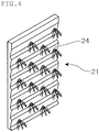
- irregularities formed by combining inclined surfaces as shown in Fig. 4 may be provided such that a liquid fertilizer that flows down along these inclined surfaces can reach efficiently every part of the roots of the seedlings p that are transplanted.
- the liquid fertilizer supply pipe 25 that supplies a liquid fertilizer to the liquid fertilizer supply surface 24 of the culture panel 21 is arranged at each stage, and the guide rail 26 that supports the culture panel 21 can be formed in the shape of a gutter that receives a liquid fertilizer that runs down along the liquid fertilizer supply surface 24 of the culture panel 21.
- the liquid fertilizer received by the guide rail 26 that is formed in the shape of a gutter can be appropriately prepared and circulated to the liquid fertilizer supply pipe 25 and re-used.
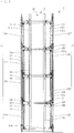
- the hydroponic unit 2 comprises culture blocks 20 in which plural culture panels 21 are supported in a laterally-slidable way by the guide rail 26, and is configured as an assembly of the culture blocks 20 that is formed vertically in a stepwise manner. Then, as shown in Fig. 2 , for each culture block 20, the culture panel 21 laterally slide (in the example shown in Fig. 2 , laterally slide from the left to the right side) in accordance with the growth of the culture object P, and the culture panel 21 in which the culture object P is ready to be harvested is removed, and the culture panels 21 into which new seedlings are transplanted are supported by the guide rail 26. By repeating this operation, the culture object P can be harvested periodically.
- Fig. 6 is an explanatory view showing the manner of the replacement of the culture panels 21.
- a hydroponic unit 2 two hydroponic units 2 are arranged in pair such that the culture surfaces 23 of the culture panel 21 are opposed to each other. Between these paired two hydroponic units 2, a light-collecting apparatus 3 is provided to irradiate the seedlings p that are transplanted into the culture panel 21 of these hydroponic units 2 with natural light taken from the outside.
- the two hydroponic units 2 that are arranged such that the culture surfaces 23 of the culture panels 21 are opposed to each other and the light-collecting apparatus 3 provided therebetween are provided as a constitutional unit, and the liquid fertilizer supply surface 24 of the culture panel 21 of the hydroponic unit 2 are faced with each other, whereby a plurality of these constitutional units can be arranged side by side.
- the light-collecting apparatus 3 is provided with a pair of reflecting plate 31a that are vertically arranged in parallel with the culture surface 23 of the culture panel 21 provided in each hydroponic unit 2.
- the opposing surfaces of each pair of reflecting plates 31a are allowed to be a reflection surface of which the reflectance is enhanced. As a result, natural light taken from a light-collecting opening 30 provided above propagates downward while repeating reflection between the opposing reflection plates 31a.
- the reflection plate 31a is fixed to a support column 35 provided vertically on the frame and a beam 36 intersecting with the support column 35 and assembled in a lattice shape.
- the reflecting plate 31a it is possible to use a metal plate such as a steel plate, an aluminum plate, an aluminum alloy plate in which a layer composed of silver, a silver alloy, aluminum, a multi-layer film or the like are formed on the surface which serves as a reflectance surface in order to have an enhanced reflectance.
- a metal plate such as a steel plate, an aluminum plate, an aluminum alloy plate in which a layer composed of silver, a silver alloy, aluminum, a multi-layer film or the like are formed on the surface which serves as a reflectance surface in order to have an enhanced reflectance.
- the reflecting plate 31a may be formed of a single metal plate or may be formed by combining a plurality of the metal plates.
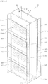
- each reflecting plate 31a a plurality of light-exiting holes 32 are bored at a predetermined opening ratio according to the position of the culture panel 21 (see FIG. 5 ).
- the natural light taken from the light-collecting opening 30 propagates while repeatedly reflected by opposing reflecting surfaces of a reflecting plates 31a, the seedlings p that are transplanted into the culture panel 21 are irradiated with the light through the light-exiting hole 32 bored in the reflecting plate 31a in a spotwise manner.
- Fig. 5 is an explanatory and schematic perspective view of the hydroponic system according to the present embodiment, and shows only main constitutional elements excluding a frame or the like.
- the height of the light-collecting apparatus 3 is equal to or higher than the height of the hydroponic unit 2 in order to allow the seedlings p that are transplanted into the culture panel 21 that are vertically arranged to be irradiated with natural light that is taken from the light-collecting opening 30.
- the light reflecting plate 31a can be divided such that the divided panels can correspond to one or two or more culture panels 21 arranged laterally.
- the light-collecting apparatus 3 has, on its bottom side, a bottom part reflecting plate 31b that reflects light which propagates within the light-collecting apparatus 3 and reaches the bottom surface side towards the light reflecting plate 31a. It is preferred that the bottom side reflection plate 31b be formed in a mountain-like shape with a prescribed apex angle by using the same metal plate as that used for the reflecting plate 31a such that the light which reaches the bottom side is uniformly reflected towards each of the opposing reflecting plates 31a.
- the light-collecting apparatus 3 have a side part reflecting plate 31c to prevent leakage of light from the side.
- the side part reflecting plate 31c also can be formed by using the same metal plate as that used for the reflecting plate 31a.
- a side surrounding member that surrounds the space be provided on the side part of a space between the light-collecting apparatus 3 and the hydroponic unit 2 (culture space).
- a side surrounding member that surrounds the space may be provided on the side part of a space between the light-collecting apparatus 3 and the hydroponic unit 2 (culture space).
- a reflecting side plate 31d of which the surface faces the space may be arranged in parallel with the side part reflecting plate 31c of the light-collecting apparatus 3.
- the side part reflecting plate 31c may be extended to the hydroponic unit 2 side. In the latter case, since the number of members constituting the hydroponic system 1 is not increased, it is advantageous in respect of management of members or production cost.
- the surface of the reflecting plate 31a facing the culture panel 21 be a reflecting surface.
- a reflecting surface is preferably a diffused reflecting surface.
- the culture area can be widened and the amount of harvest can be increased.
- the light-collecting apparatus 3 having a pair of reflecting plates 31a that is vertically arranged in parallel with the culture surface 23 of the culture panel 21, during the process in which the natural light taken from the light-collecting opening propagates while repeatedly being reflected by the reflecting surface of the reflecting plate 31a, by allowing the seedlings p transplanted to the culture panel 21 to be irradiated with light emitted from the light-exiting hole 32 bored in the reflecting plate 31a, the culture object P can be efficiently grown at a low cost and at a high culture density.
- the light-collecting apparatus 3 is configured as a vertical light-collecting apparatus having a pair of reflecting plates 31a that are vertically provided in parallel with the culture surface 23 of the culture panel 21. Since the light-collecting opening can be provided on the top of a building, freedom in installation with respect to the position of the sun is high.
- the light-collecting apparatus When the light-collecting apparatus is configured such that the reflecting plate is arranged laterally, if the light-collecting opening is provided on the top of the building, an additional light-guiding means for guiding light becomes necessary, whereby the structure of a system becomes complicated. Further, if the light-collecting opening is provided on the wall surface of a building, no such light-guiding means becomes necessary. However, according to the position of the sun, there may be a certain period of time during which light collection cannot be conducted.
- the culture object P in addition to vertical provision of the culture panel 21, by configuring a system by the light-collecting apparatus 3 having a pair of reflecting plates 31a that are vertically provided in parallel with the culture surface 23 of the culture panel 21, the culture object P can be efficiently grown with a simple system configuration at a low cost and at a high culture density.
- each of the pair of reflecting plates 31a that are vertically provided in parallel with the culture surface 23 of the culture panel 21 provided in the hydroponic unit 2 are movable from an approaching position to a leaving position relatvie to the hydroponic unit 2.
- Fig. 7 shows the state in which the reflecting plate 31a is at an approaching position relative to the hydroponic unit 2
- the example shown in Fig. 8 shows a state in which one of the reflecting plate 31a is at a leaving position relative to the hydroponic unit 2.
- the reflecting plate 31a is fixed to a support column 35 vertically provided on a carriage 34 moving on the rail 33, and a beam 36 intersecting with the support column 35 and assembled in a lattice pattern, and is movable from the approaching position to the leaving position relative to the hydroponic culture unit 2.
- a support member 37 that vertically protrudes towards the hydroponic unit 2 is fixed on the upper end side of the reflecting plate 31a, and the support member 37 is slidably supported by a guiding member 38 that is fixed to the frame.
- the reflecting plate 31a By leaving the reflecting plate 31a from the hydroponic unit 2, a working space for maintenance of the hydroponic unit 2 can be ensured. Further, in order to prevent the culture object that has grown from contacting the reflecting plate 31a, in accordance with the growth of the culture object P, the reflecting plate 31a can be gradually left from the culture object P, while preventing an amount of light irradiated on the culture object P from decreasing as much as possible. Further, if the distance between the hydroponic unit 2 and the reflecting plate 31a is narrow, air stagnates therebetween, and as a result, occurrence of disadvantages is concerned that carbon dioxide required for the growth of the culture object P becomes insufficient or temperature becomes ununiform. In order to suppress occurrence of such a disadvantage, according to need, by leaving the reflecting plate 31a from the hydroponic unit 2 to secure a prescribed space, ventilation is improved to accelerate the circulation of air.
- the bottom part reflecting plate 31b be formed by combining the same metal plates as those used in the reflecting plate 31a in a mountain-like shape with a prescribed apex angle such that it can be bent at the top.
- move of the reflecting plate 31a be not prevented by allowing the top of the bottom part reflecting plate 31b to rise up while bending (see Fig. 8 ).
- one or both side part reflecting plate(s) 31c be openable and closable in the form of a sliding door or a hinged door.
- the present embodiment differs from the first embodiment in the above-mentioned points, and since other configurations are the same as those of the first
- the culture object P can be efficiently grown at a low cost and at a high culture density by irradiating the culture object P with natural light that is taken from the outside.
- an artificial light source such as a fluorescent lamp, a light-emitting diode and an organic EL can be auxiliarily used in combination.
- a sunlight tracking device In the light-collecting apparatus 3 that receives natural light from the outside and irradiates the culture object P with the natural light, in order to improve the amount of light collected, a sunlight tracking device, a condensing lens, etc. may be provided.
- the present invention is used as a hydroponic system that grows the culture object efficiently at a high culture density at plant factories.
Landscapes
- Life Sciences & Earth Sciences (AREA)
- Environmental Sciences (AREA)
- Hydroponics (AREA)
- Greenhouses (AREA)
- Cultivation Receptacles Or Flower-Pots, Or Pots For Seedlings (AREA)
Claims (7)
- Hydroponisches System (1), das mit einer hydroponischen Einheit (2) versehen ist, in der Kulturplatten (21), in die Setzlinge (p) als Kulturobjekt (P) verpflanzt werden, vertikal angeordnet sind, und
eine Lichtsammelvorrichtung (3), die natürliches Licht von aussen empfängt und die die in die Kulturplatte (21) verpflanzten Setzlinge (p) mit dem natürlichen Licht bestrahlt, dadurch gekennzeichnet, dass
die Lichtsammelvorrichtung (3) ein Paar reflektierende Platten (31a) aufweist, die vertikal parallel zu einer Kulturfläche (23) der in der hydroponischen Einheit (2) vorgesehenen Kulturplatte (21) angeordnet sind, und
die in die Kulturplatte (21) verpflanzten Setzlinge (p) durch eine Vielzahl von in die reflektierenden Platten (31a) gebohrten Lichtaustrittslöchern (32) mit dem natürlichen Licht bestrahlt werden, wobei sich das aus einer Lichtsammelöffnung (30) entnommene natürliche Licht ausbreitet, während es wiederholt von gegenüberliegenden reflektierenden Oberflächen der reflektierenden Platten (31a) reflektiert wird. - Hydroponisches System (1) nach Anspruch 1, wobei auf einem Seitenteil eines Raumes zwischen der Lichtsammelvorrichtung (3) und der hydroponischen Einheit (2) ein das Seitenteil umgebendes Element (31d) vorgesehen ist, welches den Raum umgibt.
- Hydroponisches System (1) nach Anspruch 1 oder 2, wobei eine der Kulturplatte (21) zugewandte Oberfläche der reflektierenden Platten (31a) eine reflektierende Oberfläche ist.
- Hydroponisches System (1) nach irgendeinem der Ansprüche 1 bis 3, wobei die hydroponische Einheit (2) Kulturblöcke (20) umfasst, in denen eine Vielzahl der Kulturplatten (21) durch eine Führungsschiene (26) seitlich verschiebbar getragen sind.
- Hydroponisches System (1) nach Anspruch 4, wobei die hydroponische Einheit (2) als eine Baugruppe der vertikal stufenförmig ausgebildeten Kulturblöcke (20) ausgebildet ist.
- Hydroponisches System (1) nach irgendeinem einem der Ansprüche 1 bis 5, wobei jede der reflektierenden Platten (31a) aus einer annähernden Position in eine sich entfernende Position relativ zur hydroponischen Einheit (2) bewegbar ist.
- Hydroponisches System (1) nach Anspruch 6, wobei die Lichtsammelvorrichtung (3) eine bodenseitige reflektierende Platte (31b) aufweist, die Licht reflektiert, das sich im Inneren der Lichtsammelvorrichtung (3) ausbreitet und den Boden der Lichtsammelvorrichtung (3) in Richtung der reflektierenden Platte (31a) erreicht, und
die bodenseitige reflektierende Platte (31b) in einer gebirgsähnlichen Form mit einem vorgeschriebenen Scheitelwinkel ausgebildet ist, so dass sie an ihrer Oberseite gebogen werden kann, und die Oberseite der bodenseitigen reflektierenden Platte (31b) sich beim Biegen nach oben erhebt, wenn mindestens eine der reflektierenden Platten (31b) sich von der Kulturplatte (21) entfernt.
Applications Claiming Priority (2)
| Application Number | Priority Date | Filing Date | Title |
|---|---|---|---|
| JP2014224934A JP6467872B2 (ja) | 2014-11-05 | 2014-11-05 | 水耕栽培システム |
| PCT/JP2015/004922 WO2016072042A1 (ja) | 2014-11-05 | 2015-09-29 | 水耕栽培システム |
Publications (3)
| Publication Number | Publication Date |
|---|---|
| EP3216342A1 EP3216342A1 (de) | 2017-09-13 |
| EP3216342A4 EP3216342A4 (de) | 2018-06-06 |
| EP3216342B1 true EP3216342B1 (de) | 2020-06-24 |
Family
ID=55908790
Family Applications (1)
| Application Number | Title | Priority Date | Filing Date |
|---|---|---|---|
| EP15856953.3A Active EP3216342B1 (de) | 2014-11-05 | 2015-09-29 | Hydroponisches system |
Country Status (8)
| Country | Link |
|---|---|
| US (1) | US10412908B2 (de) |
| EP (1) | EP3216342B1 (de) |
| JP (1) | JP6467872B2 (de) |
| CN (1) | CN107072157B (de) |
| MY (1) | MY186488A (de) |
| PH (1) | PH12017500657A1 (de) |
| SG (1) | SG11201703236XA (de) |
| WO (1) | WO2016072042A1 (de) |
Cited By (1)
| Publication number | Priority date | Publication date | Assignee | Title |
|---|---|---|---|---|
| US11877548B2 (en) | 2020-09-24 | 2024-01-23 | Cyclofields Indoor Farming | Closed loop vertical disengageable aeroponic growing system |
Families Citing this family (21)
| Publication number | Priority date | Publication date | Assignee | Title |
|---|---|---|---|---|
| EP3119185A4 (de) * | 2014-03-18 | 2017-11-22 | Bax, Heath William | Fallrohranordnung |
| JP6862682B2 (ja) * | 2016-05-30 | 2021-04-21 | 東洋製罐グループホールディングス株式会社 | 水耕栽培システム、水耕栽培制御装置、水耕栽培方法及びプログラム |
| US10863679B2 (en) * | 2016-09-08 | 2020-12-15 | Fork Farms Holdings, Llc | Modular plant growth apparatus |
| CH713118A1 (de) * | 2016-11-10 | 2018-05-15 | Erika Glesser Lott | Gewächshaus mit Lichtumlenkvorrichtung. |
| USD886332S1 (en) * | 2017-01-30 | 2020-06-02 | Metal Sales & Service, Inc. | Architectural wall cladding |
| JP7080013B2 (ja) * | 2017-02-28 | 2022-06-03 | 東洋鋼鈑株式会社 | 水耕栽培システム及び水耕栽培方法 |
| US10660282B1 (en) * | 2017-04-08 | 2020-05-26 | Taylor MichaelMason Parrish | Horticulture apparatus and method |
| US20180325039A1 (en) * | 2017-05-15 | 2018-11-15 | Mark Munro Davison | Device for vertical cultivation of plants and method thereof |
| DK3409103T3 (da) * | 2017-05-30 | 2021-10-25 | Fraunhofer Ges Forschung | Anordning og fremgangsmåde til fremme af planters vækst |
| US12284954B2 (en) | 2017-05-30 | 2025-04-29 | Fraunhofer-Gesellschaft Zur Foerderung Der Angewandten Forschung E.V. | Device for promoting the growth of plants |
| EP3657934A4 (de) * | 2017-07-28 | 2021-05-19 | Biophilia Australia Pty Ltd | Bewegbares lüftungssystem |
| JP6488052B1 (ja) * | 2018-07-19 | 2019-03-20 | 藤澤建機株式会社 | 栽培方法、栽培設備、及び栽培装置 |
| FR3094232B1 (fr) | 2018-10-23 | 2023-09-29 | Capsum | Unite de fabrication d’un extrait d’interet d’au moins un vegetal, microorganisme et/ou champignon |
| US11730090B2 (en) * | 2019-02-25 | 2023-08-22 | Freight Farms, Inc. | Closed farm system with air flow control |
| USD906164S1 (en) * | 2019-08-07 | 2020-12-29 | Conrad Simard | Plant growing table |
| US11707027B2 (en) | 2019-12-02 | 2023-07-25 | Fork Farms Holdings, Llc | Hydroponic grow assembly |
| US20230025874A1 (en) * | 2019-12-20 | 2023-01-26 | 2327100 Alberta Inc. | Modular plant growth system |
| FR3120493B1 (fr) * | 2021-03-15 | 2023-05-05 | Vert Tical Nord | Support de culture modulaire pour paroi végétalisée favorisant le ruissèlement |
| AU2021479214A1 (en) * | 2021-12-17 | 2024-07-18 | CHIA, Bee Hua | An aquaponic system and a method of arranging beds of a plurality of frames of the aquaponic system |
| CN114793873A (zh) * | 2022-05-10 | 2022-07-29 | 内蒙古罗欧农业有限公司 | 一种马铃薯雾培结构和雾培设备 |
| FR3145288A1 (fr) | 2023-01-31 | 2024-08-02 | Capsum | Procédé d’extraction d’un extrait d’intérêt d’au moins un végétal et/ou champignon |
Family Cites Families (14)
| Publication number | Priority date | Publication date | Assignee | Title |
|---|---|---|---|---|
| CN1088383A (zh) | 1992-12-21 | 1994-06-29 | 陈少勇 | 柜式阶梯伸缩型生产机 |
| JPH08331991A (ja) * | 1995-06-07 | 1996-12-17 | Q P Corp | 植物栽培装置 |
| JPH0998665A (ja) * | 1995-07-28 | 1997-04-15 | Mitsubishi Chem Corp | 植物栽培装置 |
| US6000173A (en) * | 1998-08-05 | 1999-12-14 | Schow; Matthew Alan | Hydroponic growing station with intermittent nutrient supply |
| JP4148575B2 (ja) * | 1998-11-02 | 2008-09-10 | 株式会社日建設計 | 光ダクト装置 |
| EP1210868A1 (de) | 1999-01-27 | 2002-06-05 | Seiichi Marumoto | Senkrechtes hydroponisches sprühsystem mit ultrahochdichtungsanlage und zuchtplatte |
| JP2000217451A (ja) * | 1999-02-02 | 2000-08-08 | Kannax:Kk | 水耕栽培装置 |
| JP2004097172A (ja) * | 2002-09-13 | 2004-04-02 | Nikken Sekkei Ltd | 光ダクトを利用した植物育成工場 |
| KR101240249B1 (ko) * | 2011-02-17 | 2013-03-07 | 박영환 | 식물재배시스템 |
| JP5938653B2 (ja) * | 2012-05-11 | 2016-06-22 | パナソニックIpマネジメント株式会社 | 害虫防除照明システム |
| US20140144079A1 (en) * | 2012-11-28 | 2014-05-29 | Ming-Tsun LIN | Plant culturing equipment |
| CN203136711U (zh) | 2013-03-28 | 2013-08-21 | 王雅婧 | 全自动循环旱地无土立体种植装置 |
| WO2015188177A2 (en) * | 2014-06-06 | 2015-12-10 | RackREIT, LLC | System and method for cultivating plants |
| US11089740B2 (en) * | 2015-05-26 | 2021-08-17 | Delos Living Llc | Green wall modular system |
-
2014
- 2014-11-05 JP JP2014224934A patent/JP6467872B2/ja active Active
-
2015
- 2015-09-29 WO PCT/JP2015/004922 patent/WO2016072042A1/ja not_active Ceased
- 2015-09-29 SG SG11201703236XA patent/SG11201703236XA/en unknown
- 2015-09-29 US US15/524,302 patent/US10412908B2/en not_active Expired - Fee Related
- 2015-09-29 MY MYPI2017701411A patent/MY186488A/en unknown
- 2015-09-29 CN CN201580056154.5A patent/CN107072157B/zh not_active Expired - Fee Related
- 2015-09-29 EP EP15856953.3A patent/EP3216342B1/de active Active
-
2017
- 2017-04-07 PH PH12017500657A patent/PH12017500657A1/en unknown
Non-Patent Citations (1)
| Title |
|---|
| None * |
Cited By (1)
| Publication number | Priority date | Publication date | Assignee | Title |
|---|---|---|---|---|
| US11877548B2 (en) | 2020-09-24 | 2024-01-23 | Cyclofields Indoor Farming | Closed loop vertical disengageable aeroponic growing system |
Also Published As
| Publication number | Publication date |
|---|---|
| US10412908B2 (en) | 2019-09-17 |
| CN107072157A (zh) | 2017-08-18 |
| EP3216342A4 (de) | 2018-06-06 |
| JP6467872B2 (ja) | 2019-02-13 |
| WO2016072042A1 (ja) | 2016-05-12 |
| EP3216342A1 (de) | 2017-09-13 |
| CN107072157B (zh) | 2020-11-06 |
| SG11201703236XA (en) | 2017-05-30 |
| PH12017500657A1 (en) | 2017-10-02 |
| JP2016086734A (ja) | 2016-05-23 |
| US20170311560A1 (en) | 2017-11-02 |
| MY186488A (en) | 2021-07-22 |
Similar Documents
| Publication | Publication Date | Title |
|---|---|---|
| US10412908B2 (en) | Hydroponic system | |
| KR102642440B1 (ko) | 수직 농장을 관리하기 위한 자동 모듈식 시스템 | |
| US11178824B2 (en) | System and method for cultivating plants | |
| KR101240249B1 (ko) | 식물재배시스템 | |
| KR101022025B1 (ko) | 식물 재배 장치 | |
| US12507647B2 (en) | Method for growing agricultural products in closed environments comprising a plurality of air conditioned rooms | |
| JP6758731B2 (ja) | 植物又は菌類の生育装置および生育方法 | |
| KR101183817B1 (ko) | 부력판을 이용한 수경재배장치 | |
| JP2018527023A (ja) | 高密度園芸栽培システム、方法および装置 | |
| CN101647386A (zh) | 植物立体栽培塔 | |
| US20200236865A1 (en) | Structure for growing and moving agricultural products farms | |
| WO2014185816A1 (ru) | Солнечный био-вегетарий | |
| US10772262B2 (en) | Facilities and method for cultivating plants | |
| JP5330162B2 (ja) | 閉鎖型植物工場 | |
| JP2001095404A (ja) | 植物の自動化栽培方法及び自動化栽培装置 | |
| KR100921605B1 (ko) | 재배효율을 향상시킨 수평형 작물 재배장치 | |
| WO2015162466A1 (en) | Device for growing plants | |
| KR100939898B1 (ko) | 재배효율을 향상시킨 수직형 작물 재배장치 | |
| KR20200106792A (ko) | 컨테이너 형태의 수직형 식물 수경재배 시스템 | |
| KR101454747B1 (ko) | 다단 작물 재배장치 | |
| JP7687654B2 (ja) | 植物栽培装置 | |
| EP4248736A1 (de) | Automatisiertes system für aeroponische kultivierung in künstlich gesteuerten umgebungen mit vertikal ausgerichteten pflanzenzuchtträgern | |
| KR20190002878U (ko) | 식물 재배대 | |
| JPH0551251B2 (de) | ||
| KR20240160929A (ko) | 계단식 수경재배장치 |
Legal Events
| Date | Code | Title | Description |
|---|---|---|---|
| STAA | Information on the status of an ep patent application or granted ep patent |
Free format text: STATUS: THE INTERNATIONAL PUBLICATION HAS BEEN MADE |
|
| PUAI | Public reference made under article 153(3) epc to a published international application that has entered the european phase |
Free format text: ORIGINAL CODE: 0009012 |
|
| STAA | Information on the status of an ep patent application or granted ep patent |
Free format text: STATUS: REQUEST FOR EXAMINATION WAS MADE |
|
| 17P | Request for examination filed |
Effective date: 20170410 |
|
| AK | Designated contracting states |
Kind code of ref document: A1 Designated state(s): AL AT BE BG CH CY CZ DE DK EE ES FI FR GB GR HR HU IE IS IT LI LT LU LV MC MK MT NL NO PL PT RO RS SE SI SK SM TR |
|
| AX | Request for extension of the european patent |
Extension state: BA ME |
|
| DAV | Request for validation of the european patent (deleted) | ||
| DAX | Request for extension of the european patent (deleted) | ||
| REG | Reference to a national code |
Ref country code: DE Ref legal event code: R079 Ref document number: 602015054867 Country of ref document: DE Free format text: PREVIOUS MAIN CLASS: A01G0031000000 Ipc: A01G0031020000 |
|
| A4 | Supplementary search report drawn up and despatched |
Effective date: 20180507 |
|
| RIC1 | Information provided on ipc code assigned before grant |
Ipc: A01G 31/02 20060101AFI20180430BHEP Ipc: A01G 9/02 20060101ALI20180430BHEP |
|
| GRAP | Despatch of communication of intention to grant a patent |
Free format text: ORIGINAL CODE: EPIDOSNIGR1 |
|
| STAA | Information on the status of an ep patent application or granted ep patent |
Free format text: STATUS: GRANT OF PATENT IS INTENDED |
|
| INTG | Intention to grant announced |
Effective date: 20200121 |
|
| RIN1 | Information on inventor provided before grant (corrected) |
Inventor name: KAMIYA, TAKAHIRO Inventor name: FUJIWARA, AKIHIKO Inventor name: MURAMOTO, KATSUHIRO Inventor name: MURAI, KUNIO Inventor name: ITOH, AKANE Inventor name: KUBO, SHINJI Inventor name: NISHI, MARI Inventor name: MATSUMOTO, SHINICHIROU Inventor name: AGARI, JUN Inventor name: YOSHIMURA, KAZUTO |
|
| GRAS | Grant fee paid |
Free format text: ORIGINAL CODE: EPIDOSNIGR3 |
|
| GRAA | (expected) grant |
Free format text: ORIGINAL CODE: 0009210 |
|
| STAA | Information on the status of an ep patent application or granted ep patent |
Free format text: STATUS: THE PATENT HAS BEEN GRANTED |
|
| AK | Designated contracting states |
Kind code of ref document: B1 Designated state(s): AL AT BE BG CH CY CZ DE DK EE ES FI FR GB GR HR HU IE IS IT LI LT LU LV MC MK MT NL NO PL PT RO RS SE SI SK SM TR |
|
| REG | Reference to a national code |
Ref country code: GB Ref legal event code: FG4D |
|
| REG | Reference to a national code |
Ref country code: CH Ref legal event code: EP |
|
| REG | Reference to a national code |
Ref country code: DE Ref legal event code: R096 Ref document number: 602015054867 Country of ref document: DE |
|
| REG | Reference to a national code |
Ref country code: AT Ref legal event code: REF Ref document number: 1282956 Country of ref document: AT Kind code of ref document: T Effective date: 20200715 |
|
| REG | Reference to a national code |
Ref country code: IE Ref legal event code: FG4D |
|
| REG | Reference to a national code |
Ref country code: NL Ref legal event code: FP |
|
| REG | Reference to a national code |
Ref country code: SE Ref legal event code: TRGR |
|
| PG25 | Lapsed in a contracting state [announced via postgrant information from national office to epo] |
Ref country code: LT Free format text: LAPSE BECAUSE OF FAILURE TO SUBMIT A TRANSLATION OF THE DESCRIPTION OR TO PAY THE FEE WITHIN THE PRESCRIBED TIME-LIMIT Effective date: 20200624 Ref country code: NO Free format text: LAPSE BECAUSE OF FAILURE TO SUBMIT A TRANSLATION OF THE DESCRIPTION OR TO PAY THE FEE WITHIN THE PRESCRIBED TIME-LIMIT Effective date: 20200924 Ref country code: GR Free format text: LAPSE BECAUSE OF FAILURE TO SUBMIT A TRANSLATION OF THE DESCRIPTION OR TO PAY THE FEE WITHIN THE PRESCRIBED TIME-LIMIT Effective date: 20200925 Ref country code: FI Free format text: LAPSE BECAUSE OF FAILURE TO SUBMIT A TRANSLATION OF THE DESCRIPTION OR TO PAY THE FEE WITHIN THE PRESCRIBED TIME-LIMIT Effective date: 20200624 |
|
| REG | Reference to a national code |
Ref country code: LT Ref legal event code: MG4D |
|
| PG25 | Lapsed in a contracting state [announced via postgrant information from national office to epo] |
Ref country code: LV Free format text: LAPSE BECAUSE OF FAILURE TO SUBMIT A TRANSLATION OF THE DESCRIPTION OR TO PAY THE FEE WITHIN THE PRESCRIBED TIME-LIMIT Effective date: 20200624 Ref country code: HR Free format text: LAPSE BECAUSE OF FAILURE TO SUBMIT A TRANSLATION OF THE DESCRIPTION OR TO PAY THE FEE WITHIN THE PRESCRIBED TIME-LIMIT Effective date: 20200624 Ref country code: RS Free format text: LAPSE BECAUSE OF FAILURE TO SUBMIT A TRANSLATION OF THE DESCRIPTION OR TO PAY THE FEE WITHIN THE PRESCRIBED TIME-LIMIT Effective date: 20200624 Ref country code: BG Free format text: LAPSE BECAUSE OF FAILURE TO SUBMIT A TRANSLATION OF THE DESCRIPTION OR TO PAY THE FEE WITHIN THE PRESCRIBED TIME-LIMIT Effective date: 20200924 |
|
| REG | Reference to a national code |
Ref country code: AT Ref legal event code: MK05 Ref document number: 1282956 Country of ref document: AT Kind code of ref document: T Effective date: 20200624 |
|
| PG25 | Lapsed in a contracting state [announced via postgrant information from national office to epo] |
Ref country code: AL Free format text: LAPSE BECAUSE OF FAILURE TO SUBMIT A TRANSLATION OF THE DESCRIPTION OR TO PAY THE FEE WITHIN THE PRESCRIBED TIME-LIMIT Effective date: 20200624 |
|
| PG25 | Lapsed in a contracting state [announced via postgrant information from national office to epo] |
Ref country code: RO Free format text: LAPSE BECAUSE OF FAILURE TO SUBMIT A TRANSLATION OF THE DESCRIPTION OR TO PAY THE FEE WITHIN THE PRESCRIBED TIME-LIMIT Effective date: 20200624 Ref country code: IT Free format text: LAPSE BECAUSE OF FAILURE TO SUBMIT A TRANSLATION OF THE DESCRIPTION OR TO PAY THE FEE WITHIN THE PRESCRIBED TIME-LIMIT Effective date: 20200624 Ref country code: CZ Free format text: LAPSE BECAUSE OF FAILURE TO SUBMIT A TRANSLATION OF THE DESCRIPTION OR TO PAY THE FEE WITHIN THE PRESCRIBED TIME-LIMIT Effective date: 20200624 Ref country code: PT Free format text: LAPSE BECAUSE OF FAILURE TO SUBMIT A TRANSLATION OF THE DESCRIPTION OR TO PAY THE FEE WITHIN THE PRESCRIBED TIME-LIMIT Effective date: 20201026 Ref country code: ES Free format text: LAPSE BECAUSE OF FAILURE TO SUBMIT A TRANSLATION OF THE DESCRIPTION OR TO PAY THE FEE WITHIN THE PRESCRIBED TIME-LIMIT Effective date: 20200624 Ref country code: AT Free format text: LAPSE BECAUSE OF FAILURE TO SUBMIT A TRANSLATION OF THE DESCRIPTION OR TO PAY THE FEE WITHIN THE PRESCRIBED TIME-LIMIT Effective date: 20200624 Ref country code: SM Free format text: LAPSE BECAUSE OF FAILURE TO SUBMIT A TRANSLATION OF THE DESCRIPTION OR TO PAY THE FEE WITHIN THE PRESCRIBED TIME-LIMIT Effective date: 20200624 Ref country code: EE Free format text: LAPSE BECAUSE OF FAILURE TO SUBMIT A TRANSLATION OF THE DESCRIPTION OR TO PAY THE FEE WITHIN THE PRESCRIBED TIME-LIMIT Effective date: 20200624 |
|
| PG25 | Lapsed in a contracting state [announced via postgrant information from national office to epo] |
Ref country code: SK Free format text: LAPSE BECAUSE OF FAILURE TO SUBMIT A TRANSLATION OF THE DESCRIPTION OR TO PAY THE FEE WITHIN THE PRESCRIBED TIME-LIMIT Effective date: 20200624 Ref country code: PL Free format text: LAPSE BECAUSE OF FAILURE TO SUBMIT A TRANSLATION OF THE DESCRIPTION OR TO PAY THE FEE WITHIN THE PRESCRIBED TIME-LIMIT Effective date: 20200624 Ref country code: IS Free format text: LAPSE BECAUSE OF FAILURE TO SUBMIT A TRANSLATION OF THE DESCRIPTION OR TO PAY THE FEE WITHIN THE PRESCRIBED TIME-LIMIT Effective date: 20201024 |
|
| REG | Reference to a national code |
Ref country code: DE Ref legal event code: R097 Ref document number: 602015054867 Country of ref document: DE |
|
| REG | Reference to a national code |
Ref country code: DE Ref legal event code: R119 Ref document number: 602015054867 Country of ref document: DE |
|
| PG25 | Lapsed in a contracting state [announced via postgrant information from national office to epo] |
Ref country code: DK Free format text: LAPSE BECAUSE OF FAILURE TO SUBMIT A TRANSLATION OF THE DESCRIPTION OR TO PAY THE FEE WITHIN THE PRESCRIBED TIME-LIMIT Effective date: 20200624 |
|
| PLBE | No opposition filed within time limit |
Free format text: ORIGINAL CODE: 0009261 |
|
| REG | Reference to a national code |
Ref country code: CH Ref legal event code: PL |
|
| STAA | Information on the status of an ep patent application or granted ep patent |
Free format text: STATUS: NO OPPOSITION FILED WITHIN TIME LIMIT |
|
| GBPC | Gb: european patent ceased through non-payment of renewal fee |
Effective date: 20200929 |
|
| 26N | No opposition filed |
Effective date: 20210325 |
|
| REG | Reference to a national code |
Ref country code: BE Ref legal event code: MM Effective date: 20200930 |
|
| PG25 | Lapsed in a contracting state [announced via postgrant information from national office to epo] |
Ref country code: LU Free format text: LAPSE BECAUSE OF NON-PAYMENT OF DUE FEES Effective date: 20200929 |
|
| PG25 | Lapsed in a contracting state [announced via postgrant information from national office to epo] |
Ref country code: FR Free format text: LAPSE BECAUSE OF NON-PAYMENT OF DUE FEES Effective date: 20200930 Ref country code: DE Free format text: LAPSE BECAUSE OF NON-PAYMENT OF DUE FEES Effective date: 20210401 |
|
| PG25 | Lapsed in a contracting state [announced via postgrant information from national office to epo] |
Ref country code: SI Free format text: LAPSE BECAUSE OF FAILURE TO SUBMIT A TRANSLATION OF THE DESCRIPTION OR TO PAY THE FEE WITHIN THE PRESCRIBED TIME-LIMIT Effective date: 20200624 Ref country code: GB Free format text: LAPSE BECAUSE OF NON-PAYMENT OF DUE FEES Effective date: 20200929 Ref country code: IE Free format text: LAPSE BECAUSE OF NON-PAYMENT OF DUE FEES Effective date: 20200929 Ref country code: LI Free format text: LAPSE BECAUSE OF NON-PAYMENT OF DUE FEES Effective date: 20200930 Ref country code: CH Free format text: LAPSE BECAUSE OF NON-PAYMENT OF DUE FEES Effective date: 20200930 Ref country code: BE Free format text: LAPSE BECAUSE OF NON-PAYMENT OF DUE FEES Effective date: 20200930 |
|
| PGFP | Annual fee paid to national office [announced via postgrant information from national office to epo] |
Ref country code: NL Payment date: 20210920 Year of fee payment: 7 |
|
| PGFP | Annual fee paid to national office [announced via postgrant information from national office to epo] |
Ref country code: SE Payment date: 20210920 Year of fee payment: 7 |
|
| PG25 | Lapsed in a contracting state [announced via postgrant information from national office to epo] |
Ref country code: TR Free format text: LAPSE BECAUSE OF FAILURE TO SUBMIT A TRANSLATION OF THE DESCRIPTION OR TO PAY THE FEE WITHIN THE PRESCRIBED TIME-LIMIT Effective date: 20200624 Ref country code: MT Free format text: LAPSE BECAUSE OF FAILURE TO SUBMIT A TRANSLATION OF THE DESCRIPTION OR TO PAY THE FEE WITHIN THE PRESCRIBED TIME-LIMIT Effective date: 20200624 Ref country code: CY Free format text: LAPSE BECAUSE OF FAILURE TO SUBMIT A TRANSLATION OF THE DESCRIPTION OR TO PAY THE FEE WITHIN THE PRESCRIBED TIME-LIMIT Effective date: 20200624 |
|
| PG25 | Lapsed in a contracting state [announced via postgrant information from national office to epo] |
Ref country code: MK Free format text: LAPSE BECAUSE OF FAILURE TO SUBMIT A TRANSLATION OF THE DESCRIPTION OR TO PAY THE FEE WITHIN THE PRESCRIBED TIME-LIMIT Effective date: 20200624 Ref country code: MC Free format text: LAPSE BECAUSE OF FAILURE TO SUBMIT A TRANSLATION OF THE DESCRIPTION OR TO PAY THE FEE WITHIN THE PRESCRIBED TIME-LIMIT Effective date: 20200624 |
|
| REG | Reference to a national code |
Ref country code: SE Ref legal event code: EUG |
|
| REG | Reference to a national code |
Ref country code: NL Ref legal event code: MM Effective date: 20221001 |
|
| PG25 | Lapsed in a contracting state [announced via postgrant information from national office to epo] |
Ref country code: NL Free format text: LAPSE BECAUSE OF NON-PAYMENT OF DUE FEES Effective date: 20221001 |
|
| PG25 | Lapsed in a contracting state [announced via postgrant information from national office to epo] |
Ref country code: SE Free format text: LAPSE BECAUSE OF NON-PAYMENT OF DUE FEES Effective date: 20220930 |