US11877548B2 - Closed loop vertical disengageable aeroponic growing system - Google Patents
Closed loop vertical disengageable aeroponic growing system Download PDFInfo
- Publication number
- US11877548B2 US11877548B2 US17/484,426 US202117484426A US11877548B2 US 11877548 B2 US11877548 B2 US 11877548B2 US 202117484426 A US202117484426 A US 202117484426A US 11877548 B2 US11877548 B2 US 11877548B2
- Authority
- US
- United States
- Prior art keywords
- wall
- articulated
- articulated wall
- growing
- face
- Prior art date
- Legal status (The legal status is an assumption and is not a legal conclusion. Google has not performed a legal analysis and makes no representation as to the accuracy of the status listed.)
- Active, expires
Links
- 235000015097 nutrients Nutrition 0.000 claims abstract description 30
- 238000000034 method Methods 0.000 claims description 21
- XLYOFNOQVPJJNP-UHFFFAOYSA-N water Substances O XLYOFNOQVPJJNP-UHFFFAOYSA-N 0.000 claims description 17
- 230000008569 process Effects 0.000 claims description 15
- 230000012010 growth Effects 0.000 claims description 12
- 238000004140 cleaning Methods 0.000 claims description 4
- 230000008635 plant growth Effects 0.000 claims description 2
- 230000001737 promoting effect Effects 0.000 claims 5
- 238000005507 spraying Methods 0.000 abstract description 22
- 230000002452 interceptive effect Effects 0.000 abstract 1
- 241000196324 Embryophyta Species 0.000 description 48
- 239000000463 material Substances 0.000 description 13
- 230000005059 dormancy Effects 0.000 description 11
- 238000006073 displacement reaction Methods 0.000 description 9
- 230000008901 benefit Effects 0.000 description 8
- 238000005406 washing Methods 0.000 description 8
- 238000010586 diagram Methods 0.000 description 6
- 230000007613 environmental effect Effects 0.000 description 5
- 230000035784 germination Effects 0.000 description 5
- 238000003306 harvesting Methods 0.000 description 5
- 238000012423 maintenance Methods 0.000 description 4
- 230000000712 assembly Effects 0.000 description 3
- 238000000429 assembly Methods 0.000 description 3
- 230000003028 elevating effect Effects 0.000 description 3
- 239000003337 fertilizer Substances 0.000 description 3
- 238000002156 mixing Methods 0.000 description 3
- 238000012986 modification Methods 0.000 description 3
- 230000004048 modification Effects 0.000 description 3
- 238000009966 trimming Methods 0.000 description 3
- 238000009736 wetting Methods 0.000 description 3
- 238000004458 analytical method Methods 0.000 description 2
- 238000001914 filtration Methods 0.000 description 2
- 239000003595 mist Substances 0.000 description 2
- 230000035515 penetration Effects 0.000 description 2
- 238000011012 sanitization Methods 0.000 description 2
- 238000004659 sterilization and disinfection Methods 0.000 description 2
- 238000002054 transplantation Methods 0.000 description 2
- 229920002943 EPDM rubber Polymers 0.000 description 1
- 239000002253 acid Substances 0.000 description 1
- 239000000443 aerosol Substances 0.000 description 1
- 230000001680 brushing effect Effects 0.000 description 1
- 230000008859 change Effects 0.000 description 1
- 230000000295 complement effect Effects 0.000 description 1
- 238000007791 dehumidification Methods 0.000 description 1
- 238000013461 design Methods 0.000 description 1
- 230000000249 desinfective effect Effects 0.000 description 1
- 238000011161 development Methods 0.000 description 1
- 230000018109 developmental process Effects 0.000 description 1
- 201000010099 disease Diseases 0.000 description 1
- 208000037265 diseases, disorders, signs and symptoms Diseases 0.000 description 1
- 238000009826 distribution Methods 0.000 description 1
- 238000001035 drying Methods 0.000 description 1
- 235000013399 edible fruits Nutrition 0.000 description 1
- 230000000694 effects Effects 0.000 description 1
- 238000005265 energy consumption Methods 0.000 description 1
- 238000001125 extrusion Methods 0.000 description 1
- 238000009313 farming Methods 0.000 description 1
- 238000010413 gardening Methods 0.000 description 1
- 230000005484 gravity Effects 0.000 description 1
- 239000003501 hydroponics Substances 0.000 description 1
- 238000007689 inspection Methods 0.000 description 1
- 238000009413 insulation Methods 0.000 description 1
- 238000002955 isolation Methods 0.000 description 1
- 230000007774 longterm Effects 0.000 description 1
- 238000004519 manufacturing process Methods 0.000 description 1
- 239000012528 membrane Substances 0.000 description 1
- 239000011490 mineral wool Substances 0.000 description 1
- 239000000203 mixture Substances 0.000 description 1
- 238000010899 nucleation Methods 0.000 description 1
- 238000010979 pH adjustment Methods 0.000 description 1
- 238000004806 packaging method and process Methods 0.000 description 1
- 230000037039 plant physiology Effects 0.000 description 1
- 229920003023 plastic Polymers 0.000 description 1
- 230000010152 pollination Effects 0.000 description 1
- 229920001084 poly(chloroprene) Polymers 0.000 description 1
- 238000002360 preparation method Methods 0.000 description 1
- 238000012545 processing Methods 0.000 description 1
- 230000009467 reduction Effects 0.000 description 1
- 150000003839 salts Chemical class 0.000 description 1
- 229920006395 saturated elastomer Polymers 0.000 description 1
- 230000035943 smell Effects 0.000 description 1
- 239000002689 soil Substances 0.000 description 1
- 239000007921 spray Substances 0.000 description 1
- 238000010561 standard procedure Methods 0.000 description 1
- 239000000126 substance Substances 0.000 description 1
- 239000000758 substrate Substances 0.000 description 1
- 235000013311 vegetables Nutrition 0.000 description 1
Images


Classifications
-
- A—HUMAN NECESSITIES
- A01—AGRICULTURE; FORESTRY; ANIMAL HUSBANDRY; HUNTING; TRAPPING; FISHING
- A01G—HORTICULTURE; CULTIVATION OF VEGETABLES, FLOWERS, RICE, FRUIT, VINES, HOPS OR SEAWEED; FORESTRY; WATERING
- A01G31/00—Soilless cultivation, e.g. hydroponics
- A01G31/02—Special apparatus therefor
- A01G31/04—Hydroponic culture on conveyors
- A01G31/045—Hydroponic culture on conveyors with containers guided along a rail
-
- A—HUMAN NECESSITIES
- A01—AGRICULTURE; FORESTRY; ANIMAL HUSBANDRY; HUNTING; TRAPPING; FISHING
- A01G—HORTICULTURE; CULTIVATION OF VEGETABLES, FLOWERS, RICE, FRUIT, VINES, HOPS OR SEAWEED; FORESTRY; WATERING
- A01G31/00—Soilless cultivation, e.g. hydroponics
- A01G31/02—Special apparatus therefor
- A01G31/06—Hydroponic culture on racks or in stacked containers
-
- A—HUMAN NECESSITIES
- A01—AGRICULTURE; FORESTRY; ANIMAL HUSBANDRY; HUNTING; TRAPPING; FISHING
- A01G—HORTICULTURE; CULTIVATION OF VEGETABLES, FLOWERS, RICE, FRUIT, VINES, HOPS OR SEAWEED; FORESTRY; WATERING
- A01G31/00—Soilless cultivation, e.g. hydroponics
- A01G31/02—Special apparatus therefor
- A01G31/04—Hydroponic culture on conveyors
- A01G31/042—Hydroponic culture on conveyors with containers travelling on a belt or the like, or conveyed by chains
-
- A—HUMAN NECESSITIES
- A01—AGRICULTURE; FORESTRY; ANIMAL HUSBANDRY; HUNTING; TRAPPING; FISHING
- A01G—HORTICULTURE; CULTIVATION OF VEGETABLES, FLOWERS, RICE, FRUIT, VINES, HOPS OR SEAWEED; FORESTRY; WATERING
- A01G9/00—Cultivation in receptacles, forcing-frames or greenhouses; Edging for beds, lawn or the like
- A01G9/18—Greenhouses for treating plants with carbon dioxide or the like
-
- A—HUMAN NECESSITIES
- A01—AGRICULTURE; FORESTRY; ANIMAL HUSBANDRY; HUNTING; TRAPPING; FISHING
- A01G—HORTICULTURE; CULTIVATION OF VEGETABLES, FLOWERS, RICE, FRUIT, VINES, HOPS OR SEAWEED; FORESTRY; WATERING
- A01G9/00—Cultivation in receptacles, forcing-frames or greenhouses; Edging for beds, lawn or the like
- A01G9/24—Devices or systems for heating, ventilating, regulating temperature, illuminating, or watering, in greenhouses, forcing-frames, or the like
- A01G9/245—Conduits for heating by means of liquids, e.g. used as frame members or for soil heating
-
- A—HUMAN NECESSITIES
- A01—AGRICULTURE; FORESTRY; ANIMAL HUSBANDRY; HUNTING; TRAPPING; FISHING
- A01G—HORTICULTURE; CULTIVATION OF VEGETABLES, FLOWERS, RICE, FRUIT, VINES, HOPS OR SEAWEED; FORESTRY; WATERING
- A01G9/00—Cultivation in receptacles, forcing-frames or greenhouses; Edging for beds, lawn or the like
- A01G9/24—Devices or systems for heating, ventilating, regulating temperature, illuminating, or watering, in greenhouses, forcing-frames, or the like
- A01G9/246—Air-conditioning systems
-
- A—HUMAN NECESSITIES
- A01—AGRICULTURE; FORESTRY; ANIMAL HUSBANDRY; HUNTING; TRAPPING; FISHING
- A01G—HORTICULTURE; CULTIVATION OF VEGETABLES, FLOWERS, RICE, FRUIT, VINES, HOPS OR SEAWEED; FORESTRY; WATERING
- A01G9/00—Cultivation in receptacles, forcing-frames or greenhouses; Edging for beds, lawn or the like
- A01G9/24—Devices or systems for heating, ventilating, regulating temperature, illuminating, or watering, in greenhouses, forcing-frames, or the like
- A01G9/247—Watering arrangements
-
- A—HUMAN NECESSITIES
- A01—AGRICULTURE; FORESTRY; ANIMAL HUSBANDRY; HUNTING; TRAPPING; FISHING
- A01G—HORTICULTURE; CULTIVATION OF VEGETABLES, FLOWERS, RICE, FRUIT, VINES, HOPS OR SEAWEED; FORESTRY; WATERING
- A01G31/00—Soilless cultivation, e.g. hydroponics
- A01G2031/006—Soilless cultivation, e.g. hydroponics with means for recycling the nutritive solution
-
- Y—GENERAL TAGGING OF NEW TECHNOLOGICAL DEVELOPMENTS; GENERAL TAGGING OF CROSS-SECTIONAL TECHNOLOGIES SPANNING OVER SEVERAL SECTIONS OF THE IPC; TECHNICAL SUBJECTS COVERED BY FORMER USPC CROSS-REFERENCE ART COLLECTIONS [XRACs] AND DIGESTS
- Y02—TECHNOLOGIES OR APPLICATIONS FOR MITIGATION OR ADAPTATION AGAINST CLIMATE CHANGE
- Y02A—TECHNOLOGIES FOR ADAPTATION TO CLIMATE CHANGE
- Y02A40/00—Adaptation technologies in agriculture, forestry, livestock or agroalimentary production
- Y02A40/10—Adaptation technologies in agriculture, forestry, livestock or agroalimentary production in agriculture
- Y02A40/25—Greenhouse technology, e.g. cooling systems therefor
-
- Y—GENERAL TAGGING OF NEW TECHNOLOGICAL DEVELOPMENTS; GENERAL TAGGING OF CROSS-SECTIONAL TECHNOLOGIES SPANNING OVER SEVERAL SECTIONS OF THE IPC; TECHNICAL SUBJECTS COVERED BY FORMER USPC CROSS-REFERENCE ART COLLECTIONS [XRACs] AND DIGESTS
- Y02—TECHNOLOGIES OR APPLICATIONS FOR MITIGATION OR ADAPTATION AGAINST CLIMATE CHANGE
- Y02P—CLIMATE CHANGE MITIGATION TECHNOLOGIES IN THE PRODUCTION OR PROCESSING OF GOODS
- Y02P60/00—Technologies relating to agriculture, livestock or agroalimentary industries
- Y02P60/20—Reduction of greenhouse gas [GHG] emissions in agriculture, e.g. CO2
- Y02P60/21—Dinitrogen oxide [N2O], e.g. using aquaponics, hydroponics or efficiency measures
Definitions
- the present subject matter relates to growing systems and, more particularly, to aeroponic growing systems.
- Aeroponics is a development of hydroponic growing methods. Hydroponics is the technique of growing plants in water-based solutions of nutrient salts.
- Aeroponics is defined by the International Society for Soil-less Culture as “A system where roots are continuously or discontinuously in an environment saturated with fine drops (a mist or aerosol) of nutrient solution”. The method requires no substrate and entails growing plants with their roots suspended in a chamber (the root chamber). The roots are periodically atomized with a fine mist or fog of nutrients, a process which uses significantly less water than alternative growing techniques, such as hydroponic methods. Since their inception some 30 years ago, aeroponics has gained much publicity over recent years, and aeroponic techniques have proved very successful for propagation and are widely used in laboratory studies of plant physiology. On the other hand, aeroponic systems still need to prove themselves on an industrial scale.
- an aeroponic growing apparatus comprising a wall, a lighting system and a nutrient delivery system, the wall being provided with a plurality of containers each adapted for carrying at least one plant to grown therein, the containers being adapted for allowing roots of the plant to extend behind the wall whereas an opposed end of the plant can grow outwardly of the wall and is subject to light from the lighting system, the delivery system being adapted to provide nutrients to the roots.
- the wall including a series of articulated panels connected together side-by-side, that can be embodied as a series of wall portions where the front wall portion is connected to the last wall portion forming a chamber therein, extends in a closed loop and is moveable along a path, a chamber being defined inwardly of the wall and housing the nutrient delivery system.
- railings are provided for guiding the wall along the path.
- the railings include top railings, with the upper ends of the panels being respectively engaged to top railings.
- an access entry is provided on the wall so as to allow access to the chamber.
- the flexible joints are substantially opaque for assisting in maintaining darkness in the chamber.
- the containers have different configurations and are adapted to be disposed in various patterns on the wall.
- a motorization assembly is provided for driving the wall and selectively moving the wall along the path.
- the embodiments described herein provide in one aspect an aeroponic growing system comprising a plurality of aeroponic growing apparatuses.
- the aeroponic growing apparatuses are disposed substantially parallelly.
- a service railing system for removing the wall from an aeroponic growing apparatus thereof and for displacing the wall to at least one station.
- the station includes at least one of an inverting station, picking/harvesting station, a sanitizing station, a seeding/transplantation station and a dormancy room.
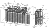
- FIG. 1 is a perspective view of an aeroponic growing apparatus in accordance with an exemplary embodiment
- FIG. 2 is an enlarged perspective view of an upper portion of the aeroponic growing apparatus of FIG. 1 ;
- FIG. 3 is a schematic vertical transversal cross section view of the aeroponic growing apparatus of FIG. 1 ;
- FIG. 4 is an exemplary exploded perspective view of an individual plant-growing container (cup) and of part of a wall of the aeroponic growing apparatus of FIG. 1 , in accordance with another exemplary embodiment;
- FIG. 5 is an exemplary front elevation view of part of a wall of the aeroponic growing apparatus of FIG. 1 and of a number of plant-growing containers mounted thereto, showing various distribution patterns of the plant-growing containers, in accordance with another exemplary embodiment;
- FIG. 6 is a perspective view showing an aeroponic growing system including a series of aeroponic growing apparatuses of FIG. 1 and additional stations, in accordance with another exemplary embodiment
- FIG. 7 is a perspective view of part of additional stations of the aeroponic growing system of FIG. 6 , in accordance with another exemplary embodiment
- FIG. 8 is a side elevation view of part of the aeroponic growing system of FIG. 6 , including end views of three (3) exemplary aeroponic growing apparatuses of FIG. 1 , in accordance with another exemplary embodiment;
- FIG. 9 is a side view of the plant-growing container (cup) of FIG. 4 with a grown plant, wherein the container is mounted to a part of a wall of the aeroponic growing apparatus of FIG. 1 ;
- FIGS. 10 and 11 are respectively an exploded perspective view and a side view of an individual plant-growing container (cup) and of part of a wall of the aeroponic growing apparatus of FIG. 1 , in accordance with another exemplary embodiment;
- FIGS. 12 and 13 are respectively an exploded perspective view and a side view of an individual plant-growing container (cup) and of part of a wall of the aeroponic growing apparatus of FIG. 1 , in accordance with another exemplary embodiment;
- FIG. 14 is a top view of a joint in accordance with an embodiment
- FIGS. 15 A and 15 B are respectively a perspective view of a front top portion and of a rear top portion of a wall with plant-growing containers (cups) mounted thereto in accordance with an embodiment
- FIGS. 16 A and 16 B are respectively a perspective view of a front top portion and of a rear top portion of a wall with integrated plant-growing containers in accordance with an embodiment
- FIGS. 17 and 18 are respectively a perspective view and a floor plan of an aeroponic growing system comprising a plurality of stations designated for distinct phases and/or processes;
- FIG. 19 is a partial perspective view of an aeroponic growing system with the door between the growing area and the workstation open;
- FIG. 20 is a perspective view of the bottom end portion of an aeroponic growing apparatus
- FIG. 21 is an enlarged perspective view of an upper portion of the aeroponic growing apparatus in accordance with an embodiment using the panels of FIGS. 16 A and 16 B ;
- FIG. 22 is a perspective view of an aeroponic growing apparatus in accordance with the exemplary embodiment of FIG. 21 ;
- FIG. 23 is an enlarged perspective view of an upper portion of the aeroponic growing apparatus in accordance with an embodiment with a top portion of the wall travelling along the service railing system toward the workstation;
- FIGS. 24 A to 24 F are perspective views depicting traveling states of the wall during a process of inverting the orientation of the elongated panels
- FIG. 25 is a schematic vertical transversal cross section view of the aeroponic growing apparatus of FIG. 1 with the elongated panels inverted through the process depicted through FIGS. 24 A to 24 F ;
- FIG. 26 is a flow chart illustrating steps involved in growing plants using an embodiment of the aeroponic growing system
- FIG. 27 is a block diagram illustrating components involved in a mixing room adapted to mix fertilizers and nutrients
- FIG. 28 is a flow chart illustrating steps involved in a washing system adapted to wash components of the aeroponic growing system
- FIG. 29 is a block diagram illustrating components involved in controlling environmental conditions of the aeroponic growing system.
- FIG. 30 is a block diagram illustrating modules of the aeroponic growing system.
- FIG. 6 illustrates an aeroponic growing system S, which includes a number of aeroponic growing apparatuses A and additional stations, as described hereinafter.
- the aeroponic growing apparatus A is shown in substantial isolation in FIGS. 1 to 3 .
- the aeroponic growing apparatus A takes the form of a carousel and comprises a moveable articulated wall 1002 that includes a number of vertically elongated panels 1000 , for instance in the form of inert material strips.
- the panels 1000 are pivotally mounted side-by-side to one another along vertical longitudinal edges thereof.
- the elongated panels 1000 are pivotally mounted to each other via flexible and opaque joints 1010 (see FIGS. 2 and 14 ), which are adapted to substantially ensure water tightness and to substantially prevent light from entering the dark environment inside the moving carousel, i.e., the chamber within the articulated wall 1002 .
- the articulated wall 1002 forms a, e.g., closed loop having a general oblong shape (“racetrack” configuration).
- the elongated panels 1000 are made, according to a realization, of white ABS material processed against UV light, such material having the advantage of reflecting a good ratio of light, and a co-extrusion of black plastic which is designed to prevent the light to pass through the wall 1002 and reach the other side of the wall 1002 .
- the flexible and opaque joints 1010 comprises a pair of U-shaped extremities 1070 made of PVC rigid material, typically white PVC, with the edges of the elongated panels 1000 being inserted in the clearance between the two arms of the U-shaped extremities 1070 .
- a flexible body 1072 joins the two extremities 1070 , with the flexibility characteristics of the body 1072 being selected in function of the range of acceptable angles the walls 1002 may undergo when a carousel, or when being displaced from a first aeroponic growing apparatuses A, e.g., in the growing area, to another aeroponic growing apparatuses A, e.g., workstation 1034 , and during other processes as will be discussed hereinafter.
- the flexible body 1072 is made of black PVC.
- the whole flexible and opaque joints 1010 is processed against UV light.
- the whole, or at least the body 1072 is opaque; preventing, as discussed, water and light to travel between the panels 1000 forming the walls 1002 .
- FIGS. 15 A and 15 B it is depicted an elongated panel 1000 having flexible and opaque joints 1010 mounted to its side edges, and inert material cups 1012 mounted to the openings of the elongated panel 1000 . It is further depicted the chain 1044 taking place about the top edge of the elongated panels 1000 and a rail attachment member 1076 extending beyond the top edge and adapted to cooperate with the top railings 1004 .
- FIGS. 16 A and 16 B another realization involves a high-density elongated panel 1000 manufactured with sloped portions adapted to the grown of the plants.
- the sloped portions provide a slightly upwardly orientation for the plants on the stem side and a downwardly sloped surface on the root side wherein the roots may lay down, and providing the slope desired for the appropriate spraying of the nutrients.
- the elongated panels 1000 are thermoformed with the depicted shape.
- FIGS. 21 and 22 depict an embodiment using the high-density elongated panels 1000 of FIGS. 16 A and 16 B , wherein such configuration is well adapted to small plants.
- the aeroponic growing apparatus A also includes variable speed motorization assembly 1024 to selectively drive the articulated wall 1002 when operating as a carousel, e.g., selectively clockwise and anti-clockwise, and top railings 1004 ( FIG. 3 ) for guiding the elongated panels 1000 during the driven displacement of the articulated wall 1002 , the elongated panels 1000 having upper ends thereof engaged respectively in the top railings 1004 .
- variable speed motorization assembly 1024 to selectively drive the articulated wall 1002 when operating as a carousel, e.g., selectively clockwise and anti-clockwise, and top railings 1004 ( FIG. 3 ) for guiding the elongated panels 1000 during the driven displacement of the articulated wall 1002 , the elongated panels 1000 having upper ends thereof engaged respectively in the top railings 1004 .
- driving the articulated walls 1002 allows to selectively change the location of the elongated panels 1000 , and the plants mounted thereto, which permits to better balance the lighting between the plants and thus to optimize the lighting according to the requirements of all the plants.
- driving of the articulated walls 1002 involves the articulated walls 1002 having a driving structure, e.g., a chain 1044 , about the top with the variable speed motorization assembly 1024 comprising a set of engaging devices, e.g., tires 1042 , engaging both sides of the chain 1044 to drive the aeroponic growing apparatus A therethrough.
- the variable speed motorization assembly 1024 comprises a plurality of panel-contacting drive members, embodied in the present situation as four (4) tires 1042 mounted in pairs, driven by the same motor (not identified) and through straps (not identified), wherein each pair of tires 1042 exerts a coordinated displacement of a different panel 1000 with friction to thereby drive the whole wall 1002 .
- the articulated wall 1002 is provided with an access point 1008 for maintenance and inspection of the inside of the carousel or aeroponic growing apparatus A.
- the aeroponic growing apparatus A also includes top covers or shields 1016 , with the top ones seen in FIG. 2 , in order to prevent light from entering the carousel.
- a pan 1018 at the lower end of the aeroponic growing apparatus A to collect residual solutions, e.g., nutrients and water.
- the shields 1016 and pan 1018 comprises brushes comprising a double membrane of EPDM which ensures the system to prevent according to necessary requirements the light from travelling to the other side of the walls 1002 .
- the aeroponic growing system includes a movable platform 1020 , with one such movable platform 1020 being typically positioned at least one end of the aeroponic growing apparatus A for trimming, planting, picking and maintenance purposes of the plants, or other, being grown on the articulated wall 1002 , as will be described in more details hereinafter.
- a movable platform 1020 may be moved at the end for performing operation on the articulated walls 1002 , and may further be moved between ends of aeroponic growing apparatuses A with minimized displacement.
- the aeroponic growing apparatus A and, more particularly, the elongated panels 1000 thereof are each provided with a number of inert material cups 1012 , which are designed for supporting growing plants 1014 , as best seen in FIGS. 2 and 4 .
- Complementary openings 1013 are defined in the elongated panels 1000 such that the cups 1012 are e.g., removably, mounted thereto and to allow the roots of the plants 1014 to extend inwardly of the articulated wall 1002 .
- the inert material cups 1012 have an oblong base.
- the inert material cups 1012 extend outwards and slightly upward, resulting in nutrients sprayed from the opposed (inner) side of the articulated wall 1002 that are not absorbed by the plant to drip over the inner side rather than travelling to the first (external) side of the articulated wall 1002 .
- the slope of the inert material cups 1012 is designed to obtain a balance between applied gravity over the roots and the normal orientation of the plant toward lighting system 1026 (see FIG. 9 ) , preferably a vertical lighting system 1026 lighting the whole height of one or more panels 1000 .
- the inert material cups 1012 has a cylindrical opening an inwardly extending shoulder 1052 .
- a disk 1056 of, e.g., neoprene is inserted in the cylindrical opening, being prevented to slide beyond by the shoulder 1052 .
- the seed 1060 is inserted in a rockwool cylinder providing an appropriate environment for the seed to become a fully grown plant, itself inserted in the compressible disk 1056 .
- the inert material cups 1012 feature semi-circular clearances 1054 on both sides providing space to grip the disk 1056 , thereby easing maintenance.
- the cups 1012 are made of opaque material, and are processed to resist to UV light.
- the compressible disks 1056 are adapted to prevent water and light to travel between the sides of the wall 1002 .
- cooperation of the marrying shapes of the base of the cups 1012 and of the openings in the walls 1002 is designed to maintain orientation of the cups 1012 relative to the vertical and to provide watertightness and light insulation between the sides of the walls 1002 like other components of the aeroponic growing apparatus A.
- FIGS. 12 and 13 other realization may involve other types of compressible disks 1062 adapted to farm plants at other phases than seeds to stem, such as like depicted cuts 1064 planted into the compressible disks 1062 (e.g., for farming of basilic).
- the inert material strips or panels 1000 can adopt various sizes (e.g., widths) as well as different patterns for the openings 1013 thereof, for instance to optimize the number of growing cavities in the articulated wall 1002 .
- interchangeable cups 1012 are fixable and can be of variable shapes and sizes to optimize the growing capacity, for example depending on the plants being grown therein.
- the articulated wall 1002 is adapted to move horizontally in a closed loop around fixed spraying systems 1025 (see FIG. 3 ) mounted inwardly of the articulated wall 1002 , the spraying systems 1025 being adapted to deliver a nutrient solution to the roots of the plants 1014 .
- Driving of the articulated walls 1002 provides a solution to limit the side and direction of the fixed spraying systems 1025 . It further provides a continuous spraying solution, in other words one minimizing the interruptions of the spraying process and thus avoiding most problems of nozzles clogging with nutrients that would occur with intermittent spraying solutions.
- the spraying systems 1025 is movable toward and away of the articulated wall 1002 , wherein controlling pressure and distance allows to control the characteristics of the sprayed droplets of nutrients.
- Transversal rails 1050 may be mounted about the top of the aeroponic growing apparatuses A, perpendicular to the longitudinal directions of the carousels, for components to be suspended to the transversal rails 1050 .
- the lighting system 1026 is attached to the transversal rails 1050 , allowing to increase or decrease clearance between the lighting system 1026 and the carousel by changing location of attachment of the lighting system 1026 to the transversal rails 1050 at the top.
- FIG. 8 depicts the capability through displacement of the suspended lighting system 1026 to set its distance to the side of the carousel.
- the nature, quantity, frequency and other characteristics of the spraying are inter-related to the nature of the plants and to the other parameters of the aeroponic growing system S, such as, e.g., the speed the articulated wall 1002 is driven and the characteristics and number of spraying systems 1025 such as the number and distance between the nozzles, and the location and width of the spraying system(s) 1025 within the carousel.
- a lighting system 1026 is provided exteriorly of each longitudinal side of the articulated wall 1002 for providing better light penetration for the plants 1014 .
- the aeroponic growing apparatus A also includes an outside fixed vertical spraying system 1022 , which is adapted to provide a pollination solution to the plants 1014 in need.
- the aeroponic growing apparatus A provides a dark environment within the moving carousel or articulated wall 1002 where the roots of the plants 1014 can grow without undesirable light penetration.
- the aeroponic growing system S includes an adjustable structural assembly (not identified) that secures the top of the aeroponic growing apparatuses A together to strengthen and stabilise them.
- the aeroponic growing system S also includes a transversal railing system 1030 , which extends perpendicularly to longitudinal axes of the aeroponic growing apparatuses A, so as to enable the structure to be levelled and the distance between the plants 1014 and the lighting systems 1026 to be adjusted, for instance by displacing the aeroponic growing apparatuses A along the railing system 1030 such as to selectively vary the distance between the aeroponic growing apparatuses A. This allows to optimize floor space, room space, growth conditions and to fight the long-term loss of efficiency of the lighting systems 1026 .
- the aeroponic growing system S includes a longitudinal railing system 1032 , which extend parallelly to the longitudinal axes of the aeroponic growing apparatuses A, the railing system 1032 serving to hold the lighting systems 1026 and to move the same longitudinally along the aeroponic growing apparatuses A, for instance to adjust the distance between the lighting systems 1026 and to allow for maintenance.
- the aeroponic growing system S further includes a service railing system 1006 adapted to disengage the articulated wall 1002 from one of the aeroponic growing apparatuses A.
- the articulated wall 1002 is disengageable from its aeroponic growing apparatus A and is then displaced on the service railing system 1006 between different rooms or stations, which stations are used, for instance, for reversing the orientation of the wall 1002 through an inverting station, for picking the sufficiently grown plants, sanitizing, planting, dormancy period, and other purposes.
- a bottom guiding system 1080 comprises wheels 1082 guiding the bottom edge of the articulated wall 1002 in its course and an opening 1084 extending from the straight portion of the pan 1018 parallel to the longitudinal axis of the aeroponic growing apparatus A, wherein the opening 1084 follows the course of the service railing system 1006 on top.
- the aeroponic growing system is adapted to selectively move an articulated wall 1002 to a desired position, e.g., on the desired aeroponic growing apparatus A, to lead an articulated wall 1002 to disengage from an aeroponic growing apparatus A, or for an articulated wall 1002 to be inverted.
- the service railing system 1006 may lead to a workstation 1034 .
- the working station 1034 comprises shields 1016 and a pan 1018 for recuperating water used during e.g., cleaning of the articulated wall 1002 .
- the driving system 1024 further comprises one or more additional motorization assemblies, that may comprise e.g., a set of two opposed tires, to drive the articulated walls 1002 when displaced out of around an aeroponic growing apparatus A. It is worth noting that the one or more motorization assemblies 1024 may be installed over the possible path of the articulated walls 1002 to drive the articulated walls 1002 regardless of their actual position in the potential paths as will be discussed in more details hereinafter. It further provides the advantage of centralizing the automation process, limiting the resources requirements.
- a central, ergonomic workstation 1034 is provided, which is located remotely from the grow room (where are the aeroponic growing apparatuses A).
- the workstation 1034 is associated an elevating movable platform 1039 that is used to work on an articulated wall 1002 that is temporarily disassociated from its original aeroponic growing apparatus A, such as to harvest grown plants, trim growing plants, new plantings, etc.
- the workstation 1034 also reduces manpower, reduces exposure to UV lights and offers an ergonomic working environment.
- the workstation 1034 and the elevating platform 1039 may be operated by an operator, or may in other realization, or for specific operations, be fully automated, wherein e.g., a robotic arm coupled with sensors may perform operations over the articulated walls 1002 according to program codes, or any alternative in-between involving a cooperation of robotic operations and human operations.
- the elevating platform 1039 is adapted to be displaced up and down, so as to allow an operator, and/or the robotic arm, to easily reach each section of the articulated wall 1002 .
- the ability to move the articulated wall 1002 backward and forward through the motorization assembly 1024 allows to easily reach each section thereof.
- the railing system comprising the top railings 1004 and the service railings 1006 , may allow an articulated wall 1002 located on the workstation 1034 , like other aeroponic growing apparatuses A, to be inverted, for e.g., germination phase.
- the aeroponic growing system S also provides for a mechanical feeding system 1036 adapted to feed supplies (packaging, sprouts, etc.) to the operator and/or the automated devices operating the workstation 1034 .
- a mechanical feeding system 1036 adapted to feed supplies (packaging, sprouts, etc.) to the operator and/or the automated devices operating the workstation 1034 .
- Another mechanical system 1038 is provided to take down supplies (finished products, wastes, etc.) to the floor.
- a centralized washing system 1040 which is separated from the grow room and is adapted to wash both sides of the articulated wall 1002 .
- the washing system 1040 typically provides an automated system to wash, rinse and sanitize both sides of articulated wall 1002 , including for instance moving brushes to clean both sides of the wall 1002 .
- the automated washing system 1040 allows for the wall 1002 to be moved backward and forward for cleaning the wall section by section. Such an automated washing system eliminates the dangers of using labor for this task (heights, lighting systems, etc.).
- FIG. 23 a portion of a wall 1002 travelling along the service railing system toward the workstation 1034 , wherein at least some of the elongated panels 1000 have left the carousel configuration.
- the configuration of the service railing system 1006 allows to drive a wall 1002 such as inverting the facing side (e.g., from the cups 1012 facing outward to the cups 1012 facing inward).
- FIG. 24 A shows the wall 1002 as a carousel in its initial configuration, cups 1012 facing outward.
- FIG. 24 B depicts the wall 1002 exiting the first structure and entering the second structure through rails section 1090 .
- FIG. 24 C depicts the last elongated panels 1000 being led around the second structure.
- FIG. 24 D depicts the first elongated panels 1000 leaving the area of the second structure through railing section 1092 .
- FIG. 24 E depicts the elongated panels 1000 beginning to be suspended to the rails of the first structure with the cups 1012 facing inward.
- FIG. 24 F depicts when all the articulated wall 1002 is back around the first structure, with the cups 1012 facing inward. Accordingly, between FIG. 24 A and FIG. 24 F , the orientation of the wall 1002 is inverted.
- this inverted configuration wherein the cups 1012 are facing inward may be advantageous for some phases of the growth of the plants, e.g., during the germination phase.
- the wall 1002 inverted it is possible to have increased relative humidity and temperature conditions without having to set it to the whole room.
- the process of inverting the wall 1002 has further advantages such as avoiding some transplantation phases, adding a solution to control the lighting of the plants e.g., a phase of complete darkness, without them having to be moved to another room/station even when the neighbor carousel is lit, etc. Such advantages and others may be foreseen by a person skilled in the art.
- the aeroponic growing system S may comprise a plurality of stations designated for distinct phases and/or processes, wherein the stations may be in closable spaces connected by the service railing system 1006 .
- the service railing system 1006 may allow to drive articulated walls 1002 between the growing area and the workstation 1034 , and further a dormancy area 1078 divided by a closable door 1074 , wherein the plants may be put into, e.g., a dormancy period free of light and may be returned to the growing area when the dormancy period is done.
- the e.g., dormancy area 1078 may offer one or more characteristics (e.g., temperature, relative humidity, lighting, feeding of nutrients and fertilizers, etc.) that may differ from the growing area.
- closable doors 1074 allow to close all the areas, therefore limiting or preventing processing or environmental control in one area to negatively affect the plants located in another area and avoiding necessity of lighting system(s) 1026 in a dormancy room.
- the dormancy area 1078 Is adapted to house a plurality of articulated walls 1002 , wherein the articulated walls 1002 are designed to be stored as carousels, with each of the articulated walls 1002 being available to be driven out of the dormancy area 1078 independently from the other(s).
- the aeroponic growing system S further includes various sensors and software.
- sensors are provided to monitor critical parameters.
- a software monitors and analyses critical information and suggests or acts with regards to the results.
- the aeroponic growing system S is adapted to measure, analyse, and automatically adjust parameters according to the plant requirements (e.g., light cycle, nutrient preparation, nutrient spraying, quantity of CO 2 , temperature control, relative humidity control, watering, driving speed and direction of carousels, energy consumption, generation of alarms, generation of reports, etc.).
- Software is also provided to control all the displacements of any articulated walls 1002 along the railing system, including for controlling the displacement of the articulated walls 1002 for reversing, picking/harvesting, trimming, planting, washing and other purposes.
- Software also keeps a log wherein is kept track of all information used and/or monitored during the growing process to ensure a traceability.
- the aeroponic growing system S comprises a plurality of aeroponic growing apparatuses A adapted for walls 1002 to be driven as carousels.
- the aeroponic growing apparatuses A are divided between areas and interconnected through a railing system comprising the top railings 1004 and the service railing system 1006 , and a plurality of motorization assemblies 1024 adapted to drive the articulated walls 1002 suspended to the railing system as carousels suspended to the top railings 1004 and as unwrapped articulated walls 1002 suspended to the service railing system 1006 between the aeroponic growing apparatuses A, and/or to invert the articulated walls 1002 .
- Stations or areas may take many functions, comprising for example a planting station, a growing station, a germination station, a harvesting station, a dormancy station and a cleaning station, inter alia.
- Walls 1002 are interconnected with flexible and opaque joints 1010 , and the solution uses components and/or solutions on top and bottom adapted to prevent water and light to travel from one side of the articulated walls 1002 to the other side when configured as a carousel.
- the aeroponic growing system S comprises spraying systems 1025 and lighting systems 1026 to provide nutrients and light to plants growing on the walls 1002 , with the aeroponic growing apparatuses A comprising a pan 1018 at the bottom to recover unabsorbed nutrients.
- the aeroponic growing apparatuses A also comprises guiding means at the bottom to guide displacement of the elongated panels 1000 .
- the aeroponic growing system S may comprise structure adapted to customize operation parameters, such as distance between the nozzles of the spraying systems 1025 and a wall 1002 .
- the elongated panels 1000 are adapted with cups 1012 and other growing means to attach seeds or plants to the aeroponic growing apparatus A and promote growth.
- the aeroponic growing system S comprises environmental control components as explained in relation with the following figures.
- Step 1102 consists in choosing the nature of the planting.
- Step 1104 consists in planting cuts or young plants in the elongated panels 1000 .
- step 1106 consists in planting seeds, followed with step 1108 wherein the wall 1002 are displaced/inverted for a germination period, and step 1010 wherein wall 1002 are displaced/inverted once again after the germination period.
- Step 1112 consists in displacing the wall 1002 to a growing station where light and nutrients may be provided to the plants.
- step 1114 of displacing the walls 1002 to the workstation and step 1116 of trimming the plants may take place numerous times, followed with step 1112 consisting in displacing the wall 1002 to the growing station.
- step 1124 of displacing the wall 1002 to a dormancy room 1078 may take place, followed with the wall 1002 being returned to the growing station at step 1112 .
- Final steps include to displace the wall to workstation 1034 at step 1118 , and harvesting the plants on the wall 1002 at step 1120 , followed with either a return to the growing station (step 1112 ) or step 1122 consisting in washing the wall 1102 , after which the wall 1002 may be displaced back to the growing station (step 1112 ).
- FIG. 27 a block diagram schematically illustrates reservoir(s) of water 1202 , reservoir(s) of fertilizers and nutrients 1204 and reservoir(s) of acid/base product 1206 used for pH adjustments are provided.
- a filtration/disinfection station 1208 is used to process water, and these products are mixed in a mixing tank 1210 to obtain a desired mix.
- These products are fed to reservoirs and controls (e.g., 1212 and 1214 ), and are fed to the fixed spraying systems 1025 as a spraying solution to be used to feed the plants (e.g., 1216 and 1218 ).
- the spraying solution is fed to spray nozzles, e.g., spraying roots growing apparatus 1220 of one or more walls 1002 , with the spraying solution not absorbed being collected through the collecting pan assembly 1222 , pumped from sump pit 1224 , and filtered and/or disinfected 1226 before being returned into e.g., the reservoirs 1216 / 1218 .
- spray nozzles e.g., spraying roots growing apparatus 1220 of one or more walls 1002 .
- process of washing the panels 1000 comprises, for the two sides of the panels 1000 , wetting (step 1304 ), soaping (step 1306 ), brushing (step 1308 ), rinsing (step 1310 ), drying (step 1312 ), and disinfecting (step 1314 ) the panels 1000 using UV light, steam and/or chemicals.
- the process comprises the control of temperature and pressure of water (step 1318 / 1322 ) and the filtration and/or disinfection of water (step 1316 / 1320 ) recovered from the steps of wetting (step 1304 ) and rinsing (step 1310 ).
- a Programmable Logic Controller 1302 controls the displacement of the panels 1000 and processes performed through the steps listed before when automated.
- the block diagram shows components involved in environmental control, comprising heat pumps 1402 , heat exchangers 1404 , 1406 associated with heat pumps 1402 or control of temperature of spraying solutions, warm-water reservoir(s) 1408 and cold-water reservoir(s) 1410 . It also comprises heat exchanger 1412 , blower 1414 and heater 1416 associated with dehumidification and climatization, and CO 2 source 1418 to provide the right controlled environment to the plants to optimize their growth.
- a block diagram depicts the modules participating in the aeroponic growing system S.
- the modules comprise a master PLC 1502 connected to a customer interface 1504 and a remote access 1506 providing access to controls both on-site and remotely.
- a control panel 1508 and a power panel 1510 are dedicated to the control of the mixing room where water and nutrients are mixed.
- the environmental control associated with each room/area are associated a control panel 1512 and 1516 and a power panel 1514 , 1516 .
- Associated with each of the aeroponic growing apparatuses A are associated a control panel 1520 comprising a slave PLC, and a power panel 1522 . All control panels 1508 , 1512 , 1516 and 1520 are connected to the master PLC 1502 for central control of all aspects of the aeroponic growing system S.
- This modular configuration provides scalability to the aeroponic growing system S.
Abstract
Description
Claims (19)
Priority Applications (1)
| Application Number | Priority Date | Filing Date | Title |
|---|---|---|---|
| US17/484,426 US11877548B2 (en) | 2020-09-24 | 2021-09-24 | Closed loop vertical disengageable aeroponic growing system |
Applications Claiming Priority (2)
| Application Number | Priority Date | Filing Date | Title |
|---|---|---|---|
| US202063082488P | 2020-09-24 | 2020-09-24 | |
| US17/484,426 US11877548B2 (en) | 2020-09-24 | 2021-09-24 | Closed loop vertical disengageable aeroponic growing system |
Publications (2)
| Publication Number | Publication Date |
|---|---|
| US20220087123A1 US20220087123A1 (en) | 2022-03-24 |
| US11877548B2 true US11877548B2 (en) | 2024-01-23 |
Family
ID=80739376
Family Applications (1)
| Application Number | Title | Priority Date | Filing Date |
|---|---|---|---|
| US17/484,426 Active 2041-12-11 US11877548B2 (en) | 2020-09-24 | 2021-09-24 | Closed loop vertical disengageable aeroponic growing system |
Country Status (3)
| Country | Link |
|---|---|
| US (1) | US11877548B2 (en) |
| CA (1) | CA3189246A1 (en) |
| WO (1) | WO2022061467A1 (en) |
Families Citing this family (1)
| Publication number | Priority date | Publication date | Assignee | Title |
|---|---|---|---|---|
| DE102022124658A1 (en) * | 2022-09-26 | 2024-03-28 | Storagepackaging Ug (Haftungsbeschränkt) | Device for cultivating and growing plants |
Citations (96)
| Publication number | Priority date | Publication date | Assignee | Title |
|---|---|---|---|---|
| US2244677A (en) | 1937-07-06 | 1941-06-10 | Fay D Cornell | System of plant production |
| US3254447A (en) | 1963-01-04 | 1966-06-07 | Ruthner Othmar | Apparatus for the artificial cultivation of plants, bacteria, and similar organism |
| US4255897A (en) | 1977-05-12 | 1981-03-17 | Othmar Ruthner | Method and apparatus for the improvement of storage of biochemical energy in plants |
| US4356664A (en) * | 1980-12-01 | 1982-11-02 | Othmar Ruthner | Plant for the continuous production of green forage |
| US5511340A (en) | 1987-03-04 | 1996-04-30 | Kertz; Malcolm G. | Plant growing room |
| US5555676A (en) | 1994-11-03 | 1996-09-17 | A.C.T., Inc. | Vertical planter apparatus and method |
| EP1210868A1 (en) | 1999-01-27 | 2002-06-05 | Seiichi Marumoto | Ultra-high-density plant vertical mist hydroponic system and raising panel |
| WO2004047521A1 (en) | 2002-11-27 | 2004-06-10 | Sun-Ho Lim | Hydroponic device and hydroponic pot thereof |
| US6840007B2 (en) | 2002-08-02 | 2005-01-11 | Michel Leduc | Rotary plant growing apparatus |
| CA2518789A1 (en) | 2004-09-10 | 2006-03-10 | Great Veggies, Llc | Method and apparatus for aeroponic farming |
| US7188451B2 (en) | 2003-08-18 | 2007-03-13 | Ted Marchildon | Plant growing machine |
| US7401437B2 (en) | 2003-03-10 | 2008-07-22 | Gilles Dumont | Rotary plant growing apparatus |
| US7559173B2 (en) | 2005-03-07 | 2009-07-14 | Terrasphere Systems Llc | Method and apparatus for growing plants in carousels |
| TWM367678U (en) | 2008-12-16 | 2009-11-01 | Ke-Dan Ma | Structure of flower wall |
| US20090307973A1 (en) | 2008-06-17 | 2009-12-17 | Zakery Ward Adams | Vertically Integrated Greenhouse |
| US7818917B2 (en) * | 2009-03-23 | 2010-10-26 | Terrasphere Systems Llc | Apparatus for growing plants |
| US7877927B2 (en) | 2004-12-16 | 2011-02-01 | Mario Roy | Modular aeroponic/hydroponic container mountable to a surface |
| US20110225883A1 (en) | 2010-03-16 | 2011-09-22 | Cliffords Perennial And Vine Inc | Vegetation wall |
| KR101086888B1 (en) | 2008-08-04 | 2011-11-30 | 임한성 | hydroponic device |
| WO2012054385A1 (en) | 2010-10-18 | 2012-04-26 | Orr Gregory S | Aeroponic plant growing system |
| US20120137578A1 (en) | 2009-02-27 | 2012-06-07 | Christopher Branston Bradford | Apparatus for growing plants |
| WO2012156710A1 (en) | 2011-05-13 | 2012-11-22 | Airfarm Limited | Aeroponics system |
| US20130104453A1 (en) | 2011-11-02 | 2013-05-02 | Plantagon International Ab | Method and Arrangement For Growing Plants |
| US8505238B2 (en) | 2011-05-25 | 2013-08-13 | Terry Luebbers | Vertical aeroponic plant growing system |
| RU2489847C1 (en) | 2011-02-17 | 2013-08-20 | Грин Плас Ко., Лтд. | System of plant cultivation |
| WO2013132133A1 (en) | 2012-03-09 | 2013-09-12 | Carlos Aznar Vidal | Method and modular structure for continuously growing an aeroponic crop |
| US8533993B2 (en) | 2009-11-21 | 2013-09-17 | Glen James Pettibone | Modular vertical farm cell |
| KR20130136226A (en) | 2012-06-04 | 2013-12-12 | 유원기 | Crop cultivation method and device |
| US20140000162A1 (en) | 2012-05-18 | 2014-01-02 | Timothy A. Blank | Aeroponic growing system and method |
| WO2014102553A1 (en) | 2012-12-28 | 2014-07-03 | Salahas Georgios | Automated aeroponic plant growing system |
| US20150059243A1 (en) | 2012-02-22 | 2015-03-05 | Trans-World Food PTY Limited | Method and assembly for growing plants |
| GB2518361A (en) | 2013-09-18 | 2015-03-25 | H20 Ganics Ltd | Hydroponic growing system, apparatus and method |
| US20150250115A1 (en) | 2014-03-10 | 2015-09-10 | Snowbird Environmental Systems Corporation | Automated hydroponic growing and harvesting system for sprouts |
| US20160021836A1 (en) | 2014-07-26 | 2016-01-28 | Aessence Corporation | Aeroponic growth system wireless control system and methods of using |
| US20160029582A1 (en) | 2014-07-31 | 2016-02-04 | Living Greens Farm, Inc. | Growing System |
| CA2733098C (en) | 2008-07-29 | 2016-05-17 | Conley Rose, P.C. | Plant growing assembly |
| US9374953B2 (en) | 2014-07-30 | 2016-06-28 | Indoor Farms Of America, Llc | Vertical aeroponic plant growing enclosure with support structure |
| WO2016129674A1 (en) | 2015-02-13 | 2016-08-18 | 伊東電機株式会社 | Plant cultivation device and plant cultivation system |
| US20160302369A1 (en) | 2015-03-09 | 2016-10-20 | Snowbird Environmental Systems Corporation | Automated hydroponic growing and harvesting system for sprouts with a paddle-equipped linear seed head |
| US9545060B2 (en) | 2012-03-27 | 2017-01-17 | Dow Agrosciences Llc | Growth chamber carousel |
| US20170055474A1 (en) | 2014-05-11 | 2017-03-02 | University Of Wyoming | Modular hydroponic rack system for crop cultivation and transport |
| US9591814B2 (en) | 2014-02-13 | 2017-03-14 | Fred Collins | Light-weight modular adjustable vertical hydroponic growing system and method |
| WO2017058116A1 (en) | 2015-09-30 | 2017-04-06 | Aerospring Gardens Pte. Ltd. | Aeroponic column |
| JP6116546B2 (en) | 2011-05-06 | 2017-04-19 | ノン−インダストリアル マニュファクチャー,インコーポレーテッド | Method and apparatus for growing plants along a wavy path |
| US20170118922A1 (en) | 2015-10-30 | 2017-05-04 | Seros LLC | Power and Lighting System for Vertical Growing Carousel |
| WO2017075689A1 (en) | 2015-11-06 | 2017-05-11 | Storey, Elizabeth A. | Plant-growing method and apparatus |
| US20170142912A1 (en) * | 2015-11-23 | 2017-05-25 | Local Urban Vegetables, LLC | Plant growing systems and methods |
| KR101766364B1 (en) | 2017-04-27 | 2017-08-09 | 사단법인 한국온실작물연구소 | a hydroponic system with movable multi-beds based in ICT convergence |
| US9730400B2 (en) | 2014-03-20 | 2017-08-15 | Gro-Volution, Llc | Three dimensional vegetation growing systems |
| WO2017207508A1 (en) | 2016-05-31 | 2017-12-07 | Monteleone Fabio | Completely automatic device for aeroponic cultivation |
| US20170354104A1 (en) | 2016-06-14 | 2017-12-14 | Freight Farms, Inc. | Vertical Assembly for Growing Plants |
| US20170354100A1 (en) | 2016-06-10 | 2017-12-14 | Jason Snyder | Safety Grow Pod |
| WO2018013161A1 (en) | 2016-07-14 | 2018-01-18 | Mjnn Llc | Environmentally controlled vertical farming system |
| WO2018035314A1 (en) | 2016-08-17 | 2018-02-22 | Freight Farms, Inc. | Modular farm with carousel system |
| CN107801517A (en) * | 2017-11-30 | 2018-03-16 | 浙江绿艺园林工程有限公司 | External wall surface of storied building vertical planting system |
| US20180077884A1 (en) | 2016-09-19 | 2018-03-22 | Econow Systems, LLC | Apparatus And Method For Automated Aeroponic Systems For Growing Plants |
| US20180235156A1 (en) | 2015-08-11 | 2018-08-23 | E Agri Pte Ltd | High Density Horticulture Growing Systems, Methods and Apparatus |
| KR101881368B1 (en) | 2015-08-10 | 2018-08-27 | 노지쿠미아이호징 미쿠니 바이오 노죠 | Method of cultivating seedlings and cultivating the seedlings |
| WO2018158093A1 (en) | 2017-03-03 | 2018-09-07 | Neofarms Gmbh | Aeroponics system for cultivating plants |
| WO2018172947A1 (en) | 2017-03-22 | 2018-09-27 | Wallfarm Srl | Automatic system for control and management of hydroponic and aeroponic cultivation |
| US10094116B2 (en) | 2015-01-01 | 2018-10-09 | Aravinda Raama Mawendra | Central processing horticulture |
| US20180310489A1 (en) | 2012-12-18 | 2018-11-01 | Garden Fresh Farms Llc | Plant growing system |
| US20180325056A1 (en) | 2014-10-29 | 2018-11-15 | Aero Development Corp | Aeroponic Growing Column and System |
| US20190029200A1 (en) | 2015-01-01 | 2019-01-31 | Aravinda Raama Mawendra | Central processing horticulture |
| WO2019030606A1 (en) | 2017-08-08 | 2019-02-14 | Thomas Ambrosi | Automatic modular system for managing vertical farms |
| US10225994B1 (en) | 2017-10-12 | 2019-03-12 | Gary Lind Johnson | Agricultural apparatus and method |
| US20190082617A1 (en) | 2017-09-18 | 2019-03-21 | Stem Cultivation, Inc. | Cultivation System and Methods |
| US10264737B2 (en) | 2013-08-07 | 2019-04-23 | Peter Johansson | Cultivation system |
| US20190133063A1 (en) | 2016-06-30 | 2019-05-09 | H2O-Ganics Limited | Systems and methods for hydroponic plant growth |
| US10299442B2 (en) | 2015-06-12 | 2019-05-28 | Arc Hydroponics Corporation | Rotary plant growing apparatus |
| US20190159415A1 (en) | 2017-11-30 | 2019-05-30 | OnePointOne, Inc. | Vertical farming systems and methods |
| RU2708795C2 (en) | 2015-03-19 | 2019-12-12 | Рокеха Лтд. | Plant cultivation system in room in conditions imitating natural lighting |
| US20200015430A1 (en) | 2017-03-22 | 2020-01-16 | Eden Works, Inc. (Dba Edenworks) | Method and Apparatus for Handling, Cleaning, and Transplanting Growing Towers |
| DK2866551T3 (en) | 2012-06-29 | 2020-01-20 | Freight Farms Inc | SYSTEM AND PROCEDURE FOR GENERATING HIGH PRODUCT PLANT PRODUCTION IN ANY ENVIRONMENT |
| US10568275B2 (en) | 2017-06-14 | 2020-02-25 | Grow Solutions Tech Llc | Systems and methods for providing temperature control in a grow pod |
| KR20200022081A (en) | 2018-08-22 | 2020-03-03 | 고요한 | Automatic vertical plant cultivation device |
| US10618530B2 (en) | 2016-04-08 | 2020-04-14 | Still Water Designs, Inc. | System for growing plants |
| EP3216342B1 (en) | 2014-11-05 | 2020-06-24 | Toyo Seikan Group Holdings, Ltd. | Hydroponic system |
| WO2020154767A1 (en) | 2019-01-30 | 2020-08-06 | Invertigro Pty Ltd | Modular unit for growing crops, system and grow column thereof |
| US10736285B2 (en) | 2017-01-27 | 2020-08-11 | Mjnn, Llc | Hydroponic plant display system |
| KR102146069B1 (en) | 2019-02-28 | 2020-08-19 | 주식회사 로보게이트 | Hydroponic automation process line |
| US20200275621A1 (en) | 2015-12-17 | 2020-09-03 | Eroll Grow-Tech Ltd. | Autonomous plant growing system |
| US10765074B2 (en) | 2015-06-30 | 2020-09-08 | Green Production Systems Bvba | Cultivation system |
| US20200329654A1 (en) | 2017-12-15 | 2020-10-22 | Zadiance Llc | System and method for vertical farming |
| US20200349476A1 (en) | 2019-05-02 | 2020-11-05 | Mjnn Llc | Automated placement of plant varieties for optimum performance within a grow space subject to environmental condition variability |
| US10856480B2 (en) | 2017-09-18 | 2020-12-08 | Stem Cultivation, Inc. | Cultivation system and methods |
| CN112118730A (en) | 2018-03-02 | 2020-12-22 | Mjnn有限责任公司 | Multi-section hydroponic tower with hinged tower surface |
| WO2021055444A1 (en) | 2019-09-20 | 2021-03-25 | Mjnn Llc | Fault handling in controlled environment agriculture |
| WO2021055235A1 (en) | 2019-09-20 | 2021-03-25 | Mjnn Llc | A crop production system for controlled environment agriculture and associated method |
| WO2021055257A1 (en) | 2019-09-20 | 2021-03-25 | Mjnn Llc | Production facility layouts for automated controlled environment agriculture |
| US10973184B1 (en) | 2020-09-11 | 2021-04-13 | American Standard Agricultural Products (Asap) | Planter, growth system, and growth block for aeroponic farming |
| KR20210049856A (en) | 2018-08-21 | 2021-05-06 | 아피노르 그로워스 인코포레이티드 | Vertical cultivation tower for automated horticulture and agriculture |
| KR102254418B1 (en) | 2019-08-30 | 2021-05-24 | 블루앤 유한회사 | Caterpillar type crop cultivation apparatus |
| EP3850941A1 (en) | 2018-09-12 | 2021-07-21 | Korea Wheel Corp. | Trolley conveyor and plant cultivation system using same |
| KR102307753B1 (en) | 2020-12-04 | 2021-10-01 | 황진리 | Plant cultivation method and plant cultivation system for plant factory using cultivation bed of circulation rotarty type |
| US11310976B1 (en) * | 2017-10-29 | 2022-04-26 | John Thomas Cross | Modular systems and methods for propagating plants in hydroponic and aquaponic environments |
-
2021
- 2021-09-24 CA CA3189246A patent/CA3189246A1/en active Pending
- 2021-09-24 WO PCT/CA2021/051334 patent/WO2022061467A1/en active Application Filing
- 2021-09-24 US US17/484,426 patent/US11877548B2/en active Active
Patent Citations (115)
| Publication number | Priority date | Publication date | Assignee | Title |
|---|---|---|---|---|
| US2244677A (en) | 1937-07-06 | 1941-06-10 | Fay D Cornell | System of plant production |
| US3254447A (en) | 1963-01-04 | 1966-06-07 | Ruthner Othmar | Apparatus for the artificial cultivation of plants, bacteria, and similar organism |
| US4255897A (en) | 1977-05-12 | 1981-03-17 | Othmar Ruthner | Method and apparatus for the improvement of storage of biochemical energy in plants |
| US4356664A (en) * | 1980-12-01 | 1982-11-02 | Othmar Ruthner | Plant for the continuous production of green forage |
| US5511340A (en) | 1987-03-04 | 1996-04-30 | Kertz; Malcolm G. | Plant growing room |
| US5555676A (en) | 1994-11-03 | 1996-09-17 | A.C.T., Inc. | Vertical planter apparatus and method |
| EP1210868A1 (en) | 1999-01-27 | 2002-06-05 | Seiichi Marumoto | Ultra-high-density plant vertical mist hydroponic system and raising panel |
| US6840007B2 (en) | 2002-08-02 | 2005-01-11 | Michel Leduc | Rotary plant growing apparatus |
| JP2006507848A (en) | 2002-11-27 | 2006-03-09 | リン,スン−ホ | Hydroponic device and hydroponic port used for it |
| US20060162252A1 (en) | 2002-11-27 | 2006-07-27 | Sun-Ho Lim | Hydroponic device and hydroponic pot thereof |
| WO2004047521A1 (en) | 2002-11-27 | 2004-06-10 | Sun-Ho Lim | Hydroponic device and hydroponic pot thereof |
| US7401437B2 (en) | 2003-03-10 | 2008-07-22 | Gilles Dumont | Rotary plant growing apparatus |
| US7188451B2 (en) | 2003-08-18 | 2007-03-13 | Ted Marchildon | Plant growing machine |
| CA2518789A1 (en) | 2004-09-10 | 2006-03-10 | Great Veggies, Llc | Method and apparatus for aeroponic farming |
| US8533992B2 (en) | 2004-09-10 | 2013-09-17 | Edward D. Harwood | Method and apparatus for aeroponic farming |
| US8782948B2 (en) | 2004-09-10 | 2014-07-22 | Just Greens, Llc | Method and apparatus for aeroponic farming |
| US7877927B2 (en) | 2004-12-16 | 2011-02-01 | Mario Roy | Modular aeroponic/hydroponic container mountable to a surface |
| US7559173B2 (en) | 2005-03-07 | 2009-07-14 | Terrasphere Systems Llc | Method and apparatus for growing plants in carousels |
| US20090307973A1 (en) | 2008-06-17 | 2009-12-17 | Zakery Ward Adams | Vertically Integrated Greenhouse |
| CA2733098C (en) | 2008-07-29 | 2016-05-17 | Conley Rose, P.C. | Plant growing assembly |
| KR101086888B1 (en) | 2008-08-04 | 2011-11-30 | 임한성 | hydroponic device |
| TWM367678U (en) | 2008-12-16 | 2009-11-01 | Ke-Dan Ma | Structure of flower wall |
| US20120137578A1 (en) | 2009-02-27 | 2012-06-07 | Christopher Branston Bradford | Apparatus for growing plants |
| US7984586B2 (en) | 2009-03-23 | 2011-07-26 | Terrasphere Systems Llc | Apparatus for growing plants |
| US7818917B2 (en) * | 2009-03-23 | 2010-10-26 | Terrasphere Systems Llc | Apparatus for growing plants |
| US8533993B2 (en) | 2009-11-21 | 2013-09-17 | Glen James Pettibone | Modular vertical farm cell |
| US20110225883A1 (en) | 2010-03-16 | 2011-09-22 | Cliffords Perennial And Vine Inc | Vegetation wall |
| WO2012054385A1 (en) | 2010-10-18 | 2012-04-26 | Orr Gregory S | Aeroponic plant growing system |
| RU2489847C1 (en) | 2011-02-17 | 2013-08-20 | Грин Плас Ко., Лтд. | System of plant cultivation |
| KR101970026B1 (en) | 2011-05-06 | 2019-04-17 | 논-인더스트리얼 매뉴팩쳐, 인크. | Method and apparatus for growing plants along an undulating path |
| JP6116546B2 (en) | 2011-05-06 | 2017-04-19 | ノン−インダストリアル マニュファクチャー,インコーポレーテッド | Method and apparatus for growing plants along a wavy path |
| US10271485B2 (en) | 2011-05-06 | 2019-04-30 | Cubicfarm Systems Corp. | Method and apparatus for growing plants |
| WO2012156710A1 (en) | 2011-05-13 | 2012-11-22 | Airfarm Limited | Aeroponics system |
| US8505238B2 (en) | 2011-05-25 | 2013-08-13 | Terry Luebbers | Vertical aeroponic plant growing system |
| US20130104453A1 (en) | 2011-11-02 | 2013-05-02 | Plantagon International Ab | Method and Arrangement For Growing Plants |
| US20150059243A1 (en) | 2012-02-22 | 2015-03-05 | Trans-World Food PTY Limited | Method and assembly for growing plants |
| WO2013132133A1 (en) | 2012-03-09 | 2013-09-12 | Carlos Aznar Vidal | Method and modular structure for continuously growing an aeroponic crop |
| EP2823705B1 (en) | 2012-03-09 | 2018-04-18 | Carlos Aznar Vidal | Method and modular structure for continuously growing an aeroponic crop |
| US9545060B2 (en) | 2012-03-27 | 2017-01-17 | Dow Agrosciences Llc | Growth chamber carousel |
| US20140000162A1 (en) | 2012-05-18 | 2014-01-02 | Timothy A. Blank | Aeroponic growing system and method |
| KR20130136226A (en) | 2012-06-04 | 2013-12-12 | 유원기 | Crop cultivation method and device |
| DK2866551T3 (en) | 2012-06-29 | 2020-01-20 | Freight Farms Inc | SYSTEM AND PROCEDURE FOR GENERATING HIGH PRODUCT PLANT PRODUCTION IN ANY ENVIRONMENT |
| US20180310489A1 (en) | 2012-12-18 | 2018-11-01 | Garden Fresh Farms Llc | Plant growing system |
| WO2014102553A1 (en) | 2012-12-28 | 2014-07-03 | Salahas Georgios | Automated aeroponic plant growing system |
| US10264737B2 (en) | 2013-08-07 | 2019-04-23 | Peter Johansson | Cultivation system |
| GB2518361A (en) | 2013-09-18 | 2015-03-25 | H20 Ganics Ltd | Hydroponic growing system, apparatus and method |
| US9591814B2 (en) | 2014-02-13 | 2017-03-14 | Fred Collins | Light-weight modular adjustable vertical hydroponic growing system and method |
| US20150250115A1 (en) | 2014-03-10 | 2015-09-10 | Snowbird Environmental Systems Corporation | Automated hydroponic growing and harvesting system for sprouts |
| US9730400B2 (en) | 2014-03-20 | 2017-08-15 | Gro-Volution, Llc | Three dimensional vegetation growing systems |
| US20170055474A1 (en) | 2014-05-11 | 2017-03-02 | University Of Wyoming | Modular hydroponic rack system for crop cultivation and transport |
| WO2016018767A1 (en) | 2014-07-26 | 2016-02-04 | Aessense Corporation | Plant growth system with wireless control |
| US20160021836A1 (en) | 2014-07-26 | 2016-01-28 | Aessence Corporation | Aeroponic growth system wireless control system and methods of using |
| US9788495B2 (en) | 2014-07-30 | 2017-10-17 | Indoor Farms Of America, Llc | Vertical aeroponic plant growing enclosure |
| US9374953B2 (en) | 2014-07-30 | 2016-06-28 | Indoor Farms Of America, Llc | Vertical aeroponic plant growing enclosure with support structure |
| US20160029582A1 (en) | 2014-07-31 | 2016-02-04 | Living Greens Farm, Inc. | Growing System |
| US20180325056A1 (en) | 2014-10-29 | 2018-11-15 | Aero Development Corp | Aeroponic Growing Column and System |
| EP3216342B1 (en) | 2014-11-05 | 2020-06-24 | Toyo Seikan Group Holdings, Ltd. | Hydroponic system |
| US11129344B2 (en) | 2015-01-01 | 2021-09-28 | Aravinda Raama Mawendra | Central processing horticulture |
| US10094116B2 (en) | 2015-01-01 | 2018-10-09 | Aravinda Raama Mawendra | Central processing horticulture |
| US20190029200A1 (en) | 2015-01-01 | 2019-01-31 | Aravinda Raama Mawendra | Central processing horticulture |
| WO2016129674A1 (en) | 2015-02-13 | 2016-08-18 | 伊東電機株式会社 | Plant cultivation device and plant cultivation system |
| US20160302369A1 (en) | 2015-03-09 | 2016-10-20 | Snowbird Environmental Systems Corporation | Automated hydroponic growing and harvesting system for sprouts with a paddle-equipped linear seed head |
| EP3270684B1 (en) | 2015-03-19 | 2020-08-05 | Rokeha Ltd. | A system for indoor cultivation of plants with simulated natural lighting conditions |
| RU2708795C2 (en) | 2015-03-19 | 2019-12-12 | Рокеха Лтд. | Plant cultivation system in room in conditions imitating natural lighting |
| US10299442B2 (en) | 2015-06-12 | 2019-05-28 | Arc Hydroponics Corporation | Rotary plant growing apparatus |
| US10765074B2 (en) | 2015-06-30 | 2020-09-08 | Green Production Systems Bvba | Cultivation system |
| KR101881368B1 (en) | 2015-08-10 | 2018-08-27 | 노지쿠미아이호징 미쿠니 바이오 노죠 | Method of cultivating seedlings and cultivating the seedlings |
| US20180235156A1 (en) | 2015-08-11 | 2018-08-23 | E Agri Pte Ltd | High Density Horticulture Growing Systems, Methods and Apparatus |
| WO2017058116A1 (en) | 2015-09-30 | 2017-04-06 | Aerospring Gardens Pte. Ltd. | Aeroponic column |
| US20170118922A1 (en) | 2015-10-30 | 2017-05-04 | Seros LLC | Power and Lighting System for Vertical Growing Carousel |
| WO2017075689A1 (en) | 2015-11-06 | 2017-05-11 | Storey, Elizabeth A. | Plant-growing method and apparatus |
| WO2017091772A1 (en) | 2015-11-23 | 2017-06-01 | Fresh Water Farms, Llc | Plant growing systems and methods |
| EP3405021B1 (en) | 2015-11-23 | 2020-12-30 | Local Urban Vegetables, LLLP | Plant growing systems and methods |
| US20170142912A1 (en) * | 2015-11-23 | 2017-05-25 | Local Urban Vegetables, LLC | Plant growing systems and methods |
| US20200275621A1 (en) | 2015-12-17 | 2020-09-03 | Eroll Grow-Tech Ltd. | Autonomous plant growing system |
| US10618530B2 (en) | 2016-04-08 | 2020-04-14 | Still Water Designs, Inc. | System for growing plants |
| WO2017207508A1 (en) | 2016-05-31 | 2017-12-07 | Monteleone Fabio | Completely automatic device for aeroponic cultivation |
| US20170354100A1 (en) | 2016-06-10 | 2017-12-14 | Jason Snyder | Safety Grow Pod |
| US20170354104A1 (en) | 2016-06-14 | 2017-12-14 | Freight Farms, Inc. | Vertical Assembly for Growing Plants |
| US9883642B2 (en) | 2016-06-14 | 2018-02-06 | Freight Farms, Inc. | Vertical assembly for growing plants |
| US20190133063A1 (en) | 2016-06-30 | 2019-05-09 | H2O-Ganics Limited | Systems and methods for hydroponic plant growth |
| US10306847B2 (en) * | 2016-07-14 | 2019-06-04 | Mjnn, Llc | Environmentally controlled vertical farming system |
| WO2018013161A1 (en) | 2016-07-14 | 2018-01-18 | Mjnn Llc | Environmentally controlled vertical farming system |
| US20180014486A1 (en) | 2016-07-14 | 2018-01-18 | Mjnn Llc | Control and sensor systems for an environmentally controlled vertical farming system |
| WO2018035314A1 (en) | 2016-08-17 | 2018-02-22 | Freight Farms, Inc. | Modular farm with carousel system |
| US10681881B2 (en) | 2016-09-19 | 2020-06-16 | Econow Systems, LLC | Apparatus and method for automated aeroponic systems for growing plants |
| US20180077884A1 (en) | 2016-09-19 | 2018-03-22 | Econow Systems, LLC | Apparatus And Method For Automated Aeroponic Systems For Growing Plants |
| US10736285B2 (en) | 2017-01-27 | 2020-08-11 | Mjnn, Llc | Hydroponic plant display system |
| WO2018158093A1 (en) | 2017-03-03 | 2018-09-07 | Neofarms Gmbh | Aeroponics system for cultivating plants |
| US20200015430A1 (en) | 2017-03-22 | 2020-01-16 | Eden Works, Inc. (Dba Edenworks) | Method and Apparatus for Handling, Cleaning, and Transplanting Growing Towers |
| WO2018172947A1 (en) | 2017-03-22 | 2018-09-27 | Wallfarm Srl | Automatic system for control and management of hydroponic and aeroponic cultivation |
| KR101766364B1 (en) | 2017-04-27 | 2017-08-09 | 사단법인 한국온실작물연구소 | a hydroponic system with movable multi-beds based in ICT convergence |
| US10568275B2 (en) | 2017-06-14 | 2020-02-25 | Grow Solutions Tech Llc | Systems and methods for providing temperature control in a grow pod |
| WO2019030606A1 (en) | 2017-08-08 | 2019-02-14 | Thomas Ambrosi | Automatic modular system for managing vertical farms |
| US20190082617A1 (en) | 2017-09-18 | 2019-03-21 | Stem Cultivation, Inc. | Cultivation System and Methods |
| US10856480B2 (en) | 2017-09-18 | 2020-12-08 | Stem Cultivation, Inc. | Cultivation system and methods |
| US20200236869A1 (en) | 2017-10-12 | 2020-07-30 | Gary Lind Johnson | Agricultural apparatus and method |
| US10225994B1 (en) | 2017-10-12 | 2019-03-12 | Gary Lind Johnson | Agricultural apparatus and method |
| US11310976B1 (en) * | 2017-10-29 | 2022-04-26 | John Thomas Cross | Modular systems and methods for propagating plants in hydroponic and aquaponic environments |
| CN107801517A (en) * | 2017-11-30 | 2018-03-16 | 浙江绿艺园林工程有限公司 | External wall surface of storied building vertical planting system |
| US20190159415A1 (en) | 2017-11-30 | 2019-05-30 | OnePointOne, Inc. | Vertical farming systems and methods |
| US20200329654A1 (en) | 2017-12-15 | 2020-10-22 | Zadiance Llc | System and method for vertical farming |
| CN112118730A (en) | 2018-03-02 | 2020-12-22 | Mjnn有限责任公司 | Multi-section hydroponic tower with hinged tower surface |
| KR20210049856A (en) | 2018-08-21 | 2021-05-06 | 아피노르 그로워스 인코포레이티드 | Vertical cultivation tower for automated horticulture and agriculture |
| KR20200022081A (en) | 2018-08-22 | 2020-03-03 | 고요한 | Automatic vertical plant cultivation device |
| EP3850941A1 (en) | 2018-09-12 | 2021-07-21 | Korea Wheel Corp. | Trolley conveyor and plant cultivation system using same |
| WO2020154767A1 (en) | 2019-01-30 | 2020-08-06 | Invertigro Pty Ltd | Modular unit for growing crops, system and grow column thereof |
| KR102146069B1 (en) | 2019-02-28 | 2020-08-19 | 주식회사 로보게이트 | Hydroponic automation process line |
| US20200349476A1 (en) | 2019-05-02 | 2020-11-05 | Mjnn Llc | Automated placement of plant varieties for optimum performance within a grow space subject to environmental condition variability |
| KR102254418B1 (en) | 2019-08-30 | 2021-05-24 | 블루앤 유한회사 | Caterpillar type crop cultivation apparatus |
| WO2021055257A1 (en) | 2019-09-20 | 2021-03-25 | Mjnn Llc | Production facility layouts for automated controlled environment agriculture |
| WO2021055235A1 (en) | 2019-09-20 | 2021-03-25 | Mjnn Llc | A crop production system for controlled environment agriculture and associated method |
| WO2021055444A1 (en) | 2019-09-20 | 2021-03-25 | Mjnn Llc | Fault handling in controlled environment agriculture |
| US10973184B1 (en) | 2020-09-11 | 2021-04-13 | American Standard Agricultural Products (Asap) | Planter, growth system, and growth block for aeroponic farming |
| KR102307753B1 (en) | 2020-12-04 | 2021-10-01 | 황진리 | Plant cultivation method and plant cultivation system for plant factory using cultivation bed of circulation rotarty type |
Non-Patent Citations (2)
| Title |
|---|
| International Search Report, 9 pages, Alison Canteenwalla, dated Dec. 20, 2021. |
| International Search Report, 9 pages, Alison Canteenwalla, Dec. 20, 2021. |
Also Published As
| Publication number | Publication date |
|---|---|
| US20220087123A1 (en) | 2022-03-24 |
| CA3189246A1 (en) | 2022-03-31 |
| WO2022061467A1 (en) | 2022-03-31 |
Similar Documents
| Publication | Publication Date | Title |
|---|---|---|
| US20220330505A1 (en) | Growing systems and methods | |
| US9282699B2 (en) | Irrigation system | |
| EP0416008B1 (en) | Method and apparatus for hydroponic gardening | |
| AU2017287819B2 (en) | System and method for hydroponic plant growth | |
| EP3393233B1 (en) | Plant cultivation apparatus | |
| AU2022291638A1 (en) | Device for promoting the growth of plants | |
| JP7372721B2 (en) | Planters, growing systems, and growing blocks for aeroponic farming | |
| KR101643553B1 (en) | Automated seedling culture facilities using a greenhouse | |
| EP4037472A1 (en) | High density plant growth systems and methods | |
| US11877548B2 (en) | Closed loop vertical disengageable aeroponic growing system | |
| KR20170057685A (en) | Hydroponics equipment | |
| KR102026448B1 (en) | Hydroponic cultivation apparatus | |
| KR20160015888A (en) | Rotate type plant cultivation device | |
| KR102436031B1 (en) | Rotatable plant cultivator | |
| US20200383286A1 (en) | Device for promoting the growth of plants | |
| KR102436030B1 (en) | Rotatable plant cultivator | |
| KR102556251B1 (en) | Automation method and apparatus for hydroponic cultivation of green barley using containers | |
| JPH0347806B2 (en) | ||
| JP2024014135A (en) | Plant cultivation equipment and strawberry production method |
Legal Events
| Date | Code | Title | Description |
|---|---|---|---|
| FEPP | Fee payment procedure |
Free format text: ENTITY STATUS SET TO UNDISCOUNTED (ORIGINAL EVENT CODE: BIG.); ENTITY STATUS OF PATENT OWNER: SMALL ENTITY |
|
| FEPP | Fee payment procedure |
Free format text: ENTITY STATUS SET TO SMALL (ORIGINAL EVENT CODE: SMAL); ENTITY STATUS OF PATENT OWNER: SMALL ENTITY |
|
| STPP | Information on status: patent application and granting procedure in general |
Free format text: DOCKETED NEW CASE - READY FOR EXAMINATION |
|
| AS | Assignment |
Owner name: CYCLOFIELDS INDOOR FARMING TECHNOLOGY INC., CANADA Free format text: ASSIGNMENT OF ASSIGNORS INTEREST;ASSIGNORS:DESCHAMBAULT, ERIC;DESCHAMBAULT, ANTOINE;REEL/FRAME:059044/0162 Effective date: 20220218 |
|
| STPP | Information on status: patent application and granting procedure in general |
Free format text: FINAL REJECTION MAILED |
|
| STPP | Information on status: patent application and granting procedure in general |
Free format text: ADVISORY ACTION MAILED |
|
| STPP | Information on status: patent application and granting procedure in general |
Free format text: DOCKETED NEW CASE - READY FOR EXAMINATION |
|
| STPP | Information on status: patent application and granting procedure in general |
Free format text: NOTICE OF ALLOWANCE MAILED -- APPLICATION RECEIVED IN OFFICE OF PUBLICATIONS |
|
| STPP | Information on status: patent application and granting procedure in general |
Free format text: NOTICE OF ALLOWANCE MAILED -- APPLICATION RECEIVED IN OFFICE OF PUBLICATIONS |
|
| STPP | Information on status: patent application and granting procedure in general |
Free format text: PUBLICATIONS -- ISSUE FEE PAYMENT RECEIVED |
|
| STPP | Information on status: patent application and granting procedure in general |
Free format text: PUBLICATIONS -- ISSUE FEE PAYMENT VERIFIED |
|
| STCF | Information on status: patent grant |
Free format text: PATENTED CASE |