EP3214718B1 - Procede et systeme de fonctionnement d'un reseau d'alimentation en energie autarcique - Google Patents
Procede et systeme de fonctionnement d'un reseau d'alimentation en energie autarcique Download PDFInfo
- Publication number
- EP3214718B1 EP3214718B1 EP16158006.3A EP16158006A EP3214718B1 EP 3214718 B1 EP3214718 B1 EP 3214718B1 EP 16158006 A EP16158006 A EP 16158006A EP 3214718 B1 EP3214718 B1 EP 3214718B1
- Authority
- EP
- European Patent Office
- Prior art keywords
- energy
- power
- supply network
- operating
- energy supply
- Prior art date
- Legal status (The legal status is an assumption and is not a legal conclusion. Google has not performed a legal analysis and makes no representation as to the accuracy of the status listed.)
- Active
Links
Images


Classifications
-
- H—ELECTRICITY
- H02—GENERATION; CONVERSION OR DISTRIBUTION OF ELECTRIC POWER
- H02J—CIRCUIT ARRANGEMENTS OR SYSTEMS FOR SUPPLYING OR DISTRIBUTING ELECTRIC POWER; SYSTEMS FOR STORING ELECTRIC ENERGY
- H02J3/00—Circuit arrangements for ac mains or ac distribution networks
- H02J3/04—Circuit arrangements for ac mains or ac distribution networks for connecting networks of the same frequency but supplied from different sources
- H02J3/06—Controlling transfer of power between connected networks; Controlling sharing of load between connected networks
-
- H—ELECTRICITY
- H02—GENERATION; CONVERSION OR DISTRIBUTION OF ELECTRIC POWER
- H02J—CIRCUIT ARRANGEMENTS OR SYSTEMS FOR SUPPLYING OR DISTRIBUTING ELECTRIC POWER; SYSTEMS FOR STORING ELECTRIC ENERGY
- H02J3/00—Circuit arrangements for ac mains or ac distribution networks
- H02J3/003—Load forecast, e.g. methods or systems for forecasting future load demand
-
- G—PHYSICS
- G05—CONTROLLING; REGULATING
- G05B—CONTROL OR REGULATING SYSTEMS IN GENERAL; FUNCTIONAL ELEMENTS OF SUCH SYSTEMS; MONITORING OR TESTING ARRANGEMENTS FOR SUCH SYSTEMS OR ELEMENTS
- G05B13/00—Adaptive control systems, i.e. systems automatically adjusting themselves to have a performance which is optimum according to some preassigned criterion
- G05B13/02—Adaptive control systems, i.e. systems automatically adjusting themselves to have a performance which is optimum according to some preassigned criterion electric
- G05B13/04—Adaptive control systems, i.e. systems automatically adjusting themselves to have a performance which is optimum according to some preassigned criterion electric involving the use of models or simulators
- G05B13/042—Adaptive control systems, i.e. systems automatically adjusting themselves to have a performance which is optimum according to some preassigned criterion electric involving the use of models or simulators in which a parameter or coefficient is automatically adjusted to optimise the performance
-
- G—PHYSICS
- G05—CONTROLLING; REGULATING
- G05B—CONTROL OR REGULATING SYSTEMS IN GENERAL; FUNCTIONAL ELEMENTS OF SUCH SYSTEMS; MONITORING OR TESTING ARRANGEMENTS FOR SUCH SYSTEMS OR ELEMENTS
- G05B19/00—Programme-control systems
- G05B19/02—Programme-control systems electric
- G05B19/04—Programme control other than numerical control, i.e. in sequence controllers or logic controllers
- G05B19/042—Programme control other than numerical control, i.e. in sequence controllers or logic controllers using digital processors
-
- H—ELECTRICITY
- H02—GENERATION; CONVERSION OR DISTRIBUTION OF ELECTRIC POWER
- H02J—CIRCUIT ARRANGEMENTS OR SYSTEMS FOR SUPPLYING OR DISTRIBUTING ELECTRIC POWER; SYSTEMS FOR STORING ELECTRIC ENERGY
- H02J3/00—Circuit arrangements for ac mains or ac distribution networks
- H02J3/28—Arrangements for balancing of the load in a network by storage of energy
- H02J3/32—Arrangements for balancing of the load in a network by storage of energy using batteries with converting means
-
- H—ELECTRICITY
- H02—GENERATION; CONVERSION OR DISTRIBUTION OF ELECTRIC POWER
- H02J—CIRCUIT ARRANGEMENTS OR SYSTEMS FOR SUPPLYING OR DISTRIBUTING ELECTRIC POWER; SYSTEMS FOR STORING ELECTRIC ENERGY
- H02J3/00—Circuit arrangements for ac mains or ac distribution networks
- H02J3/38—Arrangements for parallely feeding a single network by two or more generators, converters or transformers
- H02J3/381—Dispersed generators
-
- H—ELECTRICITY
- H02—GENERATION; CONVERSION OR DISTRIBUTION OF ELECTRIC POWER
- H02J—CIRCUIT ARRANGEMENTS OR SYSTEMS FOR SUPPLYING OR DISTRIBUTING ELECTRIC POWER; SYSTEMS FOR STORING ELECTRIC ENERGY
- H02J7/00—Circuit arrangements for charging or depolarising batteries or for supplying loads from batteries
- H02J7/34—Parallel operation in networks using both storage and other dc sources, e.g. providing buffering
- H02J7/35—Parallel operation in networks using both storage and other dc sources, e.g. providing buffering with light sensitive cells
-
- G—PHYSICS
- G05—CONTROLLING; REGULATING
- G05B—CONTROL OR REGULATING SYSTEMS IN GENERAL; FUNCTIONAL ELEMENTS OF SUCH SYSTEMS; MONITORING OR TESTING ARRANGEMENTS FOR SUCH SYSTEMS OR ELEMENTS
- G05B2219/00—Program-control systems
- G05B2219/20—Pc systems
- G05B2219/26—Pc applications
- G05B2219/2639—Energy management, use maximum of cheap power, keep peak load low
-
- H—ELECTRICITY
- H02—GENERATION; CONVERSION OR DISTRIBUTION OF ELECTRIC POWER
- H02J—CIRCUIT ARRANGEMENTS OR SYSTEMS FOR SUPPLYING OR DISTRIBUTING ELECTRIC POWER; SYSTEMS FOR STORING ELECTRIC ENERGY
- H02J2203/00—Indexing scheme relating to details of circuit arrangements for AC mains or AC distribution networks
- H02J2203/20—Simulating, e g planning, reliability check, modelling or computer assisted design [CAD]
-
- H—ELECTRICITY
- H02—GENERATION; CONVERSION OR DISTRIBUTION OF ELECTRIC POWER
- H02J—CIRCUIT ARRANGEMENTS OR SYSTEMS FOR SUPPLYING OR DISTRIBUTING ELECTRIC POWER; SYSTEMS FOR STORING ELECTRIC ENERGY
- H02J2300/00—Systems for supplying or distributing electric power characterised by decentralized, dispersed, or local generation
- H02J2300/10—The dispersed energy generation being of fossil origin, e.g. diesel generators
-
- H—ELECTRICITY
- H02—GENERATION; CONVERSION OR DISTRIBUTION OF ELECTRIC POWER
- H02J—CIRCUIT ARRANGEMENTS OR SYSTEMS FOR SUPPLYING OR DISTRIBUTING ELECTRIC POWER; SYSTEMS FOR STORING ELECTRIC ENERGY
- H02J2300/00—Systems for supplying or distributing electric power characterised by decentralized, dispersed, or local generation
- H02J2300/20—The dispersed energy generation being of renewable origin
- H02J2300/22—The renewable source being solar energy
- H02J2300/24—The renewable source being solar energy of photovoltaic origin
-
- H—ELECTRICITY
- H02—GENERATION; CONVERSION OR DISTRIBUTION OF ELECTRIC POWER
- H02J—CIRCUIT ARRANGEMENTS OR SYSTEMS FOR SUPPLYING OR DISTRIBUTING ELECTRIC POWER; SYSTEMS FOR STORING ELECTRIC ENERGY
- H02J2300/00—Systems for supplying or distributing electric power characterised by decentralized, dispersed, or local generation
- H02J2300/20—The dispersed energy generation being of renewable origin
- H02J2300/28—The renewable source being wind energy
-
- H—ELECTRICITY
- H02—GENERATION; CONVERSION OR DISTRIBUTION OF ELECTRIC POWER
- H02J—CIRCUIT ARRANGEMENTS OR SYSTEMS FOR SUPPLYING OR DISTRIBUTING ELECTRIC POWER; SYSTEMS FOR STORING ELECTRIC ENERGY
- H02J2310/00—The network for supplying or distributing electric power characterised by its spatial reach or by the load
- H02J2310/10—The network having a local or delimited stationary reach
- H02J2310/12—The local stationary network supplying a household or a building
- H02J2310/16—The load or loads being an Information and Communication Technology [ICT] facility
-
- H—ELECTRICITY
- H02—GENERATION; CONVERSION OR DISTRIBUTION OF ELECTRIC POWER
- H02J—CIRCUIT ARRANGEMENTS OR SYSTEMS FOR SUPPLYING OR DISTRIBUTING ELECTRIC POWER; SYSTEMS FOR STORING ELECTRIC ENERGY
- H02J2310/00—The network for supplying or distributing electric power characterised by its spatial reach or by the load
- H02J2310/50—The network for supplying or distributing electric power characterised by its spatial reach or by the load for selectively controlling the operation of the loads
- H02J2310/56—The network for supplying or distributing electric power characterised by its spatial reach or by the load for selectively controlling the operation of the loads characterised by the condition upon which the selective controlling is based
- H02J2310/62—The condition being non-electrical, e.g. temperature
- H02J2310/64—The condition being economic, e.g. tariff based load management
-
- Y—GENERAL TAGGING OF NEW TECHNOLOGICAL DEVELOPMENTS; GENERAL TAGGING OF CROSS-SECTIONAL TECHNOLOGIES SPANNING OVER SEVERAL SECTIONS OF THE IPC; TECHNICAL SUBJECTS COVERED BY FORMER USPC CROSS-REFERENCE ART COLLECTIONS [XRACs] AND DIGESTS
- Y02—TECHNOLOGIES OR APPLICATIONS FOR MITIGATION OR ADAPTATION AGAINST CLIMATE CHANGE
- Y02B—CLIMATE CHANGE MITIGATION TECHNOLOGIES RELATED TO BUILDINGS, e.g. HOUSING, HOUSE APPLIANCES OR RELATED END-USER APPLICATIONS
- Y02B70/00—Technologies for an efficient end-user side electric power management and consumption
- Y02B70/30—Systems integrating technologies related to power network operation and communication or information technologies for improving the carbon footprint of the management of residential or tertiary loads, i.e. smart grids as climate change mitigation technology in the buildings sector, including also the last stages of power distribution and the control, monitoring or operating management systems at local level
- Y02B70/3225—Demand response systems, e.g. load shedding, peak shaving
-
- Y—GENERAL TAGGING OF NEW TECHNOLOGICAL DEVELOPMENTS; GENERAL TAGGING OF CROSS-SECTIONAL TECHNOLOGIES SPANNING OVER SEVERAL SECTIONS OF THE IPC; TECHNICAL SUBJECTS COVERED BY FORMER USPC CROSS-REFERENCE ART COLLECTIONS [XRACs] AND DIGESTS
- Y02—TECHNOLOGIES OR APPLICATIONS FOR MITIGATION OR ADAPTATION AGAINST CLIMATE CHANGE
- Y02E—REDUCTION OF GREENHOUSE GAS [GHG] EMISSIONS, RELATED TO ENERGY GENERATION, TRANSMISSION OR DISTRIBUTION
- Y02E10/00—Energy generation through renewable energy sources
- Y02E10/50—Photovoltaic [PV] energy
- Y02E10/56—Power conversion systems, e.g. maximum power point trackers
-
- Y—GENERAL TAGGING OF NEW TECHNOLOGICAL DEVELOPMENTS; GENERAL TAGGING OF CROSS-SECTIONAL TECHNOLOGIES SPANNING OVER SEVERAL SECTIONS OF THE IPC; TECHNICAL SUBJECTS COVERED BY FORMER USPC CROSS-REFERENCE ART COLLECTIONS [XRACs] AND DIGESTS
- Y02—TECHNOLOGIES OR APPLICATIONS FOR MITIGATION OR ADAPTATION AGAINST CLIMATE CHANGE
- Y02E—REDUCTION OF GREENHOUSE GAS [GHG] EMISSIONS, RELATED TO ENERGY GENERATION, TRANSMISSION OR DISTRIBUTION
- Y02E10/00—Energy generation through renewable energy sources
- Y02E10/70—Wind energy
- Y02E10/76—Power conversion electric or electronic aspects
-
- Y—GENERAL TAGGING OF NEW TECHNOLOGICAL DEVELOPMENTS; GENERAL TAGGING OF CROSS-SECTIONAL TECHNOLOGIES SPANNING OVER SEVERAL SECTIONS OF THE IPC; TECHNICAL SUBJECTS COVERED BY FORMER USPC CROSS-REFERENCE ART COLLECTIONS [XRACs] AND DIGESTS
- Y04—INFORMATION OR COMMUNICATION TECHNOLOGIES HAVING AN IMPACT ON OTHER TECHNOLOGY AREAS
- Y04S—SYSTEMS INTEGRATING TECHNOLOGIES RELATED TO POWER NETWORK OPERATION, COMMUNICATION OR INFORMATION TECHNOLOGIES FOR IMPROVING THE ELECTRICAL POWER GENERATION, TRANSMISSION, DISTRIBUTION, MANAGEMENT OR USAGE, i.e. SMART GRIDS
- Y04S20/00—Management or operation of end-user stationary applications or the last stages of power distribution; Controlling, monitoring or operating thereof
- Y04S20/20—End-user application control systems
- Y04S20/222—Demand response systems, e.g. load shedding, peak shaving
-
- Y—GENERAL TAGGING OF NEW TECHNOLOGICAL DEVELOPMENTS; GENERAL TAGGING OF CROSS-SECTIONAL TECHNOLOGIES SPANNING OVER SEVERAL SECTIONS OF THE IPC; TECHNICAL SUBJECTS COVERED BY FORMER USPC CROSS-REFERENCE ART COLLECTIONS [XRACs] AND DIGESTS
- Y04—INFORMATION OR COMMUNICATION TECHNOLOGIES HAVING AN IMPACT ON OTHER TECHNOLOGY AREAS
- Y04S—SYSTEMS INTEGRATING TECHNOLOGIES RELATED TO POWER NETWORK OPERATION, COMMUNICATION OR INFORMATION TECHNOLOGIES FOR IMPROVING THE ELECTRICAL POWER GENERATION, TRANSMISSION, DISTRIBUTION, MANAGEMENT OR USAGE, i.e. SMART GRIDS
- Y04S50/00—Market activities related to the operation of systems integrating technologies related to power network operation or related to communication or information technologies
- Y04S50/10—Energy trading, including energy flowing from end-user application to grid
Definitions
- the invention relates to a method for operating a self-sufficient energy supply network comprising a number of energy producers and a number of energy consumers, wherein a local control device is provided, which is set up to control the energy producers and / or the energy consumers, and wherein in the method the following Steps are performed: Providing model data of the self-sufficient energy supply network in a data memory of a higher-level computing device of the local control device, wherein the model data indicate the respective energy generator and their operating parameters; Determining an operating plan for the autonomous power grid with the computing device using the model data, wherein the operating plan indicates the operating state of the self-sufficient power grid during a certain time interval; Transmitting the operating plan to the local controller; and driving the power generator and / or the energy consumers according to the specifications of the operating plan by the local control device.
- a method of the type mentioned is for example from the US 2014/172182 A1 known.
- microgrids In response to problems relating to the security of supply of energy supply networks and the increasing proportion of renewable energy generators (eg wind turbines, photovoltaic systems) are increasingly self-sufficient energy grids, hereinafter also referred to as "microgrids" used. Such microgrids are smaller energy supply networks with energy producers and energy consumers. In addition, such microgrids can also include electrical energy storage. Such energy storage Depending on their mode of operation, they are subsequently considered either as energy producers (energy stores emit electrical power) or energy consumers (energy stores absorb electrical power).
- a microgrid is designed with regard to the capacities of the existing energy producers and energy consumers in such a way that the generation and consumption of electrical energy at least approximately compensate, so that it is possible to speak of a self-sufficient, ie self-sufficient, operation.
- microgrids either are not at all connected to other power supply networks (e.g., microgrids on islands or in remote areas) or are coupled to a parent power grid at a grid connection point and can derive electrical power from or feed electrical power thereto.
- power balancing with the parent power grid, while ensuring at the same time that the internal power supply of the microgrid can be maintained in case of failure of the parent power grid by means of its own power generator.
- the operation of a microgrid can be optimized with regard to various parameters.
- the microgrid can be operated with the lowest possible cost or the lowest possible CO 2 emission.
- conventional energy producers eg diesel generators
- regenerative energy producers energy producers that generate electrical energy from renewable sources, eg sun, wind
- any energy storage are to be considered, modeled and controlled.
- an essential point is to predict for the Microgrid the future network-internal energy production or the future network-internal energy consumption, both variables usually at least partially weather-dependent optimize the portfolio mix, ie the composition of the use of individual energy producers.
- the establishment of the usually necessary mathematical modeling functions generates a high manual analysis and parameterization effort.
- the known automation solutions generally require constant communication between the microgrids and the control center. This is particularly problematic when microgrids are used for secure power supply in remote regions or when the higher-level power supply network fails (which is usually accompanied by a failure of the long-range communication).
- microgrids are controlled by individual local control devices and the local control devices of the microgrids exchange control data with one another in order to also control the operation of a microgrid to include higher-level energy supply networks in the optimization. Even with this solution, there is a high configuration effort for the individual local control devices.
- the invention has for its object to reduce the required for the operation of a self-sufficient power grid (Microgrids) Parametrieraufwand and the cost of operating the power grid.
- the operating plan for the respective time interval comprises an overall operating plan, which indicates an electric power at a grid connection point of the self-sufficient power supply network, and sub-operating plans for the power generators and / or energy consumers of the self-sufficient power grid; and in the operation of the self-sufficient energy supply network of the local control device, the current power balance of the self-sufficient energy supply network is formed as the difference between fed into the autonomous power supply network and taken from this power; a positive reserve power and a negative reserve power of the self-sufficient power supply network are determined by the local control device; the positive reserve power being determined as the difference between the maximum possible power output and the actual current power output of all active power generators and the negative reserve line as the difference between the actual current power output and the minimum possible power output of all active power generators; the current account balance is compared with the positive and the negative reserve power; and the result of the comparison is used to drive the energy producers.
- An advantage of the method according to the invention is that almost the complete parameterization of the local control device not locally, but by means of the computing device is performed. This eliminates the need for the operator of the Microgrids on site the use of trained personnel. In addition, comparatively simple devices can be used as local control devices to which no high demands have to be made with regard to their computing power, since the compute-intensive processes, in particular the mathematical operation optimization, are carried out by means of the computing device.
- the model data provided by the computing device include, among others, e.g. the type and location of the particular power generator, a spatial orientation, a designation, minimum and maximum power generator outputs, efficiency curves, fuel prices of any fuel used or battery capacities.
- the operating plan for the respective time interval comprises an overall operating plan, which indicates an electrical power at a grid connection point of the self-sufficient energy supply network, and partial operating plans for the energy producers and / or energy consumers of the self-sufficient energy supply network.
- the individual power generator and / or consumers of the microgrid can be controlled for operation, it can also be specified by the overall operating plan, an electrical power at the grid connection point.
- the microgrid should receive or deliver a predetermined electrical power in the time interval or should be operated completely autonomously in island operation.
- the electrical power at the (in this case not existing) network connection point must be set to zero at all times.
- the current power balance of the self-sufficient power supply network is formed as the difference between fed into the autonomous power supply and removed from this power in the operation of self-sufficient energy supply network of the local control device, a positive reserve power from the local control device and a negative reserve power of the self-sufficient power grid is determined, the current account is compared with the positive and the negative reserve power, and the result of the comparison is used to drive the power generator.
- the positive reserve power is determined here as the difference between the maximum possible power output and the actual current power output of all active (switched-on) power generators. Accordingly, the negative reserve power is determined as the difference between the actual actual power output and the minimum possible power output of all active power generators.
- An advantageous development of the method according to the invention provides that for determining the operating plan by means of the computing device for the respective time interval determines an anticipated feed power of the respective power generator and the expected feed power of the respective power generator is used to determine the operating plan.
- the operating forecasts of the respective energy producers are advantageously used as the basis for the optimization of the operation.
- the anticipated feed-in power of each energy generator can be predicted on its own, so that, for the time interval in question, e.g. planning can be made as to whether electrical power needs to be sourced from or included in any parent distribution network, e.g. to optimize a monetary profit.
- an advantageous embodiment of the method according to the invention further provides that a weather forecast for the area of the self-sufficient energy supply network is determined for the respective time interval by means of the computing device, and for those energy producers whose feed power depends on current weather conditions in the region of the respective energy generator Using such information of the weather forecast, which are relevant for the operation of the respective power generator, as well as at least a part of the model data, the anticipated feed-in power for the respective time interval is determined.
- the computing device now determines a weather forecast for the area of the respective energy producers. Since microgrids often have only a small spatial extent, in such cases it may be sufficient to determine the weather conditions only for the area of the microgrid, and to use this weather situation for all existing energy producers.
- the computing device On the basis of the weather conditions, or information that is relevant for the generation of electrical energy of the respective energy producer (eg wind strength, cloud cover, sunshine duration and angle of incidence the sunlight), the computing device with knowledge of certain model data for the respective power generator (eg efficiency, location, alignment) determine the anticipated feed-in power for the time interval in question.
- certain model data for the respective power generator eg efficiency, location, alignment
- model data is recorded as user inputs via a data editor provided by or connected to the computing device and stored in the data memory of the computing device.
- a further advantageous embodiment of the inventive method also provides that the computing device is formed by a data processing device which is designed as a cloud computer system.
- the computing device is formed in a particularly flexible manner.
- a cloud computer system is understood to mean an arrangement having one or more data storage devices and one or more data processing devices, which can be designed by suitable programming for carrying out any data processing processes.
- the data processing devices generally represent universal data processing devices (eg servers) which initially have no specific design with regard to their design and their programming. Only by a programming made the universal data processing device for performing specific functions can be trained. If the cloud computer system has a plurality of individual components, these are connected to one another in a suitable manner for data communication (for example by a communications network). Any data for data storage and / or processing can be supplied to a cloud computer system.
- the cloud computer system itself provides the stored data and / or the results of the performed data processing in turn to other devices, for example the local control device of the microgrid and a computer workstation connected to the cloud computer system (workstation).
- a cloud computing system can be provided by one data center or multiple networked data centers.
- a cloud computer system is physically remote from the microgrid.
- the cloud computer system can be operated, for example, by the same operator as the microgrid.
- it could be a server system or a data center of the same operator.
- the cloud computer system is assigned to a different operator than the operator of the microgrid. This may have the advantage for the operator of the microgrid that he does not have to take care of the operation and maintenance of the cloud computer system itself, but has delegated these tasks to the operator of the cloud computer system, which offers this as a service.
- these at least each include an indication of a switch-on state and a desired value for the power output or the power reference of the respective energy producer or energy consumer.
- Costs associated with energy production include, in particular, operating costs (including any fuel costs) and deployment costs of the particular installation.
- Costs incurred in energy consumption include, for example, the operating and deployment costs of an energy storage device, as well as payments that must be made when exceeding a contractually agreed limit (for example with a distribution network operator).
- usage costs may become relevant if the operator of the microgrid has a supply contract with an operator of a higher-level distribution network.
- the respective switched power generator to adjust their power to be fed are controlled accordingly, and a power balance, the is greater than the positive or negative reserve power, the on state of at least one power generator is changed.
- operation of the microgrid is made possible by a relatively simple rule instruction. As long as a balance of the current account can be done by the activation of active power generators within the reserve power, this is done. If the positive reserve power is no longer sufficient, another (previously switched off) power generator is put into operation. If the negative reserve power is no longer sufficient (too much power is fed into the Microgrid), an active Power generator switched off. These steps take place until a balanced current account is available.
- the order in which the energy producers are switched on or off can be determined by optimization variables. For example, those producers can first be switched on whose operation causes the lowest costs, so that always the one inactive power generator is switched on, which brings the lowest production costs. In the opposite case, when switching off, first of all, those energy producers with the highest energy production costs can be taken out of operation, etc.
- Another optimization variable can be, for example, a CO 2 emission of the respective energy producer.
- the on-state can be changed, the on state of at least one energy consumer is changed ,
- a further advantageous embodiment of the method according to the invention also provides that measured values which indicate an operating state of the energy generators and / or energy consumers and / or of the entire self-sufficient energy supply network at a grid connection point are detected by the local control device during operation of the autonomous energy supply network, at least a part of Measured values and / or derived values are transmitted to the computing device, and the computing device using of the transmitted measurements and / or values derived therefrom determines an updated operational schedule for the current time interval or a subsequent time interval.
- the operation of the microgrid can be adaptively adapted to current changes.
- Inconsistencies in the forecast of the expected fed-in power are compensated for or the failure of an energy generator planned for the operation of the microgrid is compensated.
- the comparatively computation-intensive adaptation of the operating plans, in which at least partially a recalculation of the optimization must take place, takes place by the computing device, so that the local control devices are relieved of this.
- a further advantageous embodiment of the method according to the invention also provides that respective operating plans for a plurality of self-sufficient energy supply networks are determined by the computing device, and the respective energy producers and / or energy consumers of the several self-sufficient energy supply networks are controlled by the respective local control device according to the specifications of the respective operating plan.
- microgrids are assigned to the same or different network operators. In the latter case, appropriate measures must be taken to ensure that the data security on the computer is guaranteed.
- a system for operating a self-sufficient energy supply network wherein the self-sufficient energy supply network has a number of energy producers and a number of energy consumers, with a local control device for controlling the energy producers and / or the energy consumer is set up; and a higher-level computing device, which has a data memory for providing model data of the self-sufficient energy supply network, which state the respective energy generators and their operating parameters; wherein the computing means is arranged to determine an operating plan for the autonomous power grid using the model data and to communicate the operating plan to the local controller, the operating schedule indicating the operating state of the self-sufficient power grid during a particular time interval; and wherein the local control device for controlling the energy generator and / or the energy consumer is set up according to the specifications of the operating plan.
- the operating plan for the respective time interval comprises an overall operating plan, which specifies an electrical power to a grid connection point of the self-sufficient energy supply network, and partial operating plans for the energy producers and / or energy consumers of the self-sufficient energy supply network; and the local control device is set up to form the current power balance of the self-sufficient energy supply network as a difference between fed into the self-sufficient energy supply network and removed from this power during operation of the self-sufficient energy supply network to determine a positive reserve power and a negative reserve power of the self-sufficient power grid, the current Compare the current account with the positive and the negative reserve power and use the result of the comparison for driving the power generator, the positive reserve power as the difference between the maximum possible power output and the actual current power output of all active energy producers and the negative reserve line as the difference from the actual current Power output and the minimum possible power output of all active power generator can be determined.
- the system is set up to operate a plurality of self-sufficient energy supply networks, and the respective autonomous power supply networks are each assigned their own local control devices, which are connected to the computing device.
- FIG. 1 shows in highly schematic representation of an energy supply system 10, in which a plurality of self-sufficient power grids (microgrids) 11a-c are coupled to a network 13 at respective network connection points 12a-c.
- a distribution network 13 power generator in the form of power plants 14 are connected, which ensure a basic supply of electrical energy.
- the microgrids themselves comprise a number of power generators 15a-c and power consumers 16a-b which are in FIG. 1 merely indicated by way of example.
- energy producers in the form of photovoltaic systems power generator 15a
- small power plants eg combined heat and power plants, biogas plants, microturbines, etc.
- power generator 15b power generator 15b
- wind turbines power generator 15c
- energy consumers in the form of office or commercial buildings energy consumers 16a) or residential buildings
- so-called "prosumer” 17a-c composition of producer and consumer
- buildings with their own power generation modules eg residential buildings with photovoltaic modules (prosumer 17a), electric vehicles with electrical energy storage (prosumer 17b) and stationary electrical energy storage, eg battery systems (prosumer 17c).
- Such prosumers are considered and referred to in the context of this description depending on their mode of operation as an energy producer or energy consumer.
- a stationary storage while it is emitting electrical energy as an energy generator, and while receiving electrical energy considered as an energy consumer.
- FIG. 1 shown energy producers and energy consumers should be understood merely as examples. Of course, there may be microgrids of any number and composition of power producers and consumers.
- a self-sufficient power grid / microgrid can also be operated without coupling to a distribution network. This is the case for example in islands or in remote areas.
- local control devices 18a-c are provided, which are in FIG. 1 are also indicated only symbolically.
- these local control devices are according to an operating plan, each for a certain time interval (eg of a duration of 15 minutes) specifies an operating state of the microgrid, the Microgrid existing power generator and / or consumers so controlled that the operation of the microgrid a specific Control strategy corresponds.
- the Control strategy consist in producing a cost-optimized operation of the microgrid.
- the respective energy production costs that are associated with the respective energy producers eg current fuel prices, operating costs of a wind turbine, etc.
- Another control strategy may be directed to a mode of operation with the lowest possible CO 2 emissions or a completely autonomous mode of operation (island operation).
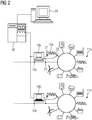
- FIG. 2 For this purpose, a partial area of the energy supply system 10 is shown FIG. 1 with the microgrids 11a and 11b, which at network connection points 12a, b with the in FIG. 2 not shown further distribution network are coupled.
- the local control device 18a, b of the respective microgrid 11a, b is on the one hand in a suitable manner with the power generators or consumers of the respective microgrid 11a, b and on the other hand with a higher-level computing device 20 in connection.
- connection with the power generators or consumers serves to control signals to the respective power generator or consumer to adjust its operating state according to the operating plan for the respective time interval.
- the respective local control device 18a, b connected to measuring sensors, which serve to measure the supply or the reference of electrical energy by the respective power generator or consumer and in the area of the grid connection point 12a, b.
- the local control device is provided with current operating data of the microgrid.
- FIG. 2 merely as an example and representative of all other connections, a connection of the local control device 18a, b shown with the power generator 15a.
- connection comprises a first connection to a control module 21 of the energy generator 21 in order to influence the operating state of the energy generator by control signals, and a second connection to a measuring sensor 22 indicated only schematically for detecting the power fed by the energy generator 15a (for example by suitable measurement of current and voltage at the measuring point of the measuring sensor).
- a connection to a further measuring sensor 23 is shown, with which the power in the area of the network connection point 12a, b is measured.
- the connections between the respective local controller 18a, b and the individual power generators or consumers may be in any suitable form (eg wireless or wired) and may be based on one or more communication protocols (eg according to IEC 61850, IEC 61870-5-104, US Pat. DNP3 (i), XMPP, Modbus TCP / RTU).
- Computing-intensive functions and the configuration and parameterization of the respective microgrid are bundled in the computing device 20, which may be, for example, a cloud computer system.
- the computing device 20 is connected to a data editor 24, which is designed as a separate data processing device (eg, a workstation) or integral Part of the computing device 20 itself can be.
- the connection between the respective controller 18a, b and the computing device 20 may be in any suitable form, e.g. as a wired Ethernet connection, executed. Any communication protocols may be used, for example a protocol defined in the IEC 61850 standard.
- the computing device 20 can likewise be assigned to the operator of one or all of the microgrids 11a, b. Alternatively, however, the computing device 20 can also be operated by a service provider who has expert knowledge in the area of controlling microgrids and offers the parameterization and calculation of the respective optimized operating plans as a service for the respective operator of a microgrid.
- the system for operating a microgrid is constructed as follows and is operated as follows: As described above, the local control device 18a, b assumes communication with the respective energy producers or consumers and with the computing device 20.
- the local control device 18 includes as in FIG. 3 show a first communication interface 31 for communication with the computing device 20 and a second communication interface 32 for transmitting control signals to the respective power producers or consumers.
- An input / output interface 33 also serves to acquire measured values of the respective measuring sensors.
- the measured values can be transmitted to the input / output interface 33 of the control device 18 by hardwiring or converted into a telegram in an intermediately stored process and transmitted as telegram content to the input / output interface 33.
- the input / output interface 33 is accordingly to be designed as a measured value acquisition device or as a communication device.
- the control device 18 comprises a controller module which performs the functions necessary for the control of the energy generator or consumer.
- the controller module may be, for example, a microprocessor, an ASIC or an FPGA or the like.
- the computing device 20 On the basis of heuristics or mathematical optimization methods, the computing device 20 generates operating plans for the energy producers or consumers of the respective microgrid, which ensure a stable system state of the microgrid.
- the computing device 20 is as in FIG. 4 shown formed. According to FIG. 4 the computing device 20 comprises an interface 41 for data exchange with the data editor 24 (cf. FIG. 2 ) and a communication interface 42 for connection to one or more local control devices 18. In addition, the computing device has a controller 43, which is set up to execute function modules 44a-d.
- the representation of the computing device 20 in FIG. 4 is purely functional; As already mentioned above, the computing device can either be a single data processing device or a computer network, for example in the form of a cloud computer system, which is the one in FIG. 2 provides shown elements and functions.
- the essential model data of the energy producers or consumers can be parameterized.
- These model data include the energy producers or consumers and their operating parameters indicating data, such as minimum and maximum power producers, efficiency curves, fuel prices or battery capacities.
- These model data are stored in the functional module 44a, which is a data storage module of the computing device 20; a subset relevant for the respective local control device is forwarded to the local control device 18 and stored in a local data storage module 35 (cf. FIG. 3 ) filed.
- the function module 44b is a module for providing weather forecasts, which polls suitable weather services depending on the construction site of the microgrid in order to obtain local forecasts of weather variables such as wind speed, wind direction, solar irradiation, etc.
- the requested weather services may be provided by the computing device 20 itself or by external providers (weather service providers).
- the functional module 44c is a module for calculating prospective feed-in powers of those energy generators whose power generation output is dependent on the respective current weather situation (eg photovoltaic systems, wind turbines, etc.). To calculate the anticipated feed-in power, at least relevant parts of the weather information provided by the function module 44b and at least parts of the model data stored in the function module 44a (eg efficiency curves) are used.
- the function module 44d is a module for calculating operating plans of the individual microgrids.
- the operating schedules for the respective time interval may include, on the one hand, partial operating plans of the individual energy producers and, on the other hand, an overall operating plan, which indicates the power flow at the grid connection point.
- the function module 44d uses a mathematical application optimization, for example on the basis of mixed-integer-linear programming and optimizes the operation of the microgrid with respect to predetermined parameters, such as the power exchange of the microgrid with the distribution network, operating costs or CO 2 emissions.
- the computing device 20 and the local control device 18 of the respective microgrid work together as follows.
- data entry takes place for configuring and parameterizing the respective microgrid.
- the user first enters the model data of the microgrid via the data editor 24.
- the data editor 24 generates data models for the mathematical deployment optimization from the entered data.
- the model data and the data models derived therefrom are stored in the function module 44a.
- the computing device 20 also sends relevant model data to the respective local control device. Relevant are those model data which are necessary or advantageous for the operation of the respective microgrid 11 by the control device 18 and relate to the energy producers or consumers present in the respective microgrid 11.
- the computing device 20 retrieves current weather forecasts from the weather services at cyclical intervals, eg once a day, and stores them in the function module 44b.
- the function module 44c calculates the estimated energy input for each Power generator within the time interval to be considered, passes this information to the function module 44d, which calculates an operating plan for the respective Microgrid using this information, and / or sends it directly to the local control device.
- a corresponding optimization of the operation of the microgrid takes place in accordance with the optimization specifications.
- operating plans are calculated in each case for successive time intervals of, for example, 15 minutes in duration.
- the computing device 20 sends the operating plan for the respective time interval to the corresponding local control device.
- the operational plan includes an overall operational plan (line flow at the grid connection point, in the case of pure isolated systems it is always zero) and the partial operating plans of the respective energy producers.
- the local controller 18 controls the power generators using the transmitted operating schedules for the respective time interval as explained below.
- the local control device acquires measured values which describe the respective power supply of the energy generator or power consumption of the energy consumers and from this forms the power balance of the microgrid in the form of the difference between supply and removal.
- the power flow at the grid connection point which corresponds to the power balance, can also be measured.
- the local controller determines a positive and a negative reserve power.
- the positive reserve power R pos is determined here as the difference between the maximum possible power output and the actual current power output of all active (switched-on) power generators.
- the negative reserve power R neg is determined as the difference between the actual actual power output and the minimum possible power output of all active power generators.
- the respective energy producers are switched on or off when the relevant switch-on state according to the operating plan in the for current time appropriate time interval on or off;
- the desired value of the power output is transmitted as a rule specification to the respective power generator.
- FIG. 5 shows a bar chart with which the power quotas of the currently energized power generator at two different control times t 1 , t 2 become.
- a first partial column 51 stands for a power quota of a first switched-on energy generator
- a second partial column 52 correspondingly stands for the power quota of a second energy generator.
- a line 53 indicates the current power output of the two power generators set according to the operating plan. It can be seen that the first power generator is fully utilized and the second is partially utilized.
- a dashed line 54 indicates the measured or calculated value of the power balance; it can be seen that at time t 1 more power is required than is fed in by the current specification of the operating plan. If there is a connection to the distribution network, this power is compensated, for example, by additional supply.
- the local control device activates the second power generator to deliver a higher power in response to the difference between the power balance and the actual feed. This is in FIG. 5 indicated by the arrow 55.
- the power output is correspondingly reached (see line 56) and the microgrid can continue to be operated in this operating state without putting additional power generators into operation.
- the current account is a positive deviation from the actual state but smaller than the positive reserve power R pos which is in FIG. 5 is entered as an example (only by way of example, the negative reserve power R neg is entered in Figure 5).
- FIG. 6 Another situation is in FIG. 6 exemplified.
- the power balance (line 61) is above the positive reserve power R pos , which results from the current operating state (line 62) and the power contingents of the switched-on power generators.
- the power quota is shown as a partial column 63 at the control time t 2 .
- FIG. 7 Another situation is in FIG. 7 exemplified.
- the power balance (line 71) is below the negative reserve power R neg , which results from the current operating state (line 72) and the power quotas of the switched-on power generators.
- one of the energy generators active at time t 1 is taken out of operation by the control device, so that only one energy generator with a power contingent remains switched on, which is shown as a partial column 73 at the regulation time t 2 .
- their shadow prices can be taken into account.
- selecting the energy producers to be switched off for example, their shadow prices can also be taken into account.
- the Microgrid goes into emergency mode.
- the difference between the fed-in power and the power drawn is positive, so long as the production plants / batteries with the highest shadow prices off until the difference is back in the control band, or it will be turned on if possible consumers. If the difference between the power fed in and the power drawn is negative, the consumers / batteries with the lowest shadow prices will be switched off until the difference returns to the control band.
- the measured values of the energy generators or at the grid connection point are displayed at cyclic intervals, e.g. every hour, sent to the computer and archived there.
- a renewed deployment optimization is triggered, which initiates a new calculation for the remaining period of the optimization period and / or further periods. This ensures that time and quantity-integral boundary conditions are better met.
Claims (13)
- Procédé pour faire fonctionner un réseau (11) d'alimentation en énergie autarcique, qui a un certain nombre de producteurs (15) d'énergie et un certain nombre de consommateurs (16) d'énergie, dans lequel il est prévu un dispositif (18) local de commande, conçu pour commander les producteurs (15) d'énergie et/ou les consommateurs (16) d'énergie et dans lequel on exécute dans le procédé les stades suivants :- on se procure des données de modèle du réseau (11) d'alimentation en énergie autarcique dans une mémoire de données d'un dispositif (20) d'ordinateur supérieur hiérarchiquement au dispositif (18) local de commande, les données de modèle indiquant les producteurs (15) d'énergie respectifs ainsi que leurs paramètres de fonctionnement ;- on détermine un plan de fonctionnement du réseau (11) d'alimentation en énergie autarcique par le dispositif (20) d'ordinateur, en utilisant les données de modèle, le plan de fonctionnement indiquant l'état de fonctionnement du réseau (11) d'alimentation en énergie autarcique pendant un intervalle de temps déterminé ;- on transmet le plan de fonctionnement au dispositif (18) local de commande ; et- on commande les producteurs (15) d'énergie et/ou les consommateurs (16) d'énergie, conformément aux prescriptions du plan de fonctionnement par le dispositif (18) local de commande,
caractérisé en ce que- le plan de fonctionnement comprend, pour l'intervalle de temps respectif, un plan de fonctionnement d'ensemble, qui indique une puissance électrique en un point (12) de raccordement au réseau, du réseau (11) d'alimentation en énergie autarcique et qui comprend des plans de fonctionnement partiels pour les producteurs (15) d'énergie et/ou les consommateurs (16) d'énergie du réseau (11) d'alimentation en énergie autarcique ; et- en fonctionnement du réseau (11) d'alimentation en énergie autarcique, on forme, par le dispositif (18) local de commande, le bilan de puissance en cours du réseau (11) d'alimentation en énergie autarcique, sous la forme d'une différence entre la puissance injectée dans le réseau (11) d'alimentation en énergie autarcique et la puissance qui en est prélevée ;- on détermine, par le dispositif (18) local de commande une puissance de réserve positive et une puissance de réserve négative du réseau (11) d'alimentation en énergie autarcique, la puissance de réserve positive étant déterminée sous la forme d'une différence entre la cession de puissance possible au maximum et la cession de puissance en cours réelle de tous les producteur d'énergie actifs et la puissance de réserve négative sous la forme d'une différence entre la cession de puissance en cours réelle et la cession de puissance possible au minimum de tous les producteurs d'énergie actifs ;- on compare le bilan de puissance en cours à la puissance de réserve positive et négative ; et- on tire parti du résultat de la comparaison pour commander les producteurs (15) d'énergie. - Procédé suivant la revendication 1,
caractérisé en ce que- pour déterminer le plan de fonctionnement au moyen du dispositif (20) d'ordinateur pendant l'intervalle de temps respectif, on détermine une puissance injectée prévue des producteurs (15) d'énergie respectifs ; et- on tire parti de la puissance injectée prévue des producteurs (15) d'énergie respectifs pour déterminer le plan de fonctionnement. - Procédé suivant la revendication 2,
caractérisé en ce que- on détermine, pour l'intervalle de temps respectif et au moyen du dispositif (20) d'ordinateur, un pronostic météorologique pour la partie du réseau (1) d'alimentation en énergie autarcique ; et- pour les producteurs (15) d'énergie, dont la puissance injectée dépend des conditions météorologiques en cours dans la région du producteur (15) d'énergie respectif, on détermine, en utilisant les informations du pronostic météorologique, qui sont pertinentes pour le fonctionnement du producteur (15) d'énergie respectif, ainsi qu'au moins une partie des données de modèle, la puissance injectée prévisible pour l'intervalle de temps respectif. - Procédé suivant l'une des revendications précédentes,
caractérisé en ce que- on détecte les données de modèle comme entrées d'utilisateur par un éditeur (24) de données mis à disposition par le dispositif (20) d'ordinateur ou relié à celui-ci et on les met dans la mémoire de données du dispositif (20) d'ordinateur. - Procédé suivant l'une des revendications précédentes,
caractérisé en ce que- on forme le dispositif (20) d'ordinateur par un dispositif de traitement de données constitué sous la forme d'un système d'ordinateur nuage. - Procédé suivant l'une des revendications précédentes,
caractérisé en ce que- les plans de fonctionnement partiels comprennent chacun au moins une indication sur un état de branchement et une valeur de consigne de la cession de puissance ou de la consommation de puissance du producteur (15) d'énergie ou du consommateur (16) d'énergie respectif. - Procédé suivant la revendication 6,
caractérisé en ce que- les plans de fonctionnement partiels comprennent aussi une indication sur les coûts, qui se produisent à la production d'énergie ou à la consommation d'énergie du producteur (15) d'énergie ou du consommateur (16) d'énergie respectif. - Procédé suivant l'une des revendications précédentes,
caractérisé en ce que- pour un bilan de puissance, qui est inférieur ou égal à la puissance de réserve positive ou négative, on commande les producteurs (15) d'énergie branchés pour adapter en conséquence leur puissance à injecter ; et- pour un bilan de puissance, qui est plus grand que la puissance de réserve positive ou négative, on modifie l'état de branchement d'au moins un producteur (15) d'énergie. - Procédé suivant la revendication 8,
caractérisé en ce que- dans le cas où, pour un bilan de puissance qui est plus grand que la puissance de réserve positive ou négative, il n'y a pas d'autre producteur (15) d'énergie, dont l'état de branchement peut être modifié, on modifie l'état de branchement d'au moins un consommateur (16) d'énergie. - Procédé suivant l'une des revendications précédentes,
caractérisé en ce que- on détecte, au moyen du dispositif (18) local de commande, alors que le réseau (11) d'alimentation en énergie autarcique est en fonctionnement, des valeurs de mesure, qui indiquent un état de fonctionnement des producteurs (15) d'énergie et/ou des consommateurs (16) d'énergie et/ou de l'ensemble du réseau (11) d'alimentation en énergie autarcique, en un point (12) de connexion au réseau ;- on transmet au moins une partie des valeurs de mesure et/ou de valeurs qui s'en déduisent au dispositif (20) d'ordinateur ; et- le dispositif (20) d'ordinateur détermine, en utilisant les valeurs de mesure transmises et/ou les valeurs qui s'en déduisent, un plan de fonctionnement mis à jour pour l'intervalle de temps en cours ou un intervalle de temps suivant. - Procédé suivant l'une des revendications précédentes,
caractérisé en ce que- on détermine, par le dispositif (20) d'ordinateur, des plans de fonctionnement respectifs de plusieurs réseaux (11) d'alimentation en énergie autarciques ; et- on commande, par le dispositif (18) local respectif de commande, les producteurs (15) d'énergie et/ou les consommateurs (16) d'énergie respectifs, des plusieurs réseaux (11) d'alimentation en énergie autarciques, conformément aux prescriptions du plan de fonctionnement respectif. - Système pour faire fonctionner un réseau (11) d'alimentation en énergie autarcique, le réseau (11) d'alimentation en énergie autarcique ayant un certain nombre de producteurs (15) d'énergie et un certain nombre de consommateurs (16) d'énergie, comprenant- un dispositif (18) local de commande, conçu pour commander les producteurs (15) d'énergie et/ou les consommateurs (16) d'énergie ; et- un dispositif (20) d'ordinateur, qui est supérieure hiérarchiquement au dispositif (18) local de commande et qui a une mémoire de données pour mettre à disposition des données de modèle du réseau (11) d'alimentation en énergie autarcique indiquant les producteurs (15) d'énergie respectifs ainsi que leurs paramètres de fonctionnement ; dans lequel- le dispositif (20) d'ordinateur est conçu pour déterminer un plan de fonctionnement du réseau (11) d'alimentation en énergie autarcique, en utilisant les données de modèle et pour transmettre le plan de fonctionnement au dispositif (18) local de commande, le plan de fonctionnement indiquant l'état de fonctionnement du réseau (11) d'alimentation en énergie autarcique pendant un intervalle de temps déterminé ; et dans lequel- le dispositif (18) local de commande est conçu pour commander les producteurs (15) d'énergie et/ou les consommateurs (16) d'énergie, conformément aux prescriptions du plan de fonctionnement ;
caractérisé en ce que- le plan de fonctionnement comprend, pour l'intervalle de temps respectif, un plan de fonctionnement d'ensemble, qui indique une puissance électrique en un point (12) de connexion au réseau du réseau (11) d'alimentation en énergie autarcique et des plans de fonctionnement partiels des producteurs (15) d'énergie et/ou des consommateurs (16) d'énergie du réseau (11) d'alimentation en énergie autarcique ; et- le dispositif (18) local de commande est conçu pour, alors que le réseau (11) d'alimentation en énergie autarcique est en fonctionnement, former le bilan de puissance en cours du réseau (11) d'alimentation en énergie autarcique sous la forme d'une différence entre la puissance injectée dans le réseau (11) d'alimentation en énergie autarcique et la puissance qui en est prélevée pour déterminer une puissance de réserve positive et une puissance de réserve négative du réseau (11) d'alimentation en énergie autarcique pour comparer le bilan de puissance en cours à la puissance de réserve positive et négative et pour tirer parti du résultat de la comparaison pour commander les producteurs (15) d'énergie, la puissance de réserve positive étant déterminée sous la forme d'une différence entre la cession de puissance possible au maximum et la cession de puissance en cours réelle de tous les producteurs d'énergie actifs et la puissance de réserve négative sous la forme d'une différence entre la cession de puissance en cours réelle et la cession de puissance possible au minimum de tous les producteurs d'énergie actifs. - Système suivant la revendication 12,
caractérisé en ce que- le système est conçu pour faire fonctionner plusieurs réseaux (11) d'alimentation en énergie autarcique ; et- au réseau (11) d'alimentation en énergie autarciques respectif sont associés, respectivement, leurs propres dispositifs (18) locaux de commande, qui sont en liaison avec le dispositif (20) d'ordinateur.
Priority Applications (7)
| Application Number | Priority Date | Filing Date | Title |
|---|---|---|---|
| EP16158006.3A EP3214718B1 (fr) | 2016-03-01 | 2016-03-01 | Procede et systeme de fonctionnement d'un reseau d'alimentation en energie autarcique |
| ES16158006T ES2773478T3 (es) | 2016-03-01 | 2016-03-01 | Procedimiento y sistema para operar una red de suministro de energía autónoma |
| AU2017200542A AU2017200542A1 (en) | 2016-03-01 | 2017-01-27 | Method and system for operating an autonomous energy supply network |
| BR102017003668-5A BR102017003668B1 (pt) | 2016-03-01 | 2017-02-22 | Método e sistema para operar uma rede de suprimento de energia autônoma |
| US15/446,200 US10263427B2 (en) | 2016-03-01 | 2017-03-01 | Method and system for operating an autonomous energy supply network |
| CN201710117927.7A CN107145069A (zh) | 2016-03-01 | 2017-03-01 | 用于运行自主能源供应网络的方法和系统 |
| AU2019200357A AU2019200357B2 (en) | 2016-03-01 | 2019-01-18 | Method and system for operating an autonomous energy supply network |
Applications Claiming Priority (1)
| Application Number | Priority Date | Filing Date | Title |
|---|---|---|---|
| EP16158006.3A EP3214718B1 (fr) | 2016-03-01 | 2016-03-01 | Procede et systeme de fonctionnement d'un reseau d'alimentation en energie autarcique |
Publications (2)
| Publication Number | Publication Date |
|---|---|
| EP3214718A1 EP3214718A1 (fr) | 2017-09-06 |
| EP3214718B1 true EP3214718B1 (fr) | 2019-12-04 |
Family
ID=55453062
Family Applications (1)
| Application Number | Title | Priority Date | Filing Date |
|---|---|---|---|
| EP16158006.3A Active EP3214718B1 (fr) | 2016-03-01 | 2016-03-01 | Procede et systeme de fonctionnement d'un reseau d'alimentation en energie autarcique |
Country Status (6)
| Country | Link |
|---|---|
| US (1) | US10263427B2 (fr) |
| EP (1) | EP3214718B1 (fr) |
| CN (1) | CN107145069A (fr) |
| AU (2) | AU2017200542A1 (fr) |
| BR (1) | BR102017003668B1 (fr) |
| ES (1) | ES2773478T3 (fr) |
Families Citing this family (16)
| Publication number | Priority date | Publication date | Assignee | Title |
|---|---|---|---|---|
| US9786335B2 (en) | 2014-06-05 | 2017-10-10 | Micron Technology, Inc. | Apparatuses and methods for performing logical operations using sensing circuitry |
| US10049054B2 (en) | 2015-04-01 | 2018-08-14 | Micron Technology, Inc. | Virtual register file |
| WO2018049504A1 (fr) * | 2016-09-13 | 2018-03-22 | Green Power Labs Inc. | Procédé et système d'établissement en temps réel d'un prix de rajustement d'énergie pour des micro-réseaux ayant des ressources énergétiques distribuées |
| DE102016125947A1 (de) | 2016-12-30 | 2018-07-05 | Wobben Properties Gmbh | Verfahren zum Steuern eines elektrischen Verteilnetzes |
| CN107798441B (zh) * | 2017-12-01 | 2021-12-21 | 北华航天工业学院 | 一种基于分布式发电的智能微电网系统 |
| DE102017222131A1 (de) * | 2017-12-07 | 2019-06-13 | Siemens Aktiengesellschaft | Verfahren zur Auslegung eines multimodalen Energiesystems und multimodales Energiesystem |
| ES2780050T3 (es) * | 2018-02-05 | 2020-08-21 | Beegy Gmbh | Procedimiento y disposición para la gestión de la carga de los dispositivos eléctricos |
| DE102018124618A1 (de) * | 2018-10-05 | 2020-04-09 | Innogy Se | Steuerung und/oder Regelung von Micro-Grids |
| DE102018221156A1 (de) * | 2018-12-06 | 2020-06-10 | Siemens Aktiengesellschaft | Vorrichtung und Verfahren zur Steuerung von Energieflüssen zwischen Komponenten eines Energiesystems |
| CN109581933A (zh) * | 2018-12-20 | 2019-04-05 | 天津瑞能电气有限公司 | 一种基于高速实时以太网通信的分布式微电网保护系统 |
| CN110131902A (zh) * | 2019-04-18 | 2019-08-16 | 青岛经济技术开发区海尔热水器有限公司 | 多台热水器和其它电器联动的控制方法 |
| DE202019102368U1 (de) * | 2019-04-26 | 2020-07-28 | WAGO Verwaltungsgesellschaft mit beschränkter Haftung | System zur Auslegung eines Niederspannungs-Verteilnetzes an einer Ortsnetzstation |
| US11196256B2 (en) * | 2019-11-27 | 2021-12-07 | Mitsubishi Electric Research Laboratories, Inc. | Methods and systems for a holistic framework for parameter coordination of interconnected microgrid systems against disasters |
| CN112688318B (zh) * | 2020-12-21 | 2022-10-14 | 国网浙江省电力有限公司电力科学研究院 | 一种新能源场站内部调频指令分解模型构建方法 |
| US11888317B2 (en) * | 2021-04-14 | 2024-01-30 | Robert John Alvord | Statistical process control method of demand side management |
| DE102021113134A1 (de) | 2021-05-20 | 2022-11-24 | Herbert Kannegiesser Gmbh | Wäscherei und Verfahren zum Betreiben einer Wäscherei |
Family Cites Families (16)
| Publication number | Priority date | Publication date | Assignee | Title |
|---|---|---|---|---|
| EP2136450A4 (fr) | 2007-03-26 | 2013-06-19 | Vpec Inc | Système d'alimentation |
| DE102007055517A1 (de) * | 2007-09-10 | 2009-03-12 | Siemens Ag | Verfahren zum Betreiben eines Energieversorgungsnetzwerks |
| US8706650B2 (en) * | 2009-01-14 | 2014-04-22 | Integral Analytics, Inc. | Optimization of microgrid energy use and distribution |
| US8620634B2 (en) * | 2009-07-24 | 2013-12-31 | Honeywell International Inc. | Energy resource allocation including renewable energy sources |
| US8401709B2 (en) * | 2009-11-03 | 2013-03-19 | Spirae, Inc. | Dynamic distributed power grid control system |
| US8972070B2 (en) * | 2010-07-02 | 2015-03-03 | Alstom Grid Inc. | Multi-interval dispatch system tools for enabling dispatchers in power grid control centers to manage changes |
| US8965590B2 (en) * | 2011-06-08 | 2015-02-24 | Alstom Grid Inc. | Intelligent electrical distribution grid control system data |
| EP2722960B1 (fr) * | 2011-06-17 | 2016-08-17 | Hitachi, Ltd. | Système de gestion de microréseaux |
| US8862279B2 (en) * | 2011-09-28 | 2014-10-14 | Causam Energy, Inc. | Systems and methods for optimizing microgrid power generation and management with predictive modeling |
| US20130144451A1 (en) * | 2011-10-25 | 2013-06-06 | San Diego State University Research Foundation | Residential and commercial energy management system |
| US9261863B2 (en) * | 2012-01-23 | 2016-02-16 | Earth Networks, Inc. | Optimizing and controlling the energy consumption of a building |
| US8886362B2 (en) * | 2012-03-30 | 2014-11-11 | General Electric Company | Integrated distribution system optimization |
| US9312698B2 (en) * | 2012-12-19 | 2016-04-12 | Robert Bosch Gmbh | System and method for energy distribution |
| JP2014150641A (ja) * | 2013-01-31 | 2014-08-21 | Toshiba Corp | エネルギー管理システム、エネルギー管理方法、プログラムおよびサーバ装置 |
| US9373960B2 (en) * | 2013-03-13 | 2016-06-21 | Oracle International Corporation | Computerized system and method for distributed energy resource scheduling |
| JP6129768B2 (ja) * | 2014-03-07 | 2017-05-17 | 株式会社日立製作所 | 需要家機器運用管理システムおよび方法 |
-
2016
- 2016-03-01 EP EP16158006.3A patent/EP3214718B1/fr active Active
- 2016-03-01 ES ES16158006T patent/ES2773478T3/es active Active
-
2017
- 2017-01-27 AU AU2017200542A patent/AU2017200542A1/en not_active Abandoned
- 2017-02-22 BR BR102017003668-5A patent/BR102017003668B1/pt active IP Right Grant
- 2017-03-01 US US15/446,200 patent/US10263427B2/en active Active
- 2017-03-01 CN CN201710117927.7A patent/CN107145069A/zh active Pending
-
2019
- 2019-01-18 AU AU2019200357A patent/AU2019200357B2/en active Active
Non-Patent Citations (1)
| Title |
|---|
| None * |
Also Published As
| Publication number | Publication date |
|---|---|
| US10263427B2 (en) | 2019-04-16 |
| US20170256948A1 (en) | 2017-09-07 |
| CN107145069A (zh) | 2017-09-08 |
| BR102017003668B1 (pt) | 2021-07-27 |
| EP3214718A1 (fr) | 2017-09-06 |
| ES2773478T3 (es) | 2020-07-13 |
| AU2017200542A1 (en) | 2017-09-21 |
| BR102017003668A2 (pt) | 2017-09-05 |
| AU2019200357A1 (en) | 2019-02-07 |
| AU2019200357B2 (en) | 2020-04-30 |
Similar Documents
| Publication | Publication Date | Title |
|---|---|---|
| EP3214718B1 (fr) | Procede et systeme de fonctionnement d'un reseau d'alimentation en energie autarcique | |
| EP2202470B1 (fr) | Procédé et système destiné à l'utilisation de sources d'énergie renouvelables | |
| EP3048687B1 (fr) | Procede de commande d'un reseau de distribution d'energie electrique | |
| EP3107174B1 (fr) | Procédé, dispositif de commande et système de fonctionnement d'un sous-réseau d'un réseau de distribution d'énergie | |
| EP2628231B1 (fr) | Commande d'un réseau de distribution d'énergie électrique | |
| EP2984724B1 (fr) | Procédé de gestion de la distribution de courant d'un système de production de courant distribué | |
| EP3161928B1 (fr) | Système de gestion d'énergie permettant de commander un dispositif, produit-programme d'ordinateur et procédé de commande d'un dispositif | |
| WO2011020466A2 (fr) | Régulation de centrale électrique | |
| EP3251076A1 (fr) | Procédé d'amélioration de la charge d'un réseau à basse tension | |
| EP3469680A1 (fr) | Procédé, produit programme informatique, dispositif et système de 'service de cluster énergétique' pour gérer des objectifs de régulation, notamment de compensation de charge, lors de la commande de l'approvisionnement, de la conversion, du stockage, de l'alimentation, de la distribution et/ou de la consommation d'énergie dans un réseau d'énergie | |
| EP3635651B1 (fr) | Procédé pour faire fonctionner une pluralité d'unités techniques en tant qu'ensemble sur un réseau de distribution électrique, ainsi que dispositif de commande et dispositif électrique | |
| EP3382841A1 (fr) | Utilisation hybride d'accumulateurs d'énergie | |
| EP3340415A1 (fr) | Procédé de fonctionnement d'un système de gestion d'énergie d'un bâtiment et système de gestion d'énergie | |
| DE102015102430A1 (de) | Autonom und kooperativ gesteuertes Energieeinspeisen in einem virtuellen Kraftwerk | |
| WO2016120248A1 (fr) | Procédé d'amélioration de la répartition des charges d'un réseau basse tension | |
| WO1999009632A2 (fr) | Systeme d'alimentation electrique et procede de fonctionnement d'un reseau d'alimentation en energie | |
| AT514766B1 (de) | Verfahren zur Stabilisierung eines Energieverteilnetzes | |
| EP3667851B1 (fr) | Création de modèles dynamiques de noeuds de réseau dans un réseau de distribution à faible et / ou moyenne tension à l'aide d'un algorithme d' apprentissage automatique | |
| WO2020200569A1 (fr) | Module de coordination, compteur électrique intelligent, marché d'énergie local ainsi que système d'énergie et procédé d'exploitation d'un système d'énergie | |
| WO2021027994A1 (fr) | Procédé pour modéliser une ou plusieurs installations de conversion d'énergie dans un système de gestion d'énergie | |
| EP3869652A1 (fr) | Approvisionnement d'une installation industrielle en énergie électrique | |
| EP4012514A1 (fr) | Procédé de génération d'un plan opérationnel de commande des composants énergétiques d'une infrastructure de bâtiment | |
| WO2024022696A1 (fr) | Charge d'un véhicule électrique à un point de charge d'une maison | |
| DE202019005750U1 (de) | Energiespeichersystem für Mehrzweckanwendungen | |
| WO2018189277A1 (fr) | Pompe à chaleur et procédé de fonctionnement d'une pompe à chaleur |
Legal Events
| Date | Code | Title | Description |
|---|---|---|---|
| PUAI | Public reference made under article 153(3) epc to a published international application that has entered the european phase |
Free format text: ORIGINAL CODE: 0009012 |
|
| STAA | Information on the status of an ep patent application or granted ep patent |
Free format text: STATUS: THE APPLICATION HAS BEEN PUBLISHED |
|
| AK | Designated contracting states |
Kind code of ref document: A1 Designated state(s): AL AT BE BG CH CY CZ DE DK EE ES FI FR GB GR HR HU IE IS IT LI LT LU LV MC MK MT NL NO PL PT RO RS SE SI SK SM TR |
|
| AX | Request for extension of the european patent |
Extension state: BA ME |
|
| STAA | Information on the status of an ep patent application or granted ep patent |
Free format text: STATUS: REQUEST FOR EXAMINATION WAS MADE |
|
| 17P | Request for examination filed |
Effective date: 20180305 |
|
| RBV | Designated contracting states (corrected) |
Designated state(s): AL AT BE BG CH CY CZ DE DK EE ES FI FR GB GR HR HU IE IS IT LI LT LU LV MC MK MT NL NO PL PT RO RS SE SI SK SM TR |
|
| STAA | Information on the status of an ep patent application or granted ep patent |
Free format text: STATUS: EXAMINATION IS IN PROGRESS |
|
| 17Q | First examination report despatched |
Effective date: 20180726 |
|
| GRAP | Despatch of communication of intention to grant a patent |
Free format text: ORIGINAL CODE: EPIDOSNIGR1 |
|
| STAA | Information on the status of an ep patent application or granted ep patent |
Free format text: STATUS: GRANT OF PATENT IS INTENDED |
|
| RIC1 | Information provided on ipc code assigned before grant |
Ipc: H02J 3/14 20060101ALN20190618BHEP Ipc: H02J 3/00 20060101ALN20190618BHEP Ipc: H02J 3/38 20060101AFI20190618BHEP |
|
| INTG | Intention to grant announced |
Effective date: 20190708 |
|
| GRAJ | Information related to disapproval of communication of intention to grant by the applicant or resumption of examination proceedings by the epo deleted |
Free format text: ORIGINAL CODE: EPIDOSDIGR1 |
|
| STAA | Information on the status of an ep patent application or granted ep patent |
Free format text: STATUS: EXAMINATION IS IN PROGRESS |
|
| GRAR | Information related to intention to grant a patent recorded |
Free format text: ORIGINAL CODE: EPIDOSNIGR71 |
|
| GRAS | Grant fee paid |
Free format text: ORIGINAL CODE: EPIDOSNIGR3 |
|
| STAA | Information on the status of an ep patent application or granted ep patent |
Free format text: STATUS: GRANT OF PATENT IS INTENDED |
|
| GRAA | (expected) grant |
Free format text: ORIGINAL CODE: 0009210 |
|
| STAA | Information on the status of an ep patent application or granted ep patent |
Free format text: STATUS: THE PATENT HAS BEEN GRANTED |
|
| INTC | Intention to grant announced (deleted) | ||
| RIC1 | Information provided on ipc code assigned before grant |
Ipc: H02J 3/00 20060101ALN20191015BHEP Ipc: H02J 3/14 20060101ALN20191015BHEP Ipc: H02J 3/38 20060101AFI20191015BHEP |
|
| INTG | Intention to grant announced |
Effective date: 20191024 |
|
| AK | Designated contracting states |
Kind code of ref document: B1 Designated state(s): AL AT BE BG CH CY CZ DE DK EE ES FI FR GB GR HR HU IE IS IT LI LT LU LV MC MK MT NL NO PL PT RO RS SE SI SK SM TR |
|
| REG | Reference to a national code |
Ref country code: GB Ref legal event code: FG4D Free format text: NOT ENGLISH |
|
| REG | Reference to a national code |
Ref country code: CH Ref legal event code: EP |
|
| REG | Reference to a national code |
Ref country code: AT Ref legal event code: REF Ref document number: 1210624 Country of ref document: AT Kind code of ref document: T Effective date: 20191215 |
|
| REG | Reference to a national code |
Ref country code: DE Ref legal event code: R096 Ref document number: 502016007824 Country of ref document: DE |
|
| REG | Reference to a national code |
Ref country code: IE Ref legal event code: FG4D Free format text: LANGUAGE OF EP DOCUMENT: GERMAN |
|
| REG | Reference to a national code |
Ref country code: NL Ref legal event code: MP Effective date: 20191204 |
|
| REG | Reference to a national code |
Ref country code: LT Ref legal event code: MG4D |
|
| PG25 | Lapsed in a contracting state [announced via postgrant information from national office to epo] |
Ref country code: LT Free format text: LAPSE BECAUSE OF FAILURE TO SUBMIT A TRANSLATION OF THE DESCRIPTION OR TO PAY THE FEE WITHIN THE PRESCRIBED TIME-LIMIT Effective date: 20191204 Ref country code: SE Free format text: LAPSE BECAUSE OF FAILURE TO SUBMIT A TRANSLATION OF THE DESCRIPTION OR TO PAY THE FEE WITHIN THE PRESCRIBED TIME-LIMIT Effective date: 20191204 Ref country code: LV Free format text: LAPSE BECAUSE OF FAILURE TO SUBMIT A TRANSLATION OF THE DESCRIPTION OR TO PAY THE FEE WITHIN THE PRESCRIBED TIME-LIMIT Effective date: 20191204 Ref country code: GR Free format text: LAPSE BECAUSE OF FAILURE TO SUBMIT A TRANSLATION OF THE DESCRIPTION OR TO PAY THE FEE WITHIN THE PRESCRIBED TIME-LIMIT Effective date: 20200305 Ref country code: NO Free format text: LAPSE BECAUSE OF FAILURE TO SUBMIT A TRANSLATION OF THE DESCRIPTION OR TO PAY THE FEE WITHIN THE PRESCRIBED TIME-LIMIT Effective date: 20200304 Ref country code: FI Free format text: LAPSE BECAUSE OF FAILURE TO SUBMIT A TRANSLATION OF THE DESCRIPTION OR TO PAY THE FEE WITHIN THE PRESCRIBED TIME-LIMIT Effective date: 20191204 Ref country code: BG Free format text: LAPSE BECAUSE OF FAILURE TO SUBMIT A TRANSLATION OF THE DESCRIPTION OR TO PAY THE FEE WITHIN THE PRESCRIBED TIME-LIMIT Effective date: 20200304 |
|
| PG25 | Lapsed in a contracting state [announced via postgrant information from national office to epo] |
Ref country code: RS Free format text: LAPSE BECAUSE OF FAILURE TO SUBMIT A TRANSLATION OF THE DESCRIPTION OR TO PAY THE FEE WITHIN THE PRESCRIBED TIME-LIMIT Effective date: 20191204 Ref country code: HR Free format text: LAPSE BECAUSE OF FAILURE TO SUBMIT A TRANSLATION OF THE DESCRIPTION OR TO PAY THE FEE WITHIN THE PRESCRIBED TIME-LIMIT Effective date: 20191204 |
|
| PG25 | Lapsed in a contracting state [announced via postgrant information from national office to epo] |
Ref country code: AL Free format text: LAPSE BECAUSE OF FAILURE TO SUBMIT A TRANSLATION OF THE DESCRIPTION OR TO PAY THE FEE WITHIN THE PRESCRIBED TIME-LIMIT Effective date: 20191204 |
|
| REG | Reference to a national code |
Ref country code: ES Ref legal event code: FG2A Ref document number: 2773478 Country of ref document: ES Kind code of ref document: T3 Effective date: 20200713 |
|
| PG25 | Lapsed in a contracting state [announced via postgrant information from national office to epo] |
Ref country code: PT Free format text: LAPSE BECAUSE OF FAILURE TO SUBMIT A TRANSLATION OF THE DESCRIPTION OR TO PAY THE FEE WITHIN THE PRESCRIBED TIME-LIMIT Effective date: 20200429 Ref country code: EE Free format text: LAPSE BECAUSE OF FAILURE TO SUBMIT A TRANSLATION OF THE DESCRIPTION OR TO PAY THE FEE WITHIN THE PRESCRIBED TIME-LIMIT Effective date: 20191204 Ref country code: RO Free format text: LAPSE BECAUSE OF FAILURE TO SUBMIT A TRANSLATION OF THE DESCRIPTION OR TO PAY THE FEE WITHIN THE PRESCRIBED TIME-LIMIT Effective date: 20191204 Ref country code: NL Free format text: LAPSE BECAUSE OF FAILURE TO SUBMIT A TRANSLATION OF THE DESCRIPTION OR TO PAY THE FEE WITHIN THE PRESCRIBED TIME-LIMIT Effective date: 20191204 Ref country code: CZ Free format text: LAPSE BECAUSE OF FAILURE TO SUBMIT A TRANSLATION OF THE DESCRIPTION OR TO PAY THE FEE WITHIN THE PRESCRIBED TIME-LIMIT Effective date: 20191204 |
|
| PG25 | Lapsed in a contracting state [announced via postgrant information from national office to epo] |
Ref country code: IS Free format text: LAPSE BECAUSE OF FAILURE TO SUBMIT A TRANSLATION OF THE DESCRIPTION OR TO PAY THE FEE WITHIN THE PRESCRIBED TIME-LIMIT Effective date: 20200404 Ref country code: SK Free format text: LAPSE BECAUSE OF FAILURE TO SUBMIT A TRANSLATION OF THE DESCRIPTION OR TO PAY THE FEE WITHIN THE PRESCRIBED TIME-LIMIT Effective date: 20191204 Ref country code: SM Free format text: LAPSE BECAUSE OF FAILURE TO SUBMIT A TRANSLATION OF THE DESCRIPTION OR TO PAY THE FEE WITHIN THE PRESCRIBED TIME-LIMIT Effective date: 20191204 |
|
| REG | Reference to a national code |
Ref country code: DE Ref legal event code: R097 Ref document number: 502016007824 Country of ref document: DE |
|
| PLBE | No opposition filed within time limit |
Free format text: ORIGINAL CODE: 0009261 |
|
| STAA | Information on the status of an ep patent application or granted ep patent |
Free format text: STATUS: NO OPPOSITION FILED WITHIN TIME LIMIT |
|
| PG25 | Lapsed in a contracting state [announced via postgrant information from national office to epo] |
Ref country code: DK Free format text: LAPSE BECAUSE OF FAILURE TO SUBMIT A TRANSLATION OF THE DESCRIPTION OR TO PAY THE FEE WITHIN THE PRESCRIBED TIME-LIMIT Effective date: 20191204 Ref country code: MC Free format text: LAPSE BECAUSE OF FAILURE TO SUBMIT A TRANSLATION OF THE DESCRIPTION OR TO PAY THE FEE WITHIN THE PRESCRIBED TIME-LIMIT Effective date: 20191204 |
|
| REG | Reference to a national code |
Ref country code: CH Ref legal event code: PL |
|
| 26N | No opposition filed |
Effective date: 20200907 |
|
| PG25 | Lapsed in a contracting state [announced via postgrant information from national office to epo] |
Ref country code: PL Free format text: LAPSE BECAUSE OF FAILURE TO SUBMIT A TRANSLATION OF THE DESCRIPTION OR TO PAY THE FEE WITHIN THE PRESCRIBED TIME-LIMIT Effective date: 20191204 Ref country code: SI Free format text: LAPSE BECAUSE OF FAILURE TO SUBMIT A TRANSLATION OF THE DESCRIPTION OR TO PAY THE FEE WITHIN THE PRESCRIBED TIME-LIMIT Effective date: 20191204 |
|
| REG | Reference to a national code |
Ref country code: BE Ref legal event code: MM Effective date: 20200331 |
|
| PG25 | Lapsed in a contracting state [announced via postgrant information from national office to epo] |
Ref country code: LU Free format text: LAPSE BECAUSE OF NON-PAYMENT OF DUE FEES Effective date: 20200301 |
|
| PG25 | Lapsed in a contracting state [announced via postgrant information from national office to epo] |
Ref country code: LI Free format text: LAPSE BECAUSE OF NON-PAYMENT OF DUE FEES Effective date: 20200331 Ref country code: CH Free format text: LAPSE BECAUSE OF NON-PAYMENT OF DUE FEES Effective date: 20200331 Ref country code: IE Free format text: LAPSE BECAUSE OF NON-PAYMENT OF DUE FEES Effective date: 20200301 |
|
| PG25 | Lapsed in a contracting state [announced via postgrant information from national office to epo] |
Ref country code: BE Free format text: LAPSE BECAUSE OF NON-PAYMENT OF DUE FEES Effective date: 20200331 |
|
| REG | Reference to a national code |
Ref country code: AT Ref legal event code: MM01 Ref document number: 1210624 Country of ref document: AT Kind code of ref document: T Effective date: 20210301 |
|
| PG25 | Lapsed in a contracting state [announced via postgrant information from national office to epo] |
Ref country code: TR Free format text: LAPSE BECAUSE OF FAILURE TO SUBMIT A TRANSLATION OF THE DESCRIPTION OR TO PAY THE FEE WITHIN THE PRESCRIBED TIME-LIMIT Effective date: 20191204 Ref country code: MT Free format text: LAPSE BECAUSE OF FAILURE TO SUBMIT A TRANSLATION OF THE DESCRIPTION OR TO PAY THE FEE WITHIN THE PRESCRIBED TIME-LIMIT Effective date: 20191204 Ref country code: CY Free format text: LAPSE BECAUSE OF FAILURE TO SUBMIT A TRANSLATION OF THE DESCRIPTION OR TO PAY THE FEE WITHIN THE PRESCRIBED TIME-LIMIT Effective date: 20191204 |
|
| PG25 | Lapsed in a contracting state [announced via postgrant information from national office to epo] |
Ref country code: MK Free format text: LAPSE BECAUSE OF FAILURE TO SUBMIT A TRANSLATION OF THE DESCRIPTION OR TO PAY THE FEE WITHIN THE PRESCRIBED TIME-LIMIT Effective date: 20191204 |
|
| PG25 | Lapsed in a contracting state [announced via postgrant information from national office to epo] |
Ref country code: AT Free format text: LAPSE BECAUSE OF NON-PAYMENT OF DUE FEES Effective date: 20210301 |
|
| PGFP | Annual fee paid to national office [announced via postgrant information from national office to epo] |
Ref country code: FR Payment date: 20230317 Year of fee payment: 8 |
|
| PGFP | Annual fee paid to national office [announced via postgrant information from national office to epo] |
Ref country code: IT Payment date: 20230321 Year of fee payment: 8 Ref country code: DE Payment date: 20220620 Year of fee payment: 8 |
|
| PGFP | Annual fee paid to national office [announced via postgrant information from national office to epo] |
Ref country code: ES Payment date: 20230621 Year of fee payment: 8 |
|
| PGFP | Annual fee paid to national office [announced via postgrant information from national office to epo] |
Ref country code: GB Payment date: 20230403 Year of fee payment: 8 |