EP3214701B1 - Structure for the electrical connection of a busbar to an electrical component - Google Patents
Structure for the electrical connection of a busbar to an electrical component Download PDFInfo
- Publication number
- EP3214701B1 EP3214701B1 EP17158861.9A EP17158861A EP3214701B1 EP 3214701 B1 EP3214701 B1 EP 3214701B1 EP 17158861 A EP17158861 A EP 17158861A EP 3214701 B1 EP3214701 B1 EP 3214701B1
- Authority
- EP
- European Patent Office
- Prior art keywords
- bar
- tab
- leg
- board
- clamp
- Prior art date
- Legal status (The legal status is an assumption and is not a legal conclusion. Google has not performed a legal analysis and makes no representation as to the accuracy of the status listed.)
- Active
Links
- 239000004020 conductor Substances 0.000 claims description 22
- 239000000463 material Substances 0.000 claims description 2
- 238000005476 soldering Methods 0.000 claims 1
- 229910000679 solder Inorganic materials 0.000 description 9
- 230000005540 biological transmission Effects 0.000 description 4
- 238000004519 manufacturing process Methods 0.000 description 4
- 238000006243 chemical reaction Methods 0.000 description 3
- 238000005520 cutting process Methods 0.000 description 3
- 238000010616 electrical installation Methods 0.000 description 2
- 238000005452 bending Methods 0.000 description 1
- 238000005219 brazing Methods 0.000 description 1
- 230000000295 complement effect Effects 0.000 description 1
- 238000001816 cooling Methods 0.000 description 1
- 239000011810 insulating material Substances 0.000 description 1
- 239000012212 insulator Substances 0.000 description 1
- 239000002184 metal Substances 0.000 description 1
- 238000000034 method Methods 0.000 description 1
Images


Classifications
-
- H—ELECTRICITY
- H01—ELECTRIC ELEMENTS
- H01R—ELECTRICALLY-CONDUCTIVE CONNECTIONS; STRUCTURAL ASSOCIATIONS OF A PLURALITY OF MUTUALLY-INSULATED ELECTRICAL CONNECTING ELEMENTS; COUPLING DEVICES; CURRENT COLLECTORS
- H01R4/00—Electrically-conductive connections between two or more conductive members in direct contact, i.e. touching one another; Means for effecting or maintaining such contact; Electrically-conductive connections having two or more spaced connecting locations for conductors and using contact members penetrating insulation
- H01R4/28—Clamped connections, spring connections
- H01R4/48—Clamped connections, spring connections utilising a spring, clip, or other resilient member
-
- H—ELECTRICITY
- H05—ELECTRIC TECHNIQUES NOT OTHERWISE PROVIDED FOR
- H05K—PRINTED CIRCUITS; CASINGS OR CONSTRUCTIONAL DETAILS OF ELECTRIC APPARATUS; MANUFACTURE OF ASSEMBLAGES OF ELECTRICAL COMPONENTS
- H05K1/00—Printed circuits
- H05K1/18—Printed circuits structurally associated with non-printed electric components
- H05K1/181—Printed circuits structurally associated with non-printed electric components associated with surface mounted components
-
- H—ELECTRICITY
- H01—ELECTRIC ELEMENTS
- H01R—ELECTRICALLY-CONDUCTIVE CONNECTIONS; STRUCTURAL ASSOCIATIONS OF A PLURALITY OF MUTUALLY-INSULATED ELECTRICAL CONNECTING ELEMENTS; COUPLING DEVICES; CURRENT COLLECTORS
- H01R12/00—Structural associations of a plurality of mutually-insulated electrical connecting elements, specially adapted for printed circuits, e.g. printed circuit boards [PCB], flat or ribbon cables, or like generally planar structures, e.g. terminal strips, terminal blocks; Coupling devices specially adapted for printed circuits, flat or ribbon cables, or like generally planar structures; Terminals specially adapted for contact with, or insertion into, printed circuits, flat or ribbon cables, or like generally planar structures
- H01R12/50—Fixed connections
- H01R12/51—Fixed connections for rigid printed circuits or like structures
- H01R12/55—Fixed connections for rigid printed circuits or like structures characterised by the terminals
- H01R12/57—Fixed connections for rigid printed circuits or like structures characterised by the terminals surface mounting terminals
-
- H—ELECTRICITY
- H01—ELECTRIC ELEMENTS
- H01F—MAGNETS; INDUCTANCES; TRANSFORMERS; SELECTION OF MATERIALS FOR THEIR MAGNETIC PROPERTIES
- H01F27/00—Details of transformers or inductances, in general
- H01F27/06—Mounting, supporting or suspending transformers, reactors or choke coils not being of the signal type
-
- H—ELECTRICITY
- H01—ELECTRIC ELEMENTS
- H01R—ELECTRICALLY-CONDUCTIVE CONNECTIONS; STRUCTURAL ASSOCIATIONS OF A PLURALITY OF MUTUALLY-INSULATED ELECTRICAL CONNECTING ELEMENTS; COUPLING DEVICES; CURRENT COLLECTORS
- H01R11/00—Individual connecting elements providing two or more spaced connecting locations for conductive members which are, or may be, thereby interconnected, e.g. end pieces for wires or cables supported by the wire or cable and having means for facilitating electrical connection to some other wire, terminal, or conductive member, blocks of binding posts
- H01R11/11—End pieces or tapping pieces for wires, supported by the wire and for facilitating electrical connection to some other wire, terminal or conductive member
- H01R11/28—End pieces consisting of a ferrule or sleeve
-
- H—ELECTRICITY
- H01—ELECTRIC ELEMENTS
- H01R—ELECTRICALLY-CONDUCTIVE CONNECTIONS; STRUCTURAL ASSOCIATIONS OF A PLURALITY OF MUTUALLY-INSULATED ELECTRICAL CONNECTING ELEMENTS; COUPLING DEVICES; CURRENT COLLECTORS
- H01R12/00—Structural associations of a plurality of mutually-insulated electrical connecting elements, specially adapted for printed circuits, e.g. printed circuit boards [PCB], flat or ribbon cables, or like generally planar structures, e.g. terminal strips, terminal blocks; Coupling devices specially adapted for printed circuits, flat or ribbon cables, or like generally planar structures; Terminals specially adapted for contact with, or insertion into, printed circuits, flat or ribbon cables, or like generally planar structures
- H01R12/50—Fixed connections
- H01R12/51—Fixed connections for rigid printed circuits or like structures
- H01R12/55—Fixed connections for rigid printed circuits or like structures characterised by the terminals
- H01R12/58—Fixed connections for rigid printed circuits or like structures characterised by the terminals terminals for insertion into holes
-
- H—ELECTRICITY
- H01—ELECTRIC ELEMENTS
- H01R—ELECTRICALLY-CONDUCTIVE CONNECTIONS; STRUCTURAL ASSOCIATIONS OF A PLURALITY OF MUTUALLY-INSULATED ELECTRICAL CONNECTING ELEMENTS; COUPLING DEVICES; CURRENT COLLECTORS
- H01R12/00—Structural associations of a plurality of mutually-insulated electrical connecting elements, specially adapted for printed circuits, e.g. printed circuit boards [PCB], flat or ribbon cables, or like generally planar structures, e.g. terminal strips, terminal blocks; Coupling devices specially adapted for printed circuits, flat or ribbon cables, or like generally planar structures; Terminals specially adapted for contact with, or insertion into, printed circuits, flat or ribbon cables, or like generally planar structures
- H01R12/70—Coupling devices
- H01R12/7088—Arrangements for power supply
-
- H—ELECTRICITY
- H01—ELECTRIC ELEMENTS
- H01R—ELECTRICALLY-CONDUCTIVE CONNECTIONS; STRUCTURAL ASSOCIATIONS OF A PLURALITY OF MUTUALLY-INSULATED ELECTRICAL CONNECTING ELEMENTS; COUPLING DEVICES; CURRENT COLLECTORS
- H01R12/00—Structural associations of a plurality of mutually-insulated electrical connecting elements, specially adapted for printed circuits, e.g. printed circuit boards [PCB], flat or ribbon cables, or like generally planar structures, e.g. terminal strips, terminal blocks; Coupling devices specially adapted for printed circuits, flat or ribbon cables, or like generally planar structures; Terminals specially adapted for contact with, or insertion into, printed circuits, flat or ribbon cables, or like generally planar structures
- H01R12/70—Coupling devices
- H01R12/71—Coupling devices for rigid printing circuits or like structures
- H01R12/75—Coupling devices for rigid printing circuits or like structures connecting to cables except for flat or ribbon cables
-
- H—ELECTRICITY
- H01—ELECTRIC ELEMENTS
- H01R—ELECTRICALLY-CONDUCTIVE CONNECTIONS; STRUCTURAL ASSOCIATIONS OF A PLURALITY OF MUTUALLY-INSULATED ELECTRICAL CONNECTING ELEMENTS; COUPLING DEVICES; CURRENT COLLECTORS
- H01R25/00—Coupling parts adapted for simultaneous co-operation with two or more identical counterparts, e.g. for distributing energy to two or more circuits
- H01R25/16—Rails or bus-bars provided with a plurality of discrete connecting locations for counterparts
- H01R25/161—Details
- H01R25/162—Electrical connections between or with rails or bus-bars
-
- H—ELECTRICITY
- H01—ELECTRIC ELEMENTS
- H01R—ELECTRICALLY-CONDUCTIVE CONNECTIONS; STRUCTURAL ASSOCIATIONS OF A PLURALITY OF MUTUALLY-INSULATED ELECTRICAL CONNECTING ELEMENTS; COUPLING DEVICES; CURRENT COLLECTORS
- H01R25/00—Coupling parts adapted for simultaneous co-operation with two or more identical counterparts, e.g. for distributing energy to two or more circuits
- H01R25/16—Rails or bus-bars provided with a plurality of discrete connecting locations for counterparts
- H01R25/165—Connecting locations formed by surface mounted apparatus
-
- H—ELECTRICITY
- H01—ELECTRIC ELEMENTS
- H01R—ELECTRICALLY-CONDUCTIVE CONNECTIONS; STRUCTURAL ASSOCIATIONS OF A PLURALITY OF MUTUALLY-INSULATED ELECTRICAL CONNECTING ELEMENTS; COUPLING DEVICES; CURRENT COLLECTORS
- H01R4/00—Electrically-conductive connections between two or more conductive members in direct contact, i.e. touching one another; Means for effecting or maintaining such contact; Electrically-conductive connections having two or more spaced connecting locations for conductors and using contact members penetrating insulation
- H01R4/02—Soldered or welded connections
-
- H—ELECTRICITY
- H02—GENERATION; CONVERSION OR DISTRIBUTION OF ELECTRIC POWER
- H02G—INSTALLATION OF ELECTRIC CABLES OR LINES, OR OF COMBINED OPTICAL AND ELECTRIC CABLES OR LINES
- H02G5/00—Installations of bus-bars
- H02G5/02—Open installations
-
- H—ELECTRICITY
- H01—ELECTRIC ELEMENTS
- H01F—MAGNETS; INDUCTANCES; TRANSFORMERS; SELECTION OF MATERIALS FOR THEIR MAGNETIC PROPERTIES
- H01F27/00—Details of transformers or inductances, in general
- H01F27/06—Mounting, supporting or suspending transformers, reactors or choke coils not being of the signal type
- H01F2027/065—Mounting on printed circuit boards
-
- H—ELECTRICITY
- H01—ELECTRIC ELEMENTS
- H01R—ELECTRICALLY-CONDUCTIVE CONNECTIONS; STRUCTURAL ASSOCIATIONS OF A PLURALITY OF MUTUALLY-INSULATED ELECTRICAL CONNECTING ELEMENTS; COUPLING DEVICES; CURRENT COLLECTORS
- H01R2201/00—Connectors or connections adapted for particular applications
- H01R2201/22—Connectors or connections adapted for particular applications for transformers or coils
-
- H—ELECTRICITY
- H05—ELECTRIC TECHNIQUES NOT OTHERWISE PROVIDED FOR
- H05K—PRINTED CIRCUITS; CASINGS OR CONSTRUCTIONAL DETAILS OF ELECTRIC APPARATUS; MANUFACTURE OF ASSEMBLAGES OF ELECTRICAL COMPONENTS
- H05K2201/00—Indexing scheme relating to printed circuits covered by H05K1/00
- H05K2201/10—Details of components or other objects attached to or integrated in a printed circuit board
- H05K2201/10007—Types of components
- H05K2201/1003—Non-printed inductor
-
- H—ELECTRICITY
- H05—ELECTRIC TECHNIQUES NOT OTHERWISE PROVIDED FOR
- H05K—PRINTED CIRCUITS; CASINGS OR CONSTRUCTIONAL DETAILS OF ELECTRIC APPARATUS; MANUFACTURE OF ASSEMBLAGES OF ELECTRICAL COMPONENTS
- H05K2201/00—Indexing scheme relating to printed circuits covered by H05K1/00
- H05K2201/10—Details of components or other objects attached to or integrated in a printed circuit board
- H05K2201/10227—Other objects, e.g. metallic pieces
- H05K2201/10272—Busbars, i.e. thick metal bars mounted on the printed circuit board [PCB] as high-current conductors
Definitions
- the invention relates to a system for the mechanical and electrical connection of an electrical current transmission bar to an electrical component.
- the invention relates more particularly to a connection system for a module of an electrical installation, comprising an electric current transformer mounted on a printed circuit board, which is connected to a connector of the module by conductive bars for the transmission of strong currents.
- a medium voltage current transmission network comprises in particular a protection cell made up of a plurality of modules having different functions such as, for example, Input / Output, Power, Communication or Current / Voltage Acquisition functions. This makes it possible to offer a wide variety of applications for medium voltage networks.
- One of these modules which is the current / voltage acquisition module, consists of an electrical installation comprising, as main components: a current acquisition transformer (CT Current Transformer), a customer connector which makes it possible to connect the primary of the transformer, an analog conversion chain and a connection connector to the motherboard. These components are mounted on a printed circuit board.
- CT Current Transformer current acquisition transformer
- customer connector which makes it possible to connect the primary of the transformer
- analog conversion chain an analog conversion chain
- connection connector to the motherboard.
- the primary circuit of the transformer is crossed by a high intensity current. This implies using conductors with a large section to make this circuit.
- the wiring of the module using conductors in the form of electric wires is carried out manually by an operator, which involves a risk error, as well as a complexity of the routing of the cables influencing the performance of the module, in particular for so-called crosstalk problems.
- Connecting components with busbars involves bending each bar as it is cabled.
- the rigidity of the bars makes their connection to the transformer difficult and technically complex in its practical realization, without systematically guaranteeing a mechanical connection.
- the object of the invention is to provide a system for the mechanical and electrical connection of a conductor bar to any other electrical component, such as the current transformer, which is simple to implement and which ensures reliable mechanical and electrical connections.
- the invention relates to a mechanical and electrical connection system comprising as defined in claim 1.
- the clamp has a lower part which is received in the second orifice with the tab of the component.
- the plate comprises a layer of continuous conductive material formed at the level of the orifices and which covers at least one lower face of the plate, surrounding the openings of the orifices, and which may also cover the upper face of the plate and the walls. orifices.
- part of the layer of conductive material, which covers a lower face of the plate is covered with a brazing material.
- the clamp consists of at least two hooks jointly delimiting a cylindrical housing and are able to move apart when the tab is introduced into said housing.
- each hook has at least one tongue extending parallel to the main axis of the housing, the lower end of each tongue of which is located vertically below a lower face of the plate and protrudes towards the bottom. outside of the hook.
- the conductive bar consists of two half-bars which are distributed on either side of a median vertical longitudinal plane of the bar and which are connected to each other at their edge. upper end by a fold line.
- each half bar has a hook and half of the foot.
- the fold line forms a broken line and comprises a plurality of windows distributed longitudinally along the fold line.
- the conductive bar is produced by folding a blank of conductive material which has been previously cut and stamped.
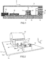
- a module 10 for a protection cell intended to be installed in a medium voltage current transmission line This module 10 is for example a current / voltage acquisition module.
- the module 10 comprises a printed circuit board 12 on which numerous electronic components are mounted.
- the plate 12 extends along a horizontal main plane with the longitudinal direction from front to rear being the direction from right to left with reference to the figure 1 .
- the module 10 here comprises a front connector 14 for mounting and connecting the module 10 in the cell, a current acquisition transformer 16, an analog conversion chain 18 and a rear connector 20 for connecting the module 10 to a card. mother of the cell.
- the transformer 16 comprises a primary circuit 22 which is connected to the front connector 14 and a secondary circuit 24 connected to the analog conversion chain 18.
- the current which circulates between the front connector 14 and the primary circuit 22 comes directly from the secondary circuit d another current transformer (not shown) installed in the cell and is carried by conductors 26.
- the various components of the module 10 are shown here as being mounted on the same upper face 12s of the plate, its lower face 12i being empty.
- module 10 can include other components mounted on this lower face 12i of the plate 12, in addition to those mounted on its upper face 12s.
- each conductor 26 consists of a bar whose section is of rectangular main shape, the great length of its section being vertical.
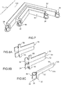
- each bar 26 extends longitudinally. It will be understood that the invention is not limited to this configuration of the bars 26, which can be bent at different angles, as shown for example on figure 7 .
- Each end of a bar 26 is connected to a component of the module 10, that is to say here a first longitudinal end 26a of the bar 26 is connected to the transformer 16, the second end 26b of the bar 26 is connected to the front connector 14.
- first end 26a of the bar 26 is oriented longitudinally. It will be understood that this orientation is not limiting and that one end of a bar 26 can be oriented differently without departing from the scope of the invention, while remaining parallel to the main plane of the plate 12.
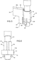
- connection lug 28 for its connection with the bar 26, the electrical component, which here is the transformer 16, has a connection lug 28.
- This tab 28 has a cylindrical shape of revolution and its main axis is vertical perpendicular to the horizontal plane of the plate 12.
- the end 26a of the bar 26 is made to implement its mechanical connection with the lug 28 and with the plate 12, as well as to make the electrical connection of the bar 26 with the lug 28.
- the mechanical connection of the end 26a of the bar 26 with the plate 12 is produced by a foot 30 which extends vertically downwards from a lower edge 26i of the bar 26.
- the foot 30 is introduced into a first orifice 32 complementary formed in the plate 12.
- the vertical length of the foot 30 is greater than the thickness of the plate 12.
- This projecting part makes it possible to provide a contact surface available for the application of solder in order in particular to fix the bar 26 on the plate 12.
- the mechanical connection of the end 26a of the bar 26 with the tab 28 is produced by a clamp 34 which is located at the end of the end 26a of the bar 26 and which receives the tab 28.
- the clamp 34 is elastically deformable, in order to tighten the tab 28.
- the clamp 34 consists of two hooks 36, which extend longitudinally the end 26a of the bar 26 and whose free longitudinal ends of the hooks 36 are transversely distant from one another.
- the hooks 36 are arranged symmetrically with respect to one another with respect to a median vertical longitudinal plane of the end 26a of the bar 26.
- the invention is not limited to this embodiment of the clamp 34, which may have a different number of hooks 36 or else the hooks 36 may not be symmetrical with respect to the median principal plane of the end 26a of bar 26.
- the transverse dimension of the housing 38 defined by the clamp 34 is less than the transverse width of the tab 28, that is to say less than the diameter of the tab 28.
- This spacing of the hooks 36 is limited by the diameter of the orifice 40, that is to say that the hooks 36 come into abutment against the internal face of the orifice 40.
- the tab 28 is thus force-fitted in the housing 38.
- This support makes it possible to achieve a mechanical connection of the tab 28 with the end 26a of the bar 26, as well as an electrical connection since the clamp 34 is made in one piece with the end 26a of the bar 26, in an electrically conductive material.
- the plate 12 comprises a second orifice 40 in which the tab 28 is received.
- part of the clamp 34 is also received in this orifice, with the tab 28.
- each hook 36 of the clamp 34 extends vertically downward beyond the lower edge 26i of the end 26a of the bar 26 and the lower end 36i of each hook 36 is received in the second hole 40.
- the tab 28 is inserted into the clamp 34 and into the second orifice 40 so that its lower end 28i projects vertically downward with respect to the lower face 12i of the plate 12. This part of the tab 28 which is protruding is available to be covered by a layer of solder which allows the tab 28, the plate 12 and the clamp 34 to be fixed together.
- the diameter of the second orifice 40 is substantially equal to the outside diameter of the clamp 34 when it receives the tab 28.
- a continuous layer of solder 42 is deposited on the lower face 12i of the plate 12. This layer of solder 42 covers both the foot 30 of the end 26a of the bar 26 and the lower end 28i of the tab 28 .
- solder layer 42 is also in contact with the lower end 36i of each hook 36.
- the solder layer 42 is, in a known manner, made of an electrically conductive material.
- This layer of solder 42 therefore secures the foot 30 (and therefore the end 26a of the bar 26) and the tab 28 on the plate 12.
- This indirect mechanical connection of the end 26a of the bar 26 with the tab 28 completes the mechanical connection of the end 26a of the bar 26 with the tab 28 by means of the clamp 34.
- the solder layer also forms a second electrical connection of the end 26a of the bar 26 with the tab 28, which completes the electrical connection of the end 26a of the bar 26 with the tab 28 produced at the level of the clamp 34.
- the plate 12 comprises a continuous layer of conductive material 44 which covers the lower face 12i of the plate 12, which surrounds the openings of the first port 32 and the second port 40.
- the layer of conductive material 44 also covers the inner cylindrical wall of the first port 32, the inner cylindrical wall of the second port 40, as well as part of the upper face 12s of plate 12.
- This layer of conductive material 44 is then simultaneously in electrical contact with the end 26a of the bar 26, its foot 30, the hooks 36 of the clamp 34 and the layer of solder 42.
- Each locking tab 46 extends vertically downward from a hook 36 of the clamp 34 and the free lower end 48 of each locking tab 46 is curved to protrude transversely outward from the associated hook 36, as can be seen more particularly at the figure 6 .
- Each locking tab 46 comprises a vertical arm 50 connecting the lower end 48 of the locking tab 46 to the rest of the hook 36, which is preferably produced by cutting or knocking out the arm 50.
- the locking tabs 46 deform transversely towards the inside of the housing 38, to allow the passage of the clamp 34 through the second orifice 40.
- the tab 28 of the component prevents the locking tabs 46 from deforming transversely towards the interior of the housing 38.
- the locking tabs 46 then abut upwards against the underside 12i of the plate 12 when the end 26a of the bar 26 is pulled upwards, thus preventing the end 26a of the bar 26 from moving towards the top.
- each bar 26 is made from two symmetrical and parallel half-bars 52, which are placed against each other by their vertical faces facing each other and which are connected by their respective upper edges.
- the two half-bars 52 are symmetrical with respect to a median vertical longitudinal plane of the bar 26 and are contiguous to one another by their vis-à-vis longitudinal vertical faces.
- a slight transverse play is present between the two half-bars 52. This play allows air circulation between the half-bars 52 and consequently improves the cooling of the bar 26.
- the two half-bars 52 are interconnected at their upper longitudinal edge by a fold line 54.
- the bar 26 is produced by cutting and folding, or routing, a plate of conductive material.
- a blank 56 is formed by cutting the sheet metal plate. This blank is symmetrical with respect to a longitudinal line which will become the fold line 54. The two parts of the blank 56 located on either side of the longitudinal line are intended to form the half-bars 52.
- This blank already comprises two parts 58 intended to form the foot 30.
- the blank 56 is subjected to stamping, in particular to shape the hooks 36.
- the two half-bars 52 are then formed and are distributed on either side of the fold line 54.
- the bar 26 is formed by folding the part obtained at the end of the second step, along the folding line 54.
- the two half bars 52 are then placed against one another, the two hooks are associated to form the clamp 34 and the foot 30 is also formed.
- the fold line 54 is interrupted, that is to say it comprises a plurality of windows 60 distributed along the fold line 54.
- Means for isolating each bar 26 can be placed on the module, in particular in order to protect the module 10 against any short-circuit. This step can be carried out before or after placing the bar 26 on the plate 12.
- each bar 26 is covered with an insulator 62, which is preferably produced by overmolding in order to be best suited to the shape of the bar 26.
Landscapes
- Engineering & Computer Science (AREA)
- Power Engineering (AREA)
- Microelectronics & Electronic Packaging (AREA)
- Coupling Device And Connection With Printed Circuit (AREA)
- Multi-Conductor Connections (AREA)
Description
L'invention se rapporte à un système de connexion mécanique et électrique d'une barre de transmission de courant électrique à un composant électrique.The invention relates to a system for the mechanical and electrical connection of an electrical current transmission bar to an electrical component.
L'invention se rapporte plus particulièrement à un système de connexion pour un module d'une installation électrique, comportant un transformateur de courant électrique monté sur une platine circuit imprimé, qui est relié à un connecteur du module par des barres conductrices pour la transmission de forts courants.The invention relates more particularly to a connection system for a module of an electrical installation, comprising an electric current transformer mounted on a printed circuit board, which is connected to a connector of the module by conductive bars for the transmission of strong currents.
Un réseau de transport de courant de moyenne tension comporte notamment une cellule de protection constituée d'une pluralité de modules ayant des fonctions différentes telles que par exemple les fonctions Entrées/Sorties, Alimentation, Communication ou Acquisition Courant/Tension. Cela permet d'offrir une grande diversité d'applications pour les réseaux moyenne tension.A medium voltage current transmission network comprises in particular a protection cell made up of a plurality of modules having different functions such as, for example, Input / Output, Power, Communication or Current / Voltage Acquisition functions. This makes it possible to offer a wide variety of applications for medium voltage networks.
L'un de ces modules, qui est le module d'acquisition courant/tension consiste en une installation électrique comportant, en tant que composants principaux : un transformateur d'acquisition de courant (CT Current Transformer), un connecteur client qui permet de raccorder le primaire du transformateur, une chaine de conversion analogique et un connecteur de liaison vers la carte mère. Ces composants sont montés sur une platine circuit imprimé (printed circuit board en anglais).One of these modules, which is the current / voltage acquisition module, consists of an electrical installation comprising, as main components: a current acquisition transformer (CT Current Transformer), a customer connector which makes it possible to connect the primary of the transformer, an analog conversion chain and a connection connector to the motherboard. These components are mounted on a printed circuit board.
Le circuit primaire du transformateur est traversé par un courant de forte intensité. Cela implique d'utiliser des conducteurs de section importante pour réaliser ce circuit.The primary circuit of the transformer is crossed by a high intensity current. This implies using conductors with a large section to make this circuit.
Le câblage du module à l'aide de conducteurs sous la forme de fils électriques est réalisé manuellement par un opérateur, ce qui implique un risque d'erreur, ainsi qu'une complexité du cheminement des câbles influant sur la performance du module, notamment pour des problèmes dits de diaphonie.The wiring of the module using conductors in the form of electric wires is carried out manually by an operator, which involves a risk error, as well as a complexity of the routing of the cables influencing the performance of the module, in particular for so-called crosstalk problems.
De plus, un tel mode de câblage a un coût qui augmente avec la complexité de l'opération.In addition, such a wiring method has a cost which increases with the complexity of the operation.
Le raccordement des composants par des barres conductrices implique de plier chaque barre au fur et à mesure du câblage.Connecting components with busbars involves bending each bar as it is cabled.
Aussi, la rigidité des barres rend leur raccordement au transformateur difficile et techniquement complexe dans sa réalisation pratique, sans garantir systématiquement de liaison mécanique.Also, the rigidity of the bars makes their connection to the transformer difficult and technically complex in its practical realization, without systematically guaranteeing a mechanical connection.
Les documentsThe documents
L'invention a pour but de proposer un système de connexion mécanique et électrique d'une barre conductrice à tout autre composant électrique, tel que le transformateur de courant, qui est simple à mettre en œuvre et qui assure des connexions mécanique et électrique fiables.The object of the invention is to provide a system for the mechanical and electrical connection of a conductor bar to any other electrical component, such as the current transformer, which is simple to implement and which ensures reliable mechanical and electrical connections.
L'invention concerne un système de connexion mécanique et électrique comportant que défini dans la revendication 1. The invention relates to a mechanical and electrical connection system comprising as defined in claim 1.
La combinaison des deux orifices de la platine, qui coopèrent chacun avec la barre ou avec la patte du composant électrique et la pince de la barre conductrice permet d'avoir une liaison à la fois mécanique et électrique de la barre avec le composant électrique qui est sûre et efficace.The combination of the two orifices of the plate, which each cooperate with the bar or with the tab of the electrical component and the clamp of the conductive bar makes it possible to have both a mechanical and an electrical connection of the bar with the electrical component which is safe and efficient.
De préférence, la pince comporte une partie inférieure qui est reçue dans le deuxième orifice avec la patte du composant.Preferably, the clamp has a lower part which is received in the second orifice with the tab of the component.
De préférence, la platine comporte une couche de matériau conducteur continue formée au niveau des orifices et qui recouvre au moins une face inférieure de la platine, en entourant les ouvertures des orifices, et qui peut recouvrir aussi la face supérieure de la platine et les parois des orifices.Preferably, the plate comprises a layer of continuous conductive material formed at the level of the orifices and which covers at least one lower face of the plate, surrounding the openings of the orifices, and which may also cover the upper face of the plate and the walls. orifices.
De préférence, une partie de la couche de matériau conducteur, qui recouvre une face inférieure de la platine est recouverte d'un matériau de brasure.Preferably, part of the layer of conductive material, which covers a lower face of the plate is covered with a brazing material.
De préférence, la pince est constituée d'au moins deux crochets délimitant conjointement un logement cylindrique et sont aptes à s'écarter lorsque la patte est introduite dans ledit logement.Preferably, the clamp consists of at least two hooks jointly delimiting a cylindrical housing and are able to move apart when the tab is introduced into said housing.
De préférence, chaque crochet comporte au moins une languette s'étendant parallèlement à l'axe principal du logement, dont l'extrémité inférieure de chaque languette est située verticalement au-dessous d'une face inférieure de la platine et fait saillie vers l'extérieur par rapport au crochet.Preferably, each hook has at least one tongue extending parallel to the main axis of the housing, the lower end of each tongue of which is located vertically below a lower face of the plate and protrudes towards the bottom. outside of the hook.
De préférence, la barre conductrice est constituée de deux demi-barres qui sont réparties de part et d'autre d'un plan longitudinal vertical médian de la barre et qui sont reliées l'une à l'autre au niveau de leur bord d'extrémité supérieur par une ligne de pliage.Preferably, the conductive bar consists of two half-bars which are distributed on either side of a median vertical longitudinal plane of the bar and which are connected to each other at their edge. upper end by a fold line.
De préférence, chaque demi-barre comporte un crochet et une moitié du pied.Preferably, each half bar has a hook and half of the foot.
De préférence, la ligne de pliage forme une ligne discontinue et comporte une pluralité de fenêtres réparties longitudinalement le long de la ligne de pliage.Preferably, the fold line forms a broken line and comprises a plurality of windows distributed longitudinally along the fold line.
De préférence, la barre conductrice est réalisée par pliage d'un flan en matériau conducteur qui a été préalablement découpé et embouti.Preferably, the conductive bar is produced by folding a blank of conductive material which has been previously cut and stamped.
D'autres caractéristiques et avantages de l'invention apparaîtront à la lecture de la description détaillée qui suit pour la compréhension de laquelle on se reportera aux figures annexées parmi lesquelles :
- la
figure 1 est une représentation schématique d'un module comportant un composant et une barre de raccordement reliés selon la structure électrique selon l'invention ; - la
figure 2 est un détail en perspective d'une partie du module représenté à lafigure 1 , montrant la structure selon l'invention ; - la
figure 3 est un éclaté à plus grande échelle du détail représenté à lafigure 2 , montrant les différents composants de la structure électrique avant leur assemblage ; - la
figure 4 est une section selon un plan longitudinal vertical de la structure électrique assemblée ; - les
figures 5 et 6 sont des représentations schématiques d'une variante de réalisation de l'invention dans laquelle la pince porte des pattes de verrouillage ; - la
figure 7 est une représentation schématique d'une partie du module montrant des barres conductrices recouvertes par une couche de matière isolante ; - les
figures 8A à 8C sont des vues montrant différentes étapes de fabrication de la barre conductrice ; - la
figure 9 est une vue similaire à celle de lafigure 8C , montrant une variante de réalisation de la barre conductrice.
- the
figure 1 is a schematic representation of a module comprising a component and a connection bar connected according to the electrical structure according to the invention; - the
figure 2 is a perspective detail of part of the module shown infigure 1 , showing the structure according to the invention; - the
figure 3 is a larger-scale exploded view of the detail shown onfigure 2 , showing the different components of the electrical structure before their assembly; - the
figure 4 is a section along a vertical longitudinal plane of the assembled electrical structure; - the
figures 5 and 6 are schematic representations of an alternative embodiment of the invention in which the clamp carries locking tabs; - the
figure 7 is a schematic representation of part of the module showing conductive bars covered by a layer of insulating material; - the
figures 8A to 8C are views showing different stages in the manufacture of the conductor bar; - the
figure 9 is a view similar to that of thefigure 8C , showing an alternative embodiment of the conductive bar.
Pour la description de l'invention, on adoptera à titre non limitatif les orientations verticale, longitudinale et transversale selon le repère V, L, T indiqué aux figures.For the description of the invention, the vertical, longitudinal and transverse orientations will be adopted without limitation according to the reference V, L, T indicated in the figures.
Dans la description qui va suivre, des éléments identiques, similaires ou analogues seront désignés par les mêmes chiffres de référence.In the description which follows, identical, similar or analogous elements will be designated by the same reference numerals.
On a représenté à la
Le module 10 comporte une platine circuit imprimé12 sur laquelle de nombreux composants électroniques sont montés.The
Dans la description qui va suivre, on considèrera que la platine 12 s'étend selon un plan principal horizontal avec la direction longitudinale d'avant en arrière étant la direction de droite à gauche en se reportant à la
Le module 10 comporte ici un connecteur avant 14 pour le montage et le raccordement du module 10 dans la cellule, un transformateur 16 d'acquisition de courant, une chaine de conversion analogique 18 et un connecteur arrière 20 de raccordement du module 10 à une carte mère de la cellule.The
Le transformateur 16 comporte un circuit primaire 22 qui est raccordé au connecteur avant 14 et un circuit secondaire 24 raccordé à la chaine de conversion analogique 18. Le courant qui circule entre le connecteur avant 14 et le circuit primaire 22 est issu directement du circuit secondaire d'un autre transformateur de courant (non représenté) installé dans la cellule et est transporté par des conducteurs 26.The
Les différents composants du module 10 sont ici représentés comme étant montés sur une même face supérieure 12s de la platine, sa face inférieure 12i étant vide.The various components of the
Il sera compris que le module 10 peut comporter d'autres composants montés sur cette face inférieure 12i de la platine 12, en plus de ceux montés sur sa face supérieure 12s.It will be understood that the
L'intensité de ce courant peut présenter des pics importants, de l'ordre de plusieurs dizaines d'ampères, que les conducteurs 26 doivent être capables de supporter.The intensity of this current can present significant peaks, of the order of several tens of amperes, that the
Comme on peut le voir aux
Selon le mode de réalisation représenté à la
Chaque extrémité d'une barre 26 est reliée à un composant du module 10, c'est-à-dire ici une première extrémité longitudinale 26a de la barre 26 est reliée au transformateur 16, la deuxième extrémité 26b de la barre 26 est reliée au connecteur avant 14.Each end of a
Dans la description qui va suivre, on fera référence à un système réalisant le raccordement de la première extrémité 26a d'une barre 26 au transformateur 16. Il sera compris que cette description peut s'appliquer aussi à la liaison de la première extrémité 26a ou la deuxième extrémité 26b d'une barre 26 avec un autre composant électrique du module 10. Ce composant électrique pouvant aussi être un composant électronique.In the following description, reference will be made to a system making the connection of the
Aussi, à titre de simplification de la description, on considèrera que la première extrémité 26a de la barre 26 est orientée longitudinalement. Il sera compris que cette orientation n'est pas limitative et qu'une extrémité d'une barre 26 peut être orientée différemment sans sortir du domaine de l'invention, tout en restant parallèle au plan principal de la platine 12.Also, by way of simplification of the description, it will be considered that the
Comme on peut le voir plus en détails à la
Cette patte 28 est de forme cylindrique de révolution et son axe principal est vertical perpendiculaire au plan horizontal de la platine 12.This
L'extrémité 26a de la barre 26 est réalisée pour mettre en œuvre sa liaison mécanique avec la patte 28 et avec la platine 12, ainsi que pour réaliser le raccordement électrique de la barre 26 avec la patte 28.The
La liaison mécanique de l'extrémité 26a de la barre 26 avec la platine 12 est réalisée par un pied 30 qui s'étend verticalement vers le bas depuis un bord inférieur 26i de la barre 26. Le pied 30 est introduit dans un premier orifice 32 complémentaire formé dans la platine 12.The mechanical connection of the
De préférence, la longueur verticale du pied 30 est supérieure à l'épaisseur de la platine 12.Preferably, the vertical length of the
Ainsi, lorsque la barre 26 est en position sur la platine 12, l'extrémité inférieure libre 30a du pied 30 fait saillie verticalement vers le bas par rapport à la face inférieure 12i de la platine 12.Thus, when the
Cette partie en saillie permet d'offrir une surface de contact disponible pour l'application de brasure afin notamment de fixer la barre 26 sur la platine 12.This projecting part makes it possible to provide a contact surface available for the application of solder in order in particular to fix the
La liaison mécanique de l'extrémité 26a de la barre 26 avec la patte 28 est réalisée par une pince 34 qui est située en bout de l'extrémité 26a de la barre 26 et qui reçoit la patte 28.The mechanical connection of the
De préférence, la pince 34 est déformable élastiquement, pour réaliser un serrage de la patte 28.Preferably, the
Pour cela, la pince 34 est constituée de deux crochets 36, qui prolongent longitudinalement l'extrémité 26a de la barre 26 et dont les extrémités longitudinales libres des crochets 36 sont distantes transversalement l'une de l'autre.For this, the
Selon le mode de réalisation représenté aux figures, les crochets 36 sont agencés symétriquement l'un par rapport à l'autre par rapport à un plan longitudinal vertical médian de l'extrémité 26a de la barre 26.According to the embodiment shown in the figures, the
Il sera compris que l'invention n'est pas limitée à ce mode de réalisation de la pince 34, qui peut comporter un nombre différent de crochets 36 ou bien les crochets 36 peuvent ne pas être symétriques par rapport au plan principal médian de l'extrémité 26a de la barre 26.It will be understood that the invention is not limited to this embodiment of the
Lorsque la pince 34 est vide, comme c'est notamment le cas dans la vue de la
Cet écartement des crochets 36 est limité par le diamètre de l'orifice 40, c'est dire que les crochets 36 viennent en butée contre la face interne de l'orifice 40.This spacing of the
La patte 28 est ainsi montée à force dans le logement 38.The
Il en résulte que le jeu d'assemblage résiduel entre l'orifice 40, les crochets 36 et la patte 28est quasiment nul, ce qui permet de conserver en permanence un appui des crochets 36 sur la patte 28.As a result, the residual assembly clearance between the
Cet appui permet de réaliser une liaison mécanique de la patte 28 avec l'extrémité 26a de la barre 26, ainsi qu'une liaison électrique puisque la pince 34 est réalisée d'une seule pièce avec l'extrémité 26a de la barre 26, en un matériau conducteur électrique.This support makes it possible to achieve a mechanical connection of the
Selon un autre aspect de la liaison de l'extrémité 26a de la barre 26 avec la patte 28, permettant de maintenir cette liaison, la platine 12 comporte un deuxième orifice 40 dans lequel la patte 28 est reçue.According to another aspect of the connection of the
Selon un mode de réalisation préféré, une partie de la pince 34 est aussi reçue dans cet orifice, avec la patte 28.According to a preferred embodiment, part of the
A cet effet, chaque crochet 36 de la pince 34 s'étend verticalement vers le bas au-delà du bord inférieur 26i de l'extrémité 26a de la barre 26 et l'extrémité inférieure 36i de chaque crochet 36 est reçue dans le deuxième orifice 40.For this purpose, each
Aussi, la patte 28 est insérée dans la pince 34 et dans le deuxième orifice 40 pour que son extrémité inférieure 28i soit en saillie verticalement vers le bas par rapport à la face inférieure 12i de la platine 12. Cette partie de la patte 28 qui est en saillie est disponible pour être recouverte par une couche de brasure qui permet de fixer ensemble la patte 28, la platine 12 et la pince 34.Also, the
De préférence, le diamètre du deuxième orifice 40 est sensiblement égal au diamètre extérieur de la pince 34 lorsque qu'elle reçoit la patte 28.Preferably, the diameter of the
Ainsi, lorsque l'on introduit la patte 28 dans la pince 34, après avoir préalablement monté l'extrémité 26a de la barre 26 sur la platine, les crochets 36 s'écartent l'un de l'autre et viennent en appui contre les parois internes du deuxième orifice 40.Thus, when the
Cela participe au serrage de la patte 28 par la pince 34.This participates in the tightening of the
Selon un autre aspect de la structure d'assemblage, que l'on peut voir à la
Ici, la couche de brasure 42 est aussi en contact avec l'extrémité inférieure 36i de chaque crochet 36.Here, the
La couche de brasure 42 est, de manière connue, réalisée en un matériau conducteur électrique.The
Cette couche de brasure 42 réalise donc la fixation du pied 30 (et donc de l'extrémité 26a de la barre 26) et de la patte 28 sur la platine 12. Cette liaison mécanique indirecte de l'extrémité 26a de la barre 26 avec la patte 28 complète la liaison mécanique de l'extrémité 26a de la barre 26 avec la patte 28 par l'intermédiaire de la pince 34.This layer of
La couche de brasure réalise aussi une deuxième liaison électrique de l'extrémité 26a de la barre 26 avec la patte 28, qui complète la liaison électrique de l'extrémité 26a de la barre 26 avec la patte 28 réalisée au niveau de la pince 34.The solder layer also forms a second electrical connection of the
Afin d'améliorer encore la liaison électrique entre l'extrémité 26a de la barre 26 et la patte 28, la platine 12 comporte une couche continue de matériau conducteur 44 qui recouvre la face inférieure 12i de la platine 12, qui entoure les ouvertures du premier orifice 32 et du deuxième orifice 40. A titre de variante, la couche de matériau conducteur 44 recouvre aussi la paroi cylindrique intérieure du premier orifice 32, la paroi cylindrique intérieure du deuxième orifice 40, ainsi qu'une partie de la face supérieure 12s de la platine 12.In order to further improve the electrical connection between the
Cette couche de matériau conducteur 44 est alors simultanément en contact électrique avec l'extrémité 26a de la barre 26, son pied 30, les crochets 36 de la pince 34 et la couche de brasure 42.This layer of
On a représenté aux
Chaque languette de verrouillage 46 s'étend verticalement vers le bas depuis un crochet 36 de la pince 34 et l'extrémité inférieure libre 48 de chaque languette de verrouillage 46 est recourbée pour faire saillie transversalement vers l'extérieur par rapport au crochet 36 associé, comme on peut le voir plus particulièrement à la
Chaque languette de verrouillage 46 comporte un bras vertical 50 reliant l'extrémité inférieure 48 de la languette de verrouillage 46 au reste du crochet 36, qui est de préférence réalisé par découpe ou défonce du bras 50.Each locking
Lors du montage de l'extrémité 26a de la barre 26 sur la platine 12, les languettes de verrouillage 46 se déforment transversalement vers l'intérieur du logement 38, pour permettre le passage de la pince 34 au travers du deuxième orifice 40.When mounting the
Ensuite, les languettes de verrouillage 46 reprennent leur forme initiale par rapport aux crochets 36.Then, the locking
Comme on peut le voir à la
Ensuite, la patte 28 du composant est introduite dans la pince 34.Then, the
A partir de cet instant, la patte 28 du composant empêche aux languettes de verrouillage 46 de se déformer transversalement vers l'intérieur du logement 38.From this moment, the
Les languettes de verrouillage 46 viennent alors en butée vers le haut contre la face inférieure 12i de la platine 12 lorsque l'extrémité 26a de la barre 26 est tirée vers le haut, empêchant ainsi l'extrémité 26a de la barre 26 de se déplacer vers le haut.The locking
Selon un mode de réalisation préféré, chaque barre 26 est réalisée à partir de deux demi-barres 52 symétriques et parallèles, qui sont accolées l'une contre l'autre par leurs faces verticales en vis-à-vis et qui sont reliées par leurs bords supérieurs respectifs.According to a preferred embodiment, each
Ainsi, lorsque la barre 26 est rectiligne, ou avant son pliage sur la platine 12, comme c'est le cas notamment selon le mode représenté à la
Selon une variante, un léger jeu transversal est présent entre les deux demi-barres 52. Ce jeu permet une circulation d'air entre les demi-barres 52 et améliore par conséquent le refroidissement de la barre 26.According to a variant, a slight transverse play is present between the two half-bars 52. This play allows air circulation between the half-
Les deux demi-barres 52 sont reliées entre elles à leur bord supérieur longitudinal par une ligne de pliage 54.The two half-
Comme on peut le voir aux
Ainsi, selon une première étape représentée par la
Ce flan comporte déjà deux parties 58 destinées à former le pied 30.This blank already comprises two
Ensuite, selon une deuxième étape représentée par la
Enfin, selon une troisième étape représentée par la
Les deux demi barres 52 sont alors accolées l'une contre l'autre, les deux crochets sont associés pour former la pince 34 et le pied 30 est lui aussi formé.The two
Il sera compris que cette méthode de réalisation d'une barre 26 s'appliquerait à l'identique pour une barre dans laquelle les crochets 36 comportent des languettes de verrouillage 46.It will be understood that this method of making a
Afin de faciliter l'opération de pliage, et selon un autre aspect de cette méthode de fabrication de la barre 26 représenté à la
Des moyens d'isolation de chaque barre 26 peuvent être mis en place sur le module, notamment afin de protéger le module 10 contre tout court-circuit. Cette étape peut être réalisée avant ou après mise en place de la barre 26 sur la platine 12.Means for isolating each
Pour cela, comme on peut le voir à la
Claims (8)
- A mechanical and electrical connection system including a printed circuit board (12), a conductor bar (26) and an electrical component (16),
wherein the board includes a first orifice (32) into which a lower leg (30) of the bar (26) is accommodated and includes a second orifice (40) into which a leg (28) of the component (16) is accommodated,
and wherein the bar (26) includes an elastically-deformable clamp (34) which accommodates the leg (28) of the component (16),
characterized in that the clamp (34) consists of at least two hooks (36) delimiting together a cylindrical housing (38) which are adapted to move away from one another when the leg (28) is introduced into said housing (28),
and in that each hook (36) includes a lower portion (36i) which is accommodated into the second orifice (40) with the leg (28) of the component (16). - The system according to any one of the preceding claims, characterized in that the board (12) includes a continuous layer (44) of a conductive material formed at the orifices (32, 40) and which covers at least one lower face (12i) of the board (12), by surrounding the openings of the orifices (32, 40).
- The system according to claim 2, characterized in that a portion of the conductive material layer (44), which covers a lower face (12i) of the board (12), is covered with a soldering material.
- The system according to any one of the preceding claims, characterized in that each hook (36) includes at least one tab (46) extending parallel to the main axis of the housing (28), the lower end (48) of each tab of which is located vertically beneath a lower face (12i) of the board (12) and projects outwardly with respect to the hook (36).
- The system according to any one of the preceding claims, characterized in that the conductor bar (26) consists of two half-bars (52) which are distributed on either side of a vertical longitudinal midplane of the bar (26) and which are linked to one another at their upper end edge by a fold line (54).
- The system according to claim 5, characterized in that each half-bar (52) includes a hook (36) and one half (58) of the leg (30).
- The system according to claim 5, characterized in that the fold line (54) forms a discontinuous line and includes a plurality of windows (60) distributed longitudinally along the fold line (54).
- The system according to any one of claims 5 to 7, characterized in that the conductor bar (26) is made by folding a blank (56) made of a conductive material which has been cut and stamped beforehand.
Applications Claiming Priority (1)
| Application Number | Priority Date | Filing Date | Title |
|---|---|---|---|
| FR1651823A FR3048559B1 (en) | 2016-03-04 | 2016-03-04 | ELECTRICAL STRUCTURE FOR CONNECTING A BAR CONDUCTIVE TO AN ELECTRICAL COMPONENT |
Publications (2)
| Publication Number | Publication Date |
|---|---|
| EP3214701A1 EP3214701A1 (en) | 2017-09-06 |
| EP3214701B1 true EP3214701B1 (en) | 2021-06-30 |
Family
ID=55808705
Family Applications (1)
| Application Number | Title | Priority Date | Filing Date |
|---|---|---|---|
| EP17158861.9A Active EP3214701B1 (en) | 2016-03-04 | 2017-03-02 | Structure for the electrical connection of a busbar to an electrical component |
Country Status (4)
| Country | Link |
|---|---|
| US (1) | US9877394B2 (en) |
| EP (1) | EP3214701B1 (en) |
| CN (1) | CN107154543B (en) |
| FR (1) | FR3048559B1 (en) |
Families Citing this family (3)
| Publication number | Priority date | Publication date | Assignee | Title |
|---|---|---|---|---|
| EP3557602B1 (en) * | 2016-12-15 | 2024-04-24 | Amogreentech Co., Ltd. | Power relay assembly |
| CN207303429U (en) * | 2017-08-23 | 2018-05-01 | 泰科电子(上海)有限公司 | Connector and connector assembly |
| CN108063048B (en) * | 2017-12-12 | 2024-02-27 | 珠海格力新元电子有限公司 | Busbar and capacitor with same |
Citations (4)
| Publication number | Priority date | Publication date | Assignee | Title |
|---|---|---|---|---|
| US4836792A (en) * | 1988-06-13 | 1989-06-06 | Chrysler Motors Corporation | Connector |
| US5807121A (en) * | 1996-05-07 | 1998-09-15 | General Electric Company | Junction component for connecting the electrical leads of a printed circuit board and a separate electrical unit |
| WO2009010705A1 (en) * | 2007-07-18 | 2009-01-22 | Autoliv Development Ab | An electrical unit |
| DE102011121943A1 (en) * | 2011-12-22 | 2013-06-27 | Brose Fahrzeugteile Gmbh & Co. Kommanditgesellschaft, Hallstadt | control electronics |
Family Cites Families (9)
| Publication number | Priority date | Publication date | Assignee | Title |
|---|---|---|---|---|
| US3681738A (en) * | 1971-02-02 | 1972-08-01 | Berg Electronics Inc | Circuit board socket |
| JP3286474B2 (en) * | 1994-09-29 | 2002-05-27 | 三洋電機株式会社 | Electric equipment with built-in battery |
| US5618187A (en) * | 1994-11-17 | 1997-04-08 | The Whitaker Corporation | Board mount bus bar contact |
| US20020098743A1 (en) * | 1998-04-17 | 2002-07-25 | Schell Mark S. | Power connector |
| CA2438678C (en) | 2003-08-26 | 2005-11-15 | Angus Bryden Macdonald | Battery cable clamp |
| US7892022B2 (en) * | 2009-02-06 | 2011-02-22 | Tyco Electronics Corporation | Jumper connector for a lighting assembly |
| DE202009006254U1 (en) * | 2009-04-29 | 2009-07-16 | Harting Electric Gmbh & Co. Kg | Connecting element for electrical conductors with a printed circuit board |
| JP5887150B2 (en) * | 2012-01-26 | 2016-03-16 | Kyb株式会社 | Bus bar |
| CN205724101U (en) * | 2016-04-11 | 2016-11-23 | 安费诺东亚电子科技(深圳)有限公司 | A kind of new micro high current connector |
-
2016
- 2016-03-04 FR FR1651823A patent/FR3048559B1/en not_active Expired - Fee Related
-
2017
- 2017-01-31 US US15/420,875 patent/US9877394B2/en active Active
- 2017-03-02 EP EP17158861.9A patent/EP3214701B1/en active Active
- 2017-03-02 CN CN201710120293.0A patent/CN107154543B/en not_active Expired - Fee Related
Patent Citations (4)
| Publication number | Priority date | Publication date | Assignee | Title |
|---|---|---|---|---|
| US4836792A (en) * | 1988-06-13 | 1989-06-06 | Chrysler Motors Corporation | Connector |
| US5807121A (en) * | 1996-05-07 | 1998-09-15 | General Electric Company | Junction component for connecting the electrical leads of a printed circuit board and a separate electrical unit |
| WO2009010705A1 (en) * | 2007-07-18 | 2009-01-22 | Autoliv Development Ab | An electrical unit |
| DE102011121943A1 (en) * | 2011-12-22 | 2013-06-27 | Brose Fahrzeugteile Gmbh & Co. Kommanditgesellschaft, Hallstadt | control electronics |
Also Published As
| Publication number | Publication date |
|---|---|
| CN107154543A (en) | 2017-09-12 |
| CN107154543B (en) | 2020-03-13 |
| FR3048559B1 (en) | 2018-03-09 |
| US20170257949A1 (en) | 2017-09-07 |
| EP3214701A1 (en) | 2017-09-06 |
| US9877394B2 (en) | 2018-01-23 |
| FR3048559A1 (en) | 2017-09-08 |
Similar Documents
| Publication | Publication Date | Title |
|---|---|---|
| EP3214701B1 (en) | Structure for the electrical connection of a busbar to an electrical component | |
| EP2897234B1 (en) | Male RJ45 plug for RJ45 electrical connection cord | |
| FR2888683A1 (en) | ECONESS FOR CONNECTING CABLE TRUNCTIONS | |
| FR2975835A1 (en) | GROUND CLIP AND EARTH ASSEMBLY | |
| FR2787642A1 (en) | ASSEMBLY OF ELECTRICAL CONNECTORS | |
| FR3062956A1 (en) | FEMALE ELECTRICAL CONNECTION ASSEMBLY | |
| FR2735289A1 (en) | CONNECTION METHOD AND DEVICE FOR SET OF OVER-MOLDED BARS | |
| EP3170227B1 (en) | Electrical connector and electrical connection system | |
| EP3089295B1 (en) | Electrical interconnection device for an equipotential connection between a cable tray piece and an electrical cable piece. | |
| EP2518831B1 (en) | Connecting sleeve for electrical cables | |
| EP2662931B1 (en) | Connection tip for insulated power-supply cable and method for manufacturing said connection tip | |
| FR3032389A1 (en) | ELECTRICAL HEATING DEVICE | |
| EP2079133B1 (en) | Connection terminal equipped with a socket for receiving a pin of an eletric plug, power outlet comprising such a terminal and method of manufacturing such a terminal | |
| FR2936657A1 (en) | Electric connection terminal e.g. phase terminal, for e.g. electric connector, has metallic foil with two tongues whose connected end parts are extended along two directions forming acute angle between directions | |
| FR2797353A1 (en) | Connector for electric conductors e.g. for motor vehicles, has at least one electrically conductive bridge with as many end sections as electric conductors to be connected | |
| EP1968160B1 (en) | Electrical appliance with prioritised automatic electric connections | |
| FR2692724A1 (en) | Wire connector. | |
| EP3336967B1 (en) | Electrical connection element | |
| EP3599669A1 (en) | Female electrical terminal and method for mounting a female electrical terminal | |
| EP1065749B1 (en) | Connection accessory for electrical apparatus, in particular for modular electrical apparatus | |
| EP2850697B1 (en) | Connector for shielded electric cables and corresponding assembly method | |
| EP1528631B1 (en) | Solderless connection system for printed circuits | |
| EP1085553A1 (en) | Process for manufacturing fuse holder modules in serie and fuse holder modules made by this process | |
| FR2721441A1 (en) | Voltage potential divider for use in motor vehicle | |
| FR3073097A1 (en) | ADAPTER FOR ARMORED CONNECTOR, ARMORED CONNECTOR AND METHOD FOR MOUNTING ARMORED CONNECTOR |
Legal Events
| Date | Code | Title | Description |
|---|---|---|---|
| PUAI | Public reference made under article 153(3) epc to a published international application that has entered the european phase |
Free format text: ORIGINAL CODE: 0009012 |
|
| STAA | Information on the status of an ep patent application or granted ep patent |
Free format text: STATUS: THE APPLICATION HAS BEEN PUBLISHED |
|
| AK | Designated contracting states |
Kind code of ref document: A1 Designated state(s): AL AT BE BG CH CY CZ DE DK EE ES FI FR GB GR HR HU IE IS IT LI LT LU LV MC MK MT NL NO PL PT RO RS SE SI SK SM TR |
|
| AX | Request for extension of the european patent |
Extension state: BA ME |
|
| STAA | Information on the status of an ep patent application or granted ep patent |
Free format text: STATUS: REQUEST FOR EXAMINATION WAS MADE |
|
| 17P | Request for examination filed |
Effective date: 20180219 |
|
| RBV | Designated contracting states (corrected) |
Designated state(s): AL AT BE BG CH CY CZ DE DK EE ES FI FR GB GR HR HU IE IS IT LI LT LU LV MC MK MT NL NO PL PT RO RS SE SI SK SM TR |
|
| STAA | Information on the status of an ep patent application or granted ep patent |
Free format text: STATUS: EXAMINATION IS IN PROGRESS |
|
| 17Q | First examination report despatched |
Effective date: 20181203 |
|
| GRAP | Despatch of communication of intention to grant a patent |
Free format text: ORIGINAL CODE: EPIDOSNIGR1 |
|
| STAA | Information on the status of an ep patent application or granted ep patent |
Free format text: STATUS: GRANT OF PATENT IS INTENDED |
|
| INTG | Intention to grant announced |
Effective date: 20210125 |
|
| GRAS | Grant fee paid |
Free format text: ORIGINAL CODE: EPIDOSNIGR3 |
|
| GRAA | (expected) grant |
Free format text: ORIGINAL CODE: 0009210 |
|
| STAA | Information on the status of an ep patent application or granted ep patent |
Free format text: STATUS: THE PATENT HAS BEEN GRANTED |
|
| AK | Designated contracting states |
Kind code of ref document: B1 Designated state(s): AL AT BE BG CH CY CZ DE DK EE ES FI FR GB GR HR HU IE IS IT LI LT LU LV MC MK MT NL NO PL PT RO RS SE SI SK SM TR |
|
| REG | Reference to a national code |
Ref country code: CH Ref legal event code: EP |
|
| REG | Reference to a national code |
Ref country code: AT Ref legal event code: REF Ref document number: 1407214 Country of ref document: AT Kind code of ref document: T Effective date: 20210715 |
|
| REG | Reference to a national code |
Ref country code: DE Ref legal event code: R096 Ref document number: 602017041083 Country of ref document: DE |
|
| REG | Reference to a national code |
Ref country code: IE Ref legal event code: FG4D Free format text: LANGUAGE OF EP DOCUMENT: FRENCH |
|
| REG | Reference to a national code |
Ref country code: LT Ref legal event code: MG9D |
|
| PG25 | Lapsed in a contracting state [announced via postgrant information from national office to epo] |
Ref country code: HR Free format text: LAPSE BECAUSE OF FAILURE TO SUBMIT A TRANSLATION OF THE DESCRIPTION OR TO PAY THE FEE WITHIN THE PRESCRIBED TIME-LIMIT Effective date: 20210630 Ref country code: BG Free format text: LAPSE BECAUSE OF FAILURE TO SUBMIT A TRANSLATION OF THE DESCRIPTION OR TO PAY THE FEE WITHIN THE PRESCRIBED TIME-LIMIT Effective date: 20210930 Ref country code: FI Free format text: LAPSE BECAUSE OF FAILURE TO SUBMIT A TRANSLATION OF THE DESCRIPTION OR TO PAY THE FEE WITHIN THE PRESCRIBED TIME-LIMIT Effective date: 20210630 |
|
| REG | Reference to a national code |
Ref country code: NL Ref legal event code: MP Effective date: 20210630 |
|
| REG | Reference to a national code |
Ref country code: AT Ref legal event code: MK05 Ref document number: 1407214 Country of ref document: AT Kind code of ref document: T Effective date: 20210630 |
|
| PG25 | Lapsed in a contracting state [announced via postgrant information from national office to epo] |
Ref country code: LV Free format text: LAPSE BECAUSE OF FAILURE TO SUBMIT A TRANSLATION OF THE DESCRIPTION OR TO PAY THE FEE WITHIN THE PRESCRIBED TIME-LIMIT Effective date: 20210630 Ref country code: GR Free format text: LAPSE BECAUSE OF FAILURE TO SUBMIT A TRANSLATION OF THE DESCRIPTION OR TO PAY THE FEE WITHIN THE PRESCRIBED TIME-LIMIT Effective date: 20211001 Ref country code: NO Free format text: LAPSE BECAUSE OF FAILURE TO SUBMIT A TRANSLATION OF THE DESCRIPTION OR TO PAY THE FEE WITHIN THE PRESCRIBED TIME-LIMIT Effective date: 20210930 Ref country code: SE Free format text: LAPSE BECAUSE OF FAILURE TO SUBMIT A TRANSLATION OF THE DESCRIPTION OR TO PAY THE FEE WITHIN THE PRESCRIBED TIME-LIMIT Effective date: 20210630 Ref country code: RS Free format text: LAPSE BECAUSE OF FAILURE TO SUBMIT A TRANSLATION OF THE DESCRIPTION OR TO PAY THE FEE WITHIN THE PRESCRIBED TIME-LIMIT Effective date: 20210630 |
|
| PG25 | Lapsed in a contracting state [announced via postgrant information from national office to epo] |
Ref country code: SK Free format text: LAPSE BECAUSE OF FAILURE TO SUBMIT A TRANSLATION OF THE DESCRIPTION OR TO PAY THE FEE WITHIN THE PRESCRIBED TIME-LIMIT Effective date: 20210630 Ref country code: SM Free format text: LAPSE BECAUSE OF FAILURE TO SUBMIT A TRANSLATION OF THE DESCRIPTION OR TO PAY THE FEE WITHIN THE PRESCRIBED TIME-LIMIT Effective date: 20210630 Ref country code: CZ Free format text: LAPSE BECAUSE OF FAILURE TO SUBMIT A TRANSLATION OF THE DESCRIPTION OR TO PAY THE FEE WITHIN THE PRESCRIBED TIME-LIMIT Effective date: 20210630 Ref country code: EE Free format text: LAPSE BECAUSE OF FAILURE TO SUBMIT A TRANSLATION OF THE DESCRIPTION OR TO PAY THE FEE WITHIN THE PRESCRIBED TIME-LIMIT Effective date: 20210630 Ref country code: AT Free format text: LAPSE BECAUSE OF FAILURE TO SUBMIT A TRANSLATION OF THE DESCRIPTION OR TO PAY THE FEE WITHIN THE PRESCRIBED TIME-LIMIT Effective date: 20210630 Ref country code: RO Free format text: LAPSE BECAUSE OF FAILURE TO SUBMIT A TRANSLATION OF THE DESCRIPTION OR TO PAY THE FEE WITHIN THE PRESCRIBED TIME-LIMIT Effective date: 20210630 Ref country code: NL Free format text: LAPSE BECAUSE OF FAILURE TO SUBMIT A TRANSLATION OF THE DESCRIPTION OR TO PAY THE FEE WITHIN THE PRESCRIBED TIME-LIMIT Effective date: 20210630 Ref country code: PT Free format text: LAPSE BECAUSE OF FAILURE TO SUBMIT A TRANSLATION OF THE DESCRIPTION OR TO PAY THE FEE WITHIN THE PRESCRIBED TIME-LIMIT Effective date: 20211102 Ref country code: ES Free format text: LAPSE BECAUSE OF FAILURE TO SUBMIT A TRANSLATION OF THE DESCRIPTION OR TO PAY THE FEE WITHIN THE PRESCRIBED TIME-LIMIT Effective date: 20210630 |
|
| PG25 | Lapsed in a contracting state [announced via postgrant information from national office to epo] |
Ref country code: PL Free format text: LAPSE BECAUSE OF FAILURE TO SUBMIT A TRANSLATION OF THE DESCRIPTION OR TO PAY THE FEE WITHIN THE PRESCRIBED TIME-LIMIT Effective date: 20210630 |
|
| REG | Reference to a national code |
Ref country code: DE Ref legal event code: R097 Ref document number: 602017041083 Country of ref document: DE |
|
| PG25 | Lapsed in a contracting state [announced via postgrant information from national office to epo] |
Ref country code: DK Free format text: LAPSE BECAUSE OF FAILURE TO SUBMIT A TRANSLATION OF THE DESCRIPTION OR TO PAY THE FEE WITHIN THE PRESCRIBED TIME-LIMIT Effective date: 20210630 |
|
| PLBE | No opposition filed within time limit |
Free format text: ORIGINAL CODE: 0009261 |
|
| STAA | Information on the status of an ep patent application or granted ep patent |
Free format text: STATUS: NO OPPOSITION FILED WITHIN TIME LIMIT |
|
| PG25 | Lapsed in a contracting state [announced via postgrant information from national office to epo] |
Ref country code: AL Free format text: LAPSE BECAUSE OF FAILURE TO SUBMIT A TRANSLATION OF THE DESCRIPTION OR TO PAY THE FEE WITHIN THE PRESCRIBED TIME-LIMIT Effective date: 20210630 |
|
| 26N | No opposition filed |
Effective date: 20220331 |
|
| PG25 | Lapsed in a contracting state [announced via postgrant information from national office to epo] |
Ref country code: IT Free format text: LAPSE BECAUSE OF FAILURE TO SUBMIT A TRANSLATION OF THE DESCRIPTION OR TO PAY THE FEE WITHIN THE PRESCRIBED TIME-LIMIT Effective date: 20210630 |
|
| REG | Reference to a national code |
Ref country code: DE Ref legal event code: R119 Ref document number: 602017041083 Country of ref document: DE |
|
| PG25 | Lapsed in a contracting state [announced via postgrant information from national office to epo] |
Ref country code: MC Free format text: LAPSE BECAUSE OF FAILURE TO SUBMIT A TRANSLATION OF THE DESCRIPTION OR TO PAY THE FEE WITHIN THE PRESCRIBED TIME-LIMIT Effective date: 20210630 |
|
| REG | Reference to a national code |
Ref country code: CH Ref legal event code: PL |
|
| GBPC | Gb: european patent ceased through non-payment of renewal fee |
Effective date: 20220302 |
|
| REG | Reference to a national code |
Ref country code: BE Ref legal event code: MM Effective date: 20220331 |
|
| PG25 | Lapsed in a contracting state [announced via postgrant information from national office to epo] |
Ref country code: LU Free format text: LAPSE BECAUSE OF NON-PAYMENT OF DUE FEES Effective date: 20220302 Ref country code: LI Free format text: LAPSE BECAUSE OF NON-PAYMENT OF DUE FEES Effective date: 20220331 Ref country code: IE Free format text: LAPSE BECAUSE OF NON-PAYMENT OF DUE FEES Effective date: 20220302 Ref country code: GB Free format text: LAPSE BECAUSE OF NON-PAYMENT OF DUE FEES Effective date: 20220302 Ref country code: FR Free format text: LAPSE BECAUSE OF NON-PAYMENT OF DUE FEES Effective date: 20220331 Ref country code: DE Free format text: LAPSE BECAUSE OF NON-PAYMENT OF DUE FEES Effective date: 20221001 Ref country code: CH Free format text: LAPSE BECAUSE OF NON-PAYMENT OF DUE FEES Effective date: 20220331 |
|
| PG25 | Lapsed in a contracting state [announced via postgrant information from national office to epo] |
Ref country code: BE Free format text: LAPSE BECAUSE OF NON-PAYMENT OF DUE FEES Effective date: 20220331 |
|
| PG25 | Lapsed in a contracting state [announced via postgrant information from national office to epo] |
Ref country code: LT Free format text: LAPSE BECAUSE OF FAILURE TO SUBMIT A TRANSLATION OF THE DESCRIPTION OR TO PAY THE FEE WITHIN THE PRESCRIBED TIME-LIMIT Effective date: 20210630 |
|
| PG25 | Lapsed in a contracting state [announced via postgrant information from national office to epo] |
Ref country code: HU Free format text: LAPSE BECAUSE OF FAILURE TO SUBMIT A TRANSLATION OF THE DESCRIPTION OR TO PAY THE FEE WITHIN THE PRESCRIBED TIME-LIMIT; INVALID AB INITIO Effective date: 20170302 |
|
| PG25 | Lapsed in a contracting state [announced via postgrant information from national office to epo] |
Ref country code: MK Free format text: LAPSE BECAUSE OF FAILURE TO SUBMIT A TRANSLATION OF THE DESCRIPTION OR TO PAY THE FEE WITHIN THE PRESCRIBED TIME-LIMIT Effective date: 20210630 Ref country code: CY Free format text: LAPSE BECAUSE OF FAILURE TO SUBMIT A TRANSLATION OF THE DESCRIPTION OR TO PAY THE FEE WITHIN THE PRESCRIBED TIME-LIMIT Effective date: 20210630 |