EP3214014B1 - Syringe container - Google Patents
Syringe container Download PDFInfo
- Publication number
- EP3214014B1 EP3214014B1 EP15854713.3A EP15854713A EP3214014B1 EP 3214014 B1 EP3214014 B1 EP 3214014B1 EP 15854713 A EP15854713 A EP 15854713A EP 3214014 B1 EP3214014 B1 EP 3214014B1
- Authority
- EP
- European Patent Office
- Prior art keywords
- cylinder
- lid
- syringe
- container
- mounting cylinder
- Prior art date
- Legal status (The legal status is an assumption and is not a legal conclusion. Google has not performed a legal analysis and makes no representation as to the accuracy of the status listed.)
- Active
Links
- 238000012856 packing Methods 0.000 claims description 53
- 230000000630 rising effect Effects 0.000 claims description 5
- 239000000758 substrate Substances 0.000 description 6
- 238000006073 displacement reaction Methods 0.000 description 3
- 230000005489 elastic deformation Effects 0.000 description 3
- 238000007789 sealing Methods 0.000 description 3
- 229920001971 elastomer Polymers 0.000 description 2
- 239000007788 liquid Substances 0.000 description 2
- 230000001419 dependent effect Effects 0.000 description 1
- 230000006866 deterioration Effects 0.000 description 1
- 230000000694 effects Effects 0.000 description 1
- 239000000806 elastomer Substances 0.000 description 1
- 239000007779 soft material Substances 0.000 description 1
- 230000007306 turnover Effects 0.000 description 1
Images


Classifications
-
- A—HUMAN NECESSITIES
- A61—MEDICAL OR VETERINARY SCIENCE; HYGIENE
- A61J—CONTAINERS SPECIALLY ADAPTED FOR MEDICAL OR PHARMACEUTICAL PURPOSES; DEVICES OR METHODS SPECIALLY ADAPTED FOR BRINGING PHARMACEUTICAL PRODUCTS INTO PARTICULAR PHYSICAL OR ADMINISTERING FORMS; DEVICES FOR ADMINISTERING FOOD OR MEDICINES ORALLY; BABY COMFORTERS; DEVICES FOR RECEIVING SPITTLE
- A61J1/00—Containers specially adapted for medical or pharmaceutical purposes
- A61J1/14—Details; Accessories therefor
- A61J1/20—Arrangements for transferring or mixing fluids, e.g. from vial to syringe
- A61J1/2003—Accessories used in combination with means for transfer or mixing of fluids, e.g. for activating fluid flow, separating fluids, filtering fluid or venting
- A61J1/202—Separating means
- A61J1/2037—Separating means having valve means
-
- A—HUMAN NECESSITIES
- A61—MEDICAL OR VETERINARY SCIENCE; HYGIENE
- A61M—DEVICES FOR INTRODUCING MEDIA INTO, OR ONTO, THE BODY; DEVICES FOR TRANSDUCING BODY MEDIA OR FOR TAKING MEDIA FROM THE BODY; DEVICES FOR PRODUCING OR ENDING SLEEP OR STUPOR
- A61M5/00—Devices for bringing media into the body in a subcutaneous, intra-vascular or intramuscular way; Accessories therefor, e.g. filling or cleaning devices, arm-rests
- A61M5/178—Syringes
- A61M5/31—Details
- A61M5/3129—Syringe barrels
-
- A—HUMAN NECESSITIES
- A61—MEDICAL OR VETERINARY SCIENCE; HYGIENE
- A61M—DEVICES FOR INTRODUCING MEDIA INTO, OR ONTO, THE BODY; DEVICES FOR TRANSDUCING BODY MEDIA OR FOR TAKING MEDIA FROM THE BODY; DEVICES FOR PRODUCING OR ENDING SLEEP OR STUPOR
- A61M5/00—Devices for bringing media into the body in a subcutaneous, intra-vascular or intramuscular way; Accessories therefor, e.g. filling or cleaning devices, arm-rests
- A61M5/178—Syringes
- A61M5/31—Details
- A61M5/3148—Means for causing or aiding aspiration or plunger retraction
-
- A—HUMAN NECESSITIES
- A61—MEDICAL OR VETERINARY SCIENCE; HYGIENE
- A61M—DEVICES FOR INTRODUCING MEDIA INTO, OR ONTO, THE BODY; DEVICES FOR TRANSDUCING BODY MEDIA OR FOR TAKING MEDIA FROM THE BODY; DEVICES FOR PRODUCING OR ENDING SLEEP OR STUPOR
- A61M5/00—Devices for bringing media into the body in a subcutaneous, intra-vascular or intramuscular way; Accessories therefor, e.g. filling or cleaning devices, arm-rests
- A61M5/178—Syringes
- A61M5/31—Details
- A61M5/315—Pistons; Piston-rods; Guiding, blocking or restricting the movement of the rod or piston; Appliances on the rod for facilitating dosing ; Dosing mechanisms
- A61M5/31565—Administration mechanisms, i.e. constructional features, modes of administering a dose
- A61M5/31576—Constructional features or modes of drive mechanisms for piston rods
- A61M5/31583—Constructional features or modes of drive mechanisms for piston rods based on rotational translation, i.e. movement of piston rod is caused by relative rotation between the user activated actuator and the piston rod
-
- A—HUMAN NECESSITIES
- A61—MEDICAL OR VETERINARY SCIENCE; HYGIENE
- A61M—DEVICES FOR INTRODUCING MEDIA INTO, OR ONTO, THE BODY; DEVICES FOR TRANSDUCING BODY MEDIA OR FOR TAKING MEDIA FROM THE BODY; DEVICES FOR PRODUCING OR ENDING SLEEP OR STUPOR
- A61M5/00—Devices for bringing media into the body in a subcutaneous, intra-vascular or intramuscular way; Accessories therefor, e.g. filling or cleaning devices, arm-rests
- A61M5/178—Syringes
- A61M5/31—Details
- A61M5/32—Needles; Details of needles pertaining to their connection with syringe or hub; Accessories for bringing the needle into, or holding the needle on, the body; Devices for protection of needles
- A61M5/3202—Devices for protection of the needle before use, e.g. caps
-
- B—PERFORMING OPERATIONS; TRANSPORTING
- B01—PHYSICAL OR CHEMICAL PROCESSES OR APPARATUS IN GENERAL
- B01L—CHEMICAL OR PHYSICAL LABORATORY APPARATUS FOR GENERAL USE
- B01L3/00—Containers or dishes for laboratory use, e.g. laboratory glassware; Droppers
- B01L3/02—Burettes; Pipettes
- B01L3/021—Pipettes, i.e. with only one conduit for withdrawing and redistributing liquids
-
- B—PERFORMING OPERATIONS; TRANSPORTING
- B01—PHYSICAL OR CHEMICAL PROCESSES OR APPARATUS IN GENERAL
- B01L—CHEMICAL OR PHYSICAL LABORATORY APPARATUS FOR GENERAL USE
- B01L3/00—Containers or dishes for laboratory use, e.g. laboratory glassware; Droppers
- B01L3/02—Burettes; Pipettes
- B01L3/0241—Drop counters; Drop formers
-
- B—PERFORMING OPERATIONS; TRANSPORTING
- B65—CONVEYING; PACKING; STORING; HANDLING THIN OR FILAMENTARY MATERIAL
- B65D—CONTAINERS FOR STORAGE OR TRANSPORT OF ARTICLES OR MATERIALS, e.g. BAGS, BARRELS, BOTTLES, BOXES, CANS, CARTONS, CRATES, DRUMS, JARS, TANKS, HOPPERS, FORWARDING CONTAINERS; ACCESSORIES, CLOSURES, OR FITTINGS THEREFOR; PACKAGING ELEMENTS; PACKAGES
- B65D51/00—Closures not otherwise provided for
- B65D51/24—Closures not otherwise provided for combined or co-operating with auxiliary devices for non-closing purposes
- B65D51/32—Closures not otherwise provided for combined or co-operating with auxiliary devices for non-closing purposes with brushes or rods for applying or stirring contents
-
- B—PERFORMING OPERATIONS; TRANSPORTING
- B65—CONVEYING; PACKING; STORING; HANDLING THIN OR FILAMENTARY MATERIAL
- B65D—CONTAINERS FOR STORAGE OR TRANSPORT OF ARTICLES OR MATERIALS, e.g. BAGS, BARRELS, BOTTLES, BOXES, CANS, CARTONS, CRATES, DRUMS, JARS, TANKS, HOPPERS, FORWARDING CONTAINERS; ACCESSORIES, CLOSURES, OR FITTINGS THEREFOR; PACKAGING ELEMENTS; PACKAGES
- B65D53/00—Sealing or packing elements; Sealings formed by liquid or plastics material
- B65D53/02—Collars or rings
-
- A—HUMAN NECESSITIES
- A61—MEDICAL OR VETERINARY SCIENCE; HYGIENE
- A61J—CONTAINERS SPECIALLY ADAPTED FOR MEDICAL OR PHARMACEUTICAL PURPOSES; DEVICES OR METHODS SPECIALLY ADAPTED FOR BRINGING PHARMACEUTICAL PRODUCTS INTO PARTICULAR PHYSICAL OR ADMINISTERING FORMS; DEVICES FOR ADMINISTERING FOOD OR MEDICINES ORALLY; BABY COMFORTERS; DEVICES FOR RECEIVING SPITTLE
- A61J1/00—Containers specially adapted for medical or pharmaceutical purposes
- A61J1/14—Details; Accessories therefor
- A61J1/20—Arrangements for transferring or mixing fluids, e.g. from vial to syringe
- A61J1/2096—Combination of a vial and a syringe for transferring or mixing their contents
-
- A—HUMAN NECESSITIES
- A61—MEDICAL OR VETERINARY SCIENCE; HYGIENE
- A61M—DEVICES FOR INTRODUCING MEDIA INTO, OR ONTO, THE BODY; DEVICES FOR TRANSDUCING BODY MEDIA OR FOR TAKING MEDIA FROM THE BODY; DEVICES FOR PRODUCING OR ENDING SLEEP OR STUPOR
- A61M5/00—Devices for bringing media into the body in a subcutaneous, intra-vascular or intramuscular way; Accessories therefor, e.g. filling or cleaning devices, arm-rests
- A61M5/178—Syringes
- A61M5/24—Ampoule syringes, i.e. syringes with needle for use in combination with replaceable ampoules or carpules, e.g. automatic
- A61M2005/2485—Ampoule holder connected to rest of syringe
- A61M2005/2488—Ampoule holder connected to rest of syringe via rotation, e.g. threads or bayonet
-
- B—PERFORMING OPERATIONS; TRANSPORTING
- B01—PHYSICAL OR CHEMICAL PROCESSES OR APPARATUS IN GENERAL
- B01L—CHEMICAL OR PHYSICAL LABORATORY APPARATUS FOR GENERAL USE
- B01L2200/00—Solutions for specific problems relating to chemical or physical laboratory apparatus
- B01L2200/06—Fluid handling related problems
- B01L2200/0605—Metering of fluids
-
- B—PERFORMING OPERATIONS; TRANSPORTING
- B01—PHYSICAL OR CHEMICAL PROCESSES OR APPARATUS IN GENERAL
- B01L—CHEMICAL OR PHYSICAL LABORATORY APPARATUS FOR GENERAL USE
- B01L2300/00—Additional constructional details
- B01L2300/04—Closures and closing means
- B01L2300/041—Connecting closures to device or container
- B01L2300/042—Caps; Plugs
-
- B—PERFORMING OPERATIONS; TRANSPORTING
- B01—PHYSICAL OR CHEMICAL PROCESSES OR APPARATUS IN GENERAL
- B01L—CHEMICAL OR PHYSICAL LABORATORY APPARATUS FOR GENERAL USE
- B01L2300/00—Additional constructional details
- B01L2300/04—Closures and closing means
- B01L2300/046—Function or devices integrated in the closure
- B01L2300/047—Additional chamber, reservoir
-
- B—PERFORMING OPERATIONS; TRANSPORTING
- B01—PHYSICAL OR CHEMICAL PROCESSES OR APPARATUS IN GENERAL
- B01L—CHEMICAL OR PHYSICAL LABORATORY APPARATUS FOR GENERAL USE
- B01L2400/00—Moving or stopping fluids
- B01L2400/04—Moving fluids with specific forces or mechanical means
- B01L2400/0475—Moving fluids with specific forces or mechanical means specific mechanical means and fluid pressure
- B01L2400/0478—Moving fluids with specific forces or mechanical means specific mechanical means and fluid pressure pistons
-
- B—PERFORMING OPERATIONS; TRANSPORTING
- B01—PHYSICAL OR CHEMICAL PROCESSES OR APPARATUS IN GENERAL
- B01L—CHEMICAL OR PHYSICAL LABORATORY APPARATUS FOR GENERAL USE
- B01L2400/00—Moving or stopping fluids
- B01L2400/04—Moving fluids with specific forces or mechanical means
- B01L2400/0475—Moving fluids with specific forces or mechanical means specific mechanical means and fluid pressure
- B01L2400/0481—Moving fluids with specific forces or mechanical means specific mechanical means and fluid pressure squeezing of channels or chambers
Definitions
- the present invention relates to a syringe container.
- a configuration including a container body having a mouth portion, and a cap with syringe mounted to the mouth portion is known.
- the cap with syringe has a lower half of a syringe tube which is inserted into the container body through the mouth portion.
- an elastic dome body, and a press-down cylinder for pressing down the elastic dome body are provided in the upper end portion of the syringe tube.
- a suction amount of the contents easily changes depending on the press-down amount of press-down cylinder.
- a syringe container as described in Patent Document 2 has also been suggested.
- the syringe container is equipped with a lid base portion disposed on a mouth portion of the container body, and a movable lid portion that is disposed to be freely movable upward to the lid base portion.
- a pump chamber for generating a negative pressure communicating with the syringe tube is formed between the lid base portion and the movable lid portion.
- the syringe container when raising and disengaging the movable lid portion from the mouth portion, by generating a negative pressure in the pump chamber in accordance with the raising distance of the movable lid portion, the liquid of the container body is sucked up to the interior of the syringe tube.
- Patent Documents 3 and 4 disclose syringe containers according to the prior art.
- the suction amount of the contents may change in accordance with the remaining amount of the contents of the container body.
- the present invention has been made in view of the aforementioned circumstances, and an object thereof is to provide a syringe container in which the suction amount is kept constant with high precision, regardless of the remaining amount of the contents.
- the movable lid portion In order to disengage the syringe tube from the container body, the movable lid portion is raised with respect to the container body. Next, due to the urging force of the urging means, the piston portion of the lid base portion slides relatively downward inside the cylinder portion of the movable lid portion, the internal volume of the cylinder portion increases, and a negative pressure is generated in the cylinder. The negative pressure is exerted on the interior of the container body through the communication hole, the space and the syringe tube, and the contents in the container body are sucked into the syringe tube.
- the movable lid portion rises to the rising end position with respect to the syringe tube and the engaging portions engage with each other
- the movable lid portion and the syringe tube rise together through the engagement, and thus, the syringe tube, the movable lid portion and the lid base portion are detached from the container body. Further, by pressing the lid, the contents of the syringe tube are dispensed from the lower end opening of the syringe tube.
- the movable lid portion is detached from the container body and the contents of the syringe tube are spouted from the lower end opening of the syringe tube as described above
- the movable lid portion is mounted on the container body, and the movable lid portion is lowered to the lid base portion, the piston portion of the lid base portion slides relatively upward inside the cylinder portion of the movable lid portion to reduce the internal volume of the cylinder portion and generate a positive pressure in the cylinder portion.
- the packing member is disposed between the lid base portion and the upper end opening edge of the mouth portion of the container body, because the crushing protrusion protruding downward is formed on a lower surface of the packing member, a communication gap through which the inside and outside of the container body communicate with each other due to the crushing protrusion is formed between the lid base portion and the upper end opening edge of the container body.
- the positive pressure generated in the cylinder portion is released outside of the container body through the communication hole, the space, the syringe tube and the container body, and an internal pressure rise in the container body can be minimized.
- the packing member is pressed between the lid base portion and the upper end opening edge of the container body, and in particular, the crushing protrusion is crushed to the upper end opening edge of the container body.
- the overhang recess is formed just above the crushing protrusion, the deformation of the crushing protrusion to the upper surface side is allowed by the overhang recess. Accordingly, the crushing of the crushing protrusion toward the upper side smoothly occurs without great resistance. Accordingly, sealing properties between the upper end opening edge of the lid base portion and the container body provided by the packing member are satisfactorily ensured.
- the packing member may have a locking protrusion formed therein which is locked to an outer circumferential surface of the upper end opening of the mouth portion of the container body.
- the mounting cylinder may be screwed into the mouth portion, and may be connected to the cylinder portion via a connection, and the lid base portion may engage with the connection when the mounting cylinder rotates about the container axis, and may rotate with the movable lid portion.
- the lid base portion engages with the connection and rotates with the movable lid portion, when attaching and detaching the mounting cylinder to and from the mouth portion of the container body, the lid base portion as well as the movable lid portion can also rotate, and the piston portion can be caused to smoothly vertically slide inside the cylinder portion.
- the movable lid portion includes an external cylinder which is mounted on the mounting cylinder to be relatively vertically immovable and non-rotatable from the outside in the radial direction, and the external cylinder may expose the lid upward, while interposing a circumferential edge portion of the lid in the vertical direction between the mounting cylinder and the external cylinder.
- the lid can be firmly fixed to the mounting cylinder, without impeding the pressing operation of the lid.
- FIG. 1 is a vertical sectional view of main parts showing a schematic configuration of a syringe container according to the first embodiment of the present invention, showing an initial state in which the movable lid portion is closed.
- a syringe container 1 shown in Fig. 1 includes a container body 2 that stores contents, and a syringe cap 3 that is mounted to the container body 2 in a freely attachable and detachable manner.
- the container body 2 is formed in a bottomed cylindrical shape, and each central axis of the container body 2 and a syringe tube 8 to be described later of the syringe cap 3 is disposed on a common axis.
- the common axis is defined as a container axis O
- a direction along the container axis O is defined as a vertical direction
- a bottom side of the container body 2 along the vertical direction is defined as a lower side
- a mouth portion side of the container body 2 as the opposite side thereto is defined as an upper side.
- a direction orthogonal to the container axis O is defined as a radial direction
- a direction going around the container axis O is defined as a circumferential direction.
- the container body 2 is provided with a guide cylinder 4 which is fixed by being mounted to the mouth portion body 2a which is formed integrally with a body portion or a bottom portion by press-fitting or the like.
- the mouth portion 2b of the container body 2 is formed to include the mouth portion body 2a and the guide cylinder 4.
- the guide cylinder 4 includes a cylindrical main cylinder portion 4a inserted into the upper end portion of the mouth portion body 2a, an annular disk-shaped flange portion 4b which extends radially outward from the upper end of the main cylinder portion 4a and locks to an upper end opening edge of the mouth portion body 2a, and a wiping piece 4c which protrudes radially inward from the inner surface of the main cylinder portion 4a.
- the wiping piece 4c vertically and slidably comes into contact with the outer circumferential surface of a syringe tube 8 to be described later to wipe off the contents adhering to the outer circumferential surface of the syringe tube 8.
- the wiping piece 4c is connected to the main cylinder portion 4a via connecting pieces 4d.
- a plurality of connecting pieces 4d are disposed at intervals in the circumferential direction.
- the guide cylinder 4 may also be formed integrally with the container body 2.
- the syringe cap 3 includes a lid base portion 5 disposed on the mouth portion 2b of the container body 2, a movable lid portion 6 which is disposed to be freely movable upward with respect to the lid base portion 5, an urging means 7 which urges the lid base portion 5 and the movable lid portion 6 in a direction of vertically separating the lid base portion 5 and the movable lid portion 6, a syringe tube 8 which is mounted to the lid base portion 5 and extends toward the container body 2, and a packing member 20.
- the movable lid portion 6 includes a mounting cylinder 9, a cylinder portion 10, a lid 11, and an external cylinder 12. Both of the cylinder portion 10 and the lid 11 are formed in a cylindrical shape. All of the mounting cylinder 9, the cylinder portion 10, the lid 11 and the external cylinder 12 are disposed coaxially with the container axis O.
- the mounting cylinder 9 is mounted to the mouth portion body 2a of the container body 2 in a freely attachable and detachable manner.
- a lower portion 9a of the mounting cylinder 9 is screwed into the mouth portion body 2a from the outside in the radial direction, and an upper portion 9b protrudes upward from the mouth portion body 2a.
- a flange portion 9c protruding outward in the radial direction is provided in the lower end portion of the mounting cylinder 9.
- An engagement cylinder 9d that is disposed coaxially with the container axis O, and surrounds the mounting cylinder 9 from the outside in the radial direction, is erected on the flange portion 9c.
- the cylinder portion 10 is disposed inside the mounting cylinder 9 in the radial direction and is connected to the mounting cylinder 9.
- the cylinder portion 10 is disposed in the upper portion 9b of the mounting cylinder 9.
- the cylinder portion 10 is formed in a double cylindrical shape, and includes an outer circumferential wall 10a, an inner circumferential wall 10b, and a top wall portion 10c.
- the outer circumferential wall 10a is formed to have a size equivalent to the upper portion 9b of the mounting cylinder 9 in the vertical direction
- the inner circumferential wall 10b is formed to be smaller than the outer circumferential wall 10a in the vertical direction.
- Upper end portions of both the outer circumferential wall 10a and the inner circumferential wall 10b are disposed at equivalent positions in the vertical direction.
- the top wall portion 10c is formed in an annular shape coaxial with the container axis O to connect the respective upper end portions of the outer circumferential wall 10a and the inner circumferential wall 10b.
- a plurality of communication holes 13 are provided at intervals in the circumferential direction.
- the communication holes 13 communicate with the interior of the cylinder portion 10 that is formed by the outer circumferential wall 10a, the inner circumferential wall 10b and the top wall portion 10c.
- An annular gap 14 is provided between the mounting cylinder 9 and the cylinder portion 10.
- the annular gap 14 is formed between the upper portion 9b of the mounting cylinder 9 and the outer circumferential wall 10a of the cylinder portion 10.
- the mounting cylinder 9 and the cylinder portion 10 are connected to each other via the connection 15.
- a plurality of connections 15 are provided in the annular gap 14 at intervals in the circumferential direction to intermittently connect the lower end portion of the upper portion 9b of the mounting cylinder 9 and the lower end portion of the outer circumferential wall 10a of the cylinder portion 10.
- the cylinder portion 10 moves integrally with the mounting cylinder 9.
- the lid 11 is formed to be elastically deformable to close the upper end opening of the mounting cylinder 9.
- the lid 11 is formed in a topped cylinder shape (a dome shape), and includes a fitting cylindrical portion 11a, and a film cylinder portion 11b.
- the fitting cylindrical portion 11a is air-tightly fitted into the upper end portion of the annular gap 14.
- the film cylinder portion 11b is formed in a topped cylinder shape, and protrudes upward from the inner circumferential edge of the fitting cylindrical portion 11a, and a top portion thereof is formed in a dome shape.
- a space 16 that communicates with the interior of the cylinder portion 10 through the communication hole 13 is provided.
- the external cylinder 12 is mounted to the mounting cylinder 9 from the outside in the radial direction to be relatively vertically immovable and non-rotatable.
- the external cylinder 12 is mounted to be vertically immovable, by being undercut-fitted to the flange portion 9c of the mounting cylinder 9.
- Rotation restricting portions 17 are provided between the external cylinder 12 and the engagement cylinder 9d of the mounting cylinder 9, respectively.
- the rotation restricting portions 17 restrict relative rotational movement between the external cylinder 12 and the engagement cylinder 9d in the circumferential direction by engaging with each other.
- the external cylinder 12 is non-rotatable with respect to the mounting cylinder 9, due to the rotation restricting portions 17.
- the external cylinder 12 exposes the lid 11 upward, while interposing its circumferential edge portion in the vertical direction between the mounting cylinder 9 and the external cylinder 12.
- a restricting ring 12a protruding inward in the radial direction is provided at the upper end portion of the external cylinder 12, and between the inner circumferential edge portion of the restricting ring 12a and the upper end portion of the mounting cylinder 9, the fitting cylindrical portion 11a of the lid 11 is interposed in the vertical direction.
- a film cylinder portion 11b of the lid 11 is disposed inside the restricting ring 12a, and the top wall portion of the film cylinder portion 11b bulges upward from the restricting ring 12a.
- the lid base portion 5 is provided with a piston portion 18 and a piston support portion 19. Further, in this embodiment, a packing member 20 is mounted to the piston support portion 19 of the lid base portion 5. Both of the piston portion 18 and the piston support portion 19 are formed in a cylindrical shape, and the packing member 20 is formed in an annular shape. The piston portion 18, the piston support portion 19 and the packing member 20 are disposed coaxially with the container axis O.
- the piston portion 18 is fitted into the cylinder portion 10 to be freely relatively vertically slidable.
- the piston portion 18 includes an internal cylinder portion 18a, an external cylinder portion 18b, a bottom wall portion 18c, and a leg cylinder portion 18d.
- the internal cylinder portion 18a is fitted to the inner circumferential wall 10b of the cylinder portion 10 to be freely vertically rotatable from the outer side in the radial direction.
- the external cylinder portion 18b surrounds the internal cylinder portion 18a from the outer side in the radial direction.
- the external cylinder portion 18b is smaller than the internal cylinder portion 18a in the vertical direction, and each of the lower end portions of the external cylinder portion 18b and the internal cylinder portion 18a are disposed at equivalent positions in the vertical direction.
- a sliding portion 21 protruding inward in the radial direction is provided at the upper end portion of the external cylinder portion 18b.
- the sliding portion 21 is fitted into the outer circumferential wall 10a of the cylinder portion 10 to be freely vertically slidable.
- the bottom wall portion 18c is formed in an annular shape coaxial with the container axis O to connect the respective lower end portions of the internal cylinder portion 18a and the external cylinder portion 18b.
- the leg cylinder portion 18d extends downward from the external cylinder portion 18b.
- the piston support portion 19 includes a base cylinder portion 19a, an annular plate portion 19b, and a substrate portion 19c.
- the base cylinder portion 19a is fitted into the leg cylinder portion 18d of the piston portion 18.
- the annular plate portion 19b protrudes inward in the radial direction from the upper end portion of the base cylinder portion 19a.
- the substrate portion 19c protrudes annularly outward in the radial direction from the lower end portion of the base cylinder portion 19a.
- the lower end edge of the leg cylinder portion 18d of the piston portion 18 is disposed on the upper surface of the substrate portion 19c.
- An engaging piece 22 that protrudes upward and enters the annular gap 14 is formed at the outer circumferential edge of the substrate portion 19c.
- a plurality of engaging pieces 22 are disposed at intervals in the circumferential direction, and the engaging pieces 22 adjacent to each other in the circumferential direction interpose the connections 15 in the circumferential direction.
- the packing member 20 for example, is formed of a soft material such as rubber or elastomer, and is formed in an annular shape coaxial with the container axis O.
- the packing member 20 vertically overlaps the piston support portion 19, and the upper surface thereof comes into contact with the lower surface of the substrate portion 19c and is fixed. Accordingly, the packing member 20 is disposed between the lid base portion 5 and the upper end opening edge of the mouth portion 2b of the container body 2.
- an annular protrusion 20a protruding downward is formed on the lower surface thereof, and a crushing protrusion 20b protruding downward is formed outside the annular protrusion 20a.
- an overhang recess 20c is formed so as to be partially located just above the crushing protrusion 20b.
- an inner protrusion 20d protruding inward in the radial direction is formed on the inner circumferential surface of the packing member 20.
- the annular protrusion 20a suppress the crushing protrusion 20b from being deformed inward in the radial direction, when the crushing protrusion 20b is relatively pressed against the guide cylinder 4 to be described later.
- the crushing protrusion 20b is disposed so which a portion located on the outer side in the radial direction comes into contact with the upper end opening edge of the guide cylinder 4.
- the five crushing protrusions 20b are formed on the inner circumferential edge portion of the annular packing member 20 at equal intervals in the circumferential direction.
- the number of crushing protrusions 20b is not limited to five, and any number of crushing protrusions 20b may be formed.
- the thickness of the crushing protrusion 20b in the vertical direction is thinner than which of the annular protrusion 20a as shown in Figs. 3 and 4 .
- the overhang recess 20c is formed so which a portion thereof is located just above the crushing protrusion 20b and the remaining portions are located just above the annular protrusion 20a as shown in Fig. 2A , and as shown in Fig. 2B which is a cross-sectional view taken along a line A- A of Fig. 2A , the overhang recess 20c is formed with a recessed amount (recessed depth) which is substantially equal to the protruding amount (protruding height) of the crushing protrusion 20b.
- Such an overhang recess 20c functions to allow the deformation of the crushing protrusion 20b or a circumferential edge portion thereof such which the deformation of the crushing protrusion 20b is not impeded, when the crushing protrusion 20b is relatively pressed against the guide cylinder 4 and crushed as described later.
- the crushing protrusion 20b is longer than the overhang recess 20c in a radially outward direction, and its width is formed to be wider in the circumferential direction.
- the inner protrusion 20d suppresses the displacement of the packing member 20 to the syringe tube 8 side caused when the crushing protrusion 20b is relatively pressed against the guide cylinder 4 as described later and the pressing force is directed in the radially inward direction of the packing member 20, by the inner circumferential surface of the inner protrusion 20d coming into contact with the outer circumferential surface of the syringe tube 8.
- the cylinder portion 10 of the movable lid portion 6 is mounted on the syringe tube 8 to freely rise, and the syringe tube 8 is connected to the lid base portion 5.
- the upper end portion of the syringe tube 8 is inserted into the movable lid portion 6 and the lid base portion 5.
- the outer diameter of the upper end portion of the syringe tube 8 gradually enlarges in a stepwise manner from the upper side toward the lower side, and a small-diameter tube portion 23, a middle-diameter tube portion 24 and a large-diameter tube portion 25 are formed in the upper end portion of the syringe tube 8.
- the small-diameter tube portion 23 is inserted into the inner circumferential wall 10b of the cylinder portion 10 to be freely vertically movable.
- a fitting groove 24a to which the annular plate portion 19b of the piston support portion 19 is fitted is circumferentially provided.
- the large-diameter tube portion 25 is fitted into the base cylinder portion 19a of the lid base portion 5, and is located just above the packing member 20.
- a ring holding groove 25a to which an O-ring 26 is fitted is circumferentially provided.
- the O-ring 26 forms an airtight seal between the large-diameter tube portion 25 and the base cylinder portion 19a.
- a valve body 27 that closes the upper end opening of the syringe tube 8 in a freely opening and closing manner is provided.
- the valve body 27 is disposed on the container axis O, and is connected to the upper end portion of the inner circumferential wall 10b of the cylinder portion 10 via bridge portions 28.
- a plurality of bridge portions 28 are disposed at intervals in the circumferential direction.
- the syringe tube 8 and the cylinder portion 10 are formed with engaging portions 29 which engage with each other when the cylinder portion 10 is located at the rising end position to the syringe tube 8.
- an outer engaging portion 29a provided in the cylinder portion 10 and an inner engaging portion 29b provided on the syringe tube 8 are provided.
- the outer engaging portion 29a annularly protrudes inward in the radial direction from the lower end of the inner circumferential wall 10b of the cylinder portion 10, and the inner engaging portion 29b annularly protrudes outward in the radial direction from the upper end of the small-diameter tube portion 23 of the syringe tube 8.
- the outer engaging portion 29a faces the inner engaging portion 29b from the lower part, and when the cylinder portion 10 rises to the syringe tube 8, the outer engaging portion 29a engages with the inner engaging portion 29b from the lower part, thereby restricting further rising movement of the cylinder portion 10.
- the urging means 7 is disposed between the cylinder portion 10 of the movable lid portion 6 and the piston portion 18 of the lid base portion 5.
- the urging means 7 is supported by the top wall portion 10c of the cylinder portion 10 from the upper part, and is supported on the bottom wall portion 18c of the piston portion 18 from the lower part.
- the urging means 7 is formed in a cylindrical shape, and is disposed coaxially with the container axis O.
- a coil spring or the like can be adopted.
- the packing member 20 is pressed against the flange portion 4b of the guide cylinder 4 in the mouth portion 2b of the container body 2. That is, the packing member 20 is sandwiched between the lid base portion 5 and the upper end opening edge of the mouth portion body 2a of the container body 2 via the flange portion 4b. At this time, when the packing member 20 is pressed against the flange portion 4b, the crushing protrusion 20b is crushed to an upper end opening edge of the mouth portion 2b.
- the packing member 20 comes into contact with the flange portion 4b without a clearance to provide a good seal between the lid base portion 5 and the flange portion 4b, i.e., between the lid base portion 5 and the upper end opening edge of the mouth portion 2b of the container body 2, thereby air-tightly closing the mouth portion 2b.
- the elastic deformation of the packing member 20 caused by crushing of the crushing protrusion 20b is allowed without impeding the elastic deformation, and the elastic deformation easily occurs.
- the movable lid portion 6 rises to a rising end position with respect to the syringe tube 8, and the engaging portions 29 (the outer engaging portions 29a, and the inner engaging portions 29b) are engaged with each other.
- the movable lid portion 6 is further raised to the container body 2, the movable lid portion 6 and the syringe tube 8 rise together via the engaging portion 29.
- the syringe tube 8 is extracted from the container body 2, and the syringe cap 3 is detached from the container body 2.
- the pressing force of the packing member 20 to the crushing protrusion 20b is released, the crushing protrusion 20b is restored and deformed into a protruding shape.
- the cylinder portion 10 is lowered against the urging force of the urging means 7, and the lid base portion 5 is also pressed downward accordingly. Then, the pressing force of lowering the lid base portion 5 acts on the packing member 20, and the crushing protrusion 20b of the packing member 20 is gradually crushed. However, until the crushing protrusion 20b is sufficiently crushed, the communication gap 30 between the packing member 20 and the flange portion 4b is ensured without being closed.
- the piston portion 18 of the lid base portion 5 slides relatively upward inside the cylinder portion 10 of the movable lid portion 6 to reduce the internal volume of the cylinder portion 10 and generate a positive pressure in the cylinder portion 10.
- the positive pressure is exerted on the interior of the container body 2 via the communication hole 13, the space 16 and the syringe tube 8.
- the positive pressure exerted on the interior of the container body 2 is released to the exterior through the communication gap 30, and the internal pressure rise in the container body 2 is suppressed.
- the lid base portion 5 presses the packing member 20 to crush the crushing protrusion 20b, and closes the communication gap 30 between the packing member 20 and the flange portion 4b.
- sealing properties between the packing member 20 and the flange portion 4b are ensured.
- the syringe container 1 of the present embodiment when the movable lid portion 6 is lowered to the lid base portion 5, the positive pressure generated in the cylinder portion 10 is released to the exterior through the communication gap 30 formed by the crushing protrusion 20b of the packing member 20, thereby making it possible to suppress an increase in internal pressure of the container body 2. Therefore, it is possible to keep the suction amount constant with high precision, regardless of the remaining amount of the contents.
- the lid base portion 5 engages with the connection 15 and rotates with the movable lid portion 6. Accordingly, when the mounting cylinder 9 is attached to or detached from the mouth portion 2b of the container body 2, it is also possible to rotate the lid base portion 5 as well as the movable lid portion 6. Accordingly, it is possible to allow the piston portion 18 to smoothly slide vertically inside the cylinder portion 10.
- the external cylinder 12 exposes the lid 11 upward, while interposing the circumferential edge portion thereof in the vertical direction between the mounting cylinder 9 and the external cylinder 12. Therefore, it is possible to firmly fix the lid 11 to the mounting cylinder 9, without impeding the pressing operation of the lid 11.
- the valve body 27 closes the upper opening of the syringe tube 8 in the initial state.
- the valve body 27 closes the upper opening of the syringe tube 8 in the initial state.
- the packing member 41 forms a locking protrusion 42 in the outer circumferential edge portion.
- the locking protrusion 42 is formed in a cylindrical shape in this embodiment, and engages with the outer circumferential surface of the upper end opening portion of the mouth portion 2b of the container body 2, i.e., the outer circumferential surface of the flange portion 4b of the guide cylinder 4 in an engageable and disengageable manner.
- the locking protrusion 42 may not be formed in a cylindrical shape, and a plurality of protruding pieces may be disposed and formed on the outer circumference at predetermined intervals.
- the packing member 41 formed with such a locking protrusion 42 By including the packing member 41 formed with such a locking protrusion 42, in the syringe container 40 of the present embodiment, after spouting the contents from the syringe tube 8, when the movable lid portion 6 is mounted to the container body 2 again, and the movable lid portion 6 is lowered, the displacement of the packing member 41 to the interior of the container body 2 caused by being crushed between the lid base portion 5 and the upper end opening edge of the mouth portion 2b of the container body 2 is suppressed by the locking protrusion 42 which engages with the outer circumferential surface (the outer circumferential surface of the flange portion 4b of the guide cylinder 4) of the upper end opening portion of the container body 2.
- the syringe container 40 of the present embodiment it is possible to satisfactorily ensure the sealing properties of the packing member 41, and it is possible to suppress the deformation and deterioration of the packing member 41 associated with the long period of use. Further, as in the first embodiment, when the movable lid portion 6 is lowered to the lid base portion 5, because the positive pressure generated in the cylinder portion 10 is released to the exterior and an internal pressure rise in the container body 2 can be suppressed, it is possible to keep the suction amount constant with high precision, regardless of the remaining amount of the contents.
- the mounting cylinder 9 may not be screwed to the mouth portion body 2a of the container body 2. That is, the present invention can be appropriately changed to another form in which the mounting cylinder 9 is mounted on the mouth portion 2b in a freely attachable and detachable manner
Landscapes
- Health & Medical Sciences (AREA)
- Engineering & Computer Science (AREA)
- Public Health (AREA)
- Veterinary Medicine (AREA)
- Life Sciences & Earth Sciences (AREA)
- Animal Behavior & Ethology (AREA)
- General Health & Medical Sciences (AREA)
- Hematology (AREA)
- Vascular Medicine (AREA)
- Anesthesiology (AREA)
- Biomedical Technology (AREA)
- Heart & Thoracic Surgery (AREA)
- Mechanical Engineering (AREA)
- Clinical Laboratory Science (AREA)
- Chemical & Material Sciences (AREA)
- Chemical Kinetics & Catalysis (AREA)
- Pharmacology & Pharmacy (AREA)
- Fluid Mechanics (AREA)
- Physics & Mathematics (AREA)
- Closures For Containers (AREA)
Description
- The present invention relates to a syringe container.
- As a syringe container, as described in
Patent Document 1, a configuration including a container body having a mouth portion, and a cap with syringe mounted to the mouth portion is known. The cap with syringe has a lower half of a syringe tube which is inserted into the container body through the mouth portion. In the upper end portion of the syringe tube, an elastic dome body, and a press-down cylinder for pressing down the elastic dome body are provided. In the syringe container, because contents of the container body are sucked up the by pressing down the press-down cylinder to press the elastic dome body, a suction amount of the contents easily changes depending on the press-down amount of press-down cylinder. - Here, in this type of syringe container, it is desired to accurately suck up and eject a certain amount of liquid depending on the type of contents.
- Thus, for example, a syringe container as described in
Patent Document 2 has also been suggested. The syringe container is equipped with a lid base portion disposed on a mouth portion of the container body, and a movable lid portion that is disposed to be freely movable upward to the lid base portion. Between the lid base portion and the movable lid portion, a pump chamber for generating a negative pressure communicating with the syringe tube is formed. In the syringe container, when raising and disengaging the movable lid portion from the mouth portion, by generating a negative pressure in the pump chamber in accordance with the raising distance of the movable lid portion, the liquid of the container body is sucked up to the interior of the syringe tube. -
Patent Documents -
- [Patent Document 1]
Japanese Unexamined Patent Application, First Publication No.H6-42735 - [Patent Document 2]
Published Japanese Translation No.2013-533172 - [Patent Document 3]
JP H07 26366 U - [Patent Document 4]
JP H07 17757 U - However, in the conventional syringe container, even when the magnitude of the negative pressure generated in the pump chamber with the rise of the movable lid portion is constant, the suction amount of the contents may change in accordance with the remaining amount of the contents of the container body. Thus, there is room for improvement for keeping the suction amount constant with high precision, regardless of the remaining amount of the contents.
- The present invention has been made in view of the aforementioned circumstances, and an object thereof is to provide a syringe container in which the suction amount is kept constant with high precision, regardless of the remaining amount of the contents.
- The syringe container according to the present invention is described in
claim 1. Further preferred embodiments are described in the dependent claims. - In order to disengage the syringe tube from the container body, the movable lid portion is raised with respect to the container body. Next, due to the urging force of the urging means, the piston portion of the lid base portion slides relatively downward inside the cylinder portion of the movable lid portion, the internal volume of the cylinder portion increases, and a negative pressure is generated in the cylinder. The negative pressure is exerted on the interior of the container body through the communication hole, the space and the syringe tube, and the contents in the container body are sucked into the syringe tube. After the movable lid portion rises to the rising end position with respect to the syringe tube and the engaging portions engage with each other, when further raising the movable lid portion with respect to the container body, the movable lid portion and the syringe tube rise together through the engagement, and thus, the syringe tube, the movable lid portion and the lid base portion are detached from the container body. Further, by pressing the lid, the contents of the syringe tube are dispensed from the lower end opening of the syringe tube.
- According to the syringe container, after the movable lid portion is detached from the container body and the contents of the syringe tube are spouted from the lower end opening of the syringe tube as described above, when the syringe tube is inserted into the container body again, the movable lid portion is mounted on the container body, and the movable lid portion is lowered to the lid base portion, the piston portion of the lid base portion slides relatively upward inside the cylinder portion of the movable lid portion to reduce the internal volume of the cylinder portion and generate a positive pressure in the cylinder portion.
- At this time, although the packing member is disposed between the lid base portion and the upper end opening edge of the mouth portion of the container body, because the crushing protrusion protruding downward is formed on a lower surface of the packing member, a communication gap through which the inside and outside of the container body communicate with each other due to the crushing protrusion is formed between the lid base portion and the upper end opening edge of the container body. Thus, the positive pressure generated in the cylinder portion is released outside of the container body through the communication hole, the space, the syringe tube and the container body, and an internal pressure rise in the container body can be minimized.
- Thereafter, by further lowering the movable lid portion, the packing member is pressed between the lid base portion and the upper end opening edge of the container body, and in particular, the crushing protrusion is crushed to the upper end opening edge of the container body. At which time, since the overhang recess is formed just above the crushing protrusion, the deformation of the crushing protrusion to the upper surface side is allowed by the overhang recess. Accordingly, the crushing of the crushing protrusion toward the upper side smoothly occurs without great resistance. Accordingly, sealing properties between the upper end opening edge of the lid base portion and the container body provided by the packing member are satisfactorily ensured.
- In the above syringe container, the packing member may have a locking protrusion formed therein which is locked to an outer circumferential surface of the upper end opening of the mouth portion of the container body.
- In this case, after dispensing from the syringe tube, when the movable lid portion is mounted on the container body again and the movable lid portion is lowered, the displacement of the packing member to the inside of the container body caused by being crushed between the lid base portion and the upper end opening edge of the container body is suppressed by the locking protrusion which engages with the outer circumferential surface of the upper end opening of the container body.
- The mounting cylinder may be screwed into the mouth portion, and may be connected to the cylinder portion via a connection, and the lid base portion may engage with the connection when the mounting cylinder rotates about the container axis, and may rotate with the movable lid portion.
- In this case, when the mounting cylinder rotates about the container axis, since the lid base portion engages with the connection and rotates with the movable lid portion, when attaching and detaching the mounting cylinder to and from the mouth portion of the container body, the lid base portion as well as the movable lid portion can also rotate, and the piston portion can be caused to smoothly vertically slide inside the cylinder portion.
- The movable lid portion includes an external cylinder which is mounted on the mounting cylinder to be relatively vertically immovable and non-rotatable from the outside in the radial direction, and the external cylinder may expose the lid upward, while interposing a circumferential edge portion of the lid in the vertical direction between the mounting cylinder and the external cylinder.
- In this case, since the external cylinder exposes the lid upward, while sandwiching the circumferential edge portion between the mounting cylinder and the external cylinder in the vertical direction, the lid can be firmly fixed to the mounting cylinder, without impeding the pressing operation of the lid.
- According to the present invention, it is possible to keep the suction amount constant with high precision, regardless of the remaining amount of the contents.
-
-
Fig. 1 is a vertical sectional view of main parts of a syringe container according to a first embodiment of the present invention, showing an initial state. -
Fig. 2A is a plan view of a packing member. -
Fig. 2B is a cross-sectional view taken along a line A-A ofFig. 2A . -
Fig. 3 is a vertical sectional view of main parts of the syringe container shown inFig. 1 , showing a state in which the movable lid portion is open. -
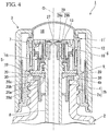
Fig. 4 is a vertical sectional view of main parts of the syringe container shown inFig. 1 , showing a state in which the movable lid portion is closed. -
Fig. 5 is a vertical sectional view of main parts of a syringe container according to a second embodiment of the present invention, showing an initial state. - Hereinafter, a syringe container according to a first embodiment of the present invention will be described with reference to accompanying drawings.
-
Fig. 1 is a vertical sectional view of main parts showing a schematic configuration of a syringe container according to the first embodiment of the present invention, showing an initial state in which the movable lid portion is closed. Asyringe container 1 shown inFig. 1 includes acontainer body 2 that stores contents, and asyringe cap 3 that is mounted to thecontainer body 2 in a freely attachable and detachable manner. - The
container body 2 is formed in a bottomed cylindrical shape, and each central axis of thecontainer body 2 and asyringe tube 8 to be described later of thesyringe cap 3 is disposed on a common axis. Hereinafter, the common axis is defined as a container axis O, a direction along the container axis O is defined as a vertical direction, a bottom side of thecontainer body 2 along the vertical direction is defined as a lower side, and a mouth portion side of thecontainer body 2 as the opposite side thereto is defined as an upper side. In a plan view in which thesyringe container 1 is viewed in the vertical direction, a direction orthogonal to the container axis O is defined as a radial direction, and a direction going around the container axis O is defined as a circumferential direction. - The
container body 2 is provided with aguide cylinder 4 which is fixed by being mounted to themouth portion body 2a which is formed integrally with a body portion or a bottom portion by press-fitting or the like. Thus, themouth portion 2b of thecontainer body 2 is formed to include themouth portion body 2a and theguide cylinder 4. Theguide cylinder 4 includes a cylindricalmain cylinder portion 4a inserted into the upper end portion of themouth portion body 2a, an annular disk-shapedflange portion 4b which extends radially outward from the upper end of themain cylinder portion 4a and locks to an upper end opening edge of themouth portion body 2a, and awiping piece 4c which protrudes radially inward from the inner surface of themain cylinder portion 4a. Thewiping piece 4c vertically and slidably comes into contact with the outer circumferential surface of asyringe tube 8 to be described later to wipe off the contents adhering to the outer circumferential surface of thesyringe tube 8. Thewiping piece 4c is connected to themain cylinder portion 4a via connectingpieces 4d. A plurality of connectingpieces 4d are disposed at intervals in the circumferential direction. Further, theguide cylinder 4 may also be formed integrally with thecontainer body 2. - The
syringe cap 3 includes alid base portion 5 disposed on themouth portion 2b of thecontainer body 2, amovable lid portion 6 which is disposed to be freely movable upward with respect to thelid base portion 5, an urging means 7 which urges thelid base portion 5 and themovable lid portion 6 in a direction of vertically separating thelid base portion 5 and themovable lid portion 6, asyringe tube 8 which is mounted to thelid base portion 5 and extends toward thecontainer body 2, and a packingmember 20. - The
movable lid portion 6 includes a mounting cylinder 9, acylinder portion 10, alid 11, and anexternal cylinder 12. Both of thecylinder portion 10 and thelid 11 are formed in a cylindrical shape. All of the mounting cylinder 9, thecylinder portion 10, thelid 11 and theexternal cylinder 12 are disposed coaxially with the container axis O. - The mounting cylinder 9 is mounted to the
mouth portion body 2a of thecontainer body 2 in a freely attachable and detachable manner. In the present embodiment, alower portion 9a of the mounting cylinder 9 is screwed into themouth portion body 2a from the outside in the radial direction, and anupper portion 9b protrudes upward from themouth portion body 2a. In the lower end portion of the mounting cylinder 9, aflange portion 9c protruding outward in the radial direction is provided. Anengagement cylinder 9d that is disposed coaxially with the container axis O, and surrounds the mounting cylinder 9 from the outside in the radial direction, is erected on theflange portion 9c. - The
cylinder portion 10 is disposed inside the mounting cylinder 9 in the radial direction and is connected to the mounting cylinder 9. Thecylinder portion 10 is disposed in theupper portion 9b of the mounting cylinder 9. Thecylinder portion 10 is formed in a double cylindrical shape, and includes an outercircumferential wall 10a, an innercircumferential wall 10b, and atop wall portion 10c. The outercircumferential wall 10a is formed to have a size equivalent to theupper portion 9b of the mounting cylinder 9 in the vertical direction, and the innercircumferential wall 10b is formed to be smaller than the outercircumferential wall 10a in the vertical direction. Upper end portions of both the outercircumferential wall 10a and the innercircumferential wall 10b are disposed at equivalent positions in the vertical direction. Thetop wall portion 10c is formed in an annular shape coaxial with the container axis O to connect the respective upper end portions of the outercircumferential wall 10a and the innercircumferential wall 10b. - Communication holes 13, which penetrate the
top wall portion 10c in the vertical direction, are formed in thetop wall portion 10c. A plurality of communication holes 13 are provided at intervals in the circumferential direction. The communication holes 13 communicate with the interior of thecylinder portion 10 that is formed by the outercircumferential wall 10a, the innercircumferential wall 10b and thetop wall portion 10c. - An
annular gap 14 is provided between the mounting cylinder 9 and thecylinder portion 10. Theannular gap 14 is formed between theupper portion 9b of the mounting cylinder 9 and the outercircumferential wall 10a of thecylinder portion 10. - The mounting cylinder 9 and the
cylinder portion 10 are connected to each other via theconnection 15. A plurality ofconnections 15 are provided in theannular gap 14 at intervals in the circumferential direction to intermittently connect the lower end portion of theupper portion 9b of the mounting cylinder 9 and the lower end portion of the outercircumferential wall 10a of thecylinder portion 10. Thus, thecylinder portion 10 moves integrally with the mounting cylinder 9. - The
lid 11 is formed to be elastically deformable to close the upper end opening of the mounting cylinder 9. Thelid 11 is formed in a topped cylinder shape (a dome shape), and includes a fittingcylindrical portion 11a, and afilm cylinder portion 11b. The fittingcylindrical portion 11a is air-tightly fitted into the upper end portion of theannular gap 14. Thefilm cylinder portion 11b is formed in a topped cylinder shape, and protrudes upward from the inner circumferential edge of the fittingcylindrical portion 11a, and a top portion thereof is formed in a dome shape. - Between the upper end opening of the mounting cylinder 9 and the
film cylinder portion 11b of thelid 11, aspace 16 that communicates with the interior of thecylinder portion 10 through thecommunication hole 13 is provided. - The
external cylinder 12 is mounted to the mounting cylinder 9 from the outside in the radial direction to be relatively vertically immovable and non-rotatable. Theexternal cylinder 12 is mounted to be vertically immovable, by being undercut-fitted to theflange portion 9c of the mounting cylinder 9.Rotation restricting portions 17 are provided between theexternal cylinder 12 and theengagement cylinder 9d of the mounting cylinder 9, respectively. Therotation restricting portions 17 restrict relative rotational movement between theexternal cylinder 12 and theengagement cylinder 9d in the circumferential direction by engaging with each other. Theexternal cylinder 12 is non-rotatable with respect to the mounting cylinder 9, due to therotation restricting portions 17. - The
external cylinder 12 exposes thelid 11 upward, while interposing its circumferential edge portion in the vertical direction between the mounting cylinder 9 and theexternal cylinder 12. A restrictingring 12a protruding inward in the radial direction is provided at the upper end portion of theexternal cylinder 12, and between the inner circumferential edge portion of the restrictingring 12a and the upper end portion of the mounting cylinder 9, the fittingcylindrical portion 11a of thelid 11 is interposed in the vertical direction. Afilm cylinder portion 11b of thelid 11 is disposed inside the restrictingring 12a, and the top wall portion of thefilm cylinder portion 11b bulges upward from the restrictingring 12a. - The
lid base portion 5 is provided with apiston portion 18 and apiston support portion 19. Further, in this embodiment, a packingmember 20 is mounted to thepiston support portion 19 of thelid base portion 5. Both of thepiston portion 18 and thepiston support portion 19 are formed in a cylindrical shape, and the packingmember 20 is formed in an annular shape. Thepiston portion 18, thepiston support portion 19 and the packingmember 20 are disposed coaxially with the container axis O. - The
piston portion 18 is fitted into thecylinder portion 10 to be freely relatively vertically slidable. Thepiston portion 18 includes an internal cylinder portion 18a, anexternal cylinder portion 18b, abottom wall portion 18c, and aleg cylinder portion 18d. - The internal cylinder portion 18a is fitted to the inner
circumferential wall 10b of thecylinder portion 10 to be freely vertically rotatable from the outer side in the radial direction. Theexternal cylinder portion 18b surrounds the internal cylinder portion 18a from the outer side in the radial direction. Theexternal cylinder portion 18b is smaller than the internal cylinder portion 18a in the vertical direction, and each of the lower end portions of theexternal cylinder portion 18b and the internal cylinder portion 18a are disposed at equivalent positions in the vertical direction. A slidingportion 21 protruding inward in the radial direction is provided at the upper end portion of theexternal cylinder portion 18b. The slidingportion 21 is fitted into the outercircumferential wall 10a of thecylinder portion 10 to be freely vertically slidable. Thebottom wall portion 18c is formed in an annular shape coaxial with the container axis O to connect the respective lower end portions of the internal cylinder portion 18a and theexternal cylinder portion 18b. Theleg cylinder portion 18d extends downward from theexternal cylinder portion 18b. - The
piston support portion 19 includes abase cylinder portion 19a, anannular plate portion 19b, and asubstrate portion 19c. Thebase cylinder portion 19a is fitted into theleg cylinder portion 18d of thepiston portion 18. Theannular plate portion 19b protrudes inward in the radial direction from the upper end portion of thebase cylinder portion 19a. Thesubstrate portion 19c protrudes annularly outward in the radial direction from the lower end portion of thebase cylinder portion 19a. The lower end edge of theleg cylinder portion 18d of thepiston portion 18 is disposed on the upper surface of thesubstrate portion 19c. - An engaging
piece 22 that protrudes upward and enters theannular gap 14 is formed at the outer circumferential edge of thesubstrate portion 19c. A plurality of engagingpieces 22 are disposed at intervals in the circumferential direction, and the engagingpieces 22 adjacent to each other in the circumferential direction interpose theconnections 15 in the circumferential direction. Thus, the relative rotation of thepiston support portion 19 to themovable lid portion 6 is restricted. - The packing
member 20, for example, is formed of a soft material such as rubber or elastomer, and is formed in an annular shape coaxial with the container axis O. The packingmember 20 vertically overlaps thepiston support portion 19, and the upper surface thereof comes into contact with the lower surface of thesubstrate portion 19c and is fixed. Accordingly, the packingmember 20 is disposed between thelid base portion 5 and the upper end opening edge of themouth portion 2b of thecontainer body 2. - In the packing
member 20, anannular protrusion 20a protruding downward is formed on the lower surface thereof, and a crushingprotrusion 20b protruding downward is formed outside theannular protrusion 20a. Further, on the upper surface of the packingmember 20, anoverhang recess 20c is formed so as to be partially located just above the crushingprotrusion 20b. Further, aninner protrusion 20d protruding inward in the radial direction is formed on the inner circumferential surface of the packingmember 20. - The
annular protrusion 20a suppress the crushingprotrusion 20b from being deformed inward in the radial direction, when the crushingprotrusion 20b is relatively pressed against theguide cylinder 4 to be described later. - As shown in
Figs. 3 and4 , the crushingprotrusion 20b is disposed so which a portion located on the outer side in the radial direction comes into contact with the upper end opening edge of theguide cylinder 4. In this embodiment, as shown by the broken line inFig. 2A , the five crushingprotrusions 20b are formed on the inner circumferential edge portion of theannular packing member 20 at equal intervals in the circumferential direction. However, the number of crushingprotrusions 20b is not limited to five, and any number of crushingprotrusions 20b may be formed. Further, in the present embodiment, the thickness of the crushingprotrusion 20b in the vertical direction is thinner than which of theannular protrusion 20a as shown inFigs. 3 and4 . - The
overhang recess 20c is formed so which a portion thereof is located just above the crushingprotrusion 20b and the remaining portions are located just above theannular protrusion 20a as shown inFig. 2A , and as shown inFig. 2B which is a cross-sectional view taken along a line A- A ofFig. 2A , theoverhang recess 20c is formed with a recessed amount (recessed depth) which is substantially equal to the protruding amount (protruding height) of the crushingprotrusion 20b. Such anoverhang recess 20c functions to allow the deformation of the crushingprotrusion 20b or a circumferential edge portion thereof such which the deformation of the crushingprotrusion 20b is not impeded, when the crushingprotrusion 20b is relatively pressed against theguide cylinder 4 and crushed as described later. - Further, in this embodiment, as shown in
Fig. 2A , the crushingprotrusion 20b is longer than theoverhang recess 20c in a radially outward direction, and its width is formed to be wider in the circumferential direction. - The
inner protrusion 20d suppresses the displacement of the packingmember 20 to thesyringe tube 8 side caused when the crushingprotrusion 20b is relatively pressed against theguide cylinder 4 as described later and the pressing force is directed in the radially inward direction of the packingmember 20, by the inner circumferential surface of theinner protrusion 20d coming into contact with the outer circumferential surface of thesyringe tube 8. - The
cylinder portion 10 of themovable lid portion 6 is mounted on thesyringe tube 8 to freely rise, and thesyringe tube 8 is connected to thelid base portion 5. The upper end portion of thesyringe tube 8 is inserted into themovable lid portion 6 and thelid base portion 5. The outer diameter of the upper end portion of thesyringe tube 8 gradually enlarges in a stepwise manner from the upper side toward the lower side, and a small-diameter tube portion 23, a middle-diameter tube portion 24 and a large-diameter tube portion 25 are formed in the upper end portion of thesyringe tube 8. - The small-
diameter tube portion 23 is inserted into the innercircumferential wall 10b of thecylinder portion 10 to be freely vertically movable. In the middle-diameter tube portion 24, afitting groove 24a to which theannular plate portion 19b of thepiston support portion 19 is fitted is circumferentially provided. The large-diameter tube portion 25 is fitted into thebase cylinder portion 19a of thelid base portion 5, and is located just above the packingmember 20. In the large-diameter tube portion 25, aring holding groove 25a to which an O-ring 26 is fitted is circumferentially provided. The O-ring 26 forms an airtight seal between the large-diameter tube portion 25 and thebase cylinder portion 19a. - Further, in the shown example, in the inner
circumferential wall 10b of thecylinder portion 10, avalve body 27 that closes the upper end opening of thesyringe tube 8 in a freely opening and closing manner is provided. Thevalve body 27 is disposed on the container axis O, and is connected to the upper end portion of the innercircumferential wall 10b of thecylinder portion 10 viabridge portions 28. A plurality ofbridge portions 28 are disposed at intervals in the circumferential direction. When themovable lid portion 6 rises to thesyringe tube 8, and the upper end opening of thesyringe tube 8 is opened by thevalve body 27, the interior of thesyringe tube 8 communicates with thespace 16. That is, the interior of thesyringe tube 8 can communicate with thespace 16. - The
syringe tube 8 and thecylinder portion 10 are formed with engagingportions 29 which engage with each other when thecylinder portion 10 is located at the rising end position to thesyringe tube 8. As the engagingportion 29, an outerengaging portion 29a provided in thecylinder portion 10, and an innerengaging portion 29b provided on thesyringe tube 8 are provided. The outerengaging portion 29a annularly protrudes inward in the radial direction from the lower end of the innercircumferential wall 10b of thecylinder portion 10, and the inner engagingportion 29b annularly protrudes outward in the radial direction from the upper end of the small-diameter tube portion 23 of thesyringe tube 8. The outerengaging portion 29a faces the inner engagingportion 29b from the lower part, and when thecylinder portion 10 rises to thesyringe tube 8, the outer engagingportion 29a engages with the inner engagingportion 29b from the lower part, thereby restricting further rising movement of thecylinder portion 10. - The urging means 7 is disposed between the
cylinder portion 10 of themovable lid portion 6 and thepiston portion 18 of thelid base portion 5. The urging means 7 is supported by thetop wall portion 10c of thecylinder portion 10 from the upper part, and is supported on thebottom wall portion 18c of thepiston portion 18 from the lower part. The urging means 7 is formed in a cylindrical shape, and is disposed coaxially with the container axis O. As the urging means 7, for example, a coil spring or the like can be adopted. - In the
syringe container 1, as shown inFig. 1 , in the initial state in which thesyringe cap 3 is mounted to thecontainer body 2, the packingmember 20 is pressed against theflange portion 4b of theguide cylinder 4 in themouth portion 2b of thecontainer body 2. That is, the packingmember 20 is sandwiched between thelid base portion 5 and the upper end opening edge of themouth portion body 2a of thecontainer body 2 via theflange portion 4b. At this time, when the packingmember 20 is pressed against theflange portion 4b, the crushingprotrusion 20b is crushed to an upper end opening edge of themouth portion 2b. Thus, the packingmember 20 comes into contact with theflange portion 4b without a clearance to provide a good seal between thelid base portion 5 and theflange portion 4b, i.e., between thelid base portion 5 and the upper end opening edge of themouth portion 2b of thecontainer body 2, thereby air-tightly closing themouth portion 2b. - Further, by forming the
overhang recess 20c just above the crushingprotrusion 20b, the elastic deformation of the packingmember 20 caused by crushing of the crushingprotrusion 20b is allowed without impeding the elastic deformation, and the elastic deformation easily occurs. - Next, the operation of the syringe container will be described.
- When spouting the contents, first, in order to disengage the
syringe cap 3 from thecontainer body 2, the screwing between the mounting cylinder 9 of themovable lid portion 6 and themouth portion body 2a of thecontainer body 2 is released, and themovable lid portion 6 is raised with respect to thecontainer body 2. At this time, when theexternal cylinder 12 of themovable lid portion 6 is rotated to the loosened side around the container axis O with respect to thecontainer body 2, the rotational force is transmitted to the mounting cylinder 9 via therotation restricting portion 17 and theengagement cylinder 9d, the mounting cylinder 9 rotates with theexternal cylinder 12, and the entiremovable lid portion 6 rotates. Furthermore, in this embodiment, when theconnection 15 of themovable lid portion 6 engages with the engagingpiece 22 of thesubstrate portion 19c at this time, thelid base portion 5 also rotates with themovable lid portion 6. - When rotating the
movable lid portion 6 to the loosened side around the container axis O and raising themovable lid portion 6 with respect to thecontainer body 2, due to the urging force of the urging means 7, thepiston portion 18 of thelid base portion 5 slides relatively downward inside thecylinder portion 10 of themovable lid portion 6, the internal volume of thecylinder portion 10 increases, and thevalve body 27 opens the upper end opening of thesyringe tube 8, while a negative pressure is generated in thecylinder portion 10. The negative pressure generated in thecylinder portion 10 is exerted on thecontainer body 2 through thecommunication hole 13, thespace 16 and thesyringe tube 8, and the contents of thecontainer body 2 are sucked into thesyringe tube 8. - As shown in
Fig. 3 , themovable lid portion 6 rises to a rising end position with respect to thesyringe tube 8, and the engaging portions 29 (the outer engagingportions 29a, and the inner engagingportions 29b) are engaged with each other. After that, when themovable lid portion 6 is further raised to thecontainer body 2, themovable lid portion 6 and thesyringe tube 8 rise together via the engagingportion 29. Thus, thesyringe tube 8 is extracted from thecontainer body 2, and thesyringe cap 3 is detached from thecontainer body 2. At this time, because the pressing force of the packingmember 20 to the crushingprotrusion 20b is released, the crushingprotrusion 20b is restored and deformed into a protruding shape. - Further, by pressing the
film cylinder portion 11b of thelid 11 in thesyringe cap 3 that is detached from thecontainer body 2, the contents of thesyringe tube 8 are spouted from the lower end opening of thesyringe tube 8. - When the
syringe cap 3 detached from thecontainer body 2 is mounted again, by inserting thesyringe tube 8 into themouth portion 2b of thecontainer body 2 via themovable lid portion 6, and for example, by rotating theexternal cylinder 12 to the tightened side around the container axis O to thecontainer body 2 to screw the mounting cylinder 9 to themouth portion body 2a, themovable lid portion 6 is lowered to thecontainer body 2. - At this time, when inserting the
syringe tube 8 into themouth portion 2b of thecontainer body 2, as shown inFig. 3 , the packingmember 20 below thelid base portion 5 is placed on theflange portion 4b of theguide cylinder 4. However, since the pressing force of lowering thelid base portion 5 is hardly applied, the packingmember 20 maintains a protruding state without crushing of the crushingprotrusion 20b. Thus, acommunication gap 30 is formed between the packingmember 20 and theflange portion 4b. - Further, when the
movable lid portion 6 is lowered to thecontainer body 2 from the state shown inFig. 3 as shown inFig. 4 , thecylinder portion 10 is lowered against the urging force of the urging means 7, and thelid base portion 5 is also pressed downward accordingly. Then, the pressing force of lowering thelid base portion 5 acts on the packingmember 20, and the crushingprotrusion 20b of the packingmember 20 is gradually crushed. However, until the crushingprotrusion 20b is sufficiently crushed, thecommunication gap 30 between the packingmember 20 and theflange portion 4b is ensured without being closed. - When the
movable lid portion 6 is lowered to thelid base portion 5 to reach the state shown inFig. 4 from the state shown inFig. 3 , thepiston portion 18 of thelid base portion 5 slides relatively upward inside thecylinder portion 10 of themovable lid portion 6 to reduce the internal volume of thecylinder portion 10 and generate a positive pressure in thecylinder portion 10. The positive pressure is exerted on the interior of thecontainer body 2 via thecommunication hole 13, thespace 16 and thesyringe tube 8. At this time, since the interior of thecontainer body 2 communicates with the exterior through thecommunication gap 30, the positive pressure exerted on the interior of thecontainer body 2 is released to the exterior through thecommunication gap 30, and the internal pressure rise in thecontainer body 2 is suppressed. - After that, by further lowering the
movable lid portion 6, thesyringe cap 3 is lowered to thecontainer body 2. Thus, as shown inFig. 1 , thelid base portion 5 presses the packingmember 20 to crush the crushingprotrusion 20b, and closes thecommunication gap 30 between the packingmember 20 and theflange portion 4b. Thus, sealing properties between the packingmember 20 and theflange portion 4b are ensured. - When spouting the contents again, the screwing of the mounting cylinder 9 to the
mouth portion body 2a is released again, and themovable lid portion 6 is raised to thecontainer body 2. Since the internal pressure rise in thecontainer body 2 is suppressed at the time of the previous spouting operation, when a negative pressure is generated in thecylinder portion 10 at the time of the present spouting operation, a certain amount of contents of thecontainer body 2 is accurately sucked into thesyringe tube 8. If the positive pressure generated in thecylinder portion 10 at the time of the previous spouting operation is not released to the exterior, the degree of increase in internal pressure of thecontainer body 2 based on the positive pressure changes according to the remaining amount of the contents. Accordingly, when a negative pressure is generated in thecylinder portion 10 at the time of the present spouting operation, even if the magnitude of the negative pressure is the same, there is a possibility of change in the suction amount of the contents to thesyringe tube 8. - As described above, according to the
syringe container 1 of the present embodiment, when themovable lid portion 6 is lowered to thelid base portion 5, the positive pressure generated in thecylinder portion 10 is released to the exterior through thecommunication gap 30 formed by the crushingprotrusion 20b of the packingmember 20, thereby making it possible to suppress an increase in internal pressure of thecontainer body 2. Therefore, it is possible to keep the suction amount constant with high precision, regardless of the remaining amount of the contents. - Further, when the mounting cylinder 9 rotates about the container axis O, the
lid base portion 5 engages with theconnection 15 and rotates with themovable lid portion 6. Accordingly, when the mounting cylinder 9 is attached to or detached from themouth portion 2b of thecontainer body 2, it is also possible to rotate thelid base portion 5 as well as themovable lid portion 6. Accordingly, it is possible to allow thepiston portion 18 to smoothly slide vertically inside thecylinder portion 10. - Further, the
external cylinder 12 exposes thelid 11 upward, while interposing the circumferential edge portion thereof in the vertical direction between the mounting cylinder 9 and theexternal cylinder 12. Therefore, it is possible to firmly fix thelid 11 to the mounting cylinder 9, without impeding the pressing operation of thelid 11. - Further, in the present embodiment, the
valve body 27 closes the upper opening of thesyringe tube 8 in the initial state. Thus, for example, even when unintentionally operating thelid 11 in the initial state, it is possible to suppress the contents in thecontainer body 2 from accidentally flowing into thesyringe tube 8. Therefore, it is possible to keep the spouting amount of contents from thesyringe tube 8 constant with high accuracy. Further, for example, even if the contents of thecontainer body 2 flow into thesyringe tube 8 due to the turnover of thesyringe container 1 in the initial state, it is possible to block the contents by thevalve body 27. Therefore, it is also possible to restrict the contents from flowing into thespace 16. - Next, a syringe container according to a second embodiment of the present invention will be described.
- In the second embodiment, the same components as the in the first embodiment are denoted by the same reference numerals, the description thereof will not be provided, and only differences will be described.
- As shown in
Fig. 5 , in thesyringe container 40 of the present embodiment, in addition to the configuration shown inFigs. 1 and2 , the packingmember 41 forms a lockingprotrusion 42 in the outer circumferential edge portion. The lockingprotrusion 42 is formed in a cylindrical shape in this embodiment, and engages with the outer circumferential surface of the upper end opening portion of themouth portion 2b of thecontainer body 2, i.e., the outer circumferential surface of theflange portion 4b of theguide cylinder 4 in an engageable and disengageable manner. However, the lockingprotrusion 42 may not be formed in a cylindrical shape, and a plurality of protruding pieces may be disposed and formed on the outer circumference at predetermined intervals. - By including the packing
member 41 formed with such alocking protrusion 42, in thesyringe container 40 of the present embodiment, after spouting the contents from thesyringe tube 8, when themovable lid portion 6 is mounted to thecontainer body 2 again, and themovable lid portion 6 is lowered, the displacement of the packingmember 41 to the interior of thecontainer body 2 caused by being crushed between thelid base portion 5 and the upper end opening edge of themouth portion 2b of thecontainer body 2 is suppressed by the lockingprotrusion 42 which engages with the outer circumferential surface (the outer circumferential surface of theflange portion 4b of the guide cylinder 4) of the upper end opening portion of thecontainer body 2. - Therefore, in the
syringe container 40 of the present embodiment, it is possible to satisfactorily ensure the sealing properties of the packingmember 41, and it is possible to suppress the deformation and deterioration of the packingmember 41 associated with the long period of use. Further, as in the first embodiment, when themovable lid portion 6 is lowered to thelid base portion 5, because the positive pressure generated in thecylinder portion 10 is released to the exterior and an internal pressure rise in thecontainer body 2 can be suppressed, it is possible to keep the suction amount constant with high precision, regardless of the remaining amount of the contents. - The technical scope of the present invention is not limited to the above embodiments, and it is possible to apply various changes without departing from the gist of the present invention.
- For example, the mounting cylinder 9 may not be screwed to the
mouth portion body 2a of thecontainer body 2. That is, the present invention can be appropriately changed to another form in which the mounting cylinder 9 is mounted on themouth portion 2b in a freely attachable and detachable manner - According to the present invention, it is possible to provide a syringe container in which the suction amount is kept constant with high precision, regardless of the remaining amount of the contents.
-
- 1 Syringe container
- 2 Container body
- 2b Mouth portion
- 5 Lid base portion
- 6 Movable lid portion
- 7 Urging means
- 8 Syringe tube
- 9 Mounting cylinder
- 10 Cylinder portion
- 11 Lid
- 12 External cylinder
- 13 Communication hole
- 15 Connection
- 16 Space
- 18 Piston portion
- 20 Packing member
- 20b Crushing protrusion
- 20c Overhang recess
- 29 Engaging portion
- 40 Syringe container
- 41 Packing member
- 42 Locking protrusion
- O Container axis
Claims (11)
- A syringe container (1) comprising:a container body (2) which stores contents;a lid base portion (5) which is disposed on an upper end opening edge of a mouth portion (2b) of the container body (2);a movable lid portion (6) which is disposed to freely move upward and downward relative to the lid base portion (5);an urging means (7) which urges the lid base portion (5) and the movable lid portion (6) in a vertically separating direction; anda syringe tube (8) which is mounted on the lid base portion (5) and extends toward the container body (2);the mouth portion (2b) including:a mouth portion body (2a), anda guide cylinder (4) fixed by being mounted to the mouth portion body (2a);the movable lid portion (6) including:a mounting cylinder (9), a lower portion (9a) which is mounted on the mouth portion body (2a) in a freely attachable and detachable manner from an outside in the radial direction,a lid (11) which is formed to be elastically deformable and closes an upper end opening of the mounting cylinder (9), anda cylinder portion (10) which is disposed inside the mounting cylinder (9) in a radial direction and is connected to the mounting cylinder (9);the lid base portion (5) including a piston portion (18) which is connected to the syringe tube (8) and is fitted to the inside of the cylinder portion (10) to freely slide up and down;the cylinder portion (10) being mounted on the syringe tube (8) to freely rise, and the cylinder portion (10) and the syringe tube (8) being formed with engaging portions (29) which engage with each other when the cylinder portion (10) is located at a rising end position with respect to the syringe tube (8);the interior of the syringe tube (8) communicating with a space between the upper end opening of the mounting cylinder (9) and the lid (11);the cylinder portion (10) being formed with a communication hole (13) through which the interior and the space communicate with each other;wherein a packing member (20) is disposed between the lid base portion (5) and the upper end opening edge of the mouth portion (2b) of the container body (2), andcharacterized in thatthe guide cylinder (4) includes:a cylindrical main cylinder portion (4a) inserted into the upper end portion of the mouth portion body (2a), andan annular disk-shaped flange portion (4b) which extends radially outward from the upper end of the main cylinder portion (4a) and locks to the upper end opening edge of the mouth portion body (2a), anda wiping piece (4c) which protrudes radially inward from the inner surface of the main cylinder portion (4a) and vertically and slidably comes into contact with the outer circumferential surface of the syringe tube (8), anda crushing protrusion (20b) is formed on the lower surface of the packing member (20), the crushing protrusion (20b) protruding downward and adapted to press against and be crushed to the flange portion (4b) of the guide cylinder (4), and an overhang recess (20c) is formed on the upper surface of the packing member (20), the overhang recess (20c) being at least partially located just above the crushing protrusion (20).
- The syringe container (1) according to claim 1, wherein the packing member (20) is formed with a locking protrusion (42) adapted to be locked with the outer circumferential surface of the flange portion (4b) of the guide cylinder (4).
- The syringe container (1) according to claim 1, wherein the mounting cylinder (9) is screwed into the mouth portion body (2a) of the mouth portion (2b), and is connected to the cylinder portion (10) via a connection (15), and the lid base portion (5) engages with the connection (15) when the mounting cylinder (9) rotates about the container axis (O), and rotates with the movable lid portion (6).
- The syringe container (1) according to claim 2, wherein the mounting cylinder (9) is is screwed into the mouth portion body (2a) of the mouth portion (2b), and is connected to the cylinder portion (10) via a connection (15), and the lid base portion (5) engages with the connection (15) when the mounting cylinder (9) rotates about the container axis (O), and rotates with the movable lid portion (6).
- The syringe container (1) according to claim 1, wherein the movable lid portion (6) comprises an external cylinder (12) which is mounted on the mounting cylinder (9) to be relatively vertically immovable and non-rotatable from the outside in the radial direction, and the external cylinder (12) exposes the lid (11) upward, while interposing a circumferential edge portion of the lid (11) in the vertical direction between the mounting cylinder (9) and the external cylinder (12).
- The syringe container (1) according to claim 2, wherein the movable lid portion (6) comprises an external cylinder (12) which is mounted on the mounting cylinder (9) to be relatively vertically immovable and non-rotatable from the outside in the radial direction, and the external cylinder (12) exposes the lid (11) upward, while interposing a circumferential edge portion of the lid (11) in the vertical direction between the mounting cylinder (9) and the external cylinder (12).
- The syringe container (1) according to claim 3, wherein the movable lid portion (6) comprises an external cylinder (12) which is mounted on the mounting cylinder (9) to be relatively vertically immovable and non-rotatable from the outside in the radial direction, and the external cylinder (12) exposes the lid (11) upward, while interposing a circumferential edge portion of the lid (11) in the vertical direction between the mounting cylinder (9) and the external cylinder (12).
- The syringe container (1) according to claim 4, wherein the movable lid portion (6) comprises an external cylinder (12) which is mounted on the mounting cylinder (9) to be relatively vertically immovable and non-rotatable from the outside in the radial direction, and the external cylinder (12) exposes the lid (11) upward, while interposing a circumferential edge portion of the lid (11) in the vertical direction between the mounting cylinder (9) and the external cylinder (12).
- The syringe container (1) according to claim 1, wherein the packing member (20) is an annular packing member, and the crushing protrusion (20b) is a plurality of crushing protrusions (20b) which are formed on an inner circumferential edge portion of the annular packing member at equal intervals in a circumferential direction.
- The syringe container (1) according to claim 1, wherein the packing member (20) is an annular packing member, and the crushing protrusion (20b) is formed to be longer than the overhang recess (20c) outward in the radial direction and to be wider in a circumferential direction.
- The syringe container (1) according to claim 1, wherein a recessed amount of the overhang recess (20c) is substantially equal to the protruding amount of the crushing protrusion (20b).
Applications Claiming Priority (2)
| Application Number | Priority Date | Filing Date | Title |
|---|---|---|---|
| JP2014223599A JP6379011B2 (en) | 2014-10-31 | 2014-10-31 | Dropper container |
| PCT/JP2015/072406 WO2016067705A1 (en) | 2014-10-31 | 2015-08-06 | Syringe container |
Publications (3)
| Publication Number | Publication Date |
|---|---|
| EP3214014A1 EP3214014A1 (en) | 2017-09-06 |
| EP3214014A4 EP3214014A4 (en) | 2018-06-13 |
| EP3214014B1 true EP3214014B1 (en) | 2019-12-04 |
Family
ID=55857052
Family Applications (1)
| Application Number | Title | Priority Date | Filing Date |
|---|---|---|---|
| EP15854713.3A Active EP3214014B1 (en) | 2014-10-31 | 2015-08-06 | Syringe container |
Country Status (6)
| Country | Link |
|---|---|
| US (1) | US10143623B2 (en) |
| EP (1) | EP3214014B1 (en) |
| JP (1) | JP6379011B2 (en) |
| KR (1) | KR102271121B1 (en) |
| CN (1) | CN106794928B (en) |
| WO (1) | WO2016067705A1 (en) |
Families Citing this family (5)
| Publication number | Priority date | Publication date | Assignee | Title |
|---|---|---|---|---|
| JP6917940B2 (en) * | 2018-03-29 | 2021-08-11 | 太平洋工業株式会社 | Valve cap and valve with cap |
| WO2021046002A1 (en) * | 2019-09-02 | 2021-03-11 | The Procter & Gamble Company | Dispenser for viscous products |
| JP7313248B2 (en) * | 2019-09-30 | 2023-07-24 | 株式会社吉野工業所 | dropper container |
| CN110934410B (en) * | 2019-11-29 | 2022-06-14 | 上海容奥包装科技有限公司 | Mascara device |
| CN117729975A (en) * | 2021-07-27 | 2024-03-19 | 宝洁公司 | Dispenser for viscous products |
Family Cites Families (11)
| Publication number | Priority date | Publication date | Assignee | Title |
|---|---|---|---|---|
| JPH0642735Y2 (en) | 1989-03-17 | 1994-11-09 | 株式会社吉野工業所 | Container with dropper |
| JPH0752056Y2 (en) * | 1989-04-06 | 1995-11-29 | 釜屋化学工業株式会社 | Container with dropper |
| JPH0642735A (en) | 1992-07-24 | 1994-02-18 | Mitsubishi Heavy Ind Ltd | Gas turbine combined facility |
| JP3291531B2 (en) * | 1993-07-02 | 2002-06-10 | 三洋化学工業株式会社 | Inside cap |
| JPH0717757U (en) * | 1993-08-31 | 1995-03-31 | 株式会社吉野工業所 | Container with dropper |
| JP2549350Y2 (en) * | 1993-10-15 | 1997-09-30 | 鐘紡株式会社 | Dropper container |
| JP3387649B2 (en) * | 1994-09-16 | 2003-03-17 | 富士写真フイルム株式会社 | Spotted tip |
| JP4251340B2 (en) * | 1998-09-25 | 2009-04-08 | 株式会社資生堂 | Cap with dropper |
| US8403008B2 (en) * | 2010-05-24 | 2013-03-26 | Elc Management, Llc | Metered dose applicator with light for activating product |
| BR112012031132B1 (en) * | 2010-06-07 | 2019-08-06 | L'oreal | PACKING AND DISTRIBUTING DEVICE |
| KR200453126Y1 (en) * | 2010-07-23 | 2011-04-13 | 주식회사 에프에스코리아 | Eyedropper Cosmetic Container |
-
2014
- 2014-10-31 JP JP2014223599A patent/JP6379011B2/en active Active
-
2015
- 2015-08-06 KR KR1020177004361A patent/KR102271121B1/en active IP Right Grant
- 2015-08-06 EP EP15854713.3A patent/EP3214014B1/en active Active
- 2015-08-06 WO PCT/JP2015/072406 patent/WO2016067705A1/en active Application Filing
- 2015-08-06 US US15/328,826 patent/US10143623B2/en active Active
- 2015-08-06 CN CN201580046182.9A patent/CN106794928B/en active Active
Non-Patent Citations (1)
| Title |
|---|
| None * |
Also Published As
| Publication number | Publication date |
|---|---|
| US10143623B2 (en) | 2018-12-04 |
| CN106794928A (en) | 2017-05-31 |
| KR20170078588A (en) | 2017-07-07 |
| EP3214014A1 (en) | 2017-09-06 |
| CN106794928B (en) | 2018-08-24 |
| WO2016067705A1 (en) | 2016-05-06 |
| JP2016088556A (en) | 2016-05-23 |
| JP6379011B2 (en) | 2018-08-22 |
| EP3214014A4 (en) | 2018-06-13 |
| US20170216141A1 (en) | 2017-08-03 |
| KR102271121B1 (en) | 2021-07-01 |
Similar Documents
| Publication | Publication Date | Title |
|---|---|---|
| EP3214014B1 (en) | Syringe container | |
| EP3480130A1 (en) | Discharge container | |
| WO2015175716A1 (en) | Mechanically sealed container cap | |
| CN105916591B (en) | Fluid reservoir and dispenser comprising such a reservoir | |
| CN105711949A (en) | System for actuating member for dispensing fluid product | |
| JP6335756B2 (en) | Dropper container | |
| JP2015224071A (en) | Syringe container | |
| JP5311475B2 (en) | Liquid discharge pump | |
| JP2016087513A (en) | Syringe container | |
| JP7250492B2 (en) | mixing container | |
| JP7486456B2 (en) | Dropper container | |
| JP7399016B2 (en) | dropper container | |
| JP7321616B1 (en) | Containers with Lids and Lid Units | |
| WO2015152259A1 (en) | Dropper container | |
| JP2019177940A (en) | Pump mechanism and discharger | |
| JP3238239U (en) | Container lid device | |
| JP7158253B2 (en) | ejector | |
| JP5993795B2 (en) | Discharge container | |
| JP7386696B2 (en) | foam dispenser | |
| JP2024041402A (en) | dropper container | |
| JP2019508330A (en) | Fluid product dispenser | |
| JP6920951B2 (en) | Discharger | |
| JP6007019B2 (en) | Discharge container | |
| JP2016222291A (en) | Syringe type container | |
| JP2024033938A (en) | dropper container |
Legal Events
| Date | Code | Title | Description |
|---|---|---|---|
| STAA | Information on the status of an ep patent application or granted ep patent |
Free format text: STATUS: THE INTERNATIONAL PUBLICATION HAS BEEN MADE |
|
| PUAI | Public reference made under article 153(3) epc to a published international application that has entered the european phase |
Free format text: ORIGINAL CODE: 0009012 |
|
| STAA | Information on the status of an ep patent application or granted ep patent |
Free format text: STATUS: REQUEST FOR EXAMINATION WAS MADE |
|
| 17P | Request for examination filed |
Effective date: 20170531 |
|
| AK | Designated contracting states |
Kind code of ref document: A1 Designated state(s): AL AT BE BG CH CY CZ DE DK EE ES FI FR GB GR HR HU IE IS IT LI LT LU LV MC MK MT NL NO PL PT RO RS SE SI SK SM TR |
|
| AX | Request for extension of the european patent |
Extension state: BA ME |
|
| DAV | Request for validation of the european patent (deleted) | ||
| DAX | Request for extension of the european patent (deleted) | ||
| A4 | Supplementary search report drawn up and despatched |
Effective date: 20180511 |
|
| RIC1 | Information provided on ipc code assigned before grant |
Ipc: B01L 3/02 20060101ALI20180504BHEP Ipc: A61J 1/20 20060101ALI20180504BHEP Ipc: B65D 53/02 20060101ALI20180504BHEP Ipc: B65D 51/32 20060101AFI20180504BHEP |
|
| STAA | Information on the status of an ep patent application or granted ep patent |
Free format text: STATUS: EXAMINATION IS IN PROGRESS |
|
| 17Q | First examination report despatched |
Effective date: 20190131 |
|
| GRAP | Despatch of communication of intention to grant a patent |
Free format text: ORIGINAL CODE: EPIDOSNIGR1 |
|
| STAA | Information on the status of an ep patent application or granted ep patent |
Free format text: STATUS: GRANT OF PATENT IS INTENDED |
|
| INTG | Intention to grant announced |
Effective date: 20190826 |
|
| GRAS | Grant fee paid |
Free format text: ORIGINAL CODE: EPIDOSNIGR3 |
|
| GRAA | (expected) grant |
Free format text: ORIGINAL CODE: 0009210 |
|
| STAA | Information on the status of an ep patent application or granted ep patent |
Free format text: STATUS: THE PATENT HAS BEEN GRANTED |
|
| AK | Designated contracting states |
Kind code of ref document: B1 Designated state(s): AL AT BE BG CH CY CZ DE DK EE ES FI FR GB GR HR HU IE IS IT LI LT LU LV MC MK MT NL NO PL PT RO RS SE SI SK SM TR |
|
| REG | Reference to a national code |
Ref country code: GB Ref legal event code: FG4D |
|
| REG | Reference to a national code |
Ref country code: CH Ref legal event code: EP |
|
| REG | Reference to a national code |
Ref country code: AT Ref legal event code: REF Ref document number: 1209117 Country of ref document: AT Kind code of ref document: T Effective date: 20191215 |
|
| REG | Reference to a national code |
Ref country code: DE Ref legal event code: R096 Ref document number: 602015043208 Country of ref document: DE |
|
| REG | Reference to a national code |
Ref country code: IE Ref legal event code: FG4D |
|
| REG | Reference to a national code |
Ref country code: NL Ref legal event code: MP Effective date: 20191204 |
|
| REG | Reference to a national code |
Ref country code: LT Ref legal event code: MG4D |
|
| PG25 | Lapsed in a contracting state [announced via postgrant information from national office to epo] |
Ref country code: SE Free format text: LAPSE BECAUSE OF FAILURE TO SUBMIT A TRANSLATION OF THE DESCRIPTION OR TO PAY THE FEE WITHIN THE PRESCRIBED TIME-LIMIT Effective date: 20191204 Ref country code: LV Free format text: LAPSE BECAUSE OF FAILURE TO SUBMIT A TRANSLATION OF THE DESCRIPTION OR TO PAY THE FEE WITHIN THE PRESCRIBED TIME-LIMIT Effective date: 20191204 Ref country code: FI Free format text: LAPSE BECAUSE OF FAILURE TO SUBMIT A TRANSLATION OF THE DESCRIPTION OR TO PAY THE FEE WITHIN THE PRESCRIBED TIME-LIMIT Effective date: 20191204 Ref country code: BG Free format text: LAPSE BECAUSE OF FAILURE TO SUBMIT A TRANSLATION OF THE DESCRIPTION OR TO PAY THE FEE WITHIN THE PRESCRIBED TIME-LIMIT Effective date: 20200304 Ref country code: GR Free format text: LAPSE BECAUSE OF FAILURE TO SUBMIT A TRANSLATION OF THE DESCRIPTION OR TO PAY THE FEE WITHIN THE PRESCRIBED TIME-LIMIT Effective date: 20200305 Ref country code: NO Free format text: LAPSE BECAUSE OF FAILURE TO SUBMIT A TRANSLATION OF THE DESCRIPTION OR TO PAY THE FEE WITHIN THE PRESCRIBED TIME-LIMIT Effective date: 20200304 Ref country code: LT Free format text: LAPSE BECAUSE OF FAILURE TO SUBMIT A TRANSLATION OF THE DESCRIPTION OR TO PAY THE FEE WITHIN THE PRESCRIBED TIME-LIMIT Effective date: 20191204 |
|
| PG25 | Lapsed in a contracting state [announced via postgrant information from national office to epo] |
Ref country code: HR Free format text: LAPSE BECAUSE OF FAILURE TO SUBMIT A TRANSLATION OF THE DESCRIPTION OR TO PAY THE FEE WITHIN THE PRESCRIBED TIME-LIMIT Effective date: 20191204 Ref country code: RS Free format text: LAPSE BECAUSE OF FAILURE TO SUBMIT A TRANSLATION OF THE DESCRIPTION OR TO PAY THE FEE WITHIN THE PRESCRIBED TIME-LIMIT Effective date: 20191204 |
|
| PG25 | Lapsed in a contracting state [announced via postgrant information from national office to epo] |
Ref country code: AL Free format text: LAPSE BECAUSE OF FAILURE TO SUBMIT A TRANSLATION OF THE DESCRIPTION OR TO PAY THE FEE WITHIN THE PRESCRIBED TIME-LIMIT Effective date: 20191204 |
|
| PG25 | Lapsed in a contracting state [announced via postgrant information from national office to epo] |
Ref country code: EE Free format text: LAPSE BECAUSE OF FAILURE TO SUBMIT A TRANSLATION OF THE DESCRIPTION OR TO PAY THE FEE WITHIN THE PRESCRIBED TIME-LIMIT Effective date: 20191204 Ref country code: CZ Free format text: LAPSE BECAUSE OF FAILURE TO SUBMIT A TRANSLATION OF THE DESCRIPTION OR TO PAY THE FEE WITHIN THE PRESCRIBED TIME-LIMIT Effective date: 20191204 Ref country code: NL Free format text: LAPSE BECAUSE OF FAILURE TO SUBMIT A TRANSLATION OF THE DESCRIPTION OR TO PAY THE FEE WITHIN THE PRESCRIBED TIME-LIMIT Effective date: 20191204 Ref country code: RO Free format text: LAPSE BECAUSE OF FAILURE TO SUBMIT A TRANSLATION OF THE DESCRIPTION OR TO PAY THE FEE WITHIN THE PRESCRIBED TIME-LIMIT Effective date: 20191204 Ref country code: ES Free format text: LAPSE BECAUSE OF FAILURE TO SUBMIT A TRANSLATION OF THE DESCRIPTION OR TO PAY THE FEE WITHIN THE PRESCRIBED TIME-LIMIT Effective date: 20191204 Ref country code: PT Free format text: LAPSE BECAUSE OF FAILURE TO SUBMIT A TRANSLATION OF THE DESCRIPTION OR TO PAY THE FEE WITHIN THE PRESCRIBED TIME-LIMIT Effective date: 20200429 |
|
| PG25 | Lapsed in a contracting state [announced via postgrant information from national office to epo] |
Ref country code: SM Free format text: LAPSE BECAUSE OF FAILURE TO SUBMIT A TRANSLATION OF THE DESCRIPTION OR TO PAY THE FEE WITHIN THE PRESCRIBED TIME-LIMIT Effective date: 20191204 Ref country code: IS Free format text: LAPSE BECAUSE OF FAILURE TO SUBMIT A TRANSLATION OF THE DESCRIPTION OR TO PAY THE FEE WITHIN THE PRESCRIBED TIME-LIMIT Effective date: 20200404 Ref country code: SK Free format text: LAPSE BECAUSE OF FAILURE TO SUBMIT A TRANSLATION OF THE DESCRIPTION OR TO PAY THE FEE WITHIN THE PRESCRIBED TIME-LIMIT Effective date: 20191204 |
|
| REG | Reference to a national code |
Ref country code: DE Ref legal event code: R097 Ref document number: 602015043208 Country of ref document: DE |
|
| REG | Reference to a national code |
Ref country code: AT Ref legal event code: MK05 Ref document number: 1209117 Country of ref document: AT Kind code of ref document: T Effective date: 20191204 |
|
| PLBE | No opposition filed within time limit |
Free format text: ORIGINAL CODE: 0009261 |
|
| STAA | Information on the status of an ep patent application or granted ep patent |
Free format text: STATUS: NO OPPOSITION FILED WITHIN TIME LIMIT |
|
| PG25 | Lapsed in a contracting state [announced via postgrant information from national office to epo] |
Ref country code: DK Free format text: LAPSE BECAUSE OF FAILURE TO SUBMIT A TRANSLATION OF THE DESCRIPTION OR TO PAY THE FEE WITHIN THE PRESCRIBED TIME-LIMIT Effective date: 20191204 |
|
| 26N | No opposition filed |
Effective date: 20200907 |
|
| PG25 | Lapsed in a contracting state [announced via postgrant information from national office to epo] |
Ref country code: SI Free format text: LAPSE BECAUSE OF FAILURE TO SUBMIT A TRANSLATION OF THE DESCRIPTION OR TO PAY THE FEE WITHIN THE PRESCRIBED TIME-LIMIT Effective date: 20191204 Ref country code: AT Free format text: LAPSE BECAUSE OF FAILURE TO SUBMIT A TRANSLATION OF THE DESCRIPTION OR TO PAY THE FEE WITHIN THE PRESCRIBED TIME-LIMIT Effective date: 20191204 Ref country code: PL Free format text: LAPSE BECAUSE OF FAILURE TO SUBMIT A TRANSLATION OF THE DESCRIPTION OR TO PAY THE FEE WITHIN THE PRESCRIBED TIME-LIMIT Effective date: 20191204 |
|
| PG25 | Lapsed in a contracting state [announced via postgrant information from national office to epo] |
Ref country code: IT Free format text: LAPSE BECAUSE OF FAILURE TO SUBMIT A TRANSLATION OF THE DESCRIPTION OR TO PAY THE FEE WITHIN THE PRESCRIBED TIME-LIMIT Effective date: 20191204 |
|
| PG25 | Lapsed in a contracting state [announced via postgrant information from national office to epo] |
Ref country code: MC Free format text: LAPSE BECAUSE OF FAILURE TO SUBMIT A TRANSLATION OF THE DESCRIPTION OR TO PAY THE FEE WITHIN THE PRESCRIBED TIME-LIMIT Effective date: 20191204 |
|
| REG | Reference to a national code |
Ref country code: CH Ref legal event code: PL |
|
| PG25 | Lapsed in a contracting state [announced via postgrant information from national office to epo] |
Ref country code: LI Free format text: LAPSE BECAUSE OF NON-PAYMENT OF DUE FEES Effective date: 20200831 Ref country code: LU Free format text: LAPSE BECAUSE OF NON-PAYMENT OF DUE FEES Effective date: 20200806 Ref country code: CH Free format text: LAPSE BECAUSE OF NON-PAYMENT OF DUE FEES Effective date: 20200831 |
|
| REG | Reference to a national code |
Ref country code: BE Ref legal event code: MM Effective date: 20200831 |
|
| PG25 | Lapsed in a contracting state [announced via postgrant information from national office to epo] |
Ref country code: IE Free format text: LAPSE BECAUSE OF NON-PAYMENT OF DUE FEES Effective date: 20200806 Ref country code: BE Free format text: LAPSE BECAUSE OF NON-PAYMENT OF DUE FEES Effective date: 20200831 |
|
| PG25 | Lapsed in a contracting state [announced via postgrant information from national office to epo] |
Ref country code: TR Free format text: LAPSE BECAUSE OF FAILURE TO SUBMIT A TRANSLATION OF THE DESCRIPTION OR TO PAY THE FEE WITHIN THE PRESCRIBED TIME-LIMIT Effective date: 20191204 Ref country code: MT Free format text: LAPSE BECAUSE OF FAILURE TO SUBMIT A TRANSLATION OF THE DESCRIPTION OR TO PAY THE FEE WITHIN THE PRESCRIBED TIME-LIMIT Effective date: 20191204 Ref country code: CY Free format text: LAPSE BECAUSE OF FAILURE TO SUBMIT A TRANSLATION OF THE DESCRIPTION OR TO PAY THE FEE WITHIN THE PRESCRIBED TIME-LIMIT Effective date: 20191204 |
|
| PG25 | Lapsed in a contracting state [announced via postgrant information from national office to epo] |
Ref country code: MK Free format text: LAPSE BECAUSE OF FAILURE TO SUBMIT A TRANSLATION OF THE DESCRIPTION OR TO PAY THE FEE WITHIN THE PRESCRIBED TIME-LIMIT Effective date: 20191204 |
|
| PGFP | Annual fee paid to national office [announced via postgrant information from national office to epo] |
Ref country code: GB Payment date: 20230629 Year of fee payment: 9 |
|
| PGFP | Annual fee paid to national office [announced via postgrant information from national office to epo] |
Ref country code: FR Payment date: 20230703 Year of fee payment: 9 Ref country code: DE Payment date: 20230627 Year of fee payment: 9 |