EP3213666A1 - Dishwasher - Google Patents
Dishwasher Download PDFInfo
- Publication number
- EP3213666A1 EP3213666A1 EP17156182.2A EP17156182A EP3213666A1 EP 3213666 A1 EP3213666 A1 EP 3213666A1 EP 17156182 A EP17156182 A EP 17156182A EP 3213666 A1 EP3213666 A1 EP 3213666A1
- Authority
- EP
- European Patent Office
- Prior art keywords
- air
- dishwasher according
- cooling channel
- dishwasher
- section
- Prior art date
- Legal status (The legal status is an assumption and is not a legal conclusion. Google has not performed a legal analysis and makes no representation as to the accuracy of the status listed.)
- Granted
Links
Images


Classifications
-
- A—HUMAN NECESSITIES
- A47—FURNITURE; DOMESTIC ARTICLES OR APPLIANCES; COFFEE MILLS; SPICE MILLS; SUCTION CLEANERS IN GENERAL
- A47L—DOMESTIC WASHING OR CLEANING; SUCTION CLEANERS IN GENERAL
- A47L15/00—Washing or rinsing machines for crockery or tableware
- A47L15/42—Details
- A47L15/48—Drying arrangements
- A47L15/483—Drying arrangements by using condensers
-
- A—HUMAN NECESSITIES
- A47—FURNITURE; DOMESTIC ARTICLES OR APPLIANCES; COFFEE MILLS; SPICE MILLS; SUCTION CLEANERS IN GENERAL
- A47L—DOMESTIC WASHING OR CLEANING; SUCTION CLEANERS IN GENERAL
- A47L15/00—Washing or rinsing machines for crockery or tableware
- A47L15/42—Details
- A47L15/48—Drying arrangements
- A47L15/488—Connections of the tub with the ambient air, e.g. air intake or venting arrangements
-
- A—HUMAN NECESSITIES
- A47—FURNITURE; DOMESTIC ARTICLES OR APPLIANCES; COFFEE MILLS; SPICE MILLS; SUCTION CLEANERS IN GENERAL
- A47L—DOMESTIC WASHING OR CLEANING; SUCTION CLEANERS IN GENERAL
- A47L15/00—Washing or rinsing machines for crockery or tableware
- A47L15/42—Details
- A47L15/4209—Insulation arrangements, e.g. for sound damping or heat insulation
-
- A—HUMAN NECESSITIES
- A47—FURNITURE; DOMESTIC ARTICLES OR APPLIANCES; COFFEE MILLS; SPICE MILLS; SUCTION CLEANERS IN GENERAL
- A47L—DOMESTIC WASHING OR CLEANING; SUCTION CLEANERS IN GENERAL
- A47L15/00—Washing or rinsing machines for crockery or tableware
- A47L15/42—Details
- A47L15/4246—Details of the tub
Definitions
- the invention relates to a dishwasher, in particular a program-controlled domestic dishwasher, with a washing compartment providing a washing compartment for receiving items to be cleaned and a condensation dryer for externally loading a side wall of the washing compartment with outside air.
- Dishwashers in general and program-controlled household dishwashers in particular are well known from the prior art per se, which is why there is no need for a separate documentary proof. It is therefore only exemplary on the DE 10 2013 101 861 A1 referenced, which relates to a generic dishwasher.
- Dishwashers of the type in question have a washing container, which provides a washing compartment.
- This washing compartment is accessible on the user side via a charging opening which can be closed in a fluid-tight manner by means of a pivotally mounted flushing door.
- the washing container serves to receive items to be cleaned, which in the case of a program-controlled household dishwasher, for example, can be crockery, cutlery pieces and / or the like.
- the dishwasher For loading of items to be cleaned with rinse liquor, the dishwasher has a scavenging chamber side formed spray.
- This spraying device generally provides rotatably mounted spray arms, with typically two or three such spray arms being provided.
- a loading of the items to be cleaned with rinse liquor by means of rotating spray arms.
- a circulating pump is provided, to which the spray arms are fluidically connected.
- dishwashers For drying items to be washed after completion of a proper cleaning, dishwashers previously known from the prior art typically have a condensation dryer. This serves the outside admission of a Spül matterserwand with outside air, resulting in a cooling of the Spül matterserwand with the result that moist air located inside the Spül mattersers can condense on the inside cooled from the outside Spül variouserwand. The moist air in the rinsing container is thus deprived of moisture, which leads to the drying of the dishes which are still hot at the end of an intended washing program.
- the condensation dryer and the heat pump device may have a common fan, as with the DE 10 2013 101 861 A1 is described.
- Dishwashers of the type described above have proven themselves in everyday practice. However, there is a constant drive to provide for improvements, especially with regard to energy consumption. It is therefore an object of the invention to further develop a dishwasher of the type mentioned in that a reduced energy consumption is possible in the intended use case. Furthermore, an improved handling of the dishwasher by the user is desired.
- a dishwasher of the aforementioned type is proposed with the invention is characterized in that the condensation dryer is formed fan-free and has an air supply duct, the air input side, providing a diffuser-shaped widening of the flow cross-section.
- the condensation dryer of the dishwasher according to the invention is fan-free. It is therefore completely dispensed with the use of an electrically operated fan. This helps to save energy in the intended use case, because it requires no electrical energy for the operation of the condensation dryer according to the invention for lack of fan.
- the condensation dryer has an air supply duct.
- This air supply channel provides On the input side, a diffuser-shaped extension of the flow cross-section ready.
- the free convection of the inflowing into the air duct outer air is promoted, creating an air flow due to the so-called chimney effect without the need for a blower.
- the inventively provided diffuser-shaped extension of the flow cross-section ensures in the case of operation that there is no or only slight pressure losses during the intake of outside air.
- outside air drawn in by free convection flows outside the washing compartment wall, which leads to cooling of the washing compartment wall with simultaneous heating of the air flowing past it.
- the heated air continues to increase, as a result, it comes to the formation of a negative pressure on the air inlet side.
- Outside air is thereby sucked, due to the inventive design without significant pressure loss.
- the so-sucked outside air is also heated, this cycle is maintained until it has come to cool the Spül matterserwand on outside air temperature.
- Another advantage of the embodiment according to the invention is that the manufacturing costs and assembly costs are reduced due to the blower, which is not included in the prior art.
- the embodiment of the invention provides a cost reduction. It is also advantageous that in the normal operation of the dishwasher, a noise reduction is achieved, which is due to the fact that eliminates the flow noise caused by a fan. It can be done so a quieter operation of the dishwasher, which requires improved handling for the user. Last but not least, the failure of the blower and the susceptibility of the Dishwasher reduced, which also contributes to a user-side simplification in handling.
- the dishwasher is characterized by a closure flap formed on the air inlet side of the air supply duct.
- the closure flap serves to selectively close or open the flow cross-section of the air supply channel.
- the air supply channel is closed on the air inlet side, that is to say an intrusion of outside air into the air supply channel is not possible.
- An entry of outside air into the air supply duct is only permitted when the shutter is open, that is to say when the shutter is in such a position that the flow cross-section of the air supply duct is at least partially released.
- the design of a closure flap has the advantage of optionally taking the condensation dryer into use, that is to actively switch it. This makes it possible to prevent an air flow along the Spül micerwand then when cooling of the same is not desirable, for example, during a rinsing process taking place. An undesirable cooling during a rinsing process taking place can thus be prevented with the advantage of a avoided energy loss.
- An activation that is to say start-up of the condensation dryer, takes place only when the closure flap is opened at a point in time at which drying is to be carried out in terms of process technology, for example after passing through a final-rinse operation. It is therefore preferred according to a further feature of the invention that the position of the flap is programmatically adjustable.
- the position of the flap is thus adjusted depending on the washing program carried out by the dishwasher. In this case, during all rinsing phases in which drying is not desired, the closure flap in its closed position, so that the condensation dryer is deactivated. Only then, when a process-technical drying is desired, the condensation dryer is activated by transferring the shutter from the closed position to the open position.
- the air supply duct on the air outlet side has a slot-shaped opening extending in the longitudinal direction of the air supply duct.
- This opening is slit-shaped, so that in an advantageous manner a two-dimensional loading of the associated Spül userwand done, which causes an optimized cooling of the Spül micerwand.
- the extension of the slot-shaped opening is preferably optimized so that, with the lowest possible pressure loss of the outside air supplied via the air supply duct, the widest possible coverage of the rinsing vessel wall to be cooled takes place.
- the flow cross-section of the air duct tapers in the longitudinal direction, starting from the air inlet-side extension.
- the flow space of the air duct thus has on the input side a diffuser-shaped extension, followed by a taper in the longitudinal direction.
- the formation of the taper affords the advantage that over the longitudinal extent of the slot-shaped dispensing opening substantially equal pressure conditions are applied, so that a uniform loading of the outlet-side opening and thus the associated Spül interchangeerwand done with outside air.
- the condensation dryer has a cooling channel which is fluidly connected to the air duct on the air outlet side.
- the cooling channel extends along a side wall of the washing container and the top wall of the washing container.
- outside air is sucked in, which flows in via the air supply duct and due to the structural design of the air supply duct is conveyed to the cooling duct without significant pressure loss.
- the side wall of the washing container is cooled.
- the chimney effect is used, as a result, heated outside air rises in the cooling channel, flows out on the output side and as a result, a negative pressure is created in the air supply channel, so that more outside air is added.
- the cooling channel opens according to a further feature of the invention, machine front side in an outlet opening.
- the outside air passed through the cooling channel is discharged via this outlet opening. From there it enters the dishwasher surrounding atmosphere.
- the cooling channel provides a flow cross-section of constant size in the flow direction. This configuration ensures in an advantageous manner that no significant pressure losses occur in the outside air which is passed through the cooling channel.
- the cooling channel is connected substantially airtight to the air supply passage.
- the cooling channel is formed substantially fluid-tight to the ambient atmosphere. According to this feature, not only a substantially fluid-tight connection of the air supply channel to the cooling channel, but also a substantially fluid-tight configuration of the cooling channel takes place. Also by this measure a uniform and basically pressure-loss-free flow through the cooling channel is favored with outside air.
- the cooling channel is formed as an introduced into an insulation of the washing container embossing.
- the rinsing container is typically formed insulated for thermal protection reasons. Typically, an insulation is used for this purpose, which is attached to the outside of the washing.
- this already provided insulation of the washing container is equipped with an embossment, whereby the cooling channel according to the invention is formed.
- the insulating material provides a sufficient fluid-tight design of the cooling channel.
- the cooling channel is limited by the outer housing or a cover plate of the dishwasher.
- a condensation dryer is proposed as a whole, which allows a fan-free design due to the above-described constructive features, so that in the intended use, a reduced energy consumption in an advantageous manner the result.
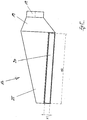
- FIG. 1 can be seen in a purely schematic representation of a dishwasher in the design of a program-controlled household dishwasher.
- the dishwasher 1 has, in a manner known per se, a housing 2 which terminates on the upper side by means of a cover plate 3.
- the housing 2 accommodates a washing container 5, which in turn provides a washing compartment 6.
- the washing compartment 6 serves to receive items to be cleaned.
- the washing compartment 6 For loading the washing compartment 6 with items to be cleaned has the washing compartment 5 via a charging opening 7. This is by means of a Spülraumt 8 fluid-tight manner, the Spülraumt 8 is rotatably mounted about a horizontally extending pivot axis.
- the dishes to be cleaned are treated with rinsing liquor, for which purpose the dishwasher 1 has a spraying device not shown in detail in the figures.
- the dishwasher 1 further has a condensation dryer 26. In the intended use case, this ensures that outside air 10 is sucked in via the air inlet 14.
- the aspirated outside air 10 is initially passed outside the side wall 15 and then outside the ceiling wall 16 of the washing container 5 as the air flow 11.
- the air flow 11 passes after passing through the side wall 15 in a gap 4 below the cover plate 3, from where it is discharged as exhaust air 12 to the surrounding the dishwasher 1 atmosphere again.
- rinsing takes place at the end of a cleaning program.
- the rinsing liquor and thus also the rinse container 5 recorded items to be warmed up to, for example, 55 degrees Celsius.
- the surface tension of the wash liquor is reduced.
- the rinsing solution is pumped out.
- the heat generated by the items to be washed evaporates the still remaining film of water.
- the Spülraumluft consequently saturates gradually with water vapor. If the Spülraumluft is saturated, no more water from the dishes and baskets dry.
- the Spülakuerwand 15 of the washing container 5 is cooled in the manner already described above.
- the temperature of the Spülraumwand 15 drops as a result, which leads to a drop below the dew point of the moist Spülraum poverty.
- the water vapor in the saturated Spülraum poverty can condense on the Spülraumwand 15.
- the Spülraum poverty is no longer saturated and can thus absorb moisture again.
- the above-described air duct is provided by the condensation dryer 26 provided according to the invention, which is designed according to the invention without blower.
- the condensation dryer 26 has an air supply channel 17. This is preferably a plastic component which serves for air supply.
- the air supply channel 17 has on the input side via a connection 18, with which the air supply channel is connected to the air inlet 14 formed in the base region 13 of the dishwasher 1.
- the air supply channel 17 provides the air inlet side a diffuser-shaped extension 19 of the flow cross section ready. Because of this extension 19 it is ensured that inflowing outside air 10 is slowed down in its inflow velocity, so that pressure losses in the sucked-in outside air are largely prevented.
- a channel section 25 connects to the diffuser-shaped extension 19, the flow cross-section of which is tapered starting from the air inlet-side extension 19 in the longitudinal direction 24. With reference to the drawing plane FIG. 3 this channel section 25 carries on the upper side a slot-shaped opening 20 which extends in the longitudinal direction 24 and via which, in the event of operation, the aspirated outlet air 10 is delivered as air flow 11.
- At the air supply passage 17 fluidly connects a cooling channel 21.
- the cooling channel 21 extends on the outside via a side wall 15 and the top wall 16 of the Spül organizations 5.
- the cooling channel 21 is introduced as an embossing in a washing container 5 covering insulation 22 or the insulation 22 is shaped so that between washing 5 and insulation 22 of the cooling channel 21 is formed.
- the insulation 22 is closed by the housing 2 or the cover plate 3.
- the insulation 22 in particular has a shape or embossing, through which the further top-side profile of the cooling channel 21 is formed between the washing container 5 and the insulation 22.
- the cooling channel 21 opens on the output side into an outlet opening 23 which is arranged, in particular, on the front side between the cover plate 3 and the rinsing container 5, and via which the airflow 11 passed through the cooling channel 21 is discharged as exhaust air 12.
- the operation of the condensation dryer 26 is the following: About the air duct 17 outside air 10 is sucked and transferred into the cooling channel 21. This happens due to the structural design of the air duct 17 basically free of pressure loss. On the warm side wall 15 of the washing compartment 5, the air flow 11 is heated, which leads to a cooling of the side wall 15. The heated air flow 11 increases due to thermal reasons (chimney effect) in the cooling channel 21, whereby a negative pressure on the air inlet side, resulting in a steady sucking in of outside air 10. The heated and ascended in the cooling channel 21 air flow 11 is discharged as heated exhaust air 12 via the outlet opening 23.
- the air guide is designed such that a connection to the room air only takes place on the air inlet side of the air supply duct 17 and on the air discharge side of the cooling duct 21 via the outlet opening 23.
- the air heated by the waste heat from the washing compartment 4 rises and flows above the washing compartment 5 via the outlet opening 23. Due to the resulting negative pressure, cooler room air is sucked in, which heats up again, creating a chimney effect.
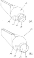
- FIGS. 8 and 9 show an alternative and preferred embodiment of the air supply duct 17.
- a shutter 27 is provided on the air inlet side of the air supply duct 17.
- the closure flap is rotatably disposed within the nozzle 18.
- An adjustment of the closure flap 27 takes place via an actuating drive 28 formed on the outside of the air feed channel 17.
- the actuating drive 28 preferably has an electric motor (not further illustrated in the figures) which is connected to the process control of the dishwasher 1. This allows program-dependent control of the closure flap 27 by the dishwasher-side control device.
- FIG. 8 shows the flap 27 in the open position. In this position, the flow cross-section of the air supply channel 17 is released. In contrast to this shows FIG. 9 the closure flap 27 in the closed position, in which position the flow cross-section of the air feed channel 17 is closed.
- the closure flap 17 can be carried out by means of the condensation dryer 26 a proper drying.
- the condensation dryer 26 is therefore akitiviert in the open position of the flap 27.
Abstract
Die Erfindung betrifft eine Geschirrspülmaschine, insbesondere programmgesteuerte Haushaltsgeschirrspülmaschine, mit einem einen Spülraum (4) bereitstellenden Spülbehälter (5) zur Aufnahme von zu reinigendem Spülgut und einem Kondensationstrockner (26) zur außenseitigen Beaufschlagung einer Seitenwand (15) des Spülbehälters (5) mit Außenluft (10), dadurch gekennzeichnet, dass der Kondensationstrockner (26) gebläsefrei ausgebildet ist und einen Luftzuführkanal (17) aufweist, der lufteingangsseitig eine diffusorförmig ausgebildete Erweiterung (19) des Strömungsquerschnitts bereitstellt.The invention relates to a dishwasher, in particular a program-controlled domestic dishwasher, having a washing compartment (5) for receiving items to be cleaned and a condensation dryer (26) for externally loading a side wall (15) of the washing compartment (5) with outside air (5). 10), characterized in that the condensation dryer (26) is formed fan-free and an air supply channel (17), the air inlet side provides a diffuser-shaped extension (19) of the flow cross-section.
Description
Die Erfindung betrifft eine Geschirrspülmaschine, insbesondere eine programmgesteuerte Haushaltsgeschirrspülmaschine, mit einem einen Spülraum bereitstellenden Spülbehälter zur Aufnahme von zu reinigendem Spülgut und einem Kondensationstrockner zur außenseitigen Beaufschlagung einer Seitenwand des Spülbehälters mit Außenluft.The invention relates to a dishwasher, in particular a program-controlled domestic dishwasher, with a washing compartment providing a washing compartment for receiving items to be cleaned and a condensation dryer for externally loading a side wall of the washing compartment with outside air.
Geschirrspülmaschinen im Allgemeinen sowie programmgesteuerte Haushaltsgeschirrspülmaschinen im Speziellen sind aus dem Stand der Technik an sich gut bekannt, weshalb es eines gesonderten druckschriftlichen Nachweises nicht bedarf. Es sei deshalb auch nur exemplarisch auf die
Geschirrspülmaschinen der in Rede stehenden Art verfügen über einen Spülbehälter, der einen Spülraum bereitstellt. Dieser Spülraum ist verwenderseitig über eine Beschickungsöffnung zugänglich, die mittels einer verschwenkbar gelagerten Spülraumtür fluiddicht verschließbar ist. Im bestimmungsgemäßen Verwendungsfall dient der Spülbehälter der Aufnahme von zu reinigendem Spülgut, bei dem es sich im Falle einer programmgesteuerten Haushaltsgeschirrspülmaschine beispielsweise um Geschirr, Besteckteile und/oder dergleichen handeln kann.Dishwashers of the type in question have a washing container, which provides a washing compartment. This washing compartment is accessible on the user side via a charging opening which can be closed in a fluid-tight manner by means of a pivotally mounted flushing door. In the intended use case, the washing container serves to receive items to be cleaned, which in the case of a program-controlled household dishwasher, for example, can be crockery, cutlery pieces and / or the like.
Zur Beaufschlagung von zu reinigendem Spülgut mit Spülflotte verfügt die Geschirrspülmaschine über eine spülraumseitig ausgebildete Sprüheinrichtung. Diese Sprüheinrichtung stellt in aller Regel verdrehbar gelagerte Sprüharme zur Verfügung, wobei typischerweise zwei oder drei solcher Sprüharme vorgesehen sind. Im bestimmungsgemäßen Verwendungsfall erfolgt eine Beaufschlagung des zu reinigenden Spülguts mit Spülflotte mittels sich drehender Sprüharme. Zwecks Versorgung der Sprüharme mit Spülflotte ist eine Umwälzpumpe vorgesehen, an die die Sprüharme strömungstechnisch angeschlossen sind.For loading of items to be cleaned with rinse liquor, the dishwasher has a scavenging chamber side formed spray. This spraying device generally provides rotatably mounted spray arms, with typically two or three such spray arms being provided. In the intended use case, a loading of the items to be cleaned with rinse liquor by means of rotating spray arms. For the purpose of supplying the spray arms with rinsing liquor, a circulating pump is provided, to which the spray arms are fluidically connected.
Zur Trocknung von Spülgut nach Abschluss einer bestimmungsgemäßen Reinigung verfügen aus dem Stand der Technik vorbekannte Geschirrspülmaschinen typischerweise über einen Kondensationstrockner. Dieser dient der außenseitigen Beaufschlagung einer Spülbehälterwand mit Außenluft, was zu einer Abkühlung der Spülbehälterwand mit der Folge führt, dass im Inneren des Spülbehälters befindliche feuchte Luft an der von außen abgekühlten Spülbehälterwand innenseitig auskondensieren kann. Der im Spülbehälter befindlichen feuchten Luft wird so Feuchtigkeit entzogen, was zur Trocknung des am Ende eines bestimmungsgemäß durchlaufenen Spülprogramms noch heißen Spülguts führt.For drying items to be washed after completion of a proper cleaning, dishwashers previously known from the prior art typically have a condensation dryer. This serves the outside admission of a Spülbehälterwand with outside air, resulting in a cooling of the Spülbehälterwand with the result that moist air located inside the Spülbehälters can condense on the inside cooled from the outside Spülbehälterwand. The moist air in the rinsing container is thus deprived of moisture, which leads to the drying of the dishes which are still hot at the end of an intended washing program.
Für eine außenseitige Beaufschlagung einer Spülbehälterwand verfügen aus dem Stand der Technik vorbekannte Kondensationstrockner über ein elektrisch betriebenes Gebläse. Sofern die Geschirrspülmaschine über eine Wärmepumpeneinrichtung verfügt, können der Kondensationstrockner und die Wärmepumpeneinrichtung ein gemeinsames Gebläse aufweisen, wie dies mit der
Geschirrspülmaschinen der vorbeschriebenen Art haben sich im alltäglichen Praxiseinsatz bewährt. Es besteht gleichwohl das beständige Bestreben, Verbesserungen vorzusehen, insbesondere mit Blick auf den Energieverbrauch. Es ist deshalb die Aufgabe der Erfindung, eine Geschirrspülmaschine der eingangs genannten Art dahingehend weiterzuentwickeln, dass im bestimmungsgemäßen Verwendungsfall ein verringerter Energieverbrauch ermöglicht ist. Ferner ist eine für den Verwender verbesserte Handhabung der Geschirrspülmaschine angestrebt.Dishwashers of the type described above have proven themselves in everyday practice. However, there is a constant drive to provide for improvements, especially with regard to energy consumption. It is therefore an object of the invention to further develop a dishwasher of the type mentioned in that a reduced energy consumption is possible in the intended use case. Furthermore, an improved handling of the dishwasher by the user is desired.
Zur Lösung dieser Aufgabe wird mit der Erfindung eine Geschirrspülmaschine der eingangs genannten Art vorgeschlagen, die sich dadurch auszeichnet, dass der Kondensationstrockner gebläsefrei ausgebildet ist und einen Luftzuführkanal aufweist, der lufteingangsseitig eine diffusorförmig ausgebildete Erweiterung des Strömungsquerschnitts bereitstellt.To achieve this object, a dishwasher of the aforementioned type is proposed with the invention is characterized in that the condensation dryer is formed fan-free and has an air supply duct, the air input side, providing a diffuser-shaped widening of the flow cross-section.
Der Kondensationstrockner der erfindungsgemäßen Geschirrspülmaschine ist gebläsefrei ausgebildet. Es wird mithin auf die Verwendung eines elektrisch betriebenen Gebläses vollends verzichtet. Dies hilft, im bestimmungsgemäßen Verwendungsfall Energie einzusparen, denn es wird für den Betrieb des erfindungsgemäßen Kondensationstrockners mangels Gebläse keine elektrische Energie benötigt.The condensation dryer of the dishwasher according to the invention is fan-free. It is therefore completely dispensed with the use of an electrically operated fan. This helps to save energy in the intended use case, because it requires no electrical energy for the operation of the condensation dryer according to the invention for lack of fan.
Zur gebläsefreien Beaufschlagung einer Spülraumwand mit Außenluft verfügt der Kondensationstrockner über einen Luftzuführkanal. Dieser Luftzuführkanal stellt lufteingangsseitig eine diffusorförmig ausgebildete Erweiterung des Strömungsquerschnitts bereit. Hierdurch wird die freie Konvektion der in den Luftführungskanal einströmenden Außenluft begünstigt, wodurch infolge des sogenannten Kamineffekts ein Luftstrom ohne die Notwendigkeit eines Gebläses entsteht.To blow-free a Spülraumwand with outside air, the condensation dryer has an air supply duct. This air supply channel provides On the input side, a diffuser-shaped extension of the flow cross-section ready. As a result, the free convection of the inflowing into the air duct outer air is promoted, creating an air flow due to the so-called chimney effect without the need for a blower.
Die erfindungsgemäß vorgesehene diffusorförmig ausgebildete Erweiterung des Strömungsquerschnitts sorgt im Betriebsfall dafür, dass es beim Ansaugen von Außenluft zu keinen oder nur geringen Druckverlusten kommt. Insoweit strömt durch freie Konvektion angesogene Außenluft außenseitig der Spülbehälterwand vorbei, was zu einem Abkühlen der Spülbehälterwand bei einem gleichzeitigen Erwärmen der daran vorbeiströmenden Luft führt. Die erwärmte Luft steigt weiter auf, infolgedessen es lufteingangsseitig zur Ausbildung eines Unterdrucks kommt. Außenluft wird hierdurch nachgesaugt, und zwar aufgrund der erfindungsgemäßen Ausgestaltung ohne nennenswerten Druckverlust. Die so angesogene Außenluft wird ebenfalls erwärmt, wobei dieser Zyklus aufrechterhalten bleibt, bis es zur Abkühlung der Spülbehälterwand auf Außenlufttemperatur gekommen ist.The inventively provided diffuser-shaped extension of the flow cross-section ensures in the case of operation that there is no or only slight pressure losses during the intake of outside air. In that regard, outside air drawn in by free convection flows outside the washing compartment wall, which leads to cooling of the washing compartment wall with simultaneous heating of the air flowing past it. The heated air continues to increase, as a result, it comes to the formation of a negative pressure on the air inlet side. Outside air is thereby sucked, due to the inventive design without significant pressure loss. The so-sucked outside air is also heated, this cycle is maintained until it has come to cool the Spülbehälterwand on outside air temperature.
Die mit der erfindungsgemäßen Ausgestaltung in vorteilhafter Weise erreichte Energieeinsparung im bestimmungsgemäßen Verwendungsfall ist dadurch bedingt, dass auf ein Gebläse zum Ansaugen von Außenluft verzichtet worden ist. Diese gebläsefreie Ausgestaltung ist aufgrund der Ausgestaltung des Luftzuführkanals möglich, da es die diffusorförmig ausgebildete Erweiterung des Strömungsquerschnitts gestattet, Außenluft ohne nennenswerten Druckverlust anzusaugen, sodass die an der Spülbehälterwand stattfindende Erwärmung der angesogenen Luft ausreichend ist, um kühlere Außenluft in hinreichendem Maße nachzufördern.The achieved with the inventive design in an advantageous manner energy savings in the intended use case is due to the fact that has been dispensed with a fan for sucking fresh air. This fan-free design is possible because of the design of the air supply channel, as it allows the diffuser-shaped extension of the flow cross-section to suck in outside air without significant pressure loss, so that taking place on the Spülbehälterwand heating of the absorbed air is sufficient to nachzufördern cooler outdoor air to a sufficient extent.
Von Vorteil der erfindungsgemäßen Ausgestaltung ist ferner, dass die Herstellkosten sowie die Montagekosten aufgrund des im Unterschied zum Stand der Technik entfallenen Gebläses verringert sind. Insoweit erbringt die erfindungsgemäße Ausgestaltung eine Kostenreduktion. Es ist darüber hinaus von Vorteil, dass im bestimmungsgemäßen Betrieb der Geschirrspülmaschine eine Geräuschreduktion erreicht ist, die dadurch bedingt ist, dass die durch ein Gebläse bedingten Strömungsgeräusche entfallen. Es kann so ein geräuscharmerer Betrieb der Geschirrspülmaschine bewerkstelligt werden, was eine für den Verwender verbesserte Handhabung bedingt. Nicht zuletzt wird durch den Wegfall des Gebläses auch die Störanfälligkeit der Geschirrspülmaschine reduziert, was ebenfalls zu einer verwenderseitigen Vereinfachung in der Handhabung beiträgt.Another advantage of the embodiment according to the invention is that the manufacturing costs and assembly costs are reduced due to the blower, which is not included in the prior art. In that regard, the embodiment of the invention provides a cost reduction. It is also advantageous that in the normal operation of the dishwasher, a noise reduction is achieved, which is due to the fact that eliminates the flow noise caused by a fan. It can be done so a quieter operation of the dishwasher, which requires improved handling for the user. Last but not least, the failure of the blower and the susceptibility of the Dishwasher reduced, which also contributes to a user-side simplification in handling.
Gemäß einem weiteren Merkmal der Erfindung zeichnet sich die Geschirrspülmaschine durch eine lufteingangsseitig des Luftzuführkanals ausgebildete Verschlussklappe aus. Die Verschlussklappe dient dazu, den Strömungsquerschnitt des Luftzuführkanals wahlweise zu verschließen oder zu öffnen. In der Verschlussstellung der Verschlussklappe ist der Luftzuführkanal lufteingangsseitig verschlossen, das heißt ein Eindringen von Außenluft in den Luftzuführkanal ist nicht möglich. Ein Eintritt von Außenluft in den Luftzuführkanal ist nur bei geöffneter Verschlussklappe gestattet, wenn sich also die Verschlussklappe in einer solchen Stellung befindet, dass der Strömungsquerschnitt des Luftzuführkanals zumindest teilweise freigegeben ist.According to a further feature of the invention, the dishwasher is characterized by a closure flap formed on the air inlet side of the air supply duct. The closure flap serves to selectively close or open the flow cross-section of the air supply channel. In the closed position of the closure flap, the air supply channel is closed on the air inlet side, that is to say an intrusion of outside air into the air supply channel is not possible. An entry of outside air into the air supply duct is only permitted when the shutter is open, that is to say when the shutter is in such a position that the flow cross-section of the air supply duct is at least partially released.
Die Ausgestaltung einer Verschlussklappe hat den Vorteil, den Kondensationstrockner wahlweise in Gebrauch zu nehmen, das heißt aktiv zu schalten. Dies gestattet es, einen Luftstrom entlang der Spülbehälterwand dann zu unterbinden, wenn eine Kühlung derselben nicht erwünscht ist, beispielsweise während eines stattfindenden Spülprozesses. Eine unerwünschte Abkühlung während eines stattfindenden Spülprozesses kann so mit dem Vorteil eines vermiedenen Energieverlustes verhindert werden. Eine Aktivierung, das heißt Ingangsetzung des Kondensationstrockners erfolgt erst mit Öffnen der Verschlussklappe zu einem Zeitpunkt, zu dem prozesstechnisch eine Trocknung durchzuführen ist, beispielsweise nach Durchlaufen eines Klarspülvorgangs. Es ist deshalb gemäß einem weiteren Merkmal der Erfindung bevorzugt, dass die Stellung der Verschlussklappe programmgesteuert einstellbar ist. Die Stellung der Verschlussklappe wird mithin in Abhängigkeit des von der Geschirrspülmaschine durchgeführten Spülprogramms eingestellt. Dabei ist während aller Spülphasen, in denen eine Trocknung nicht erwünscht ist, die Verschlussklappe in ihrer Verschlussstellung, so dass der Kondensationstrockner deaktiviert ist. Erst dann, wenn eine prozesstechnische Trocknung gewünscht ist, wird der Kondensationstrockner durch Überführen der Verschlussklappe aus der Verschlussstellung in die Offenstellung aktiviert.The design of a closure flap has the advantage of optionally taking the condensation dryer into use, that is to actively switch it. This makes it possible to prevent an air flow along the Spülbehälterwand then when cooling of the same is not desirable, for example, during a rinsing process taking place. An undesirable cooling during a rinsing process taking place can thus be prevented with the advantage of a avoided energy loss. An activation, that is to say start-up of the condensation dryer, takes place only when the closure flap is opened at a point in time at which drying is to be carried out in terms of process technology, for example after passing through a final-rinse operation. It is therefore preferred according to a further feature of the invention that the position of the flap is programmatically adjustable. The position of the flap is thus adjusted depending on the washing program carried out by the dishwasher. In this case, during all rinsing phases in which drying is not desired, the closure flap in its closed position, so that the condensation dryer is deactivated. Only then, when a process-technical drying is desired, the condensation dryer is activated by transferring the shutter from the closed position to the open position.
Es ist gemäß einem weiteren Merkmal der Erfindung vorgesehen, dass der Luftzuführkanal luftausgangsseitig eine sich in Längsrichtung des Luftzuführkanals erstreckende, schlitzförmige Öffnung aufweist. Im Betriebsfall wird also Außenluft eingangsseitig in den Luftzuführkanal eingesogen und ausgangsseitig über eine sich in Längsrichtung des Luftzuführkanals erstreckende Öffnung abgegeben. Diese Öffnung ist schlitzförmig ausgebildet, sodass in vorteilhafter Weise eine flächenhafte Beaufschlagung der zugehörigen Spülbehälterwand erfolgt, was eine optimierte Abkühlung der Spülbehälterwand bewirkt. Dabei ist die Erstreckung der schlitzförmigen Öffnung bevorzugter Weise derart optimiert ausgelegt, dass bei möglichst geringem Druckverlust der über den Luftzuführkanal zugeführten Außenluft eine möglichst breite Abdeckung der abzukühlenden Spülbehälterwand erfolgt.It is provided according to a further feature of the invention that the air supply duct on the air outlet side has a slot-shaped opening extending in the longitudinal direction of the air supply duct. In the operating case, so the outside air is sucked into the input side of the air supply duct and the output side via a in Delivered longitudinally extending opening of the air supply duct. This opening is slit-shaped, so that in an advantageous manner a two-dimensional loading of the associated Spülbehälterwand done, which causes an optimized cooling of the Spülbehälterwand. In this case, the extension of the slot-shaped opening is preferably optimized so that, with the lowest possible pressure loss of the outside air supplied via the air supply duct, the widest possible coverage of the rinsing vessel wall to be cooled takes place.
Gemäß einem weiteren Merkmal der Erfindung ist vorgesehen, dass sich der Strömungsquerschnitt des Luftführungskanals ausgehend von der lufteingangsseitigen Erweiterung in Längsrichtung verjüngt. Der Strömungsraum des Luftführungskanals weist mithin eingangsseitig eine diffusorförmige Erweiterung auf, gefolgt von einer Verjüngung in Längsrichtung. Die Ausbildung der Verjüngung erbringt den Vorteil, dass über die Längserstreckung der schlitzförmigen Ausgabeöffnung im Wesentlichen gleiche Druckverhältnisse anliegen, sodass eine gleichmäßige Beaufschlagung der ausgangsseitigen Öffnung und damit der zugehörigen Spülbehälterwand mit Außenluft erfolgt.According to a further feature of the invention, it is provided that the flow cross-section of the air duct tapers in the longitudinal direction, starting from the air inlet-side extension. The flow space of the air duct thus has on the input side a diffuser-shaped extension, followed by a taper in the longitudinal direction. The formation of the taper affords the advantage that over the longitudinal extent of the slot-shaped dispensing opening substantially equal pressure conditions are applied, so that a uniform loading of the outlet-side opening and thus the associated Spülbehälterwand done with outside air.
Gemäß einem weiteren Merkmal der Erfindung ist vorgesehen, dass der Kondensationstrockner einen luftausgangsseitig an den Luftführungskanal strömungstechnisch angeschlossenen Kühlkanal aufweist. Der Kühlkanal erstreckt sich entlang einer Seitenwand des Spülbehälters sowie der Deckenwand des Spülbehälters. Im bestimmungsgemäßen Verwendungsfall wird mithin Außenluft angesaugt, die über den Luftzuführungskanal einströmt und aufgrund der konstruktiven Ausgestaltung des Luftzuführungskanals ohne wesentlichen Druckverlust zum Kühlkanal gefördert wird. Infolge einer Durchströmung des Kühlkanals wird die Seitenwand des Spülbehälters gekühlt. In schon vorbeschriebener Weise wird dabei der Kamineffekt genutzt, infolgedessen erwärmte Außenluft im Kühlkanal aufsteigt, ausgangsseitig abströmt und infolgedessen im Luftzuführungskanal ein Unterdruck entsteht, sodass weitere Außenluft nachgesogen wird.According to a further feature of the invention, it is provided that the condensation dryer has a cooling channel which is fluidly connected to the air duct on the air outlet side. The cooling channel extends along a side wall of the washing container and the top wall of the washing container. In the intended use case, therefore, outside air is sucked in, which flows in via the air supply duct and due to the structural design of the air supply duct is conveyed to the cooling duct without significant pressure loss. As a result of a flow through the cooling channel, the side wall of the washing container is cooled. In the manner described above, the chimney effect is used, as a result, heated outside air rises in the cooling channel, flows out on the output side and as a result, a negative pressure is created in the air supply channel, so that more outside air is added.
Der Kühlkanal mündet gemäß einem weiteren Merkmal der Erfindung maschinenvorderseitig in eine Austrittsöffnung. Über diese Austrittsöffnung wird im bestimmungsgemäßen Verwendungsfall die durch den Kühlkanal hindurchgeführte Außenluft abgegeben. Sie gelangt von dort aus in die die Geschirrspülmaschine umgebende Atmosphäre.The cooling channel opens according to a further feature of the invention, machine front side in an outlet opening. In the intended use case, the outside air passed through the cooling channel is discharged via this outlet opening. From there it enters the dishwasher surrounding atmosphere.
Es ist gemäß einem weiteren Merkmal der Erfindung vorgesehen, dass der Kühlkanal einen in Strömungsrichtung gleichbleibend groß ausgebildeten Strömungsquerschnitt bereitstellt. Durch diese Ausgestaltung wird in vorteilhafter Weise sichergestellt, dass es zu keinen nennenswerten Druckverlusten in der durch den Kühlkanal hindurchgeführten Außenluft kommt.It is provided according to a further feature of the invention that the cooling channel provides a flow cross-section of constant size in the flow direction. This configuration ensures in an advantageous manner that no significant pressure losses occur in the outside air which is passed through the cooling channel.
Gemäß einem weiteren Merkmal der Erfindung ist vorgesehen, dass der Kühlkanal im Wesentlichen luftdicht an den Luftzuführungskanal angeschlossen ist. Durch diese Maßnahme wird in vorteilhafter Weise sichergestellt, dass es zu keiner Durchmischung der aus dem Luftzuführungskanal in den Kühlkanal überströmenden Außenluft mit Umgebungsluft kommt. Eine gleichförmige und dem Grunde nach druckverlustfreie Überführung der angesogenen Außenluft aus dem Luftzuführungskanal in den Kühlkanal wird so begünstigt.According to a further feature of the invention it is provided that the cooling channel is connected substantially airtight to the air supply passage. By this measure, it is ensured in an advantageous manner that there is no mixing of the outside air flowing from the air supply channel into the cooling channel with ambient air. A uniform and basically pressure loss-free transfer of the suctioned outside air from the air supply passage in the cooling channel is so favored.
Gemäß einem weiteren Merkmal der Erfindung ist vorgesehen, dass der Kühlkanal im Wesentlichen fluiddicht zur Umgebungsatmosphäre ausgebildet ist. Gemäß diesem Merkmal findet nicht nur eine im Wesentlichen fluiddichte Anbindung des Luftzuführungskanals an den Kühlkanal, sondern auch eine im Wesentlichen fluiddichte Ausgestaltung des Kühlkanals statt. Auch durch diese Maßnahme wird eine gleichförmige und dem Grunde nach druckverlustfreie Durchströmung des Kühlkanals mit Außenluft begünstigt.According to a further feature of the invention it is provided that the cooling channel is formed substantially fluid-tight to the ambient atmosphere. According to this feature, not only a substantially fluid-tight connection of the air supply channel to the cooling channel, but also a substantially fluid-tight configuration of the cooling channel takes place. Also by this measure a uniform and basically pressure-loss-free flow through the cooling channel is favored with outside air.
Gemäß einem weiteren Merkmal der Erfindung ist vorgesehen, dass der Kühlkanal als eine in eine Dämmung des Spülbehälters eingebrachte Prägung ausgebildet ist. Der Spülbehälter ist typischerweise aus Wärmeschutzgründen isoliert ausgebildet. Typischerweise kommt zu diesem Zweck eine Dämmung zum Einsatz, die außenseitig am Spülbehälter angebracht ist. Zur Ausbildung des erfindungsgemäß vorgesehenen Kühlkanals wird diese ohnehin vorgesehene Dämmung des Spülbehälters mit einer Prägung ausgerüstet, wodurch der erfindungsgemäße Kühlkanal entsteht. Diese Ausgestaltung ist in der Herstellung besonders einfach und darüber hinaus von Kostenvorteil. Zudem erbringt das Dämmmaterial eine hinreichende fluiddichte Ausgestaltung des Kühlkanals. Oberseitig ist der Kühlkanal durch das Außengehäuse beziehungsweise eine Abdeckplatte der Geschirrspülmaschine begrenzt.According to a further feature of the invention it is provided that the cooling channel is formed as an introduced into an insulation of the washing container embossing. The rinsing container is typically formed insulated for thermal protection reasons. Typically, an insulation is used for this purpose, which is attached to the outside of the washing. To form the cooling channel provided according to the invention, this already provided insulation of the washing container is equipped with an embossment, whereby the cooling channel according to the invention is formed. This embodiment is particularly easy to manufacture and moreover of cost advantage. In addition, the insulating material provides a sufficient fluid-tight design of the cooling channel. On the upper side, the cooling channel is limited by the outer housing or a cover plate of the dishwasher.
Mit der erfindungsgemäßen Ausgestaltung wird insgesamt ein Kondensationstrockner vorgeschlagen, der aufgrund der vorbeschriebenen konstruktiven Merkmale eine gebläsefreie Ausgestaltung ermöglicht, sodass im bestimmungsgemäßen Verwendungsfall ein verringerter Energieverbrauch in vorteilhafter Weise die Folge ist.With the embodiment according to the invention a condensation dryer is proposed as a whole, which allows a fan-free design due to the above-described constructive features, so that in the intended use, a reduced energy consumption in an advantageous manner the result.
Weitere Merkmale und Vorteile der Erfindung ergeben sich aus der nachfolgenden Beschreibung anhand der Figuren. Dabei zeigen:
- Figur 1
- in schematischer Seitendarstellung eine erfindungsgemäße Geschirrspülmaschine;
Figur 2- in schematischer Perspektivansicht eine erfindungsgemäße Geschirrspülmaschine;
- Figur 3
- in schematischer Perspektivansicht einen nach der Erfindung vorgeschlagenen Kondensationstrockner im Detail;
Figur 4- in schematischer Perspektivansicht einen Luftzuführungskanal nach der Erfindung;
Figur 5- in schematischer Draufsicht den
Luftzuführungskanal nach Figur 4 ; Figur 6- in schematischer Seitenansicht den
Luftzuführungskanal nach Figur 4 ; - Figur 7
- in schematischer Rückansicht den
Luftzuführungskanal nach Figur 4 ; Figur 8- in schematischer Perspektivansicht einen Luftzuführkanal gemäß einer zweiten Ausführungsform mit einer Verschlussklappe in Offenstellung und
Figur 9- in schematischer Perspektivansicht einen Luftzuführkanal gemäß einer zweiten Ausführungsform mit einer Verschlussklappe in Verschlussstellung.
- FIG. 1
- a schematic side view of a dishwasher according to the invention;
- FIG. 2
- a schematic perspective view of a dishwasher according to the invention;
- FIG. 3
- in a schematic perspective view of a proposed invention condensation dryer in detail;
- FIG. 4
- in a schematic perspective view of an air supply duct according to the invention;
- FIG. 5
- in a schematic plan view the air supply duct after
FIG. 4 ; - FIG. 6
- in a schematic side view of the air supply duct
FIG. 4 ; - FIG. 7
- in a schematic rear view of the air supply duct
FIG. 4 ; - FIG. 8
- in a schematic perspective view of an air supply duct according to a second embodiment with a shutter in the open position and
- FIG. 9
- in a schematic perspective view of an air supply duct according to a second embodiment with a shutter in the closed position.
Die Geschirrspülmaschine 1 verfügt in an sich bekannter Weise über ein Gehäuse 2, das oberseitig mittels einer Abdeckplatte 3 abschließt. Das Gehäuse 2 nimmt einen Spülbehälter 5 auf, der seinerseits einen Spülraum 6 bereitstellt. Der Spülraum 6 dient der Aufnahme von zu reinigendem Spülgut.The dishwasher 1 has, in a manner known per se, a
Zur Beschickung des Spülraums 6 mit zu reinigendem Spülgut verfügt der Spülbehälter 5 über eine Beschickungsöffnung 7. Diese ist mittels einer Spülraumtür 8 fluiddicht verschließbar, wobei die Spülraumtür 8 um eine horizontal verlaufende Schwenkachse drehverschwenkbar gelagert ist.For loading the
Im bestimmungsgemäßen Verwendungsfall erfolgt eine Beaufschlagung des zu reinigenden Spülguts mit Spülflotte, zu welchem Zweck die Geschirrspülmaschine 1 über eine in den Figuren nicht näher dargestellte Sprüheinrichtung verfügt.When used as intended, the dishes to be cleaned are treated with rinsing liquor, for which purpose the dishwasher 1 has a spraying device not shown in detail in the figures.
Wie sich insbesondere aus einer Zusammenschau der
Die Geschirrspülmaschine 1 verfügt des Weiteren über einen Kondensationstrockner 26. Dieser sorgt im bestimmungsgemäßen Verwendungsfall dafür, dass über den Lufteinlass 14 Außenluft 10 angesaugt wird. Die angesogene Außenluft 10 wird als Luftstrom 11 zunächst außenseitig der Seitenwand 15 und alsdann außenseitig der Deckenwand 16 des Spülbehälters 5 vorbeigeführt. Dabei gelangt der Luftstrom 11 nach einem Passieren der Seitenwand 15 in einen Spaltraum 4 unterhalb der Abdeckplatte 3, von wo aus er als Abluft 12 an die die Geschirrspülmaschine 1 umgebende Atmosphäre wieder abgegeben wird.The dishwasher 1 further has a
Im bestimmungsgemäßen Einsatzfall erfolgt zum Abschluss eines Reinigungsprogramms ein Klarspülen. Die Spülflotte und damit auch das vom Spülbehälter 5 aufgenommene Spülgut werden dabei auf beispielsweise 55 Grad Celsius aufgewärmt. Durch Zugabe eines Klarspülmittels wird die Oberflächenspannung der Spülflotte herabgesetzt. Zum Ende des Klarspülens wird die Spülflotte abgepumpt. In einer Abtropfphase kann Restfeuchtigkeit vom Spülgut und den im Spülbehälter befindlichen Körben zur Aufnahme von Spülgut abtropfen beziehungsweise ablaufen, was durch die niedrige Oberflächenspannung begünstigt wird. Die Eigenwärme des Spülguts lässt den noch zurückbleibenden Wasserfilm verdunsten. Die Spülraumluft sättigt sich folglich allmählich mit Wasserdampf an. Ist die Spülraumluft gesättigt, kann kein weiteres Wasser vom Spülgut und den Körben abtrocknen. Um die Feuchtigkeit in der Spülraumluft zu senken und somit wieder aufnahmefähig zu machen, wird die Spülbehälterwand 15 des Spülbehälters 5 in der schon vorbeschriebenen Weise gekühlt. Die Temperatur der Spülraumwand 15 sinkt infolgedessen ab, was zu einer Unterschreitung des Taupunkts der feuchten Spülraumluft führt. Der Wasserdampf in der gesättigten Spülraumluft kann an der Spülraumwand 15 kondensieren. Die Spülraumluft ist nicht mehr gesättigt und kann somit wieder Feuchtigkeit aufnehmen.When used as intended, rinsing takes place at the end of a cleaning program. The rinsing liquor and thus also the rinse
Die vorbeschriebene Luftführung wird durch den erfindungsgemäß vorgesehenen Kondensationstrockner 26 besorgt, der erfindungsgemäß gebläsefrei ausgestaltet ist.The above-described air duct is provided by the
Der konstruktive Aufbau des Kondensationstrockners 26 ergibt sich insbesondere aus der Darstellung nach
Der Luftzuführungskanal 17 verfügt eingangsseitig über einen Stutzen 18, mit welchem der Luftzuführungskanal an den in dem Sockelbereich 13 der Geschirrspülmaschine 1 ausgebildeten Lufteinlass 14 angeschlossen ist. Der Luftzuführungskanal 17 stellt lufteingangsseitig eine diffusorförmig ausgebildete Erweiterung 19 des Strömungsquerschnitts bereit. Aufgrund dieser Erweiterung 19 ist sichergestellt, dass einströmende Außenluft 10 in ihrer Einströmgeschwindigkeit verlangsamt wird, sodass Druckverluste in der eingesogenen Außenluft weitestgehend verhindert sind. In Durchströmungsrichtung schließt sich an die diffusorförmig ausgebildete Erweiterung 19 ein Kanalabschnitt 25 an, dessen Strömungsquerschnitt ausgehend von der lufteingangsseitigen Erweiterung 19 in Längsrichtung 24 verjüngt ausgebildet ist. Mit Bezug auf die Zeichnungsebene nach
An den Luftzuführungskanal 17 schließt sich strömungstechnisch ein Kühlkanal 21 an.At the
Dieser ist lufteingangsseitig an die Öffnung 20 des Luftzuführungskanals 17 angeschlossen, sodass im Betriebsfall über den Luftzuführungskanal 17 angesogene Außenluft 10 als Luftstrom 11 in den Kühlkanal 21 übergeben wird.This is the air inlet connected to the
Wie insbesondere die Darstellung nach
Der Kühlkanal 21 mündet ausgangsseitig in eine Austrittsöffnung 23, die insbesondere vorderseitig zwischen Abdeckplatte 3 und Spülbehälter 5 angeordnet ist, und über die der den Kühlkanal 21 passierte Luftstrom 11 als Abluft 12 abgegeben wird.The cooling
Die Funktionsweise des Kondensationstrockners 26 ist die Folgende: Über den Luftführungskanal 17 wird Außenluft 10 angesogen und in den Kühlkanal 21 überführt. Dies geschieht aufgrund der konstruktiven Ausgestaltung des Luftführungskanals 17 dem Grunde nach druckverlustfrei. An der warmen Seitenwand 15 des Spülbehälters 5 erwärmt sich der Luftstrom 11, was zu einer Abkühlung der Seitenwand 15 führt. Der erwärmte Luftstrom 11 steigt thermisch bedingt (Kamineffekt) im Kühlkanal 21 auf, wodurch lufteingangsseitig ein Unterdruck entsteht, was zu einem stetigen Nachsaugen von Außenluft 10 führt. Der erwärmte und im Kühlkanal 21 aufgestiegene Luftstrom 11 wird als erwärmte Abluft 12 über die Austrittsöffnung 23 abgegeben.The operation of the
Der Luftzuführungskanal 17 ist im Detail in den
- Die Breite der Öffnung 20 (Maß x1) ist so gestaltet, dass der gesamte Spaltraum zwischen der Seitenwand 15 des
Spülbehälters 5 und der zugehörigen Außenwand des Gehäuses 2 ausgefüllt ist. Ungewünschte Verwirbelungen mit der die Geschirrspülmaschine umgebenden Raumluft sind so vermieden. Die Breite der Öffnung 20 sollteim Übrigen 10 Millimeter nicht unterschreiten. - Die Länge der Öffnung 20 (Maß x2) ist bevorzugter Weise so gestaltet, dass möglichst die gesamte Tiefe der Seitenwand 15 des
Spülbehälters 5 abgedeckt ist. Sollte dies aufgrund von Bauraumbegrenzungen nicht möglich sein, ist dieLänge der Öffnung 20 so groß wie möglich zu wählen, sie sollte in jedem Fall aber mindestens 50 Prozent der Tiefe der Geschirrspülmaschine 1 entsprechen. - Der Radius des Kanalabschnitts 25 am hinteren Ende (Maß r1) ist so gewählt, dass er der Breite der Öffnung 20 (Maß x1) entspricht. Je nach Einbaubedingungen kann dies gegebenenfalls auch variieren, wobei der Radius r1
im Bereich von 0,5 *x1 bis 4 * x1 liegen sollte. Die zugehörige Querschnittsfläche liegt deshalb in diesem Bereich zwischen 0,5 *π* x12 ≤ Querschnittsfläche ≤ 4 * π * x12. Der Kanalabschnitt 25 erweitert sich ausgehend von der hinteren Querschnittsfläche bis zum strömungstechnischenAnfang der Öffnung 20 auf sein Maximum. Der Radius an dieser Stelle beträgt r2 und ist bevorzugter Weise so gewählt, dass er 2,5 * x1 entspricht. Hierdurch ergibt sich für den Winkel w2 ein Winkelmaß von circa 15 Grad. Dieser Öffnungswinkel sollte je nach Einbaubedingungen im Bereich zwischen 10 Grad und 20 Grad liegen.- Der Öffnungswinkel w1 sollte ein Winkelmaß von 30 Grad nicht unterschreiten.
- The width of the opening 20 (dimension x1) is designed so that the entire gap space between the
side wall 15 of thewashing compartment 5 and the associated outer wall of thehousing 2 is filled. Unwanted turbulence with the ambient air surrounding the dishwasher are thus avoided. Incidentally, the width of theopening 20 should not be less than 10 millimeters. - The length of the opening 20 (dimension x2) is preferably designed so that as far as possible the entire depth of the
side wall 15 of thewashing compartment 5 is covered. If this is not possible due to space limitations, the length of theopening 20 should be as large as possible to choose, but it should in any case at least 50 percent of the depth of the dishwasher 1 correspond. - The radius of the
channel portion 25 at the rear end (dimension r1) is chosen so that it corresponds to the width of the opening 20 (dimension x1). Depending on the installation conditions, this may also vary, where the radius r1 should be in the range of 0.5 * x1 to 4 * x1. Therefore, the associated cross-sectional area is in this range between 0.5 * π * x1 ≤ 2 cross-sectional area ≤ 4 * π * x1. 2 - The
channel portion 25 extends from the rear cross-sectional area to the fluidic beginning of theopening 20 to its maximum. The radius at this point is r2 and is preferably chosen to be 2.5 * x1. This results in an angle of approximately 15 degrees for the angle w2. Depending on the installation conditions, this opening angle should be between 10 degrees and 20 degrees. - The opening angle w1 should not fall below an angle of 30 degrees.
Neben der Luftführung durch den Luftzuführkanal 17 hindurch ist von Bedeutung, dass die angesogene Außenluft ausschließlich die Spülraumwand 15 kühlt und nicht andere Bauteile der Geschirrspülmaschine 1. Zudem ist eine Vermischung der von der Spülraumwand 15 aufgewärmten Luft mit der die Geschirrspülmaschine 1 umgebenden Raumluft zu vermeiden, die sich insbesondere zwischen Spülraum 5 und Gehäuse 2 befindet. Um dies zu erreichen, wird der durch Prägung in die Dämmung 22 eingebrachte Kühlkanal 21 so ausgebildet, dass eine Trennung des Kühlkanals 21 zum Spaltraum zwischen Spülbehälter 5 und Gehäuse 2 sichergestellt ist. Es können in diesem Zusammenhang auch zusätzliche Dämmdichtstreifen vorgesehen sein, die für einen im Wesentlichen fluiddichten Anschluss des Luftführungskanals 14 an den Kühlkanal 21 Sorge tragen.In addition to the air flow through the
Die Luftführung ist insgesamt so gestaltet, dass eine Verbindung zur Raumluft nur lufteingangsseitig des Luftzuführungskanals 17 sowie luftabgabeseitig des Kühlkanals 21 über die Austrittsöffnung 23 stattfindet. Hierdurch steigt die durch die Abwärme vom Spülraum 4 erwärmte Luft auf und strömt oberhalb des Spülbehälters 5 über die Austrittsöffnung 23 ab. Aufgrund des hierdurch entstehenden Unterdrucks wird kühlere Raumluft nachgesaugt, die sich erneut erwärmt, wodurch ein Kamineffekt entsteht.Overall, the air guide is designed such that a connection to the room air only takes place on the air inlet side of the
Die
Sofern sich die Verschlussklappe in Offenstellung gemäß
Sobald die Verschlussklappe 27 aus ihrer Offenstellung nach
- 1 Geschirrspülmaschine1 dishwasher
- 2 Gehäuse2 housings
- 3 Abdeckplatte3 cover plate
- 4 Spaltraum4 gap space
- 5 Spülbehälter5 rinse tanks
- 6 Spülraum6 washing room
- 7 Beschickungsöffnung7 feed opening
- 8 Spülraumtür8 washroom door
- 9 Blende9 aperture
- 10 Außenluft10 outside air
- 11 Luftstrom11 airflow
- 12 Abluft12 exhaust air
- 13 Sockelbereich13 base area
- 14 Lufteinlass14 air intake
- 15 Seitenwand15 side wall
- 16 Deckenwand16 ceiling wall
- 17 Luftführungskanal17 air duct
- 18 Stutzen18 nozzles
- 19 Erweiterung19 extension
- 20 Öffnung20 opening
- 21 Kühlkanal21 cooling channel
- 22 Dämmung22 insulation
- 23 Austrittsöffnung23 outlet opening
- 24 Längsrichtung24 longitudinal direction
- 25 Kanalabschnitt25 channel section
- 26 Kondensationstrockner26 condensation dryers
- 27 Verschlussklappe27 closing flap
- 28 Stelltrieb28 actuator
Claims (13)
Applications Claiming Priority (1)
| Application Number | Priority Date | Filing Date | Title |
|---|---|---|---|
| DE102016103921.7A DE102016103921A1 (en) | 2016-03-04 | 2016-03-04 | dishwasher |
Publications (2)
| Publication Number | Publication Date |
|---|---|
| EP3213666A1 true EP3213666A1 (en) | 2017-09-06 |
| EP3213666B1 EP3213666B1 (en) | 2019-11-13 |
Family
ID=58046550
Family Applications (1)
| Application Number | Title | Priority Date | Filing Date |
|---|---|---|---|
| EP17156182.2A Active EP3213666B1 (en) | 2016-03-04 | 2017-02-15 | Dishwasher |
Country Status (2)
| Country | Link |
|---|---|
| EP (1) | EP3213666B1 (en) |
| DE (1) | DE102016103921A1 (en) |
Cited By (1)
| Publication number | Priority date | Publication date | Assignee | Title |
|---|---|---|---|---|
| US10863882B2 (en) | 2018-08-13 | 2020-12-15 | Electrolux Home Products, Inc. | Appliance drying duct |
Families Citing this family (1)
| Publication number | Priority date | Publication date | Assignee | Title |
|---|---|---|---|---|
| US20230046683A1 (en) * | 2021-08-11 | 2023-02-16 | Whirlpool Corporation | Air barrier for door condensation |
Citations (6)
| Publication number | Priority date | Publication date | Assignee | Title |
|---|---|---|---|---|
| US3050866A (en) * | 1960-06-13 | 1962-08-28 | Gen Electric | Dishwasher with drying means |
| DE3515592A1 (en) * | 1985-04-30 | 1986-11-06 | Bosch-Siemens Hausgeräte GmbH, 8000 München | Dishwasher with condensation surface for precipitating the steam occurring in the washing compartment |
| EP1825800A2 (en) * | 2006-02-22 | 2007-08-29 | V-Zug AG | Dishwasher having a means for removing moisture from the tub |
| DE102010002086A1 (en) * | 2010-02-18 | 2011-08-18 | BSH Bosch und Siemens Hausgeräte GmbH, 81739 | Dryer with adsorber unit and method for its operation |
| DE102013101861A1 (en) | 2013-02-26 | 2014-08-28 | Miele & Cie. Kg | Dishwasher, in particular household dishwasher |
| WO2014174784A1 (en) * | 2013-04-23 | 2014-10-30 | パナソニックIpマネジメント株式会社 | Dish washer/dryer |
Family Cites Families (1)
| Publication number | Priority date | Publication date | Assignee | Title |
|---|---|---|---|---|
| DE102012223776A1 (en) * | 2012-12-19 | 2014-06-26 | BSH Bosch und Siemens Hausgeräte GmbH | Sorption device for a household appliance and corresponding household appliance |
-
2016
- 2016-03-04 DE DE102016103921.7A patent/DE102016103921A1/en not_active Ceased
-
2017
- 2017-02-15 EP EP17156182.2A patent/EP3213666B1/en active Active
Patent Citations (6)
| Publication number | Priority date | Publication date | Assignee | Title |
|---|---|---|---|---|
| US3050866A (en) * | 1960-06-13 | 1962-08-28 | Gen Electric | Dishwasher with drying means |
| DE3515592A1 (en) * | 1985-04-30 | 1986-11-06 | Bosch-Siemens Hausgeräte GmbH, 8000 München | Dishwasher with condensation surface for precipitating the steam occurring in the washing compartment |
| EP1825800A2 (en) * | 2006-02-22 | 2007-08-29 | V-Zug AG | Dishwasher having a means for removing moisture from the tub |
| DE102010002086A1 (en) * | 2010-02-18 | 2011-08-18 | BSH Bosch und Siemens Hausgeräte GmbH, 81739 | Dryer with adsorber unit and method for its operation |
| DE102013101861A1 (en) | 2013-02-26 | 2014-08-28 | Miele & Cie. Kg | Dishwasher, in particular household dishwasher |
| WO2014174784A1 (en) * | 2013-04-23 | 2014-10-30 | パナソニックIpマネジメント株式会社 | Dish washer/dryer |
Cited By (1)
| Publication number | Priority date | Publication date | Assignee | Title |
|---|---|---|---|---|
| US10863882B2 (en) | 2018-08-13 | 2020-12-15 | Electrolux Home Products, Inc. | Appliance drying duct |
Also Published As
| Publication number | Publication date |
|---|---|
| EP3213666B1 (en) | 2019-11-13 |
| DE102016103921A1 (en) | 2017-09-07 |
Similar Documents
| Publication | Publication Date | Title |
|---|---|---|
| DE3842997C2 (en) | dishwasher | |
| EP2120671B1 (en) | Method for implementing a drying program section in washing equipment with a condensation drying device | |
| EP1827198B2 (en) | Dishwashing machine | |
| DE102007019298B4 (en) | dishwasher | |
| EP2777471B1 (en) | Dishwasher, in particular household dishwasher | |
| EP1835841B1 (en) | Dishwasher | |
| EP1833354B1 (en) | Dishwasher | |
| DE102006012217B4 (en) | Dishwasher with counter-convection airflow | |
| EP3214990B1 (en) | Dishwasher comprising a drying unit | |
| EP1284627A2 (en) | Device for the drying of crockery in a dishwasher | |
| DE102005023428A1 (en) | Commercial dishwasher | |
| EP2371258A2 (en) | Dishwasher with door gap ventilation | |
| WO2005070274A1 (en) | Control system dependent on operating phases, for a device for recovering heat from continuous dishwashers | |
| EP3213666B1 (en) | Dishwasher | |
| EP3384822B1 (en) | Dishwasher, specifically domestic dishwasher | |
| DE3515592C2 (en) | ||
| EP3718460B1 (en) | Dishwasher, in particular a domestic dishwashing machine | |
| DE102019108965A1 (en) | Dishwasher, in particular household dishwasher | |
| DE7800591U1 (en) | DISHWASHING MACHINE FOR COMMERCIAL USE | |
| DE4029958C2 (en) | Dishwasher with a vent | |
| DE102021103231B4 (en) | Commercial dishwashing machine and method of operating such | |
| EP1701649B1 (en) | Dishwasher with drying device | |
| EP2636357A1 (en) | Dishwasher, in particular household dishwasher | |
| EP3170438A1 (en) | Dishwasher with a heat pump | |
| DE2253624C3 (en) | Device for extracting, cooling and drying steam from a dishwasher |
Legal Events
| Date | Code | Title | Description |
|---|---|---|---|
| PUAI | Public reference made under article 153(3) epc to a published international application that has entered the european phase |
Free format text: ORIGINAL CODE: 0009012 |
|
| STAA | Information on the status of an ep patent application or granted ep patent |
Free format text: STATUS: THE APPLICATION HAS BEEN PUBLISHED |
|
| AK | Designated contracting states |
Kind code of ref document: A1 Designated state(s): AL AT BE BG CH CY CZ DE DK EE ES FI FR GB GR HR HU IE IS IT LI LT LU LV MC MK MT NL NO PL PT RO RS SE SI SK SM TR |
|
| AX | Request for extension of the european patent |
Extension state: BA ME |
|
| STAA | Information on the status of an ep patent application or granted ep patent |
Free format text: STATUS: REQUEST FOR EXAMINATION WAS MADE |
|
| 17P | Request for examination filed |
Effective date: 20180118 |
|
| RBV | Designated contracting states (corrected) |
Designated state(s): AL AT BE BG CH CY CZ DE DK EE ES FI FR GB GR HR HU IE IS IT LI LT LU LV MC MK MT NL NO PL PT RO RS SE SI SK SM TR |
|
| GRAP | Despatch of communication of intention to grant a patent |
Free format text: ORIGINAL CODE: EPIDOSNIGR1 |
|
| STAA | Information on the status of an ep patent application or granted ep patent |
Free format text: STATUS: GRANT OF PATENT IS INTENDED |
|
| INTG | Intention to grant announced |
Effective date: 20190709 |
|
| GRAS | Grant fee paid |
Free format text: ORIGINAL CODE: EPIDOSNIGR3 |
|
| GRAA | (expected) grant |
Free format text: ORIGINAL CODE: 0009210 |
|
| STAA | Information on the status of an ep patent application or granted ep patent |
Free format text: STATUS: THE PATENT HAS BEEN GRANTED |
|
| AK | Designated contracting states |
Kind code of ref document: B1 Designated state(s): AL AT BE BG CH CY CZ DE DK EE ES FI FR GB GR HR HU IE IS IT LI LT LU LV MC MK MT NL NO PL PT RO RS SE SI SK SM TR |
|
| REG | Reference to a national code |
Ref country code: CH Ref legal event code: EP Ref country code: AT Ref legal event code: REF Ref document number: 1200818 Country of ref document: AT Kind code of ref document: T Effective date: 20191115 |
|
| REG | Reference to a national code |
Ref country code: DE Ref legal event code: R084 Ref document number: 502017002823 Country of ref document: DE |
|
| REG | Reference to a national code |
Ref country code: DE Ref legal event code: R096 Ref document number: 502017002823 Country of ref document: DE |
|
| REG | Reference to a national code |
Ref country code: IE Ref legal event code: FG4D Free format text: LANGUAGE OF EP DOCUMENT: GERMAN |
|
| REG | Reference to a national code |
Ref country code: GB Ref legal event code: 746 Effective date: 20191121 |
|
| REG | Reference to a national code |
Ref country code: NL Ref legal event code: MP Effective date: 20191113 |
|
| REG | Reference to a national code |
Ref country code: LT Ref legal event code: MG4D |
|
| PG25 | Lapsed in a contracting state [announced via postgrant information from national office to epo] |
Ref country code: BG Free format text: LAPSE BECAUSE OF FAILURE TO SUBMIT A TRANSLATION OF THE DESCRIPTION OR TO PAY THE FEE WITHIN THE PRESCRIBED TIME-LIMIT Effective date: 20200213 Ref country code: FI Free format text: LAPSE BECAUSE OF FAILURE TO SUBMIT A TRANSLATION OF THE DESCRIPTION OR TO PAY THE FEE WITHIN THE PRESCRIBED TIME-LIMIT Effective date: 20191113 Ref country code: PT Free format text: LAPSE BECAUSE OF FAILURE TO SUBMIT A TRANSLATION OF THE DESCRIPTION OR TO PAY THE FEE WITHIN THE PRESCRIBED TIME-LIMIT Effective date: 20200313 Ref country code: NL Free format text: LAPSE BECAUSE OF FAILURE TO SUBMIT A TRANSLATION OF THE DESCRIPTION OR TO PAY THE FEE WITHIN THE PRESCRIBED TIME-LIMIT Effective date: 20191113 Ref country code: SE Free format text: LAPSE BECAUSE OF FAILURE TO SUBMIT A TRANSLATION OF THE DESCRIPTION OR TO PAY THE FEE WITHIN THE PRESCRIBED TIME-LIMIT Effective date: 20191113 Ref country code: LV Free format text: LAPSE BECAUSE OF FAILURE TO SUBMIT A TRANSLATION OF THE DESCRIPTION OR TO PAY THE FEE WITHIN THE PRESCRIBED TIME-LIMIT Effective date: 20191113 Ref country code: PL Free format text: LAPSE BECAUSE OF FAILURE TO SUBMIT A TRANSLATION OF THE DESCRIPTION OR TO PAY THE FEE WITHIN THE PRESCRIBED TIME-LIMIT Effective date: 20191113 Ref country code: LT Free format text: LAPSE BECAUSE OF FAILURE TO SUBMIT A TRANSLATION OF THE DESCRIPTION OR TO PAY THE FEE WITHIN THE PRESCRIBED TIME-LIMIT Effective date: 20191113 Ref country code: NO Free format text: LAPSE BECAUSE OF FAILURE TO SUBMIT A TRANSLATION OF THE DESCRIPTION OR TO PAY THE FEE WITHIN THE PRESCRIBED TIME-LIMIT Effective date: 20200213 Ref country code: GR Free format text: LAPSE BECAUSE OF FAILURE TO SUBMIT A TRANSLATION OF THE DESCRIPTION OR TO PAY THE FEE WITHIN THE PRESCRIBED TIME-LIMIT Effective date: 20200214 |
|
| PG25 | Lapsed in a contracting state [announced via postgrant information from national office to epo] |
Ref country code: IS Free format text: LAPSE BECAUSE OF FAILURE TO SUBMIT A TRANSLATION OF THE DESCRIPTION OR TO PAY THE FEE WITHIN THE PRESCRIBED TIME-LIMIT Effective date: 20200313 Ref country code: HR Free format text: LAPSE BECAUSE OF FAILURE TO SUBMIT A TRANSLATION OF THE DESCRIPTION OR TO PAY THE FEE WITHIN THE PRESCRIBED TIME-LIMIT Effective date: 20191113 Ref country code: RS Free format text: LAPSE BECAUSE OF FAILURE TO SUBMIT A TRANSLATION OF THE DESCRIPTION OR TO PAY THE FEE WITHIN THE PRESCRIBED TIME-LIMIT Effective date: 20191113 |
|
| PG25 | Lapsed in a contracting state [announced via postgrant information from national office to epo] |
Ref country code: AL Free format text: LAPSE BECAUSE OF FAILURE TO SUBMIT A TRANSLATION OF THE DESCRIPTION OR TO PAY THE FEE WITHIN THE PRESCRIBED TIME-LIMIT Effective date: 20191113 |
|
| PG25 | Lapsed in a contracting state [announced via postgrant information from national office to epo] |
Ref country code: DK Free format text: LAPSE BECAUSE OF FAILURE TO SUBMIT A TRANSLATION OF THE DESCRIPTION OR TO PAY THE FEE WITHIN THE PRESCRIBED TIME-LIMIT Effective date: 20191113 Ref country code: EE Free format text: LAPSE BECAUSE OF FAILURE TO SUBMIT A TRANSLATION OF THE DESCRIPTION OR TO PAY THE FEE WITHIN THE PRESCRIBED TIME-LIMIT Effective date: 20191113 Ref country code: CZ Free format text: LAPSE BECAUSE OF FAILURE TO SUBMIT A TRANSLATION OF THE DESCRIPTION OR TO PAY THE FEE WITHIN THE PRESCRIBED TIME-LIMIT Effective date: 20191113 Ref country code: ES Free format text: LAPSE BECAUSE OF FAILURE TO SUBMIT A TRANSLATION OF THE DESCRIPTION OR TO PAY THE FEE WITHIN THE PRESCRIBED TIME-LIMIT Effective date: 20191113 Ref country code: RO Free format text: LAPSE BECAUSE OF FAILURE TO SUBMIT A TRANSLATION OF THE DESCRIPTION OR TO PAY THE FEE WITHIN THE PRESCRIBED TIME-LIMIT Effective date: 20191113 |
|
| REG | Reference to a national code |
Ref country code: DE Ref legal event code: R097 Ref document number: 502017002823 Country of ref document: DE |
|
| PG25 | Lapsed in a contracting state [announced via postgrant information from national office to epo] |
Ref country code: SK Free format text: LAPSE BECAUSE OF FAILURE TO SUBMIT A TRANSLATION OF THE DESCRIPTION OR TO PAY THE FEE WITHIN THE PRESCRIBED TIME-LIMIT Effective date: 20191113 Ref country code: SM Free format text: LAPSE BECAUSE OF FAILURE TO SUBMIT A TRANSLATION OF THE DESCRIPTION OR TO PAY THE FEE WITHIN THE PRESCRIBED TIME-LIMIT Effective date: 20191113 |
|
| PLBE | No opposition filed within time limit |
Free format text: ORIGINAL CODE: 0009261 |
|
| STAA | Information on the status of an ep patent application or granted ep patent |
Free format text: STATUS: NO OPPOSITION FILED WITHIN TIME LIMIT |
|
| REG | Reference to a national code |
Ref country code: CH Ref legal event code: PL |
|
| 26N | No opposition filed |
Effective date: 20200814 |
|
| REG | Reference to a national code |
Ref country code: BE Ref legal event code: MM Effective date: 20200229 |
|
| PG25 | Lapsed in a contracting state [announced via postgrant information from national office to epo] |
Ref country code: MC Free format text: LAPSE BECAUSE OF FAILURE TO SUBMIT A TRANSLATION OF THE DESCRIPTION OR TO PAY THE FEE WITHIN THE PRESCRIBED TIME-LIMIT Effective date: 20191113 Ref country code: LU Free format text: LAPSE BECAUSE OF NON-PAYMENT OF DUE FEES Effective date: 20200215 |
|
| PG25 | Lapsed in a contracting state [announced via postgrant information from national office to epo] |
Ref country code: CH Free format text: LAPSE BECAUSE OF NON-PAYMENT OF DUE FEES Effective date: 20200229 Ref country code: LI Free format text: LAPSE BECAUSE OF NON-PAYMENT OF DUE FEES Effective date: 20200229 Ref country code: SI Free format text: LAPSE BECAUSE OF FAILURE TO SUBMIT A TRANSLATION OF THE DESCRIPTION OR TO PAY THE FEE WITHIN THE PRESCRIBED TIME-LIMIT Effective date: 20191113 |
|
| PG25 | Lapsed in a contracting state [announced via postgrant information from national office to epo] |
Ref country code: IE Free format text: LAPSE BECAUSE OF NON-PAYMENT OF DUE FEES Effective date: 20200215 |
|
| PG25 | Lapsed in a contracting state [announced via postgrant information from national office to epo] |
Ref country code: BE Free format text: LAPSE BECAUSE OF NON-PAYMENT OF DUE FEES Effective date: 20200229 |
|
| PG25 | Lapsed in a contracting state [announced via postgrant information from national office to epo] |
Ref country code: MT Free format text: LAPSE BECAUSE OF FAILURE TO SUBMIT A TRANSLATION OF THE DESCRIPTION OR TO PAY THE FEE WITHIN THE PRESCRIBED TIME-LIMIT Effective date: 20191113 Ref country code: CY Free format text: LAPSE BECAUSE OF FAILURE TO SUBMIT A TRANSLATION OF THE DESCRIPTION OR TO PAY THE FEE WITHIN THE PRESCRIBED TIME-LIMIT Effective date: 20191113 |
|
| PG25 | Lapsed in a contracting state [announced via postgrant information from national office to epo] |
Ref country code: MK Free format text: LAPSE BECAUSE OF FAILURE TO SUBMIT A TRANSLATION OF THE DESCRIPTION OR TO PAY THE FEE WITHIN THE PRESCRIBED TIME-LIMIT Effective date: 20191113 |
|
| REG | Reference to a national code |
Ref country code: AT Ref legal event code: MM01 Ref document number: 1200818 Country of ref document: AT Kind code of ref document: T Effective date: 20220215 |
|
| PG25 | Lapsed in a contracting state [announced via postgrant information from national office to epo] |
Ref country code: AT Free format text: LAPSE BECAUSE OF NON-PAYMENT OF DUE FEES Effective date: 20220215 |
|
| PGFP | Annual fee paid to national office [announced via postgrant information from national office to epo] |
Ref country code: FR Payment date: 20230223 Year of fee payment: 7 |
|
| PGFP | Annual fee paid to national office [announced via postgrant information from national office to epo] |
Ref country code: TR Payment date: 20230202 Year of fee payment: 7 Ref country code: IT Payment date: 20230220 Year of fee payment: 7 Ref country code: GB Payment date: 20230214 Year of fee payment: 7 Ref country code: DE Payment date: 20230228 Year of fee payment: 7 |
|
| P01 | Opt-out of the competence of the unified patent court (upc) registered |
Effective date: 20230528 |