EP3211729A1 - Electrical connector - Google Patents
Electrical connector Download PDFInfo
- Publication number
- EP3211729A1 EP3211729A1 EP17157290.2A EP17157290A EP3211729A1 EP 3211729 A1 EP3211729 A1 EP 3211729A1 EP 17157290 A EP17157290 A EP 17157290A EP 3211729 A1 EP3211729 A1 EP 3211729A1
- Authority
- EP
- European Patent Office
- Prior art keywords
- engagement
- sliding member
- housing
- arms
- latch
- Prior art date
- Legal status (The legal status is an assumption and is not a legal conclusion. Google has not performed a legal analysis and makes no representation as to the accuracy of the status listed.)
- Granted
Links
- 238000004519 manufacturing process Methods 0.000 description 5
- 230000015572 biosynthetic process Effects 0.000 description 4
- 238000011084 recovery Methods 0.000 description 4
- 238000010586 diagram Methods 0.000 description 3
- 230000003247 decreasing effect Effects 0.000 description 2
- 230000000994 depressogenic effect Effects 0.000 description 2
- 230000002708 enhancing effect Effects 0.000 description 2
- 238000001746 injection moulding Methods 0.000 description 2
- 238000005452 bending Methods 0.000 description 1
- 239000004020 conductor Substances 0.000 description 1
- 239000002184 metal Substances 0.000 description 1
Images


Classifications
-
- H—ELECTRICITY
- H01—ELECTRIC ELEMENTS
- H01R—ELECTRICALLY-CONDUCTIVE CONNECTIONS; STRUCTURAL ASSOCIATIONS OF A PLURALITY OF MUTUALLY-INSULATED ELECTRICAL CONNECTING ELEMENTS; COUPLING DEVICES; CURRENT COLLECTORS
- H01R13/00—Details of coupling devices of the kinds covered by groups H01R12/70 or H01R24/00 - H01R33/00
- H01R13/46—Bases; Cases
- H01R13/502—Bases; Cases composed of different pieces
- H01R13/508—Bases; Cases composed of different pieces assembled by a separate clip or spring
-
- H—ELECTRICITY
- H01—ELECTRIC ELEMENTS
- H01R—ELECTRICALLY-CONDUCTIVE CONNECTIONS; STRUCTURAL ASSOCIATIONS OF A PLURALITY OF MUTUALLY-INSULATED ELECTRICAL CONNECTING ELEMENTS; COUPLING DEVICES; CURRENT COLLECTORS
- H01R13/00—Details of coupling devices of the kinds covered by groups H01R12/70 or H01R24/00 - H01R33/00
- H01R13/64—Means for preventing incorrect coupling
- H01R13/641—Means for preventing incorrect coupling by indicating incorrect coupling; by indicating correct or full engagement
-
- H—ELECTRICITY
- H01—ELECTRIC ELEMENTS
- H01R—ELECTRICALLY-CONDUCTIVE CONNECTIONS; STRUCTURAL ASSOCIATIONS OF A PLURALITY OF MUTUALLY-INSULATED ELECTRICAL CONNECTING ELEMENTS; COUPLING DEVICES; CURRENT COLLECTORS
- H01R13/00—Details of coupling devices of the kinds covered by groups H01R12/70 or H01R24/00 - H01R33/00
- H01R13/62—Means for facilitating engagement or disengagement of coupling parts or for holding them in engagement
- H01R13/629—Additional means for facilitating engagement or disengagement of coupling parts, e.g. aligning or guiding means, levers, gas pressure electrical locking indicators, manufacturing tolerances
- H01R13/631—Additional means for facilitating engagement or disengagement of coupling parts, e.g. aligning or guiding means, levers, gas pressure electrical locking indicators, manufacturing tolerances for engagement only
-
- H—ELECTRICITY
- H01—ELECTRIC ELEMENTS
- H01R—ELECTRICALLY-CONDUCTIVE CONNECTIONS; STRUCTURAL ASSOCIATIONS OF A PLURALITY OF MUTUALLY-INSULATED ELECTRICAL CONNECTING ELEMENTS; COUPLING DEVICES; CURRENT COLLECTORS
- H01R13/00—Details of coupling devices of the kinds covered by groups H01R12/70 or H01R24/00 - H01R33/00
- H01R13/62—Means for facilitating engagement or disengagement of coupling parts or for holding them in engagement
- H01R13/627—Snap or like fastening
- H01R13/6271—Latching means integral with the housing
- H01R13/6272—Latching means integral with the housing comprising a single latching arm
-
- H—ELECTRICITY
- H01—ELECTRIC ELEMENTS
- H01R—ELECTRICALLY-CONDUCTIVE CONNECTIONS; STRUCTURAL ASSOCIATIONS OF A PLURALITY OF MUTUALLY-INSULATED ELECTRICAL CONNECTING ELEMENTS; COUPLING DEVICES; CURRENT COLLECTORS
- H01R13/00—Details of coupling devices of the kinds covered by groups H01R12/70 or H01R24/00 - H01R33/00
- H01R13/40—Securing contact members in or to a base or case; Insulating of contact members
- H01R13/42—Securing in a demountable manner
- H01R13/426—Securing by a separate resilient retaining piece supported by base or case, e.g. collar or metal contact-retention clip
-
- H—ELECTRICITY
- H01—ELECTRIC ELEMENTS
- H01R—ELECTRICALLY-CONDUCTIVE CONNECTIONS; STRUCTURAL ASSOCIATIONS OF A PLURALITY OF MUTUALLY-INSULATED ELECTRICAL CONNECTING ELEMENTS; COUPLING DEVICES; CURRENT COLLECTORS
- H01R13/00—Details of coupling devices of the kinds covered by groups H01R12/70 or H01R24/00 - H01R33/00
- H01R13/46—Bases; Cases
-
- H—ELECTRICITY
- H01—ELECTRIC ELEMENTS
- H01R—ELECTRICALLY-CONDUCTIVE CONNECTIONS; STRUCTURAL ASSOCIATIONS OF A PLURALITY OF MUTUALLY-INSULATED ELECTRICAL CONNECTING ELEMENTS; COUPLING DEVICES; CURRENT COLLECTORS
- H01R13/00—Details of coupling devices of the kinds covered by groups H01R12/70 or H01R24/00 - H01R33/00
- H01R13/62—Means for facilitating engagement or disengagement of coupling parts or for holding them in engagement
- H01R13/639—Additional means for holding or locking coupling parts together, after engagement, e.g. separate keylock, retainer strap
-
- H—ELECTRICITY
- H01—ELECTRIC ELEMENTS
- H01R—ELECTRICALLY-CONDUCTIVE CONNECTIONS; STRUCTURAL ASSOCIATIONS OF A PLURALITY OF MUTUALLY-INSULATED ELECTRICAL CONNECTING ELEMENTS; COUPLING DEVICES; CURRENT COLLECTORS
- H01R2201/00—Connectors or connections adapted for particular applications
- H01R2201/26—Connectors or connections adapted for particular applications for vehicles
Definitions
- This application relates generally to a connector.
- Japan Patent No. 4657034 discloses a connector that has a Connector Position Assurance (CPA) function.
- This connector includes a first housing, a second housing to be engaged with the first housing, and further a sliding member.
- the sliding member is attached to the second housing in a slidable manner from a first position (stand-by position) that is an initial potion to a predetermined second position (engagement locking position) upon completion of the engagement of the second housing with the first housing.
- This sliding member serves as a CPA member that enables a user to check the completion of the engagement of both the housings by a sliding action from the first position to the second position.
- the sliding member includes a pair of arms each provided with a pawl (latching part) at the leading end.
- the second housing needs to have a space by what corresponds to the deflection of the arms in the spreading direction. This increases the dimension of the second housing, and thus the dimension of the entire connector may increase.
- the present disclosure has been made in view of the foregoing circumstances, and an objective is to accomplish a downsizing of a connector while accomplishing a connector position assurance function.
- a connector (1) includes:
- the sliding member (30) may include a protrusion (35); and the engagement latch (23) may be latched by the protrusion (35) to restrict a sliding action of the sliding member (30) until the engagement catch (13) is latched by the engagement latch (23) for the engagement between the first and second housings (10, 20), when the engagement catch (13) is latched by the engagement latch (23), the latching between the protrusion (35) and the engagement latch (23) may be canceled and the canceling of the latching between the protrusion (35) and the engagement latch (23) may enable the sliding member (30) to pass through the slide channel (70).
- the pair of arms (33R, 33L) may each include a tentative latch (37) that prevents a movement in an opposite direction to the sliding action upon latching each of the locking arms (60R, 60L) of the second housing (20), and the tentative latch (37) may be provided ahead of the latch (36) toward a leading end.
- the respective latches (36) of the pair of arms (33R, 33L) may be formed in a shape protruding outwardly relative to each other.
- the respective first and second housings (10, 20) may be housings of the connector (1) that includes a terminal (40, 50) connected to a wiring (W).
- the pair of arms (33R, 33L) are deflected so as to decrease the gap therebetween upon depression by the locking arm (60R, 60L). This eliminates the necessity of having a space in the second housing (20) by what corresponds to the deflection of the arms (33R, 33L) in the spreading direction. Consequently, a downsizing of the connector (1) is accomplished while also accomplishing a connector position assurance function.
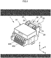
- FIGS. 1 to 25 An explanation will be given of a connector 1 according to an embodiment of the present disclosure with reference to FIGS. 1 to 25 .
- an XYZ coordinate system is defined, and will be referred as appropriate.
- the connector 1 is applied to, for example, electronic circuit components for an automobile, and has a Connector Position Assurance (CPA) function. As illustrated in FIGS. 1 and 2 , the connector 1 includes an outer housing 10, an inner housing 20, and a sliding member 30 (CPA member) that becomes able to slide upon engagement of both the outer housing 10 and the inner housing 20.
- CPA Connector Position Assurance
- the outer housing 10 is a housing of a receptacle connector mounted on a wiring board S.
- the outer housing 10 is formed of a plastic, and is formed by, for example, injection molding.
- the outer housing 10 is assembled with multiple male terminals 40.
- Each male terminal 40 is formed of a conductive material.
- the male terminal 40 has an end 40a at the +Y side and an end 40b at the -Y side both protruding from the outer housing 10.
- the end 40a of the male terminal 40 at the +Y side protrudes to the interior of an engagement opening 11 formed in the outer housing 10.
- the end 40b of the male terminal 40 at the -Y side is exposed from the rear end surface of the outer housing 10 at the -Y side, is curved in a substantially S-shape, and protrudes in parallel with the -Y direction.
- the end 40b of the male terminal 40 is applied as an external lead to be soldered to the wiring board S.
- the outer housing 10 is a member formed in a substantially box shape in which the engagement opening 11 opened in the +Y direction is formed.
- the inner housing 20 is to be fitted in the engagement opening 11 of the outer housing 10.
- a fitting direction D1 in which the inner housing 20 is fitted in the outer housing 10 is consistent with the -Y direction.
- the outer housing 10 includes an engagement catch 13.
- the engagement catch 13 is formed on a lower surface 12a of a ceiling wall 12 that is a part of wall defining the outer housing 10 at the nearby location to the +Y side.
- the engagement catch 13 includes, from the rear end side (+Y side) in the fitting direction D1 in sequence, an inclined surface 13a, a parallel surface 13b, and a standing-upright surface 13c.
- the inclined surface 13a includes a surface inclined relative to the fitting direction D1.
- the parallel surface 13b includes a parallel surface to the fitting direction D1.
- the standing-upright surface 13c includes a surface substantially in parallel with the Z-axis direction.
- the inner housing 20 is a housing of a plug connector to which wirings W are connected in this embodiment.
- the inner housing 20 is formed of a plastic, and is formed by, for example, injection molding. Multiple female terminals 50 are fitted in this inner housing 20.
- Each female terminal 50 is formed by, for example, bending a conductive sheet metal.
- a cylindrical part 51 which is formed in a substantially rectangular cylindrical shape, and in which the end 40a of each male terminal 40 at the +Y side is fitted is formed at the end of the female terminal 50 at the -Y side.
- the cylindrical part 51 includes an elastic contact piece to be in contact with the end 40a of the male terminal 40.
- the end 40a of the male terminal 40 fitted in the cylindrical part 51 is conductively fastened by the elastic force of the elastic contact piece of the cylindrical part 51.
- a binding part 52 that attaches and fastens the wirings W by pressure which are fitted therein is formed at the end of the female terminal 50 at the +Y side.
- the inner housing 20 is formed in a substantially cuboid shape that has the lengthwise direction substantially in parallel with the Y-axis direction. As illustrated in FIG. 4 , multiple terminal fitting openings 21 in which the respective female terminals 50 are fitted are formed in the rear end surface (the end surface at the +Y side) of the inner housing 20. As illustrated in FIG. 3 , each terminal fitting opening 21 is in communication with a terminal retaining room 22 formed inside the inner housing 20.
- the inner housing 20 includes an engagement latch 23, a latching release 24, ribs 25, and a pair of locking arms 60R, 60L.
- the engagement catch 13 of the outer housing 10 is to be latched by the engagement latch 23.
- the engagement latch 23 is provided between the locking arm 60R and the locking arm 60L so as to interlink the locking arm 60R with the locking arm 60L.
- the engagement latch 23 includes, from the leading end side (-Y side) in the fitting direction D1 of the inner housing 20 in sequence, an inclined surface 23a, an upper parallel surface 23b, a lower parallel surface 23d, and a standing-upright surface 23c.
- the inclined surface 23a includes an inclined surface relative to the fitting direction D 1.
- the upper parallel surface 23b and the lower parallel surface 23d are each include a plane.
- the inclined surface 23a and the upper parallel surface 23b are utilized as to-be-guided surfaces that are guided by the engagement catch 13 in accordance with the advancement of the engagement between the outer housing 10 and the inner housing 20.
- the standing-upright surface 23c includes a surface substantially in parallel with the Z-axis direction. When the standing-upright surface 23c faces the standing-upright surface 13c of the engagement catch 13, the latching between the engagement latch 23 and the engagement catch 13 completes.
- the lower parallel surface 23d is utilized as a guide surface that guides a protrusion 35 of the sliding member 30 in accordance with the sliding action of the sliding member 30.
- the engagement latch 23 is to be also latched by the protrusion 35 of the sliding member 30. Hence, the engagement latch 23 also serves as a protrusion catch.
- the latching release 24 is provided on the locking arms 60R, 60L. When a user depresses the latching release 24, the latching between the engagement latch 23 and the engagement catch 13 is released. This latching release enables the user to pull out the inner housing 20 from the outer housing 10.
- the ribs 25 are formed so as to improve the rigidity and strength of the inner housing 20.
- the ribs 25 are formed along the Y-axis direction.
- the locking arm 60R includes a leading-end-side locking arm part 61R, a parallel locking arm part 62R, and a rear-end-side locking arm part 63R.
- the leading-end-side locking arm part 61R is formed so as to extend in the vertical direction from the nearby location to the leading end part (-Y side end part) of a ceiling wall 26 that is a part of wall defining the inner housing 20.
- the leading-end-side locking arm part 61R may be extended in directions other than the vertical direction.
- the rear-end-side locking arm part 63R is extended in the vertical direction from the nearby location to the rear end part (+Y side end part) of the ceiling wall 26.
- the rear-end-side locking arm part 63R may be extended in directions other than the vertical direction.
- the parallel locking arm part 62R interlinks the leading-end-side locking arm part 61R with the rear-end-side locking arm part 63R, and is formed substantially in parallel with the Y-axis direction.
- the locking arm 60L employs the similar structure to that of the locking arm 60R. More specifically, as illustrated in FIG. 4 , the locking arm 60L includes a leading-end-side locking arm part 61L, a parallel locking arm part 62L, and a rear-end-side locking arm part 63L.
- the rear-end-side locking arm part 63L is extended in the vertical direction in this embodiment, but may be extended in directions other than the vertical direction.
- the locking arms 60R, 60L employing the above structure are formed so as to be deflectable in accordance with the advancement of engagement between the outer housing 10 and the inner housing 20.
- the inner housing 20 is provided with a slide channel 70 extended along the Y-axis direction, and rails 72 formed on the opposing surfaces of the respective ribs 25 facing with each other.
- the slide channel 70 allows the sliding member 30 to slide, and is formed so as to allow the sliding member 30 to pass through upon engagement between the two housings.
- the sliding passage 70 is provided at the upper side (+Z side) of the ceiling wall 26 of the inner housing 20.
- the sliding passage 70 is formed with a slide surface 71 that faces a lower surface 30a (the surface at the -Z side) of the sliding member 30 when the sliding member 30 slides.
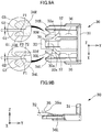
- FIGS. 6A and 6B are each a diagram for explaining the slide channel 70, and FIG. 6A is a cross-sectional view taken along a line A-A in FIG. 5 , while FIG. 6B is a cross-sectional view taken along a line B-B in FIG. 6A .
- FIG. 6B some structural components, such as the latching release 24, and the locking arms 60R, 60L, are omitted.
- the rear-end-side locking arm parts 63R, 63L are disposed at both sides of the slide channel 70, respectively.
- the slide surface 71 is formed with engagement parts 71a, 71b, and 71c.
- the engagement parts 71a, 71b, and 71c are each formed as a recess that has a bottom.
- the bottom surface of each engagement part 71 a, 71b, 71c is an offset surface from the slide surface 71 in the -Z direction, and is a parallel surface to the sliding surface 71.
- FIG. 7A is a cross-sectional view taken along the line A-A in FIG. 5 for explaining the rails 72.
- FIG. 7B is a cross-sectional view taken along a line C-C in FIG. 7A .
- the latching release 24, the locking arms 60R, 60L, and the like, are omitted.
- each rail 72 is formed so as to retract therein the rib 25, and is formed as a groove.
- Each rail 72 includes a first rail part 72A and a second rail part 72B that have different lateral cross-sectional areas (the area of the XZ cross-section) from each other.
- the first rail part 72A has the larger lateral cross-sectional area than that of the second rail part 72B.
- the rail 72 (more specifically, the first rail part 72A and the second rail part 72B) is formed in, as illustrated in FIG. 6B and FIG. 7B , a recess that includes a bottom surface 73, a first side surface 74, and a second side surface 75.
- the bottom surface 73 is a parallel surface to the YZ plane.
- the first side surface 74 forms a part of the slide surface 71.
- the first side surface 74 is a part of the slide surface 71
- the present disclosure is not limited to this example structure, and may be not a part of the slide surface 71.
- the second side surface 75 is formed so as to be inclined relative to the slide surface 71.
- the respective second side surfaces 75 of the first rail part 72A and the second rail part 72B have the substantially equal inclination angle to each other.
- a guide surface G4 that is inclined relative to the Y-axis direction.
- This guide surface G4 guides the fitting of the sliding member 30 into the inner housing 20 at the time of manufacturing and assembling of the connector 1 to improve the fitting easiness, thereby improving the assembling workability.
- the sliding member 30 serves as the CPA (Connector Position Assurance) member that locks the engagement between both the outer and inner housings 10, 20.
- the sliding member 30 is applied so as to allow the user to check whether or not the engagement between both the outer and inner housings 10, 20 is fully completed within the engagement work.
- the sliding member 30 includes a sliding member base 31, a main arm 32 protruding from the sliding member base 31, a pair of latching arms 33R, 33L, and a pair of support arms 34R, 34L.
- the sliding member base 31 is utilized as a depressed part to be depressed by the user when the user slides the sliding member 30.
- the main arm 32 is formed so as to protrude from the sliding member base 31 in the -Y direction.
- the protrusion 35 that protrudes upwardly (+Z direction).
- a rear end surface 35a of the protrusion 35 is formed as an inclined surface inclined in the Y-axis direction.
- the rear end surface 35a serves as a guide surface that guides the moving main arm 32 when the sliding member 30 is slid in the +Y direction.
- the latching arms 33R, 33L are formed so as to protrude from the sliding member base 31 in the -Y direction with the main arm 32 being present therebetween.
- the latching arms 33R, 33L are interlinked with the main arm 32 by an interlinking part 32a.
- the latching arms 33R, 33L include respective latches 36, and respective tentative latches 37.
- the rear-end-side locking arm parts 63R, 63L of the locking arms 60R, 60L are to be latched by the respective latches 36.
- the rear-end-side locking arm parts 63R, 63L each serve as a catch to be latched by the respective latches 36.
- the latches 36 are formed so as to protrude outwardly relative to each other. More specifically, the latches 36 are formed on the surface of the latching arm 33R at the -X side, and the surface of the latching arm 33L at the +X side.
- a surface 36a of the latch 36 at the -Y side and a surface 36b thereof at the +Y side are each formed as an inclined surface inclined in the Y-axis direction.
- the surfaces 36a, 36b of the respective latches 36 serve as guide surfaces that guide the rear-end-side locking arm parts 63R, 63L, respectively, while being in contact therewith when the sliding member 30 is slid in the -Y direction and in the +Y direction.
- the rear-end-side locking arm parts 63R, 63Lof the locking arms 60R, 60L are tentatively latched by the respective tentative latches 37.
- the rear-end-side locking arm parts 63R, 63L also serve as catches to be tentatively latched by the respective tentative latches 37.
- the tentative latches 37 prevents the sliding member 30 from moving in the +Y direction upon tentatively latching the rear-end-side locking arm parts 63R, 63L, respectively, thereby preventing the sliding member 30 from pulling out from the inner housing 20.
- the tentative latches 37 are formed in a shape protruding outwardly relative to each other like the respective latches 36.
- the tentative latches 37 are formed on the surface of the latching arm 33R at the -X side and on the surface of the latching arm 33L at the +X side. In addition, the tentative latches 37 are formed ahead of the respective latches 36 toward a leading end side (-Y side).
- respective guide surfaces G1 are formed at the leading end parts of the latching arms 33R, 33L.
- the guide surface G1 is formed as an inclined surface inclined in the Y-axis direction. This guide surface G1 is formed so as to improve the fitting easiness by guiding the fitting of the sliding member 30 into the inner housing 20 at the time of manufacturing and assembling of the connector 1, thereby improving the assembling workability.
- the support arms 34R, 34L are formed so as to protrude from the sliding member base 31 in the -Y direction with the latching arms 33R, 33L being present therebetween.
- the latching arms 34R, 34L each include a first support arm part 34A, and a second support arm part 34B extended from the rear end of the first support arm part 34A.
- the second support arm part 34B has a smaller lateral cross-sectional area (the area of the XZ cross-section) than that of the first support arm part 34A.
- the first support arm part 34A is formed so as to be engaged with the first rail part 72A of the rail 72.
- the second support arm part 34B is formed so as to be engaged with the second rail part 72B of the rail 72.
- the sliding member 30 and the inner housing 20 include the two engagement components, thereby enhancing the action of preventing the sliding member 30 from being detached from the inner housing 20.
- the support arms 34R, 34L each include an upper surface 30b (second surface) that faces the second side surface 75 of the rail 72 in a recess shape, and the lower surface 30a (first surface) that faces the first side surface 74 of the rail 72.
- the upper surface 30b is formed at the opposite side to the lower surface 30a, and is formed so as to be inclined relative to the slide surface 71.
- the respective upper surfaces 30b of the support arms 34R, 34L are formed so as to be inclined in the direction in which the support arms 34R, 34L face with each other.
- the inclination angle of the upper surface 30b is substantially equal to the corresponding inclination angle of the second side surface 75 of the rail 72.
- the upper surface 30b that is an inclination surface is formed on both the first support arm part 34A and the second support arm part 34B.
- guide surfaces G2, G3 are formed at the respective leading end parts of the support arms 34R, 34L.
- the guide surfaces G2, G3 are each formed as an inclined surface inclined in the Y-axis direction.
- Such guide surfaces G2, G3 are formed so as to improve the fitting easiness by guiding the fitting of the sliding member 30 into the inner housing 20 at the time of manufacturing and assembling of the connector 1, thereby improving the assembling workability.
- the latching arms 33R, 33L and the support arms 34R, 34L are formed in the substantially equal length. Hence, as is clear from the enlarged view that is FIG. 9A , the leading end parts of the latching arms 33R, 33L and those of the support arms 34R, 34L are located at the substantially consistent position in the lengthwise direction (Y-axis direction). Provided at the leading end parts of the latching arms 33R, 33L and those of the support arms 34R, 34L are protrusions P1, P2 protruding in the direction facing with each other.
- the protrusions P1, P2 are formed in a shape and a dimension that do not allow the main arm 32, the latching arms 33R, 33L, and the support arms 34R, 34L, and the like, to enter a gap C formed between the protrusion P1 and the protrusion P2. Hence, the protrusion P1 and the protrusion P2 prevent the sliding members 30 from getting caught each other at the time of manufacturing and assembling of the connector 1.
- FIG. 12 is a perspective view of the sliding member 30 as viewed from the lower side. As illustrated in FIG. 12 , a thickened part 38 that is raised up from the lower surface 30a basically planar is formed in the sliding member 30. In FIG. 12 , the thickened part 38 is indicated by multiple dots. The thickened part 38 is formed so as to increase the substantial thickness of the sliding member 30, thereby enhancing the strength thereof.
- the thickened part 38 includes a thickened piece 38a formed on the lower surface of the main arm 32, a thickened piece 38b formed on the lower surface of the support arm 34R, and a thickened piece 38c formed on the lower surface of the support arm 34L.
- the thickened piece 38a of the thickened part 38 is formed so as to be engaged with the engagement part 71a formed in the slide surface 71.
- the thickened pieces 38b, 38c are formed so as to be engaged with the engagement parts 71b, 71c, respectively.
- an offset surface 39 that is a plane is formed on each of the thickened pieces 38a to 38c at an offset position in the -Z direction relative to the lower surface 30a.
- Such offset surface 39 contacts the bottom of each engagement part 71a to 71c, and is slidable over such a bottom.
- FIG. 13 With the protrusion 35 formed at the main arm 32 latching the engagement latch 23 and having a sliding action restricted, the sliding member 30 is attached to the inner housing 20.
- the sliding member 30 in this stage is located at a first position (initial position) where the locking arms 60R, 60L are not latched by the latches 36 of the latching arms 33R, 33L, respectively, and the locking arms 60R, 60L are tentatively latched by the tentative latches 37.
- the standing-upright surface 23c of the engagement latch 23 reaches the standing-upright surface 13c of the engagement catch 13.
- the depression by the engagement latch 13 is canceled, and thus the deflection of the locking arms 60R, 60L is canceled.
- the engagement latch 23 is returned to the upper side (+Z side) based on the elastic recovery of the locking arms 60R, 60L as indicated by an arrow A3. Consequently, the standing-upright surface 23c and the standing-upright surface 13c face with each other, and the engagement catch 13 is latched by the engagement latch 23.
- the CPA (Connector Position Assurance) function of the connector 1 will be explained with reference to FIGS. 16 to 20 .
- the initial position of the sliding member 30 in FIG. 18A will be defined as the first position (stand-by position), and the position of the sliding member 30 after the movement illustrated in FIG. 18C will be defined as a second position (engagement locking position).
- the engagement latch 23 and the engagement catch 13 are not in a latched condition.
- the engagement latch 23 as a protrusion catch is latched by the protrusion 35.
- the sliding member 30 is in a condition in which the sliding action in the -Y direction is restricted.
- the engagement latch 23 moves upwardly (+Z side) and latches the engagement catch 13. Conversely, when the engagement latch 23 moves upwardly (+Z side), the latching between the protrusion 35 and the engagement latch 23 is released. Hence, the sliding member 30 becomes a condition capable of passing through the slide channel 70 in the -Y direction.
- the user who attempts to check the engagement condition between both the outer and inner housings 10, 20 moves the sliding member 30 from the first position (initial position) illustrated in FIG. 18A along the sliding channel 70. Note that the sliding direction D2 of the sliding member 30 is consistent with the -Y direction.
- the engagement latch 23 When the engagement latch 23 is latched by the protrusion 35, the main arm 32 is positioned below (-Z side) the engagement latch 23. Hence, the engagement latch 23 is not capable of moving by what corresponds to the amount necessary to cancel the engagement with the engagement catch 13, thus not capable of moving down to a position for canceling the engagement. Consequently, the engagement between the outer housing 10 and the inner housing 20 is locked by the sliding member 30.
- the sliding member 30 When the engagement between the outer housing 10 and the inner housing 20 is to be canceled, first, the sliding member 30 is moved from the second position (engagement locking position) illustrated in FIG. 23A to the first position (initial position) illustrated in FIG. 23C along a reverse sliding direction D4. Hence, the locking by the sliding member 30 is canceled, and a condition is accomplished in which the engagement between both the outer and inner housings 10, 20 can be canceled. Note that the reverse sliding direction D4 of the sliding member 30 is an opposite direction to the sliding direction D2.
- the latching release 24 of the inner housing 20 is pushed down as indicated by an arrow A9. This causes the locking arms 60R, 60L to be deflected, and as indicated by an arrow A10, the engagement latch 23 is pushed downwardly (-Z side). Consequently, the latching between the engagement latch 23 and the engagement catch 13 is canceled.
- the inner housing 20 is moved in the detaching direction D3, and is pulled out from the outer housing 10. Hence, the detachment of the inner housing 20 from the outer housing 10 completes. Note that when the inner housing 20 is detached from the outer housing 10, the deflection of the locking arms 60R, 60L is canceled, and the latching release 24 returns to the original position.
- the pair of latching arms 33R, 33L are deflected so as to decrease the gap therebetween by the depression from the locking arms 60R, 60L. This eliminates the necessary for ensuring the space by what corresponds to the deflection of the latching arms 33R, 33L in the inner housing 20 in the direction in which the gap increases. Consequently, the connector 1 can be downsized while accomplishing the connector position assurance function.
- the locking arms 60R, 60L serve as the catches to be latched by the latches 36 of the respective latching arms 33R, 33L.
- conventional connectors 1 that have no Connector Position Assurance (CPA) function also include the locking arms 60R, 60L.
- CPA Connector Position Assurance
- this connector can easily accomplish the connector position assurance function.
- an additional formation of a catch to be latched by the latch 36 in the inner housing 20 is unnecessary. Accordingly, the application of the sliding member 30 does not result in an increase in size of the connector 1. Consequently, the connector 1 can be downsized while accomplishing the connector position assurance function.
- the latching arms 33R, 33L are formed with the respective tentative latches 37.
- the locking arms 60R, 60L (more specifically, the rear-end-side locking arm parts 63R, 63L) are latched by such tentative latches 37, and thus the sliding member 30 is prevented from moving in the opposite direction (+Y direction) to the sliding direction D2.
- the detachment of the sliding member 30 from the inner housing 20 prior to the engagement can be prevented. Consequently, the work efficiency for the user who engages both the outer and inner housings 10, 20 is improved.
- the locking arms 60R, 60L serve as the catches to be tentatively latched by the tentative latches 37.
- an additional formation of the catch to be tentatively latched by the tentative latch 37 in the inner housing 20 is unnecessary.
- an increase in size of the connector 1 is unnecessary. Consequently, the downsizing of the connector 1 can be accomplished while accomplishing the connector position assurance function.
- the locking arms 60R, 60L are latched by both the latches 36 and the tentative latches 37, respectively. Since the locking arms 60R, 60L serve as the catches for both the latches 36 and the tentative latches 37, respectively, a separate formation of the catch for the latch 36 and of the catch for the tentative latch 37 is unnecessary. Hence, an increase in size of the connector 1 is unnecessary. Consequently, the downsizing of the connector 1 can be accomplished while accomplishing the connector position assurance function.
- the outer housing 10 is the housing of a receptacle connector to be mounted on the wiring board S, while the inner housing 20 is the housing of the plug connector to be connected with the wiring W.
- the present disclosure is not limited to this structure.
- both the connectors may include respective terminals, and the wirings W may be connected thereto.
- the rear-end-side locking arm parts 63R, 63L are extended in the vertical direction from the nearby location to the rear end (+Y side end) of the ceiling wall 26.
- the present disclosure is not limited to this structure.
- the rear-end-side locking arm parts 63R, 63L may be formed in the other shapes than that of the above embodiment as long as the latches 36 and the tentative latches 37 are capable of latching.
Landscapes
- Details Of Connecting Devices For Male And Female Coupling (AREA)
Abstract
Description
- This application relates generally to a connector.
-
Japan Patent No. 4657034 - In the connector disclosed in
Japan Patent No. 4657034 - The present disclosure has been made in view of the foregoing circumstances, and an objective is to accomplish a downsizing of a connector while accomplishing a connector position assurance function.
- In order to accomplish the above objective, a connector (1) according to an aspect of the present disclosure includes:
- a first housing (10) including an engagement catch (13);
- a second housing (20) including an engagement latch (23) to latch the engagement catch (13), a pair of locking arms (60R, 60L) each provided with the engagement latch (23), and a slide channel (70) having the pair of locking arms (60R, 60L) disposed at both sides, the second housing (20) being to be engaged with the first housing (10); and
- a sliding member (30) including a pair of arms (33R, 33L) each provided with a latch (36),
- in which:
- when the first housing (10) and the second housing (20) are engaged with each other, the first housing (10) and the second housing (20) may allow the sliding member (30) to pass through the slide channel (70); and
- when the sliding member (30) slides the slide channel (70), the pair of arms (33R, 33L) are deflected so as to decrease a gap therebetween by depressions from the respective locking arms (60R, 60L), and when the latches (36) go over the respective locking arms (60R, 60L), the gap between the pair of arms (33R, 33L) increases, the increase in the gap enabling the locking arms (60R, 60L) to be latched by the respective latches (36).
- The sliding member (30) may include a protrusion (35); and
the engagement latch (23) may be latched by the protrusion (35) to restrict a sliding action of the sliding member (30) until the engagement catch (13) is latched by the engagement latch (23) for the engagement between the first and second housings (10, 20), when the engagement catch (13) is latched by the engagement latch (23), the latching between the protrusion (35) and the engagement latch (23) may be canceled and the canceling of the latching between the protrusion (35) and the engagement latch (23) may enable the sliding member (30) to pass through the slide channel (70). - The pair of arms (33R, 33L) may each include a tentative latch (37) that prevents a movement in an opposite direction to the sliding action upon latching each of the locking arms (60R, 60L) of the second housing (20), and the tentative latch (37) may be provided ahead of the latch (36) toward a leading end.
- The respective latches (36) of the pair of arms (33R, 33L) may be formed in a shape protruding outwardly relative to each other.
- The respective first and second housings (10, 20) may be housings of the connector (1) that includes a terminal (40, 50) connected to a wiring (W).
- According to the present disclosure, the pair of arms (33R, 33L) are deflected so as to decrease the gap therebetween upon depression by the locking arm (60R, 60L). This eliminates the necessity of having a space in the second housing (20) by what corresponds to the deflection of the arms (33R, 33L) in the spreading direction. Consequently, a downsizing of the connector (1) is accomplished while also accomplishing a connector position assurance function.
- A more complete understanding of this application can be obtained when the following detailed description is considered in conjunction with the following drawings, in which:
-
FIG. 1 is a perspective view of a connector according to an embodiment of the present disclosure; -
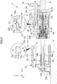
FIG. 2 is an exploded perspective view of the connector; -
FIG. 3 is an exploded YZ cross-sectional view of the connector; -
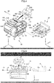
FIG. 4 is a perspective view of an inner housing and of a sliding member; -
FIG. 5 is a schematic cross-sectional view of the inner housing for explaining a slide channel; -
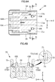
FIGS. 6A and 6B are each a diagram for explaining the slide channel, andFIG. 6A is a (first) cross-sectional view taken along a line A-A inFIG. 5 , whileFIG. 6B is a cross-sectional view taken along a line B-B inFIG. 6A ; -
FIGS. 7A and 7B are each a diagram for explaining a rail, andFIG. 7A is a (second) cross-sectional view taken along a line A-A inFIG. 5 , whileFIG. 7B is a cross-sectional view taken along a line C-C inFIG. 7A ; -
FIG. 8 is a (first) perspective view of the sliding member; -
FIG. 9A is a plan view of the sliding member, andFIG. 9B is a side view of the sliding member; -
FIG. 10A is a cross-sectional view taken along a line D-D inFIG. 5 , andFIG. 10B is an XY cross-sectional view of the sliding member disposed at a first position; -
FIG. 11A is an XY cross-sectional view of the sliding member disposed at a second position,FIG. 11B is a cross-sectional view taken along a line E-E inFIG. 11A, and FIG. 11C is a cross-sectional view taken along a line F-F inFIG. 11A ; -
FIG. 12 is a (second) perspective view of the sliding member; -
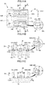
FIG. 13 is a (first) YZ cross-sectional view of the connector for explaining an engagement between an outer housing and an inner housing; -
FIG. 14 is a (second) YZ cross-sectional view of the connector for explaining the engagement between the outer housing and the inner housing; -
FIG. 15 is a (third) YZ cross-sectional view of the connector for explaining the engagement between the outer housing and the inner housing; -
FIG. 16 is a (fourth) YZ cross-sectional view of the connector for explaining the engagement between the outer housing and the inner housing; -
FIG. 17 is a (fifth) YZ cross-sectional view of the connector for explaining the engagement between the outer housing and the inner housing; -
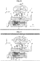
FIG. 18A is a (first) XY cross-sectional view of the sliding member, and the like, for explaining a Connector Position Assurance (CPA) function of the sliding member,FIG. 18B is a (second) XY cross-sectional view of the sliding member, and the like, for explaining the CPA function of the sliding member, andFIG. 18C is a (third) XY cross-sectional view of the sliding member, and the like, for explaining the CPA function; -
FIG. 19 is a (first) YZ cross-sectional view of the connector for explaining the CPA function of the sliding member; -
FIG. 20 is a (second) YZ cross-sectional view of the connector for explaining the CPA function of the sliding member; -
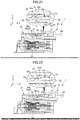
FIG. 21 is a (first) YZ cross-sectional view of the connector for explaining an action when the sliding member is slid in the reverse direction; -
FIG. 22 is a (second) YZ cross-sectional view of the connector for explaining an action when the sliding member is slid in the reverse direction; -
FIG. 23A is a (first) XY cross-sectional view of the sliding member, and the like, for explaining an action at the time of reverse sliding,FIG. 23B is a (second) XY cross-sectional view of the sliding member for explaining the action at the time of reverse sliding, andFIG. 23C is a (third) XY cross-sectional view of the sliding member, and the like, for explaining the action at the time of reverse sliding; -
FIG. 24 is a (third) YZ cross-sectional view of the connector for explaining the action when the sliding member is slid in the reverse direction; and -
FIG. 25 is a YZ cross-sectional view of the connector for explaining a disengagement between the outer housing and the inner housing. - An explanation will be given of a
connector 1 according to an embodiment of the present disclosure with reference toFIGS. 1 to 25 . In order to facilitate understanding, an XYZ coordinate system is defined, and will be referred as appropriate. - The
connector 1 is applied to, for example, electronic circuit components for an automobile, and has a Connector Position Assurance (CPA) function. As illustrated inFIGS. 1 and2 , theconnector 1 includes anouter housing 10, aninner housing 20, and a sliding member 30 (CPA member) that becomes able to slide upon engagement of both theouter housing 10 and theinner housing 20. - As illustrated in
FIG. 3 , in this embodiment, theouter housing 10 is a housing of a receptacle connector mounted on a wiring board S. Theouter housing 10 is formed of a plastic, and is formed by, for example, injection molding. Theouter housing 10 is assembled with multiplemale terminals 40. - Each
male terminal 40 is formed of a conductive material. Themale terminal 40 has anend 40a at the +Y side and anend 40b at the -Y side both protruding from theouter housing 10. Theend 40a of themale terminal 40 at the +Y side protrudes to the interior of anengagement opening 11 formed in theouter housing 10. Theend 40b of themale terminal 40 at the -Y side is exposed from the rear end surface of theouter housing 10 at the -Y side, is curved in a substantially S-shape, and protrudes in parallel with the -Y direction. Theend 40b of themale terminal 40 is applied as an external lead to be soldered to the wiring board S. - The
outer housing 10 is a member formed in a substantially box shape in which theengagement opening 11 opened in the +Y direction is formed. Theinner housing 20 is to be fitted in theengagement opening 11 of theouter housing 10. A fitting direction D1 in which theinner housing 20 is fitted in theouter housing 10 is consistent with the -Y direction. In addition, theouter housing 10 includes anengagement catch 13. - The
engagement catch 13 is formed on alower surface 12a of aceiling wall 12 that is a part of wall defining theouter housing 10 at the nearby location to the +Y side. Theengagement catch 13 includes, from the rear end side (+Y side) in the fitting direction D1 in sequence, aninclined surface 13a, aparallel surface 13b, and a standing-upright surface 13c. Theinclined surface 13a includes a surface inclined relative to the fitting direction D1. Theparallel surface 13b includes a parallel surface to the fitting direction D1. The standing-upright surface 13c includes a surface substantially in parallel with the Z-axis direction. - The
inner housing 20 is a housing of a plug connector to which wirings W are connected in this embodiment. Theinner housing 20 is formed of a plastic, and is formed by, for example, injection molding. Multiplefemale terminals 50 are fitted in thisinner housing 20. - Each
female terminal 50 is formed by, for example, bending a conductive sheet metal. Acylindrical part 51 which is formed in a substantially rectangular cylindrical shape, and in which theend 40a of eachmale terminal 40 at the +Y side is fitted is formed at the end of thefemale terminal 50 at the -Y side. Thecylindrical part 51 includes an elastic contact piece to be in contact with theend 40a of themale terminal 40. Theend 40a of themale terminal 40 fitted in thecylindrical part 51 is conductively fastened by the elastic force of the elastic contact piece of thecylindrical part 51. In addition, abinding part 52 that attaches and fastens the wirings W by pressure which are fitted therein is formed at the end of thefemale terminal 50 at the +Y side. - The
inner housing 20 is formed in a substantially cuboid shape that has the lengthwise direction substantially in parallel with the Y-axis direction. As illustrated inFIG. 4 , multiple terminalfitting openings 21 in which the respectivefemale terminals 50 are fitted are formed in the rear end surface (the end surface at the +Y side) of theinner housing 20. As illustrated inFIG. 3 , eachterminal fitting opening 21 is in communication with aterminal retaining room 22 formed inside theinner housing 20. - As illustrated in
FIGS. 3 ,4 , theinner housing 20 includes anengagement latch 23, a latchingrelease 24,ribs 25, and a pair of lockingarms - The
engagement catch 13 of theouter housing 10 is to be latched by theengagement latch 23. Theengagement latch 23 is provided between the lockingarm 60R and thelocking arm 60L so as to interlink thelocking arm 60R with the lockingarm 60L. Theengagement latch 23 includes, from the leading end side (-Y side) in the fitting direction D1 of theinner housing 20 in sequence, aninclined surface 23a, an upperparallel surface 23b, a lowerparallel surface 23d, and a standing-upright surface 23c. Theinclined surface 23a includes an inclined surface relative to thefitting direction D 1. The upperparallel surface 23b and the lowerparallel surface 23d are each include a plane. Theinclined surface 23a and the upperparallel surface 23b are utilized as to-be-guided surfaces that are guided by theengagement catch 13 in accordance with the advancement of the engagement between theouter housing 10 and theinner housing 20. The standing-upright surface 23c includes a surface substantially in parallel with the Z-axis direction. When the standing-upright surface 23c faces the standing-upright surface 13c of theengagement catch 13, the latching between theengagement latch 23 and theengagement catch 13 completes. The lowerparallel surface 23d is utilized as a guide surface that guides aprotrusion 35 of the slidingmember 30 in accordance with the sliding action of the slidingmember 30. - In addition, the
engagement latch 23 is to be also latched by theprotrusion 35 of the slidingmember 30. Hence, theengagement latch 23 also serves as a protrusion catch. - The latching
release 24 is provided on the lockingarms release 24, the latching between theengagement latch 23 and theengagement catch 13 is released. This latching release enables the user to pull out theinner housing 20 from theouter housing 10. - As illustrated in
FIG. 4 , theribs 25 are formed so as to improve the rigidity and strength of theinner housing 20. Theribs 25 are formed along the Y-axis direction. - As illustrated in
FIG. 5 , the lockingarm 60R includes a leading-end-sidelocking arm part 61R, a parallellocking arm part 62R, and a rear-end-sidelocking arm part 63R. In this embodiment, the leading-end-sidelocking arm part 61R is formed so as to extend in the vertical direction from the nearby location to the leading end part (-Y side end part) of aceiling wall 26 that is a part of wall defining theinner housing 20. However, the leading-end-sidelocking arm part 61R may be extended in directions other than the vertical direction. In this embodiment, the rear-end-sidelocking arm part 63R is extended in the vertical direction from the nearby location to the rear end part (+Y side end part) of theceiling wall 26. However, the rear-end-sidelocking arm part 63R may be extended in directions other than the vertical direction. The parallellocking arm part 62R interlinks the leading-end-sidelocking arm part 61R with the rear-end-sidelocking arm part 63R, and is formed substantially in parallel with the Y-axis direction. - The locking
arm 60L employs the similar structure to that of thelocking arm 60R. More specifically, as illustrated inFIG. 4 , the lockingarm 60L includes a leading-end-sidelocking arm part 61L, a parallellocking arm part 62L, and a rear-end-sidelocking arm part 63L. The rear-end-sidelocking arm part 63L is extended in the vertical direction in this embodiment, but may be extended in directions other than the vertical direction. - The locking
arms outer housing 10 and theinner housing 20. - In addition, as illustrated in
FIG. 4 , theinner housing 20 is provided with aslide channel 70 extended along the Y-axis direction, and rails 72 formed on the opposing surfaces of therespective ribs 25 facing with each other. - As illustrated in
FIG. 5 , theslide channel 70 allows the slidingmember 30 to slide, and is formed so as to allow the slidingmember 30 to pass through upon engagement between the two housings. The slidingpassage 70 is provided at the upper side (+Z side) of theceiling wall 26 of theinner housing 20. The slidingpassage 70 is formed with aslide surface 71 that faces alower surface 30a (the surface at the -Z side) of the slidingmember 30 when the slidingmember 30 slides. -
FIGS. 6A and 6B are each a diagram for explaining theslide channel 70, andFIG. 6A is a cross-sectional view taken along a line A-A inFIG. 5 , whileFIG. 6B is a cross-sectional view taken along a line B-B inFIG. 6A . InFIG. 6B , some structural components, such as the latchingrelease 24, and the lockingarms - As illustrated in
FIGS. 6A, 6B , the rear-end-sidelocking arm parts slide channel 70, respectively. In addition, theslide surface 71 is formed withengagement parts engagement parts engagement part slide surface 71 in the -Z direction, and is a parallel surface to the slidingsurface 71. -
FIG. 7A is a cross-sectional view taken along the line A-A inFIG. 5 for explaining therails 72.FIG. 7B is a cross-sectional view taken along a line C-C inFIG. 7A . InFIG. 7B , the latchingrelease 24, the lockingarms - As illustrated in
FIG. 7A , eachrail 72 is formed so as to retract therein therib 25, and is formed as a groove. Eachrail 72 includes afirst rail part 72A and asecond rail part 72B that have different lateral cross-sectional areas (the area of the XZ cross-section) from each other. Thefirst rail part 72A has the larger lateral cross-sectional area than that of thesecond rail part 72B. The rail 72 (more specifically, thefirst rail part 72A and thesecond rail part 72B) is formed in, as illustrated inFIG. 6B andFIG. 7B , a recess that includes abottom surface 73, afirst side surface 74, and asecond side surface 75. Thebottom surface 73 is a parallel surface to the YZ plane. In this embodiment, thefirst side surface 74 forms a part of theslide surface 71. In this embodiment, although thefirst side surface 74 is a part of theslide surface 71, the present disclosure is not limited to this example structure, and may be not a part of theslide surface 71. Thesecond side surface 75 is formed so as to be inclined relative to theslide surface 71. The respective second side surfaces 75 of thefirst rail part 72A and thesecond rail part 72B have the substantially equal inclination angle to each other. - In addition, as illustrated in
FIG. 6A , provided at a connection section between thefirst rail part 72A and thesecond rail part 72B is a guide surface G4 that is inclined relative to the Y-axis direction. This guide surface G4 guides the fitting of the slidingmember 30 into theinner housing 20 at the time of manufacturing and assembling of theconnector 1 to improve the fitting easiness, thereby improving the assembling workability. - The sliding
member 30 serves as the CPA (Connector Position Assurance) member that locks the engagement between both the outer andinner housings member 30 is applied so as to allow the user to check whether or not the engagement between both the outer andinner housings FIG. 8 , the slidingmember 30 includes a slidingmember base 31, amain arm 32 protruding from the slidingmember base 31, a pair of latchingarms support arms - The sliding
member base 31 is utilized as a depressed part to be depressed by the user when the user slides the slidingmember 30. - As illustrated in
FIGS. 9A, 9B , themain arm 32 is formed so as to protrude from the slidingmember base 31 in the -Y direction. Provided at the leading end of themain arm 32 is theprotrusion 35 that protrudes upwardly (+Z direction). Arear end surface 35a of theprotrusion 35 is formed as an inclined surface inclined in the Y-axis direction. Therear end surface 35a serves as a guide surface that guides the movingmain arm 32 when the slidingmember 30 is slid in the +Y direction. - The latching
arms member base 31 in the -Y direction with themain arm 32 being present therebetween. The latchingarms main arm 32 by aninterlinking part 32a. In addition, the latchingarms respective latches 36, and respective tentative latches 37. - As illustrated in
FIG. 11A , the rear-end-sidelocking arm parts arms locking arm parts latches 36 are formed so as to protrude outwardly relative to each other. More specifically, thelatches 36 are formed on the surface of thelatching arm 33R at the -X side, and the surface of thelatching arm 33L at the +X side. In addition, asurface 36a of thelatch 36 at the -Y side and asurface 36b thereof at the +Y side are each formed as an inclined surface inclined in the Y-axis direction. Thesurfaces respective latches 36 serve as guide surfaces that guide the rear-end-sidelocking arm parts member 30 is slid in the -Y direction and in the +Y direction. - As illustrated in
FIG. 10B , the rear-end-sidelocking arm parts 63R, 63Lof the lockingarms locking arm parts member 30 from moving in the +Y direction upon tentatively latching the rear-end-sidelocking arm parts member 30 from pulling out from theinner housing 20. The tentative latches 37 are formed in a shape protruding outwardly relative to each other like the respective latches 36. More specifically, thetentative latches 37 are formed on the surface of thelatching arm 33R at the -X side and on the surface of thelatching arm 33L at the +X side. In addition, thetentative latches 37 are formed ahead of therespective latches 36 toward a leading end side (-Y side). - Still further, as is clear from the enlarged view that is
FIG. 9A , respective guide surfaces G1 are formed at the leading end parts of the latchingarms member 30 into theinner housing 20 at the time of manufacturing and assembling of theconnector 1, thereby improving the assembling workability. - As illustrated in
FIG. 10A , thesupport arms member base 31 in the -Y direction with the latchingarms arms support arm part 34A, and a secondsupport arm part 34B extended from the rear end of the firstsupport arm part 34A. The secondsupport arm part 34B has a smaller lateral cross-sectional area (the area of the XZ cross-section) than that of the firstsupport arm part 34A. In addition, the firstsupport arm part 34A is formed so as to be engaged with thefirst rail part 72A of therail 72. Likewise, the secondsupport arm part 34B is formed so as to be engaged with thesecond rail part 72B of therail 72. As explained above, the slidingmember 30 and theinner housing 20 include the two engagement components, thereby enhancing the action of preventing the slidingmember 30 from being detached from theinner housing 20. - As illustrated in
FIGS. 11B, 11C , thesupport arms upper surface 30b (second surface) that faces thesecond side surface 75 of therail 72 in a recess shape, and thelower surface 30a (first surface) that faces thefirst side surface 74 of therail 72. Theupper surface 30b is formed at the opposite side to thelower surface 30a, and is formed so as to be inclined relative to theslide surface 71. In addition, the respectiveupper surfaces 30b of thesupport arms support arms support arms respective rails 72 that are respective grooves, the slidingmember 30 is prevented from being detached from theinner housing 20. The inclination angle of theupper surface 30b is substantially equal to the corresponding inclination angle of thesecond side surface 75 of therail 72. Theupper surface 30b that is an inclination surface is formed on both the firstsupport arm part 34A and the secondsupport arm part 34B. - As is clear from the enlarged view that is
FIG. 9A , guide surfaces G2, G3 are formed at the respective leading end parts of thesupport arms member 30 into theinner housing 20 at the time of manufacturing and assembling of theconnector 1, thereby improving the assembling workability. - The latching
arms support arms FIG. 9A , the leading end parts of the latchingarms support arms arms support arms main arm 32, the latchingarms support arms members 30 from getting caught each other at the time of manufacturing and assembling of theconnector 1. -
FIG. 12 is a perspective view of the slidingmember 30 as viewed from the lower side. As illustrated inFIG. 12 , a thickenedpart 38 that is raised up from thelower surface 30a basically planar is formed in the slidingmember 30. InFIG. 12 , the thickenedpart 38 is indicated by multiple dots. The thickenedpart 38 is formed so as to increase the substantial thickness of the slidingmember 30, thereby enhancing the strength thereof. - In this embodiment, the thickened
part 38 includes a thickenedpiece 38a formed on the lower surface of themain arm 32, a thickenedpiece 38b formed on the lower surface of thesupport arm 34R, and a thickenedpiece 38c formed on the lower surface of thesupport arm 34L. As illustrated inFIG. 11B that is a cross-sectional end view taken along a line E-E, the thickenedpiece 38a of the thickenedpart 38 is formed so as to be engaged with theengagement part 71a formed in theslide surface 71. Likewise, the thickenedpieces engagement parts surface 39 that is a plane is formed on each of the thickenedpieces 38a to 38c at an offset position in the -Z direction relative to thelower surface 30a. Such offsetsurface 39 contacts the bottom of eachengagement part 71a to 71c, and is slidable over such a bottom. - An explanation will be given of how to engage the
outer housing 10 of theconnector 1 employing the above structure with theinner housing 20 thereof with reference toFIGS. 13 to 17 . As illustrated inFIG. 13 , with theprotrusion 35 formed at themain arm 32 latching theengagement latch 23 and having a sliding action restricted, the slidingmember 30 is attached to theinner housing 20. In addition, as illustrated inFIG. 18A , the slidingmember 30 in this stage is located at a first position (initial position) where the lockingarms latches 36 of the latchingarms arms - As illustrated in
FIG. 14 , when theinner housing 20 is being fitted in theengagement opening 11 of theouter housing 10 together with the slidingmember 30 in the fitting direction D1, theengagement latch 23 abuts theengagement catch 13. In addition, the leading end part of theend 40a of eachmale terminal 40 enters thecylindrical part 51 of eachfemale terminal 50. - As illustrated in
FIG. 15 , when theinner housing 20 is further fitted in theengagement opening 11 of theouter housing 10, theengagement latch 23 is guided by theinclined surface 13a of theengagement catch 13 together with theprotrusion 35 of the slidingmember 30. This guiding by theinclined surface 13a causes the lockingarms inner housing 20 and themain arm 32 of the slidingmember 30 to be deflected. Next, by the depression from theengagement catch 13, as indicated by an arrow A1, theengagement latch 23 and theprotrusion 35 are pushed downwardly (-Z side). - As illustrated in
FIG. 16 , when theinner housing 20 is further fitted in theengagement opening 11 of theouter housing 10, theengagement latch 23 is guided by theparallel surface 13b of theengagement catch 13, thus being moved in the -Y direction together with theprotrusion 35 of the slidingmember 30 as indicated by an arrow A2. - As illustrated in
FIG. 17 , when theinner housing 20 is further fitted in theengagement opening 11 of theouter housing 10, the standing-upright surface 23c of theengagement latch 23 reaches the standing-upright surface 13c of theengagement catch 13. When the standing-upright surface 23c reaches the standing-upright surface 13c, the depression by theengagement latch 13 is canceled, and thus the deflection of the lockingarms engagement latch 23 is returned to the upper side (+Z side) based on the elastic recovery of the lockingarms upright surface 23c and the standing-upright surface 13c face with each other, and theengagement catch 13 is latched by theengagement latch 23. - At the time point at which the
engagement catch 13 is latched by theengagement latch 23, theprotrusion 35 is still being guided by theparallel surface 13b. Hence, the deflection of themain arm 32 is not canceled yet. - Through the above actions, the engagement between the
outer housing 10 of theconnector 1 and theinner housing 20 thereof completes. In addition, upon completion of the engagement between both the outer andinner housings end 40a of eachmale terminal 40 into thecylindrical part 51 of eachfemale terminal 50 also completes, and thus eachmale terminal 40 and eachfemale terminal 50 are electrically connected to each other. - Next, the CPA (Connector Position Assurance) function of the
connector 1 will be explained with reference toFIGS. 16 to 20 . The initial position of the slidingmember 30 inFIG. 18A will be defined as the first position (stand-by position), and the position of the slidingmember 30 after the movement illustrated inFIG. 18C will be defined as a second position (engagement locking position). - As illustrated in
FIG. 16 , when the engagement between both the outer andinner housings engagement latch 23 and theengagement catch 13 are not in a latched condition. In addition, theengagement latch 23 as a protrusion catch is latched by theprotrusion 35. Hence, the slidingmember 30 is in a condition in which the sliding action in the -Y direction is restricted. - As illustrated in
FIG. 17 , when the engagement between both the outer andinner housings engagement latch 23 moves upwardly (+Z side) and latches theengagement catch 13. Conversely, when theengagement latch 23 moves upwardly (+Z side), the latching between theprotrusion 35 and theengagement latch 23 is released. Hence, the slidingmember 30 becomes a condition capable of passing through theslide channel 70 in the -Y direction. - When the engagement between both the outer and
inner housings inner housings member 30 from the first position (initial position) illustrated inFIG. 18A along the slidingchannel 70. Note that the sliding direction D2 of the slidingmember 30 is consistent with the -Y direction. - When the sliding
member 30 is being slid, as illustrated inFIG. 19 , theprotrusion 35 of the slidingmember 30 moves from theparallel surface 13b of theengagement catch 13 to the lowerparallel surface 23d of theengagement latch 23, and is guided by the lowerparallel surface 23d, and thus the slidingmember 30 is moved in parallel with the -Y direction. In addition, as illustrated inFIG. 18A , when the slidingmember 30 is moved in parallel with the -Y direction, therespective latches 36 of the slidingmember 30 abut the lockingarms locking arm parts - In addition, as illustrated in
FIG. 18B , when the slidingmember 30 is further slid, thelatches 36 are guided by the lockingarms arms arms arms - Yet still further, as illustrated in
FIG. 18C , when the slidingmember 30 is further slid, thelatches 36 go over the lockingarms arms arms arms FIG. 20 , theprotrusion 35 goes over theengagement latch 23, and thus the deflection of themain arm 32 is canceled. Still further, based on the elastic recovery by themain arm 32, as indicated by an arrow A5, theprotrusion 35 is returned upwardly (+Z side). Consequently, theengagement latch 23 is latched by theprotrusion 35. - When the
engagement latch 23 is latched by theprotrusion 35, themain arm 32 is positioned below (-Z side) theengagement latch 23. Hence, theengagement latch 23 is not capable of moving by what corresponds to the amount necessary to cancel the engagement with theengagement catch 13, thus not capable of moving down to a position for canceling the engagement. Consequently, the engagement between theouter housing 10 and theinner housing 20 is locked by the slidingmember 30. - Through the above actions, the movement of the sliding
member 30 from the first position (initial position) illustrated inFIG. 18A to the second position (engagement locking position) illustrated inFIG. 18C completes. The user who pushes the slidingmember 30 in the second position becomes able to check whether or not the engagement between both the outer andinner housings - Next, an explanation will be given of how to detach the
inner housing 20 of theconnector 1 from theouter housing 10 thereof with reference toFIGS. 21 to 25 . As illustrated inFIG. 25 , the direction in which theinner housing 20 is pulled out from the outer housing 10 (detaching direction D3) is consistent with the +Y direction. - When the engagement between the
outer housing 10 and theinner housing 20 is to be canceled, first, the slidingmember 30 is moved from the second position (engagement locking position) illustrated inFIG. 23A to the first position (initial position) illustrated inFIG. 23C along a reverse sliding direction D4. Hence, the locking by the slidingmember 30 is canceled, and a condition is accomplished in which the engagement between both the outer andinner housings member 30 is an opposite direction to the sliding direction D2. - When the sliding
member 30 is further slid in the reverse sliding direction D4, as illustrated inFIG. 21 , therear end surface 35a of theprotrusion 35 of the slidingmember 30 is guided by theengagement latch 23. Next, as is indicated by an arrow A6, theprotrusion 35 moves downwardly (-Z side), and thus themain arm 32 of the slidingmember 30 is deflected. Consequently, as illustrated inFIG. 22 , the latching between theprotrusion 35 and theengagement latch 23 is canceled. - In addition, as illustrated in
FIG. 23A , when the slidingmember 30 is further slid in the reverse sliding direction D4, as illustrated inFIG. 23B , thelatches 36 of the slidingmember 30 are guided by therespective locking arms arms arms - Still further, as illustrated in
FIG. 23C , when the slidingmember 30 is further slid, thelatches 36 go over the lockingarms arms arms arms respective laches 36 and the respectivetentative latches 37, and the lockingarms tentative laches 37, respectively. This tentative latching restricts a further sliding action of the slidingmember 30 in the +Y direction. - Yet still further, as illustrated in
FIG. 24 , when the slidingmember 30 is further slid, as indicated by an arrow A8, theprotrusion 35 moves from the lowerparallel surface 23d of theengagement latch 23 to theparallel surface 13b of theengagement catch 13. Hence, a space where none of members is present is created below theengagement latch 23, and the move-down amount for theengagement latch 23 necessary to fully cancel the latching with theengagement catch 13 is ensured. Consequently, the engagement between both the outer andinner housings - Next, as illustrated in
FIG. 25 , the latchingrelease 24 of theinner housing 20 is pushed down as indicated by an arrow A9. This causes the lockingarms engagement latch 23 is pushed downwardly (-Z side). Consequently, the latching between theengagement latch 23 and theengagement catch 13 is canceled. - Subsequently, the
inner housing 20 is moved in the detaching direction D3, and is pulled out from theouter housing 10. Hence, the detachment of theinner housing 20 from theouter housing 10 completes. Note that when theinner housing 20 is detached from theouter housing 10, the deflection of the lockingarms release 24 returns to the original position. - As explained above, according to this embodiment, as illustrated in
FIG. 18B , the pair of latchingarms arms arms inner housing 20 in the direction in which the gap increases. Consequently, theconnector 1 can be downsized while accomplishing the connector position assurance function. - In addition, according to this embodiment, the locking
arms latches 36 of the respective latchingarms conventional connectors 1 that have no Connector Position Assurance (CPA) function also include the lockingarms member 30 in this embodiment to such aconnector 1 that has no connector position assurance function, this connector can easily accomplish the connector position assurance function. In addition, in order to apply the slidingmember 30 in this embodiment, an additional formation of a catch to be latched by thelatch 36 in theinner housing 20 is unnecessary. Accordingly, the application of the slidingmember 30 does not result in an increase in size of theconnector 1. Consequently, theconnector 1 can be downsized while accomplishing the connector position assurance function. - Still further, since an additional formation of the catch to be latched by the latching
arms inner housing 20 is unnecessary, an increase in manufacturing costs of theconnector 1 can be prevented. - Yet still further, according to this embodiment, as illustrated in
FIG. 18A , the latchingarms arms locking arm parts tentative latches 37, and thus the slidingmember 30 is prevented from moving in the opposite direction (+Y direction) to the sliding direction D2. Hence, the detachment of the slidingmember 30 from theinner housing 20 prior to the engagement can be prevented. Consequently, the work efficiency for the user who engages both the outer andinner housings - In addition, the locking
arms tentative latch 37 in theinner housing 20 is unnecessary. Hence, an increase in size of theconnector 1 is unnecessary. Consequently, the downsizing of theconnector 1 can be accomplished while accomplishing the connector position assurance function. - The locking
arms latches 36 and thetentative latches 37, respectively. Since the lockingarms latches 36 and thetentative latches 37, respectively, a separate formation of the catch for thelatch 36 and of the catch for thetentative latch 37 is unnecessary. Hence, an increase in size of theconnector 1 is unnecessary. Consequently, the downsizing of theconnector 1 can be accomplished while accomplishing the connector position assurance function. - The embodiment of the present disclosure has been explained above, but the present disclosure is not limited to the above embodiment.
- For example, according to the above embodiment of the present disclosure, the
outer housing 10 is the housing of a receptacle connector to be mounted on the wiring board S, while theinner housing 20 is the housing of the plug connector to be connected with the wiring W. However, the present disclosure is not limited to this structure. For example, both the connectors may include respective terminals, and the wirings W may be connected thereto. - In addition, in the above embodiment, the rear-end-side
locking arm parts ceiling wall 26. However, the present disclosure is not limited to this structure. The rear-end-sidelocking arm parts latches 36 and thetentative latches 37 are capable of latching. - The foregoing describes some example embodiments for explanatory purposes. Accordingly, the specification and drawings are to be regarded in an illustrative rather than a restrictive sense. This detailed description, therefore, is not to be taken in a limiting sense, and the scope of the invention is defined only by the included claims, along with the full range of equivalents to which such claims are entitled.
- 1
- Connector
- 10
- Outer housing (First housing)
- 11
- Engagement opening
- 12
- Ceiling wall
- 12a
- Lower surface
- 13
- Engagement catch
- 13a
- Inclined surface
- 13b
- Parallel surface
- 13c
- Standing-upright surface
- 20
- Inner housing (Second housing)
- 21
- Terminal fitting opening
- 22
- Terminal retaining room
- 23
- Engagement latch (Protrusion catch)
- 23a
- Inclined surface
- 23b
- Upper parallel surface
- 23c
- Standing-upright surface
- 23d
- Lower parallel surface
- 24
- Latching release
- 25
- Rib
- 26
- Ceiling wall
- 30
- Sliding member
- 30a
- Lower surface
- 30b
- Upper surface
- 31
- Sliding member base
- 32
- Main arm
- 32a
- Interlinking part
- 33R, 33L
- Latching arm (Arm)
- 34R, 34L
- Support arm
- 34A
- First support arm part
- 34B
- Second support arm part
- 35
- Protrusion
- 35a
- Rear end surface
- 36
- Latch
- 36a, 36b
- Surface
- 37
- Tentative latch
- 38
- Thickened part
- 38a, 38b, 38c
- Thickened piece
- 39
- Offset surface
- 40
- Male terminal
- 40a, 40b
- End
- 50
- Female terminal
- 51
- Cylindrical part
- 52
- Binding part
- 60R,
- 60L Locking arm
- 61R, 61L
- Leading-end-side locking arm part
- 62R, 62L
- Parallel locking arm part
- 63R, 63L
- Rear-end-side locking arm part
- 70
- Slide channel
- 71
- Slide surface
- 71a, 71b, 71c
- Engagement part
- 72
- Rails
- 72A
- First rail part
- 72B
- Second rail part
- 73
- Bottom surface
- 74
- First side surface
- 75
- Second side surface
- S
- Wiring board
- W
- Wiring
- G1-G4
- Guide surface
- P1, P2
- Protrusion
- D1
- Fitting direction
- D2
- Sliding direction
- D3
- Detaching direction
- D4
- Reverse sliding direction
Claims (5)
- A connector (1) characterized by comprising:a first housing (10) comprising an engagement catch (13);a second housing (20) comprising an engagement latch (23) to latch the engagement catch (13), a pair of locking arms (60R, 60L) each provided with the engagement latch (23), and a slide channel (70) having the pair of locking arms (60R, 60L) disposed at both sides, the second housing (20) being to be engaged with the first housing (10); anda sliding member (30) comprising a pair of arms (33R, 33L) each provided with a latch (36),wherein:when the first housing (10) and the second housing (20) are engaged with each other, the first housing (10) and the second housing (20) allow the sliding member (30) to pass through the slide channel (70); andwhen the sliding member (30) slides the slide channel (70), the pair of arms (33R, 33L) are deflected so as to decrease a gap therebetween by depressions from the respective locking arms (60R, 60L), and when the latches (36) go over the respective locking arms (60R, 60L), the gap between the pair of arms (33R, 33L) increases, the increase in the gap enabling the locking arms (60R, 60L) to be latched by the respective latches (36).
- The connector (1) according to claim 1, characterized in that:the sliding member (30) comprises a protrusion (35); andthe engagement latch (23) is latched by the protrusion (35) to restrict a sliding action of the sliding member (30) until the engagement catch (13) is latched by the engagement latch (23) for the engagement between the first and second housings (10, 20), when the engagement catch (13) is latched by the engagement latch (23), the latching between the protrusion (35) and the engagement latch (23) is canceled and the canceling of the latching between the protrusion (35) and the engagement latch (23) enables the sliding member (30) to pass through the slide channel (70).
- The connector (1) according to claim 1 or 2, characterized in that the pair of arms (33R, 33L) each comprise a tentative latch (37) that prevents a movement in an opposite direction to the sliding action upon latching each of the locking arms (60R, 60L) of the second housing (20), the tentative latch (37) being provided ahead of the latch (36) toward a leading end.
- The connector (1) according to any one of claims 1 to 3, characterized in that the respective latches (36) of the pair of arms (33R, 33L) are formed in a shape protruding outwardly relative to each other.
- The connector (1) according to any one of claims 1 to 4, characterized in that the respective first and second housings (10, 20) are housings of the connector (1) that comprises a terminal (40, 50) connected to a wiring (W).
Applications Claiming Priority (1)
| Application Number | Priority Date | Filing Date | Title |
|---|---|---|---|
| JP2016034895A JP6213590B2 (en) | 2016-02-25 | 2016-02-25 | connector |
Publications (2)
| Publication Number | Publication Date |
|---|---|
| EP3211729A1 true EP3211729A1 (en) | 2017-08-30 |
| EP3211729B1 EP3211729B1 (en) | 2018-09-26 |
Family
ID=58108503
Family Applications (1)
| Application Number | Title | Priority Date | Filing Date |
|---|---|---|---|
| EP17157290.2A Not-in-force EP3211729B1 (en) | 2016-02-25 | 2017-02-22 | Electrical connector |
Country Status (5)
| Country | Link |
|---|---|
| US (1) | US10014620B2 (en) |
| EP (1) | EP3211729B1 (en) |
| JP (1) | JP6213590B2 (en) |
| KR (1) | KR101886954B1 (en) |
| CN (1) | CN107123900B (en) |
Cited By (2)
| Publication number | Priority date | Publication date | Assignee | Title |
|---|---|---|---|---|
| WO2019178053A1 (en) | 2018-03-12 | 2019-09-19 | J.S.T. Corporation | Connector position assurance member |
| EP3706254A1 (en) * | 2019-03-04 | 2020-09-09 | Aptiv Technologies Limited | High voltage electrical connector with cpa assembled on slider |
Families Citing this family (19)
| Publication number | Priority date | Publication date | Assignee | Title |
|---|---|---|---|---|
| JP6417369B2 (en) * | 2016-07-29 | 2018-11-07 | 矢崎総業株式会社 | connector |
| JP6717273B2 (en) | 2017-08-07 | 2020-07-01 | 株式会社デンソー | Head up display device |
| US10135172B1 (en) * | 2018-03-23 | 2018-11-20 | Te Connectivity Corporation | Connector position assurance member |
| US10340632B1 (en) | 2018-06-06 | 2019-07-02 | Lear Corporation | Electrical connector assembly with staged release |
| JP7123678B2 (en) * | 2018-07-23 | 2022-08-23 | 矢崎総業株式会社 | connector |
| CN209045863U (en) * | 2018-10-19 | 2019-06-28 | 矢崎(中国)投资有限公司 | Therminal retainer and connector |
| JP6865725B2 (en) * | 2018-10-31 | 2021-04-28 | 矢崎総業株式会社 | connector |
| US10505314B1 (en) * | 2018-11-02 | 2019-12-10 | Te Connectivity Corporation | Electrical connector with a connector position assurance member for a shrouded latch |
| US10566726B1 (en) * | 2018-11-29 | 2020-02-18 | Lear Corporation | Connector with sliding terminal position assurance |
| JP6996487B2 (en) * | 2018-12-25 | 2022-01-17 | 株式会社オートネットワーク技術研究所 | connector |
| DE102020102604A1 (en) * | 2019-02-01 | 2020-08-06 | Hirschmann Automotive Gmbh | Plug connection with improved locking element |
| JP2020161360A (en) * | 2019-03-27 | 2020-10-01 | 住友電装株式会社 | connector |
| WO2021010262A1 (en) | 2019-07-18 | 2021-01-21 | タイコエレクトロニクスジャパン合同会社 | Connector |
| CN110504590B (en) * | 2019-07-30 | 2021-01-29 | 中航光电科技股份有限公司 | Push-pull locking connector |
| JP7398238B2 (en) * | 2019-10-17 | 2023-12-14 | 矢崎総業株式会社 | connector |
| CN111370922B (en) * | 2020-03-24 | 2021-06-29 | 中航光电科技股份有限公司 | Connector and connector assembly |
| CN113471763B (en) * | 2020-03-31 | 2024-02-13 | 泰科电子(上海)有限公司 | Connector assembly |
| KR102313402B1 (en) * | 2020-05-25 | 2021-10-15 | 주식회사 경신 | Connector |
| JP7469180B2 (en) * | 2020-08-11 | 2024-04-16 | 矢崎総業株式会社 | connector |
Citations (5)
| Publication number | Priority date | Publication date | Assignee | Title |
|---|---|---|---|---|
| EP0655807A2 (en) * | 1993-11-30 | 1995-05-31 | The Whitaker Corporation | Connector position assurance device |
| EP1369964A1 (en) * | 2002-03-06 | 2003-12-10 | Tyco Electronics Corporation | Connector Position Assurance Device |
| WO2009047744A2 (en) * | 2007-10-12 | 2009-04-16 | Fci | Electrical connector assembly having connector position assurance device |
| JP4657034B2 (en) | 2005-07-08 | 2011-03-23 | 三菱電線工業株式会社 | connector |
| WO2013092310A1 (en) * | 2011-12-23 | 2013-06-27 | Delphi Connection Systems Holding France | Electrical connectors assembly with connector positionning assurance |
Family Cites Families (5)
| Publication number | Priority date | Publication date | Assignee | Title |
|---|---|---|---|---|
| CA2277682C (en) | 1998-07-30 | 2007-12-04 | Osram Sylvania Inc. | Connector module |
| JP4103333B2 (en) * | 2000-12-28 | 2008-06-18 | 住友電装株式会社 | Connector and continuity inspection method in connector |
| JP2005251540A (en) * | 2004-03-03 | 2005-09-15 | Japan Aviation Electronics Industry Ltd | Connector device |
| JP5831818B2 (en) * | 2012-03-09 | 2015-12-09 | 住友電装株式会社 | connector |
| US8678846B2 (en) * | 2012-03-28 | 2014-03-25 | Tyco Electronics Corporation | Electrical connector with connector position assurance device |
-
2016
- 2016-02-25 JP JP2016034895A patent/JP6213590B2/en not_active Expired - Fee Related
-
2017
- 2017-02-13 US US15/431,598 patent/US10014620B2/en active Active
- 2017-02-22 EP EP17157290.2A patent/EP3211729B1/en not_active Not-in-force
- 2017-02-23 KR KR1020170024346A patent/KR101886954B1/en active IP Right Grant
- 2017-02-24 CN CN201710104118.2A patent/CN107123900B/en not_active Expired - Fee Related
Patent Citations (5)
| Publication number | Priority date | Publication date | Assignee | Title |
|---|---|---|---|---|
| EP0655807A2 (en) * | 1993-11-30 | 1995-05-31 | The Whitaker Corporation | Connector position assurance device |
| EP1369964A1 (en) * | 2002-03-06 | 2003-12-10 | Tyco Electronics Corporation | Connector Position Assurance Device |
| JP4657034B2 (en) | 2005-07-08 | 2011-03-23 | 三菱電線工業株式会社 | connector |
| WO2009047744A2 (en) * | 2007-10-12 | 2009-04-16 | Fci | Electrical connector assembly having connector position assurance device |
| WO2013092310A1 (en) * | 2011-12-23 | 2013-06-27 | Delphi Connection Systems Holding France | Electrical connectors assembly with connector positionning assurance |
Cited By (5)
| Publication number | Priority date | Publication date | Assignee | Title |
|---|---|---|---|---|
| WO2019178053A1 (en) | 2018-03-12 | 2019-09-19 | J.S.T. Corporation | Connector position assurance member |
| WO2019177977A1 (en) | 2018-03-12 | 2019-09-19 | J.S.T. Corporation | Electric connector with cpa |
| EP3766139A4 (en) * | 2018-03-12 | 2021-12-01 | J.S.T. Corporation | Electric connector with cpa |
| EP3766135A4 (en) * | 2018-03-12 | 2022-01-05 | J.S.T. Corporation | Connector position assurance member |
| EP3706254A1 (en) * | 2019-03-04 | 2020-09-09 | Aptiv Technologies Limited | High voltage electrical connector with cpa assembled on slider |
Also Published As
| Publication number | Publication date |
|---|---|
| EP3211729B1 (en) | 2018-09-26 |
| JP6213590B2 (en) | 2017-10-18 |
| US10014620B2 (en) | 2018-07-03 |
| CN107123900B (en) | 2019-05-03 |
| JP2017152272A (en) | 2017-08-31 |
| KR101886954B1 (en) | 2018-08-08 |
| CN107123900A (en) | 2017-09-01 |
| US20170250492A1 (en) | 2017-08-31 |
| KR20170100442A (en) | 2017-09-04 |
Similar Documents
| Publication | Publication Date | Title |
|---|---|---|
| EP3211729B1 (en) | Electrical connector | |
| EP3211730A1 (en) | Electrical connector | |
| EP3211731A1 (en) | Electrical connector | |
| US9935396B2 (en) | Connector having first and second housings and a sliding member implementing a connector position assurance function | |
| EP1936749B1 (en) | A terminal fitting, a connector and a forming method | |
| EP2362498B1 (en) | Male and female connectors and electrical connector including the same | |
| US7918682B2 (en) | Connector system for a vehicle antenna | |
| US10367290B2 (en) | Connector device and male connector | |
| JP7090584B2 (en) | Connector housing and terminal position guarantee joint clip site | |
| US20070054537A1 (en) | Connector with a shorting terminal | |
| CN214227247U (en) | Connector assembly | |
| JP2009048861A (en) | Electrical connector | |
| JP5836623B2 (en) | connector | |
| JP4175774B2 (en) | connector | |
| KR102707012B1 (en) | Connector | |
| JP2011243539A (en) | Connector with positive lock mechanism | |
| JP2008204724A (en) | Locking lance, and lance locking structure | |
| TW201431195A (en) | Connector |
Legal Events
| Date | Code | Title | Description |
|---|---|---|---|
| PUAI | Public reference made under article 153(3) epc to a published international application that has entered the european phase |
Free format text: ORIGINAL CODE: 0009012 |
|
| STAA | Information on the status of an ep patent application or granted ep patent |
Free format text: STATUS: REQUEST FOR EXAMINATION WAS MADE |
|
| 17P | Request for examination filed |
Effective date: 20170222 |
|
| AK | Designated contracting states |
Kind code of ref document: A1 Designated state(s): AL AT BE BG CH CY CZ DE DK EE ES FI FR GB GR HR HU IE IS IT LI LT LU LV MC MK MT NL NO PL PT RO RS SE SI SK SM TR |
|
| AX | Request for extension of the european patent |
Extension state: BA ME |
|
| RBV | Designated contracting states (corrected) |
Designated state(s): AL AT BE BG CH CY CZ DE DK EE ES FI FR GB GR HR HU IE IS IT LI LT LU LV MC MK MT NL NO PL PT RO RS SE SI SK SM TR |
|
| GRAP | Despatch of communication of intention to grant a patent |
Free format text: ORIGINAL CODE: EPIDOSNIGR1 |
|
| STAA | Information on the status of an ep patent application or granted ep patent |
Free format text: STATUS: GRANT OF PATENT IS INTENDED |
|
| INTG | Intention to grant announced |
Effective date: 20180417 |
|
| GRAS | Grant fee paid |
Free format text: ORIGINAL CODE: EPIDOSNIGR3 |
|
| GRAA | (expected) grant |
Free format text: ORIGINAL CODE: 0009210 |
|
| STAA | Information on the status of an ep patent application or granted ep patent |
Free format text: STATUS: THE PATENT HAS BEEN GRANTED |
|
| AK | Designated contracting states |
Kind code of ref document: B1 Designated state(s): AL AT BE BG CH CY CZ DE DK EE ES FI FR GB GR HR HU IE IS IT LI LT LU LV MC MK MT NL NO PL PT RO RS SE SI SK SM TR |
|
| REG | Reference to a national code |
Ref country code: GB Ref legal event code: FG4D |
|
| REG | Reference to a national code |
Ref country code: CH Ref legal event code: EP |
|
| REG | Reference to a national code |
Ref country code: AT Ref legal event code: REF Ref document number: 1047136 Country of ref document: AT Kind code of ref document: T Effective date: 20181015 |
|
| REG | Reference to a national code |
Ref country code: IE Ref legal event code: FG4D |
|
| REG | Reference to a national code |
Ref country code: DE Ref legal event code: R096 Ref document number: 602017000490 Country of ref document: DE |
|
| REG | Reference to a national code |
Ref country code: DE Ref legal event code: R082 Ref document number: 602017000490 Country of ref document: DE Representative=s name: SSM SANDMAIR PATENTANWAELTE RECHTSANWALT PARTN, DE |
|
| REG | Reference to a national code |
Ref country code: NL Ref legal event code: MP Effective date: 20180926 |
|
| PG25 | Lapsed in a contracting state [announced via postgrant information from national office to epo] |
Ref country code: NO Free format text: LAPSE BECAUSE OF FAILURE TO SUBMIT A TRANSLATION OF THE DESCRIPTION OR TO PAY THE FEE WITHIN THE PRESCRIBED TIME-LIMIT Effective date: 20181226 Ref country code: GR Free format text: LAPSE BECAUSE OF FAILURE TO SUBMIT A TRANSLATION OF THE DESCRIPTION OR TO PAY THE FEE WITHIN THE PRESCRIBED TIME-LIMIT Effective date: 20181227 Ref country code: FI Free format text: LAPSE BECAUSE OF FAILURE TO SUBMIT A TRANSLATION OF THE DESCRIPTION OR TO PAY THE FEE WITHIN THE PRESCRIBED TIME-LIMIT Effective date: 20180926 Ref country code: BG Free format text: LAPSE BECAUSE OF FAILURE TO SUBMIT A TRANSLATION OF THE DESCRIPTION OR TO PAY THE FEE WITHIN THE PRESCRIBED TIME-LIMIT Effective date: 20181226 Ref country code: LT Free format text: LAPSE BECAUSE OF FAILURE TO SUBMIT A TRANSLATION OF THE DESCRIPTION OR TO PAY THE FEE WITHIN THE PRESCRIBED TIME-LIMIT Effective date: 20180926 Ref country code: RS Free format text: LAPSE BECAUSE OF FAILURE TO SUBMIT A TRANSLATION OF THE DESCRIPTION OR TO PAY THE FEE WITHIN THE PRESCRIBED TIME-LIMIT Effective date: 20180926 |
|
| REG | Reference to a national code |
Ref country code: LT Ref legal event code: MG4D |
|
| PG25 | Lapsed in a contracting state [announced via postgrant information from national office to epo] |
Ref country code: HR Free format text: LAPSE BECAUSE OF FAILURE TO SUBMIT A TRANSLATION OF THE DESCRIPTION OR TO PAY THE FEE WITHIN THE PRESCRIBED TIME-LIMIT Effective date: 20180926 Ref country code: LV Free format text: LAPSE BECAUSE OF FAILURE TO SUBMIT A TRANSLATION OF THE DESCRIPTION OR TO PAY THE FEE WITHIN THE PRESCRIBED TIME-LIMIT Effective date: 20180926 Ref country code: AL Free format text: LAPSE BECAUSE OF FAILURE TO SUBMIT A TRANSLATION OF THE DESCRIPTION OR TO PAY THE FEE WITHIN THE PRESCRIBED TIME-LIMIT Effective date: 20180926 |
|
| REG | Reference to a national code |
Ref country code: AT Ref legal event code: MK05 Ref document number: 1047136 Country of ref document: AT Kind code of ref document: T Effective date: 20180926 |
|
| PG25 | Lapsed in a contracting state [announced via postgrant information from national office to epo] |
Ref country code: RO Free format text: LAPSE BECAUSE OF FAILURE TO SUBMIT A TRANSLATION OF THE DESCRIPTION OR TO PAY THE FEE WITHIN THE PRESCRIBED TIME-LIMIT Effective date: 20180926 Ref country code: NL Free format text: LAPSE BECAUSE OF FAILURE TO SUBMIT A TRANSLATION OF THE DESCRIPTION OR TO PAY THE FEE WITHIN THE PRESCRIBED TIME-LIMIT Effective date: 20180926 Ref country code: PL Free format text: LAPSE BECAUSE OF FAILURE TO SUBMIT A TRANSLATION OF THE DESCRIPTION OR TO PAY THE FEE WITHIN THE PRESCRIBED TIME-LIMIT Effective date: 20180926 Ref country code: IS Free format text: LAPSE BECAUSE OF FAILURE TO SUBMIT A TRANSLATION OF THE DESCRIPTION OR TO PAY THE FEE WITHIN THE PRESCRIBED TIME-LIMIT Effective date: 20190126 Ref country code: ES Free format text: LAPSE BECAUSE OF FAILURE TO SUBMIT A TRANSLATION OF THE DESCRIPTION OR TO PAY THE FEE WITHIN THE PRESCRIBED TIME-LIMIT Effective date: 20180926 Ref country code: CZ Free format text: LAPSE BECAUSE OF FAILURE TO SUBMIT A TRANSLATION OF THE DESCRIPTION OR TO PAY THE FEE WITHIN THE PRESCRIBED TIME-LIMIT Effective date: 20180926 Ref country code: AT Free format text: LAPSE BECAUSE OF FAILURE TO SUBMIT A TRANSLATION OF THE DESCRIPTION OR TO PAY THE FEE WITHIN THE PRESCRIBED TIME-LIMIT Effective date: 20180926 Ref country code: EE Free format text: LAPSE BECAUSE OF FAILURE TO SUBMIT A TRANSLATION OF THE DESCRIPTION OR TO PAY THE FEE WITHIN THE PRESCRIBED TIME-LIMIT Effective date: 20180926 Ref country code: IT Free format text: LAPSE BECAUSE OF FAILURE TO SUBMIT A TRANSLATION OF THE DESCRIPTION OR TO PAY THE FEE WITHIN THE PRESCRIBED TIME-LIMIT Effective date: 20180926 |
|
| PG25 | Lapsed in a contracting state [announced via postgrant information from national office to epo] |
Ref country code: SK Free format text: LAPSE BECAUSE OF FAILURE TO SUBMIT A TRANSLATION OF THE DESCRIPTION OR TO PAY THE FEE WITHIN THE PRESCRIBED TIME-LIMIT Effective date: 20180926 Ref country code: SM Free format text: LAPSE BECAUSE OF FAILURE TO SUBMIT A TRANSLATION OF THE DESCRIPTION OR TO PAY THE FEE WITHIN THE PRESCRIBED TIME-LIMIT Effective date: 20180926 Ref country code: PT Free format text: LAPSE BECAUSE OF FAILURE TO SUBMIT A TRANSLATION OF THE DESCRIPTION OR TO PAY THE FEE WITHIN THE PRESCRIBED TIME-LIMIT Effective date: 20190126 |
|
| REG | Reference to a national code |
Ref country code: DE Ref legal event code: R097 Ref document number: 602017000490 Country of ref document: DE |
|
| PG25 | Lapsed in a contracting state [announced via postgrant information from national office to epo] |
Ref country code: DK Free format text: LAPSE BECAUSE OF FAILURE TO SUBMIT A TRANSLATION OF THE DESCRIPTION OR TO PAY THE FEE WITHIN THE PRESCRIBED TIME-LIMIT Effective date: 20180926 |
|
| PLBE | No opposition filed within time limit |
Free format text: ORIGINAL CODE: 0009261 |
|
| STAA | Information on the status of an ep patent application or granted ep patent |
Free format text: STATUS: NO OPPOSITION FILED WITHIN TIME LIMIT |
|
| 26N | No opposition filed |
Effective date: 20190627 |
|
| PG25 | Lapsed in a contracting state [announced via postgrant information from national office to epo] |
Ref country code: SI Free format text: LAPSE BECAUSE OF FAILURE TO SUBMIT A TRANSLATION OF THE DESCRIPTION OR TO PAY THE FEE WITHIN THE PRESCRIBED TIME-LIMIT Effective date: 20180926 Ref country code: MC Free format text: LAPSE BECAUSE OF FAILURE TO SUBMIT A TRANSLATION OF THE DESCRIPTION OR TO PAY THE FEE WITHIN THE PRESCRIBED TIME-LIMIT Effective date: 20180926 Ref country code: LU Free format text: LAPSE BECAUSE OF NON-PAYMENT OF DUE FEES Effective date: 20190222 |
|
| REG | Reference to a national code |
Ref country code: BE Ref legal event code: MM Effective date: 20190228 |
|
| REG | Reference to a national code |
Ref country code: IE Ref legal event code: MM4A |
|
| PG25 | Lapsed in a contracting state [announced via postgrant information from national office to epo] |
Ref country code: IE Free format text: LAPSE BECAUSE OF NON-PAYMENT OF DUE FEES Effective date: 20190222 |
|
| PG25 | Lapsed in a contracting state [announced via postgrant information from national office to epo] |
Ref country code: BE Free format text: LAPSE BECAUSE OF NON-PAYMENT OF DUE FEES Effective date: 20190228 |
|
| PG25 | Lapsed in a contracting state [announced via postgrant information from national office to epo] |
Ref country code: TR Free format text: LAPSE BECAUSE OF FAILURE TO SUBMIT A TRANSLATION OF THE DESCRIPTION OR TO PAY THE FEE WITHIN THE PRESCRIBED TIME-LIMIT Effective date: 20180926 |
|
| PG25 | Lapsed in a contracting state [announced via postgrant information from national office to epo] |
Ref country code: MT Free format text: LAPSE BECAUSE OF NON-PAYMENT OF DUE FEES Effective date: 20190222 |
|
| REG | Reference to a national code |
Ref country code: CH Ref legal event code: PL |
|
| PG25 | Lapsed in a contracting state [announced via postgrant information from national office to epo] |
Ref country code: LI Free format text: LAPSE BECAUSE OF NON-PAYMENT OF DUE FEES Effective date: 20200229 Ref country code: CH Free format text: LAPSE BECAUSE OF NON-PAYMENT OF DUE FEES Effective date: 20200229 |
|
| PGFP | Annual fee paid to national office [announced via postgrant information from national office to epo] |
Ref country code: FR Payment date: 20210226 Year of fee payment: 5 |
|
| PG25 | Lapsed in a contracting state [announced via postgrant information from national office to epo] |
Ref country code: CY Free format text: LAPSE BECAUSE OF FAILURE TO SUBMIT A TRANSLATION OF THE DESCRIPTION OR TO PAY THE FEE WITHIN THE PRESCRIBED TIME-LIMIT Effective date: 20180926 |
|
| PG25 | Lapsed in a contracting state [announced via postgrant information from national office to epo] |
Ref country code: SE Free format text: LAPSE BECAUSE OF NON-PAYMENT OF DUE FEES Effective date: 20180926 |
|
| PG25 | Lapsed in a contracting state [announced via postgrant information from national office to epo] |
Ref country code: HU Free format text: LAPSE BECAUSE OF FAILURE TO SUBMIT A TRANSLATION OF THE DESCRIPTION OR TO PAY THE FEE WITHIN THE PRESCRIBED TIME-LIMIT; INVALID AB INITIO Effective date: 20170222 |
|
| GBPC | Gb: european patent ceased through non-payment of renewal fee |
Effective date: 20210222 |
|
| PG25 | Lapsed in a contracting state [announced via postgrant information from national office to epo] |
Ref country code: GB Free format text: LAPSE BECAUSE OF NON-PAYMENT OF DUE FEES Effective date: 20210222 |
|
| PGFP | Annual fee paid to national office [announced via postgrant information from national office to epo] |
Ref country code: DE Payment date: 20220217 Year of fee payment: 6 |
|
| PG25 | Lapsed in a contracting state [announced via postgrant information from national office to epo] |
Ref country code: MK Free format text: LAPSE BECAUSE OF FAILURE TO SUBMIT A TRANSLATION OF THE DESCRIPTION OR TO PAY THE FEE WITHIN THE PRESCRIBED TIME-LIMIT Effective date: 20180926 |
|
| PG25 | Lapsed in a contracting state [announced via postgrant information from national office to epo] |
Ref country code: FR Free format text: LAPSE BECAUSE OF NON-PAYMENT OF DUE FEES Effective date: 20220228 |
|
| REG | Reference to a national code |
Ref country code: DE Ref legal event code: R119 Ref document number: 602017000490 Country of ref document: DE |
|
| PG25 | Lapsed in a contracting state [announced via postgrant information from national office to epo] |
Ref country code: DE Free format text: LAPSE BECAUSE OF NON-PAYMENT OF DUE FEES Effective date: 20230901 |