EP0655807A2 - Connector position assurance device - Google Patents
Connector position assurance device Download PDFInfo
- Publication number
- EP0655807A2 EP0655807A2 EP94308098A EP94308098A EP0655807A2 EP 0655807 A2 EP0655807 A2 EP 0655807A2 EP 94308098 A EP94308098 A EP 94308098A EP 94308098 A EP94308098 A EP 94308098A EP 0655807 A2 EP0655807 A2 EP 0655807A2
- Authority
- EP
- European Patent Office
- Prior art keywords
- connector
- position assurance
- assurance device
- mating
- locking arm
- Prior art date
- Legal status (The legal status is an assumption and is not a legal conclusion. Google has not performed a legal analysis and makes no representation as to the accuracy of the status listed.)
- Withdrawn
Links
Images


Classifications
-
- H—ELECTRICITY
- H01—ELECTRIC ELEMENTS
- H01R—ELECTRICALLY-CONDUCTIVE CONNECTIONS; STRUCTURAL ASSOCIATIONS OF A PLURALITY OF MUTUALLY-INSULATED ELECTRICAL CONNECTING ELEMENTS; COUPLING DEVICES; CURRENT COLLECTORS
- H01R13/00—Details of coupling devices of the kinds covered by groups H01R12/70 or H01R24/00 - H01R33/00
- H01R13/62—Means for facilitating engagement or disengagement of coupling parts or for holding them in engagement
- H01R13/639—Additional means for holding or locking coupling parts together, after engagement, e.g. separate keylock, retainer strap
-
- H—ELECTRICITY
- H01—ELECTRIC ELEMENTS
- H01R—ELECTRICALLY-CONDUCTIVE CONNECTIONS; STRUCTURAL ASSOCIATIONS OF A PLURALITY OF MUTUALLY-INSULATED ELECTRICAL CONNECTING ELEMENTS; COUPLING DEVICES; CURRENT COLLECTORS
- H01R13/00—Details of coupling devices of the kinds covered by groups H01R12/70 or H01R24/00 - H01R33/00
- H01R13/64—Means for preventing incorrect coupling
- H01R13/641—Means for preventing incorrect coupling by indicating incorrect coupling; by indicating correct or full engagement
-
- H—ELECTRICITY
- H01—ELECTRIC ELEMENTS
- H01R—ELECTRICALLY-CONDUCTIVE CONNECTIONS; STRUCTURAL ASSOCIATIONS OF A PLURALITY OF MUTUALLY-INSULATED ELECTRICAL CONNECTING ELEMENTS; COUPLING DEVICES; CURRENT COLLECTORS
- H01R13/00—Details of coupling devices of the kinds covered by groups H01R12/70 or H01R24/00 - H01R33/00
- H01R13/62—Means for facilitating engagement or disengagement of coupling parts or for holding them in engagement
- H01R13/627—Snap or like fastening
- H01R13/6271—Latching means integral with the housing
- H01R13/6272—Latching means integral with the housing comprising a single latching arm
-
- H—ELECTRICITY
- H01—ELECTRIC ELEMENTS
- H01R—ELECTRICALLY-CONDUCTIVE CONNECTIONS; STRUCTURAL ASSOCIATIONS OF A PLURALITY OF MUTUALLY-INSULATED ELECTRICAL CONNECTING ELEMENTS; COUPLING DEVICES; CURRENT COLLECTORS
- H01R13/00—Details of coupling devices of the kinds covered by groups H01R12/70 or H01R24/00 - H01R33/00
- H01R13/64—Means for preventing incorrect coupling
Definitions
- This invention relates to an electrical connector which is matable to another connector.
- the invention is directed to an electrical connector which has a connector position assurance device that can only be moved to a fully inserted position when the connectors are completely mated.
- U.S. Patent 4,370,013 is directed to a lock member which is designed to assure that a pair of male and female electrical connectors, which are initially fully coupled and positively locked together by a manual assembly operation, remain locked by means of the lock member.
- the lock member avoids the problem of the electrical connectors being decoupled by vibration or some other environmental influence during subsequent use and, in effect, is intended to prevent, without disclosure of the fact, the disassembly of the connectors.
- U.S. Patent 4,634,204 discloses two connectors, which when mated, have a connector position assurance and assist device inserted axially along a tracked slot. If the connectors are only partially interconnected, upon initial insertion of the connector position assurance and assist device though the connector it will assist the two connectors to become fully and rigidly mated, whereas if the device is improperly inserted into the connector it will refuse the further mating of the connectors.
- U.S. Patent 5,120,255 teaches of a complete locking confirming device for confirming the complete locking of an electrical connector assembly.
- the device has a locking detector slider mounted on either housing so as to be positioned at an indicating position only when the housings are coupled completely.
- the invention is directed to a connector position assurance device for use with mating connectors.
- the connector position assurance device has a locking arm which extends from a body portion.
- the locking arm is stiff and is dimensioned to cooperate with a respective portion of a first mating connector.
- At least one latching arm cooperates with the mating connectors to movably maintain the connector position assurance device on a respective connector.
- the at least one latching arm being movable between a first and a second position.
- the invention is also directed to an electrical connector which has a mating face which cooperates with a mating connector.
- a resilient primary latch is positioned on the electrical connector and is used to latch the mating connector to the electrical connector.
- the primary latch is provided proximate a connector position assurance receiving area of the electrical connector.
- the connector position assurance receiving area has barbs extending therein.
- a connector position assurance device is positioned in the connector position assurance receiving area, and has a locking arm and latching arms.
- the latching arms cooperate with the barbs to movably maintain the connector position assurance device in the connector position assurance receiving area.
- the latching arms cooperate with the barbs to movably maintain the connector position assurance device in the connector position assurance receiving area.
- the locking arm cooperates with the primary latch, when the locking arm is in a fully inserted position, to prevent the resilient movement of the primary latch.
- a first electrical connector 10 is shown.
- the particular connector shown has a mating face 12 and a wire receiving face 14.
- Contact receiving cavities 16 extend from proximate the mating face to proximate the wire receiving face 14.
- the contact receiving cavities are dimensioned to receive contacts (not shown) therein. It should be noted that the configuration of the housing may vary according to the application.
- a connector position assurance receiving area 20 is provided proximate a top surface of the first connector 10.
- the receiving area 20 has a shroud 22 provided proximate the mating face 12.
- the shroud is dimensioned to receive a portion of a mating connector (not shown) therein.
- the receiving area 20 has opposed side walls 24, 26 which extend rearward to proximate the wire receiving face 14.
- Each of the side walls has a cavity 28 provided therein.
- the cavities extend from the wire receiving face 14 toward the mating face 12, and are essentially parallel to the axis of the contact receiving cavities 16.
- the primary latch 30 has two spaced apart resilient arms 32 which are joined at the free end thereof by a cross member (not shown). Intermediate the fixed ends and the free ends of the resilient arms 32 is an engagement member 36.
- Connector position assurance device 50 has a connector locking arm 52, a main body portion 54, an engagement portion 56, latching arms 58, and stabilization members 60.
- the latching arms 58 are provided on each side of the main body portion 54 and are positioned such that the longitudinal axis of the arms are essentially parallel to the longitudinal axis of the locking arm 52.
- the latching arms are spaced from the main body portion to allow the free ends 62 thereof to be resiliently deformed.
- Each latching arm 54 has a first angled surface 70 proximate the free end 62, a first locking shoulder 72, a second angled surface 74 and a second locking shoulder 76.
- Stabilization members 60 extend in a direction which is essentially perpendicular to connector locking arm 52.
- the members 60 are cylindrical in configuration and have an enlarged free end portion 78.
- the enlarged free end portion has a larger diameter than the remainder of the stabilization member.
- the particular connector 110 has a mating face 112 and a wire receiving face 114.
- Contact receiving cavities 116 extend from proximate the mating face 112 to proximate the wire receiving face 114.
- the contact receiving cavities are dimensioned to receive contacts (not shown) therein.
- a connector position assurance receiving area 120 is provided proximate a top surface of the first connector 110.
- the receiving area 120 has a shroud 122 provided proximate the mating face 112.
- the shroud is dimensioned to receive a portion of a mating connector 118 therein.
- the receiving area 120 has opposed side walls 124, 126 ( Figure 4) which extend rearward proximate the wire receiving face 114.
- the primary latch 110 has two spaced apart resilient arms 132 which are joined at the free end thereof by a cross member 134. Intermediate the fixed ends and the free ends of the resilient arms 132 is an engagement member 136.
- Connector position assurance device 150 has a connector locking arm 152, a main body portion 154, an engagement portion 156, and latching arms 158.
- the latching arms 158 are provided on each side of the main body portion 154 and are positioned such that the longitudinal axis of the arms are essentially parallel to the longitudinal axis of the locking arm 152. Referring to Figure 5, the latching arms are spaced from the main body portion to allow the free ends 162 thereof to be resiliently deformed.
- Each latching arm 154 has a first angled surface 170 proximate the free end 162, a first locking shoulder 172, a second angled surface 174 and a second locking shoulder 176.
- Figures 5 through 10 show connector position assurance devices 150 prior to insertion into the first electrical connector 110.
- the device 150 is inserted into the connector 110 and is maintained in an initial position, as shown in Figure 7.
- the first angled surfaces 170 of the latching arms 158 cooperate with barbs 138 to cause the latching arms to deform resiliently inward.
- the latching arms continue to move relative to the barbs 138, causing the first locking shoulders 172 to move beyond the barbs.
- the latch arms 158 resiliently return to their unstressed position, thereby capturing the barbs 138 between the first locking shoulders 172 and the second angled surface 174. This defines the initial position.
- the mating connector 118 can be mated to connector 110.
- a latch 180 of connector 118 cooperates with latch 130 of connector 110.
- a connector latch receiving end of latch 180 engages the cross member 134 of latch 130. This engagement causes the primary latch 130 to resiliently deform, as shown in Figure 8.
- the positioning of the device 150 in the first position aligns the device 150 with slots provided in the primary latch 130, thereby allowing the resilient movement of the latch.
- the device 150 is moved to the fully inserted or final position.
- the connector locking arm 152 is positioned under the cross member 134 of latch 130.
- the locking arm 152 is made of relatively thick plastic and therefore, does not have resilient characteristics.
- the locking arm 152 is also supported by a support member 168 of connector 110, to prevent the locking arm 152 from deforming downward. Consequently, the positioning of the locking arm under the cross member prevents the resilient movement of the latch 130 and ensures that the connectors 110 and 118 will be maintained in a mated position.
- latch 130 will be deformed as shown in Figure 8, which prevents the movement of the device 150 to its final position. Consequently, if the connectors are not properly mated, the device 150 cannot be fully inserted, providing a visual indication that the mating is inadequate.
- the operator grasps the engagement portion 156 and pulls the contact position assurance device 150 in a direction opposed to the direction of insertion. As this occurs, the barbs 138 cause the latching arms 158 to deform resiliently inward.
- the force required to move the device 150 from the final position to the initial position is determined by the angle of the second locking shoulder 176 (i.e. the steeper the slope of the shoulder, the more force required).
- the removal of the device 150 continues until the latching arms return to the unstressed position, causing the first locking shoulders 172 to engage the barbs 138. As the shoulders 172 are essentially perpendicular to the longitudinal axis of the latching arms, the force required to remove the device beyond the initial position will damage the connector position assurance device.
- connector position assurance device 50 shown in Figures 1 through 3 is essentially the same as that described above.
- device 50 has stabilization members 60 which are positioned in cavities 28, as shown in Figure 3.
- the enlarged free end portions 78 are spaced apart a distance which is slightly greater than the distance between side walls 24, 26. The cooperation of the enlarged end portions 78 with side walls 24, 26 ensure that the connector assurance device 50 will be properly inserted, i.e. the device 50 will not be skewed or rotated as it is moved relative to the connector 10.
- Figures 11 through 15 disclose another embodiment of a connector position assurance device 250. This embodiment has many of the same features as connector 150 described above.
- the locking arm 252 has an anti-overstress projection 290 which extends from proximate a free end thereof in a downward direction as viewed in Figures 11 through 14. As best shown in Figure 15, the width of projection 290 is less than the width of the locking arm 252.
- the free end when the locking arm 252 is in an unstressed position, the free end is offset in the direction from the fixed end. In the figures, the free end is upwardly offset from the fixed end. This offset can be accomplished in various ways including molding the locking arm in this "bent" configuration or bending the locking arm after molding to cause the locking arm to take a permanent set.
- a slot 294 is positioned in the receiving area 220 of the connector 210.
- the slot is dimensioned to be slightly larger than projection 290, as is shown in Figure 15.
- the anti-overstress projection 290 is positioned in the slot 294 and slides therein.
- the positioning of the projection in the slot provides a guide and centering means which ensures that the free end of the locking arm 252 will be properly positioned in the receiving area 220 of the connector 210.
- surfaces of the locking arm cooperate with the support member 268 to adequately support the locking arm.
- the connector position assurance device 250 is maintained in the initial and final positions in the manner described above. However, the device 250 cannot be moved to the final position until mating connector 218 is fully mated to connector 210. As shown in Figure 11, if the device 250 is moved toward the final position before the mating connector is properly positioned, the offset free end of the locking arm 252 will engage the cross member 234 of the primary latch 230, thereby preventing the movement of the device 250 into the final position.
- the latch 280 of the mating connector cooperates with the latch 230, as shown in Figure 12.
- a connector latch receiving end of the latch 280 engages the cross member 234, causing the primary latch 230 to resiliently pivot.
- the positioning of the device 250 in the first position aligns the device 250 with slots provided in the primary latch 230 as the latch pivots.
- the latch 280 moves past the cross member 234, thereby allowing the primary latch 230 to return to its unstressed position. As this occurs, the latch 280 engages the free end of the locking arm 252 of the device 250. As the insertion continues, the locking arm 252 is moved downward to the position shown in Figure 13. In this position, the latch has deformed the locking arm 252.
- the connector position assurance device With the mating connector 218 fully inserted and the locking arm deformed, the connector position assurance device is moved to the final position.
- the device 250 is able to move beyond the cross member 234 because the latch 280 maintains the free end of the arm 252 in a position below the cross member 234.
- the removal of the mating connector from the connector is prevented unless the connector position assurance device has been moved to the initial position.
- the anti-overstress projection 290 will engage a top surface of the mating connector when a downward force is applied to the primary latch.
- the height of the anti-overstress projection is approximately equal to the space provided between the latch and the top surface, the downward movement of the cross member 234 is essentially prevented, thereby preventing the removal of the mating connector 218 from the connector 210. Therefore, in order to remove the mating connector 218, the device 250 is moved to the initial position, the primary latch 230 is depressed, and the mating connector is removed. This prevents the unwanted removal of the mating connector due to harsh environments or operator error.
Landscapes
- Details Of Connecting Devices For Male And Female Coupling (AREA)
Abstract
Description
- This invention relates to an electrical connector which is matable to another connector. In particular, the invention is directed to an electrical connector which has a connector position assurance device that can only be moved to a fully inserted position when the connectors are completely mated.
- U.S. Patent 4,370,013 is directed to a lock member which is designed to assure that a pair of male and female electrical connectors, which are initially fully coupled and positively locked together by a manual assembly operation, remain locked by means of the lock member. The lock member avoids the problem of the electrical connectors being decoupled by vibration or some other environmental influence during subsequent use and, in effect, is intended to prevent, without disclosure of the fact, the disassembly of the connectors.
- U.S. Patent 4,634,204 discloses two connectors, which when mated, have a connector position assurance and assist device inserted axially along a tracked slot. If the connectors are only partially interconnected, upon initial insertion of the connector position assurance and assist device though the connector it will assist the two connectors to become fully and rigidly mated, whereas if the device is improperly inserted into the connector it will refuse the further mating of the connectors.
- U.S. Patent 5,120,255 teaches of a complete locking confirming device for confirming the complete locking of an electrical connector assembly. The device has a locking detector slider mounted on either housing so as to be positioned at an indicating position only when the housings are coupled completely.
- The above references teach electrical connectors which have some type of connector position assurance member. However, it would be beneficial to provide electrical connectors with connector position assurance members which cannot be moved to the final position until a mating connector is mated to the electrical connector.
- The invention is directed to a connector position assurance device for use with mating connectors. The connector position assurance device has a locking arm which extends from a body portion. The locking arm is stiff and is dimensioned to cooperate with a respective portion of a first mating connector. At least one latching arm cooperates with the mating connectors to movably maintain the connector position assurance device on a respective connector. The at least one latching arm being movable between a first and a second position.
- The invention is also directed to an electrical connector which has a mating face which cooperates with a mating connector. A resilient primary latch is positioned on the electrical connector and is used to latch the mating connector to the electrical connector. The primary latch is provided proximate a connector position assurance receiving area of the electrical connector. The connector position assurance receiving area has barbs extending therein. A connector position assurance device is positioned in the connector position assurance receiving area, and has a locking arm and latching arms. The latching arms cooperate with the barbs to movably maintain the connector position assurance device in the connector position assurance receiving area. The latching arms cooperate with the barbs to movably maintain the connector position assurance device in the connector position assurance receiving area. The locking arm cooperates with the primary latch, when the locking arm is in a fully inserted position, to prevent the resilient movement of the primary latch.
- Embodiments of the present invention will now be described by way of example with reference to the accompanying drawings in which:
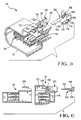
- FIGURE 1 is a rear perspective view of one embodiment of an electrical connector of the invention with a connector position assurance device exploded therefrom.
- FIGURE 2 is an enlarged perspective view of the connector position assurance device of Figure 1.
- FIGURE 3 is a front perspective view of the electrical connector shown in Figure 1 with the connector position assurance device provided in a fully inserted position.
- FIGURE 4 is a front perspective view of a second electrical connector with an position assurance device exploded therefrom.
- FIGURE 5 is a perspective cross-sectional view of the connector shown in Figure 4, with the connector position assurance device removed therefrom.
- FIGURE 6 is a cross-sectional view of the connector assembly prior to the mating of the first and second connectors and prior to the insertion of the Connector position assurance device therein.
- FIGURE 7 is a perspective cross-sectional view, similar to that of Figure 5, showing the connector position assurance device in a first position.
- FIGURE 8 is a cross-sectional view, similar to that of Figure 6, showing the connectors partially mated together and the connector position assurance device in the first position.
- FIGURE 9 is a perspective cross-sectional view, similar to that of Figure 7, showing the connector position assurance device in a second position.
- FIGURE 10 is a cross-sectional view, similar to that of Figure 8, showing the connectors mated together and the connector position assurance device in the second position.
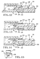
- FIGURE 11 is a cross-sectional view of another alternative connector position assurance device positioned in the first position and the connector not mated to a mating connector.
- FIGURE 12 is a cross-sectional view, similar to that of Figure 11, showing the movement of the connector position assurance device as the mating connector is mated to the connector.
- FIGURE 13 is a cross-sectional view, similar to that of Figure 12, showing the movement of the connector position assurance device as the mating of the mating connector to the connector continues.
- FIGURE 14 is a cross-sectional view, similar to that of Figure 13, showing the mating connector fully mated to the connector and the connector position assurance device fully inserted therein.
- FIGURE 15 is partial enlarged view of the connector position assurance device positioned in a slot on the electrical connector.
- Referring to Figures 1 and 3, a first
electrical connector 10 is shown. The particular connector shown has amating face 12 and awire receiving face 14. Contact receivingcavities 16 extend from proximate the mating face to proximate thewire receiving face 14. The contact receiving cavities are dimensioned to receive contacts (not shown) therein. It should be noted that the configuration of the housing may vary according to the application. - A connector position
assurance receiving area 20 is provided proximate a top surface of thefirst connector 10. Thereceiving area 20 has ashroud 22 provided proximate themating face 12. The shroud is dimensioned to receive a portion of a mating connector (not shown) therein. Thereceiving area 20 has opposedside walls wire receiving face 14. Each of the side walls has acavity 28 provided therein. The cavities extend from thewire receiving face 14 toward themating face 12, and are essentially parallel to the axis of thecontact receiving cavities 16. - Provided between the
side walls wire receiving face 14 is aprimary latch 30. As is best shown in Figure 3, theprimary latch 30 has two spaced apartresilient arms 32 which are joined at the free end thereof by a cross member (not shown). Intermediate the fixed ends and the free ends of theresilient arms 32 is anengagement member 36. - Extending inwardly from the
side walls wire receiving face 14 are plastic retention barbs (not shown). - Connector
position assurance device 50, as best shown in Figures 1 and 2, has aconnector locking arm 52, amain body portion 54, anengagement portion 56, latchingarms 58, andstabilization members 60. - In the embodiment shown in Figure 2, the
latching arms 58 are provided on each side of themain body portion 54 and are positioned such that the longitudinal axis of the arms are essentially parallel to the longitudinal axis of thelocking arm 52. The latching arms are spaced from the main body portion to allow thefree ends 62 thereof to be resiliently deformed. Eachlatching arm 54 has a firstangled surface 70 proximate thefree end 62, afirst locking shoulder 72, a secondangled surface 74 and asecond locking shoulder 76. -
Stabilization members 60 extend in a direction which is essentially perpendicular toconnector locking arm 52. Themembers 60 are cylindrical in configuration and have an enlargedfree end portion 78. The enlarged free end portion has a larger diameter than the remainder of the stabilization member. - Referring to figures 4 through 10, an alternative embodiment is shown. Although the first
electrical connector 110 is different thanconnector 10, the principals of the connector are essentially the same. Theparticular connector 110 has amating face 112 and awire receiving face 114. Contact receivingcavities 116 extend from proximate themating face 112 to proximate thewire receiving face 114. The contact receiving cavities are dimensioned to receive contacts (not shown) therein. - A connector position
assurance receiving area 120 is provided proximate a top surface of thefirst connector 110. The receivingarea 120 has ashroud 122 provided proximate themating face 112. The shroud is dimensioned to receive a portion of amating connector 118 therein. The receivingarea 120 has opposedside walls 124, 126 (Figure 4) which extend rearward proximate thewire receiving face 114. - Provided between the
side walls wire receiving face 114 is aprimary latch 130. As is best shown in Figure 4, theprimary latch 110 has two spaced apartresilient arms 132 which are joined at the free end thereof by across member 134. Intermediate the fixed ends and the free ends of theresilient arms 132 is anengagement member 136. - Extending inwardly from the
side walls wire receiving face 114 areplastic retention barbs 138. - Connector
position assurance device 150, as best shown in Figures 5 and 6, has aconnector locking arm 152, amain body portion 154, anengagement portion 156, and latchingarms 158. - The latching
arms 158 are provided on each side of themain body portion 154 and are positioned such that the longitudinal axis of the arms are essentially parallel to the longitudinal axis of thelocking arm 152. Referring to Figure 5, the latching arms are spaced from the main body portion to allow the free ends 162 thereof to be resiliently deformed. Each latchingarm 154 has a firstangled surface 170 proximate thefree end 162, afirst locking shoulder 172, a secondangled surface 174 and asecond locking shoulder 176. - The operation of the connector position assurance device is illustrated in Figures 5 through 10. Figures 5 and 6 show connector
position assurance devices 150 prior to insertion into the firstelectrical connector 110. - The
device 150 is inserted into theconnector 110 and is maintained in an initial position, as shown in Figure 7. As this insertion occurs, the firstangled surfaces 170 of the latchingarms 158 cooperate withbarbs 138 to cause the latching arms to deform resiliently inward. As the insertion continues, the latching arms continue to move relative to thebarbs 138, causing the first locking shoulders 172 to move beyond the barbs. As this occurs, thelatch arms 158 resiliently return to their unstressed position, thereby capturing thebarbs 138 between the first locking shoulders 172 and the secondangled surface 174. This defines the initial position. - As is shown in Figure 8, with the connector position assurance device in the initial position, the
mating connector 118 can be mated toconnector 110. As themating connector 118 is moved into engagement withconnector 110, alatch 180 ofconnector 118 cooperates withlatch 130 ofconnector 110. A connector latch receiving end oflatch 180 engages thecross member 134 oflatch 130. This engagement causes theprimary latch 130 to resiliently deform, as shown in Figure 8. The positioning of thedevice 150 in the first position aligns thedevice 150 with slots provided in theprimary latch 130, thereby allowing the resilient movement of the latch. - After the
mating connector 118 has been fully inserted into theconnector 110, with shoulders of thelatches device 150 is moved to the fully inserted or final position. As shown in Figures 9 and 10, in the fully inserted position, theconnector locking arm 152 is positioned under thecross member 134 oflatch 130. The lockingarm 152 is made of relatively thick plastic and therefore, does not have resilient characteristics. The lockingarm 152 is also supported by asupport member 168 ofconnector 110, to prevent thelocking arm 152 from deforming downward. Consequently, the positioning of the locking arm under the cross member prevents the resilient movement of thelatch 130 and ensures that theconnectors - It is worth noting that if
connectors device 150 to its final position. Consequently, if the connectors are not properly mated, thedevice 150 cannot be fully inserted, providing a visual indication that the mating is inadequate. - If the
connectors engagement portion 156 and pulls the contactposition assurance device 150 in a direction opposed to the direction of insertion. As this occurs, thebarbs 138 cause the latchingarms 158 to deform resiliently inward. The force required to move thedevice 150 from the final position to the initial position is determined by the angle of the second locking shoulder 176 (i.e. the steeper the slope of the shoulder, the more force required). The removal of thedevice 150 continues until the latching arms return to the unstressed position, causing the first locking shoulders 172 to engage thebarbs 138. As theshoulders 172 are essentially perpendicular to the longitudinal axis of the latching arms, the force required to remove the device beyond the initial position will damage the connector position assurance device. - The operation of the connector
position assurance device 50 shown in Figures 1 through 3 is essentially the same as that described above. However,device 50 hasstabilization members 60 which are positioned incavities 28, as shown in Figure 3. The enlargedfree end portions 78 are spaced apart a distance which is slightly greater than the distance betweenside walls enlarged end portions 78 withside walls connector assurance device 50 will be properly inserted, i.e. thedevice 50 will not be skewed or rotated as it is moved relative to theconnector 10. - Figures 11 through 15 disclose another embodiment of a connector
position assurance device 250. This embodiment has many of the same features asconnector 150 described above. The lockingarm 252 has ananti-overstress projection 290 which extends from proximate a free end thereof in a downward direction as viewed in Figures 11 through 14. As best shown in Figure 15, the width ofprojection 290 is less than the width of thelocking arm 252. - Referring to Figures 11 and 12, when the
locking arm 252 is in an unstressed position, the free end is offset in the direction from the fixed end. In the figures, the free end is upwardly offset from the fixed end. This offset can be accomplished in various ways including molding the locking arm in this "bent" configuration or bending the locking arm after molding to cause the locking arm to take a permanent set. - A
slot 294 is positioned in the receivingarea 220 of theconnector 210. The slot is dimensioned to be slightly larger thanprojection 290, as is shown in Figure 15. - As the connector
position assurance device 250 is inserted into theconnector 210, theanti-overstress projection 290 is positioned in theslot 294 and slides therein. The positioning of the projection in the slot provides a guide and centering means which ensures that the free end of thelocking arm 252 will be properly positioned in the receivingarea 220 of theconnector 210. As thelocking arm 252 is wider than theprojection 290 and theslot 294, surfaces of the locking arm cooperate with the support member 268 to adequately support the locking arm. - The connector
position assurance device 250 is maintained in the initial and final positions in the manner described above. However, thedevice 250 cannot be moved to the final position untilmating connector 218 is fully mated toconnector 210. As shown in Figure 11, if thedevice 250 is moved toward the final position before the mating connector is properly positioned, the offset free end of thelocking arm 252 will engage thecross member 234 of theprimary latch 230, thereby preventing the movement of thedevice 250 into the final position. - As the
mating connector 218 is inserted into theconnector 210, thelatch 280 of the mating connector cooperates with thelatch 230, as shown in Figure 12. A connector latch receiving end of thelatch 280 engages thecross member 234, causing theprimary latch 230 to resiliently pivot. The positioning of thedevice 250 in the first position aligns thedevice 250 with slots provided in theprimary latch 230 as the latch pivots. - As the insertion of the
mating connector 218 continues to the fully mated position, thelatch 280 moves past thecross member 234, thereby allowing theprimary latch 230 to return to its unstressed position. As this occurs, thelatch 280 engages the free end of thelocking arm 252 of thedevice 250. As the insertion continues, the lockingarm 252 is moved downward to the position shown in Figure 13. In this position, the latch has deformed thelocking arm 252. - With the
mating connector 218 fully inserted and the locking arm deformed, the connector position assurance device is moved to the final position. Thedevice 250 is able to move beyond thecross member 234 because thelatch 280 maintains the free end of thearm 252 in a position below thecross member 234. - In the final position shown in Figure 14, the removal of the mating connector from the connector is prevented unless the connector position assurance device has been moved to the initial position. In the final position, the
anti-overstress projection 290 will engage a top surface of the mating connector when a downward force is applied to the primary latch. As the height of the anti-overstress projection is approximately equal to the space provided between the latch and the top surface, the downward movement of thecross member 234 is essentially prevented, thereby preventing the removal of themating connector 218 from theconnector 210. Therefore, in order to remove themating connector 218, thedevice 250 is moved to the initial position, theprimary latch 230 is depressed, and the mating connector is removed. This prevents the unwanted removal of the mating connector due to harsh environments or operator error.
Claims (5)
- A connector position assurance device (150) for use with mating connectors, the connector position assurance device comprising:
a locking arm (152) which extends from a body portion (154), the locking arm being stiff and being dimensioned to cooperate with a respective portion of a first mating connector (118); and
at least one latching arm (158) which cooperates with the mating connectors to movably maintain the connector position assurance device (150) on a respective connector (110), at least one latching arm being movable between a first and a second position. - A connector position assurance device as recited in claim 1 wherein the locking arm (152) engages a section of the first connector (118) to prevent the movement of the connector position assurance device (150) from the first position to the second position unless the first mating connector (118) and a second mating connector (110) are properly mated together.
- A connector position assurance device as recited in claim 1 wherein the at least one latching arm (158) is spaced from the body portion (154) to allow a free end (162) thereof to be resiliently deformed.
- A connector position assurance device as recited in claim 3 wherein at least two latching arms are provided on the body portion (154), wherein the longitudinal axis of the latching arms (158) is essentially parallel to the longitudinal axis of the locking arm (152).
- A connector position assurance device as recited in claim 4 wherein each latching arm (158) has first angled surface (170) proximate the free end, a first locking shoulder (172), a second angled surface (174), and a second locking shoulder (176).
Applications Claiming Priority (2)
| Application Number | Priority Date | Filing Date | Title |
|---|---|---|---|
| US15934793A | 1993-11-30 | 1993-11-30 | |
| US159347 | 1993-11-30 |
Publications (2)
| Publication Number | Publication Date |
|---|---|
| EP0655807A2 true EP0655807A2 (en) | 1995-05-31 |
| EP0655807A3 EP0655807A3 (en) | 1995-12-13 |
Family
ID=22572193
Family Applications (1)
| Application Number | Title | Priority Date | Filing Date |
|---|---|---|---|
| EP94308098A Withdrawn EP0655807A3 (en) | 1993-11-30 | 1994-11-03 | Connector position assurance device. |
Country Status (7)
| Country | Link |
|---|---|
| EP (1) | EP0655807A3 (en) |
| JP (1) | JPH087982A (en) |
| KR (1) | KR950015865A (en) |
| CN (1) | CN1110016A (en) |
| AU (1) | AU7775594A (en) |
| BR (1) | BR9404767A (en) |
| TW (1) | TW252228B (en) |
Cited By (27)
| Publication number | Priority date | Publication date | Assignee | Title |
|---|---|---|---|---|
| EP0788193A2 (en) * | 1995-09-21 | 1997-08-06 | Yazaki Corporation | Electric connector |
| WO1997049146A1 (en) * | 1996-06-17 | 1997-12-24 | The Whitaker Corporation | Connector mating assurance device |
| DE19645717A1 (en) * | 1996-11-06 | 1998-05-07 | Framatome Connectors Int | Plug-in connector with primary and secondary locking devices |
| EP0848458A1 (en) * | 1996-12-13 | 1998-06-17 | Sumitomo Wiring Systems, Ltd. | Connector with engagement detection means |
| EP0848456A2 (en) * | 1996-12-13 | 1998-06-17 | General Motors Corporation | Electrical connector with locking connector position assurance member |
| EP0889557A2 (en) * | 1997-07-01 | 1999-01-07 | Sumitomo Wiring Systems, Ltd. | Snap-fit connector |
| EP0891014A2 (en) * | 1997-07-08 | 1999-01-13 | Yazaki Corporation | Lock-detecting Connector |
| EP1009066A2 (en) * | 1998-12-11 | 2000-06-14 | Whitaker Corporation | Connector-latching device |
| GB2368472A (en) * | 2000-09-22 | 2002-05-01 | Yazaki Corp | A connector with a lock ensuring mechanism |
| GB2368731A (en) * | 2000-09-22 | 2002-05-08 | Yazaki Corp | A connector with a lock ensuring mechanism |
| EP1235311A2 (en) * | 2001-02-09 | 2002-08-28 | Tyco Electronics Corporation | Electrical connector assembly with a laterally deflectable latch member and CPA |
| EP1271707A1 (en) * | 2001-06-26 | 2003-01-02 | Kia Motors Corporation | Wire-harness connector of electric apparatus |
| DE10146702B4 (en) * | 2000-09-22 | 2004-12-16 | Yazaki Corp. | Connector with a locking mechanism |
| EP1521338A1 (en) * | 2003-09-30 | 2005-04-06 | Exon Science Inc. | Cable connector assembly |
| DE10341136A1 (en) * | 2003-09-06 | 2005-04-07 | Hirschmann Austria Gmbh | Locking element for a plug connection |
| WO2006053717A1 (en) | 2004-11-16 | 2006-05-26 | Fci | Plug connector arrangement with secondary locking |
| DE102005019261A1 (en) * | 2005-04-26 | 2006-11-09 | Kostal Kontakt Systeme Gmbh | Electrical connector for motor vehicle, has two connector paths that comprise control edges meeting one another when connector parts are joined with one another, and latch led back while connecting two connector parts |
| WO2014198928A1 (en) * | 2013-06-14 | 2014-12-18 | Tyco Electronics Amp Gmbh | Plug and connector arrangement |
| US8926355B2 (en) | 2012-06-29 | 2015-01-06 | Lear Corporation | Connector position assurance device for a connector assembly |
| DE202015103898U1 (en) | 2015-07-24 | 2015-09-10 | Lisa Dräxlmaier GmbH | Locking an electrical connector |
| US9362676B2 (en) | 2014-09-04 | 2016-06-07 | Delphi Technologies Inc. | Connector with connector position assurance device |
| KR101746969B1 (en) | 2014-12-22 | 2017-06-14 | 스미토모 덴소 가부시키가이샤 | Connector |
| EP3211729A1 (en) * | 2016-02-25 | 2017-08-30 | Dai-Ichi Seiko Co., Ltd. | Electrical connector |
| KR101835115B1 (en) | 2015-09-16 | 2018-04-19 | 몰렉스 엘엘씨 | Connector assembly having cpa |
| DE202017101632U1 (en) * | 2017-03-21 | 2018-06-22 | Wago Verwaltungsgesellschaft Mbh | Plug arrangement and locking device for locking a mating connector to a connector |
| DE102017123696A1 (en) * | 2017-10-11 | 2019-04-11 | Amphenol-Tuchel Electronics Gmbh | High-current connector comprising a plug-in element and a socket element and a locking device |
| EP3703196A4 (en) * | 2017-10-23 | 2021-07-21 | Tyco Electronics Japan G.K. | Connector and connector assembly |
Families Citing this family (7)
| Publication number | Priority date | Publication date | Assignee | Title |
|---|---|---|---|---|
| JPH09219255A (en) * | 1996-02-07 | 1997-08-19 | Yazaki Corp | Double lock connector |
| JP2005293990A (en) * | 2004-03-31 | 2005-10-20 | Iriso Denshi Kogyo Kk | Connector |
| JP4723395B2 (en) * | 2006-02-14 | 2011-07-13 | 日本圧着端子製造株式会社 | Electrical connector, electrical connector assembly including the electrical connector, and lock release prevention member included therein |
| CN103967350B (en) * | 2014-05-12 | 2016-03-30 | 于浩 | A kind of plug-in type lock dog |
| JP6311573B2 (en) * | 2014-11-05 | 2018-04-18 | 住友電装株式会社 | connector |
| US10038278B2 (en) * | 2016-03-17 | 2018-07-31 | Te Connectivity Corporation | Electrical connector having a connector position assurance element |
| JP6839145B2 (en) * | 2018-09-03 | 2021-03-03 | 矢崎総業株式会社 | connector |
Citations (3)
| Publication number | Priority date | Publication date | Assignee | Title |
|---|---|---|---|---|
| US4634204A (en) * | 1985-12-24 | 1987-01-06 | General Motors Corporation | Electrical connector with connector position assurance/assist device |
| EP0449122A2 (en) * | 1990-03-23 | 1991-10-02 | Yazaki Corporation | Detector device for coupled connector |
| US5120255A (en) * | 1990-03-01 | 1992-06-09 | Yazaki Corporation | Complete locking confirming device for confirming the complete locking of an electric connector |
-
1994
- 1994-11-03 EP EP94308098A patent/EP0655807A3/en not_active Withdrawn
- 1994-11-07 TW TW083110257A patent/TW252228B/zh active
- 1994-11-10 AU AU77755/94A patent/AU7775594A/en not_active Abandoned
- 1994-11-18 KR KR1019940030384A patent/KR950015865A/en not_active Application Discontinuation
- 1994-11-28 BR BR9404767A patent/BR9404767A/en not_active IP Right Cessation
- 1994-11-30 JP JP6296246A patent/JPH087982A/en not_active Withdrawn
- 1994-11-30 CN CN94112889A patent/CN1110016A/en active Pending
Patent Citations (3)
| Publication number | Priority date | Publication date | Assignee | Title |
|---|---|---|---|---|
| US4634204A (en) * | 1985-12-24 | 1987-01-06 | General Motors Corporation | Electrical connector with connector position assurance/assist device |
| US5120255A (en) * | 1990-03-01 | 1992-06-09 | Yazaki Corporation | Complete locking confirming device for confirming the complete locking of an electric connector |
| EP0449122A2 (en) * | 1990-03-23 | 1991-10-02 | Yazaki Corporation | Detector device for coupled connector |
Cited By (50)
| Publication number | Priority date | Publication date | Assignee | Title |
|---|---|---|---|---|
| EP0788193A2 (en) * | 1995-09-21 | 1997-08-06 | Yazaki Corporation | Electric connector |
| EP0788193A3 (en) * | 1995-09-21 | 1997-10-15 | Yazaki Corp | Electric connector |
| US5879180A (en) * | 1995-09-21 | 1999-03-09 | Yazaki Corporation | Electric connector |
| WO1997049146A1 (en) * | 1996-06-17 | 1997-12-24 | The Whitaker Corporation | Connector mating assurance device |
| DE19645717A1 (en) * | 1996-11-06 | 1998-05-07 | Framatome Connectors Int | Plug-in connector with primary and secondary locking devices |
| DE19645717C2 (en) * | 1996-11-06 | 1998-08-27 | Framatome Connectors Int | Plug-in connection with secondary locking secured in the unplugged state against activation |
| EP0848456A2 (en) * | 1996-12-13 | 1998-06-17 | General Motors Corporation | Electrical connector with locking connector position assurance member |
| EP0848458A1 (en) * | 1996-12-13 | 1998-06-17 | Sumitomo Wiring Systems, Ltd. | Connector with engagement detection means |
| US5910028A (en) * | 1996-12-13 | 1999-06-08 | Sumitomo Wiring Systems, Ltd. | Connector |
| EP0848456A3 (en) * | 1996-12-13 | 1999-06-16 | General Motors Corporation | Electrical connector with locking connector position assurance member |
| EP0889557A2 (en) * | 1997-07-01 | 1999-01-07 | Sumitomo Wiring Systems, Ltd. | Snap-fit connector |
| EP0889557A3 (en) * | 1997-07-01 | 2000-01-19 | Sumitomo Wiring Systems, Ltd. | Snap-fit connector |
| US6126480A (en) * | 1997-07-01 | 2000-10-03 | Sumitomo Wiring Systems, Ltd. | Connector |
| EP0891014A2 (en) * | 1997-07-08 | 1999-01-13 | Yazaki Corporation | Lock-detecting Connector |
| US6109955A (en) * | 1997-07-08 | 2000-08-29 | Yazaki Corporation | Lock-detecting connector |
| EP0891014A3 (en) * | 1997-07-08 | 1999-11-03 | Yazaki Corporation | Lock-detecting Connector |
| EP1009066A2 (en) * | 1998-12-11 | 2000-06-14 | Whitaker Corporation | Connector-latching device |
| EP1009066A3 (en) * | 1998-12-11 | 2000-10-11 | Whitaker Corporation | Connector-latching device |
| US6582243B2 (en) | 2000-09-22 | 2003-06-24 | Yazaki Corporation | Connector provided with lock ensuring mechanism |
| DE10164856B4 (en) * | 2000-09-22 | 2008-08-07 | Yazaki Corp. | Connector with a locking mechanism |
| GB2368731A (en) * | 2000-09-22 | 2002-05-08 | Yazaki Corp | A connector with a lock ensuring mechanism |
| US6461186B1 (en) | 2000-09-22 | 2002-10-08 | Yazaki Corporation | Connector with lock ensuring mechanism |
| DE10146702B4 (en) * | 2000-09-22 | 2004-12-16 | Yazaki Corp. | Connector with a locking mechanism |
| GB2368472B (en) * | 2000-09-22 | 2003-04-09 | Yazaki Corp | Connector provided with lock ensuring mechanism |
| GB2368472A (en) * | 2000-09-22 | 2002-05-01 | Yazaki Corp | A connector with a lock ensuring mechanism |
| GB2368731B (en) * | 2000-09-22 | 2004-05-26 | Yazaki Corp | Connector with lock ensuring mechanism |
| EP1235311A2 (en) * | 2001-02-09 | 2002-08-28 | Tyco Electronics Corporation | Electrical connector assembly with a laterally deflectable latch member and CPA |
| EP1235311A3 (en) * | 2001-02-09 | 2004-06-02 | Tyco Electronics Corporation | Electrical connector assembly with a laterally deflectable latch member and CPA |
| EP1271707A1 (en) * | 2001-06-26 | 2003-01-02 | Kia Motors Corporation | Wire-harness connector of electric apparatus |
| KR100419728B1 (en) * | 2001-06-26 | 2004-02-21 | 기아자동차주식회사 | Thd Wire-harnes Connector of Electronic Apparatus |
| DE10341136A1 (en) * | 2003-09-06 | 2005-04-07 | Hirschmann Austria Gmbh | Locking element for a plug connection |
| EP1521338A1 (en) * | 2003-09-30 | 2005-04-06 | Exon Science Inc. | Cable connector assembly |
| US7766685B2 (en) | 2004-11-16 | 2010-08-03 | Fci | Plug connector arrangement with secondary locking |
| CN101076925B (en) * | 2004-11-16 | 2010-05-05 | Fci公司 | Plug connector arrangement with secondary locking |
| WO2006053717A1 (en) | 2004-11-16 | 2006-05-26 | Fci | Plug connector arrangement with secondary locking |
| DE102005019261A1 (en) * | 2005-04-26 | 2006-11-09 | Kostal Kontakt Systeme Gmbh | Electrical connector for motor vehicle, has two connector paths that comprise control edges meeting one another when connector parts are joined with one another, and latch led back while connecting two connector parts |
| US8926355B2 (en) | 2012-06-29 | 2015-01-06 | Lear Corporation | Connector position assurance device for a connector assembly |
| WO2014198928A1 (en) * | 2013-06-14 | 2014-12-18 | Tyco Electronics Amp Gmbh | Plug and connector arrangement |
| US9362676B2 (en) | 2014-09-04 | 2016-06-07 | Delphi Technologies Inc. | Connector with connector position assurance device |
| KR101746969B1 (en) | 2014-12-22 | 2017-06-14 | 스미토모 덴소 가부시키가이샤 | Connector |
| DE202015103898U1 (en) | 2015-07-24 | 2015-09-10 | Lisa Dräxlmaier GmbH | Locking an electrical connector |
| KR101835115B1 (en) | 2015-09-16 | 2018-04-19 | 몰렉스 엘엘씨 | Connector assembly having cpa |
| EP3211729A1 (en) * | 2016-02-25 | 2017-08-30 | Dai-Ichi Seiko Co., Ltd. | Electrical connector |
| US20170250492A1 (en) * | 2016-02-25 | 2017-08-31 | Dai-Ichi Seiko Co., Ltd. | Connector |
| US10014620B2 (en) * | 2016-02-25 | 2018-07-03 | Dai-Ichi Seiko Co., Ltd. | Downsizing of a connector having a connector position assurance function |
| DE202017101632U1 (en) * | 2017-03-21 | 2018-06-22 | Wago Verwaltungsgesellschaft Mbh | Plug arrangement and locking device for locking a mating connector to a connector |
| DE102017123696A1 (en) * | 2017-10-11 | 2019-04-11 | Amphenol-Tuchel Electronics Gmbh | High-current connector comprising a plug-in element and a socket element and a locking device |
| DE102017123696B4 (en) | 2017-10-11 | 2024-05-23 | Amphenol-Tuchel Electronics Gmbh | Connector comprising a plug element and a socket element and a locking device |
| EP3703196A4 (en) * | 2017-10-23 | 2021-07-21 | Tyco Electronics Japan G.K. | Connector and connector assembly |
| US11245228B2 (en) | 2017-10-23 | 2022-02-08 | Tyco Electronics Japan G.K. | Connector and connector assembly having a connector position assurance device |
Also Published As
| Publication number | Publication date |
|---|---|
| KR950015865A (en) | 1995-06-17 |
| EP0655807A3 (en) | 1995-12-13 |
| JPH087982A (en) | 1996-01-12 |
| AU7775594A (en) | 1995-06-08 |
| CN1110016A (en) | 1995-10-11 |
| BR9404767A (en) | 1995-07-25 |
| TW252228B (en) | 1995-07-21 |
Similar Documents
| Publication | Publication Date | Title |
|---|---|---|
| EP0655807A2 (en) | Connector position assurance device | |
| EP0804821B1 (en) | Housing latch with connector position assurance device | |
| EP1054481B1 (en) | A connector | |
| US5681178A (en) | Electrical connector with connector position assurance device | |
| US6244880B1 (en) | Low-insertion force connector | |
| US5944547A (en) | Connector shorting bar retention | |
| US6386898B1 (en) | Connector fitting construction | |
| EP0774801A2 (en) | Electrical terminal with protected locking lance and a connector therefor | |
| EP0726617A2 (en) | Connector with secondary locking and coupling mechanism | |
| WO2019180562A1 (en) | Connector position assurance member | |
| EP0993077A2 (en) | Half-fitting prevention connector and method of producing same | |
| EP3769377B1 (en) | Connector position assurance member | |
| JPH05275135A (en) | Female type electric terminal | |
| EP0954061B1 (en) | A connector | |
| EP1548894B1 (en) | A connector | |
| US5651704A (en) | Electrical connector with terminal retainer | |
| EP0573931B1 (en) | Lockable electrical connector assembly | |
| EP1091452A1 (en) | Electrical connector with exposed molded latches | |
| US10587076B2 (en) | Connector position assurance member | |
| US5928014A (en) | Electrical connector having a pair of connector housings | |
| CN111146651B (en) | Electrical connector having connector position assurance member for hood latch | |
| US6488547B2 (en) | Connector with longitudinally spaced locks for retaining terminal fittings | |
| CN113557641B (en) | Connector position assurance member | |
| JP2880253B2 (en) | Electrical connector | |
| EP2573881A1 (en) | Improved connector assembly having low coupling force retractable stabilizer |
Legal Events
| Date | Code | Title | Description |
|---|---|---|---|
| PUAI | Public reference made under article 153(3) epc to a published international application that has entered the european phase |
Free format text: ORIGINAL CODE: 0009012 |
|
| AK | Designated contracting states |
Kind code of ref document: A2 Designated state(s): DE FR GB IT |
|
| PUAL | Search report despatched |
Free format text: ORIGINAL CODE: 0009013 |
|
| AK | Designated contracting states |
Kind code of ref document: A3 Designated state(s): DE FR GB IT |
|
| 17P | Request for examination filed |
Effective date: 19960607 |
|
| 17Q | First examination report despatched |
Effective date: 19970624 |
|
| STAA | Information on the status of an ep patent application or granted ep patent |
Free format text: STATUS: THE APPLICATION IS DEEMED TO BE WITHDRAWN |
|
| 18D | Application deemed to be withdrawn |
Effective date: 19981019 |