EP3211653A1 - Elektromagnetisches relais für drei schaltpositionen - Google Patents
Elektromagnetisches relais für drei schaltpositionen Download PDFInfo
- Publication number
- EP3211653A1 EP3211653A1 EP16398001.4A EP16398001A EP3211653A1 EP 3211653 A1 EP3211653 A1 EP 3211653A1 EP 16398001 A EP16398001 A EP 16398001A EP 3211653 A1 EP3211653 A1 EP 3211653A1
- Authority
- EP
- European Patent Office
- Prior art keywords
- spring
- relay according
- relay
- armatures
- springs
- Prior art date
- Legal status (The legal status is an assumption and is not a legal conclusion. Google has not performed a legal analysis and makes no representation as to the accuracy of the status listed.)
- Granted
Links
- 230000002441 reversible effect Effects 0.000 claims abstract description 11
- 239000002184 metal Substances 0.000 claims description 15
- 229910052751 metal Inorganic materials 0.000 claims description 15
- 230000000284 resting effect Effects 0.000 claims description 13
- RYGMFSIKBFXOCR-UHFFFAOYSA-N Copper Chemical compound [Cu] RYGMFSIKBFXOCR-UHFFFAOYSA-N 0.000 claims description 6
- 229910052802 copper Inorganic materials 0.000 claims description 6
- 239000010949 copper Substances 0.000 claims description 6
- 230000004907 flux Effects 0.000 description 18
- 230000008901 benefit Effects 0.000 description 17
- 238000013459 approach Methods 0.000 description 14
- 238000004804 winding Methods 0.000 description 13
- 230000010287 polarization Effects 0.000 description 9
- 230000002829 reductive effect Effects 0.000 description 7
- 238000011161 development Methods 0.000 description 6
- XEEYBQQBJWHFJM-UHFFFAOYSA-N Iron Chemical group [Fe] XEEYBQQBJWHFJM-UHFFFAOYSA-N 0.000 description 5
- 238000000034 method Methods 0.000 description 5
- 230000007935 neutral effect Effects 0.000 description 5
- 238000013461 design Methods 0.000 description 4
- 230000008569 process Effects 0.000 description 4
- 230000007423 decrease Effects 0.000 description 3
- 230000000694 effects Effects 0.000 description 3
- 229910000881 Cu alloy Inorganic materials 0.000 description 2
- 238000005452 bending Methods 0.000 description 2
- 230000008878 coupling Effects 0.000 description 2
- 238000010168 coupling process Methods 0.000 description 2
- 238000005859 coupling reaction Methods 0.000 description 2
- 230000003247 decreasing effect Effects 0.000 description 2
- 230000001419 dependent effect Effects 0.000 description 2
- 230000005415 magnetization Effects 0.000 description 2
- 238000004519 manufacturing process Methods 0.000 description 2
- 230000009467 reduction Effects 0.000 description 2
- 230000004913 activation Effects 0.000 description 1
- 238000004026 adhesive bonding Methods 0.000 description 1
- 238000010276 construction Methods 0.000 description 1
- 238000006073 displacement reaction Methods 0.000 description 1
- 230000002349 favourable effect Effects 0.000 description 1
- 239000012467 final product Substances 0.000 description 1
- 229910052742 iron Inorganic materials 0.000 description 1
- 238000005304 joining Methods 0.000 description 1
- 239000000463 material Substances 0.000 description 1
- 230000002040 relaxant effect Effects 0.000 description 1
- 230000035939 shock Effects 0.000 description 1
- 238000004088 simulation Methods 0.000 description 1
- 239000007787 solid Substances 0.000 description 1
- 238000005728 strengthening Methods 0.000 description 1
- 238000012360 testing method Methods 0.000 description 1
- 230000003313 weakening effect Effects 0.000 description 1
Images


Classifications
-
- H—ELECTRICITY
- H01—ELECTRIC ELEMENTS
- H01H—ELECTRIC SWITCHES; RELAYS; SELECTORS; EMERGENCY PROTECTIVE DEVICES
- H01H50/00—Details of electromagnetic relays
- H01H50/64—Driving arrangements between movable part of magnetic circuit and contact
- H01H50/641—Driving arrangements between movable part of magnetic circuit and contact intermediate part performing a rectilinear movement
- H01H50/642—Driving arrangements between movable part of magnetic circuit and contact intermediate part performing a rectilinear movement intermediate part being generally a slide plate, e.g. a card
-
- H—ELECTRICITY
- H01—ELECTRIC ELEMENTS
- H01H—ELECTRIC SWITCHES; RELAYS; SELECTORS; EMERGENCY PROTECTIVE DEVICES
- H01H51/00—Electromagnetic relays
- H01H51/005—Inversing contactors
-
- H—ELECTRICITY
- H01—ELECTRIC ELEMENTS
- H01H—ELECTRIC SWITCHES; RELAYS; SELECTORS; EMERGENCY PROTECTIVE DEVICES
- H01H51/00—Electromagnetic relays
- H01H51/22—Polarised relays
- H01H51/2272—Polarised relays comprising rockable armature, rocking movement around central axis parallel to the main plane of the armature
- H01H51/2281—Contacts rigidly combined with armature
-
- H—ELECTRICITY
- H01—ELECTRIC ELEMENTS
- H01H—ELECTRIC SWITCHES; RELAYS; SELECTORS; EMERGENCY PROTECTIVE DEVICES
- H01H51/00—Electromagnetic relays
- H01H51/22—Polarised relays
- H01H51/26—Polarised relays with intermediate neutral position of rest
Definitions
- the present invention relates to an electromagnetic relay for motor reverse applications which has one coil to control two armatures for switching two spring arrangements coupled by a slider in to three switching positions, i.e. a center position defined as neutral or resting position corresponding to a motor brake or motor blocked situation, a right position defined as the coil being energized in a certain polarity corresponding to the application motor rotating clockwise, and a left slider position for an inversely polarized coil corresponding to the motor application rotating counter clockwise.
- Most of the currently available automotive relay designs for motor reverse involve a double relay solution in one housing with a standard armature rotation around a frame hinge, contact motion is circular and directly coupled to the armature through an electrical conducting metal spring element.
- Both relays are controlled by individual drivers, which transform a digital signal into a power signal that will activate the relay.
- the motor When one of the relays is being activated, the motor will rotate in a certain direction. By reversing the polarity of the motor, its angular motion can be reversed.
- the event in which both relays are activated at the same time has no practical function (both motor terminals connected to the positive potential).
- theoretically only three states are necessary, whereas four states are available. If the system can be reduced down to the only required three states, it can be controlled by one magnetic system only. Additionally the total number of required components may be reduced, and consequently the size of the system and assembly costs decreased as requested by the increased complexity of transportation solutions.
- the system which is disclosed in this case, has one relay with two magnetic systems, which share a frame, an armature, and NO terminal.
- the relay has two coils each having a winding and a core, which can be driven separately. The two coils are displaced on a base body.
- the relay has a common negative terminal, a single yoke and a single armature.
- This system due to the use of two coils and a spring arrangement being placed in the center, still requires more volume (two coil windings) enclosing the armature, and an increased assembly complexity when achieving smaller form factors since the armature and spring are placed in-between motors.
- the JPH06283088A discloses a small sized three states relay. Two electrical contacts, decoupled from each other, can be opened and closed with a single coil and two magnetic armatures.
- the two magnetic armatures anchored with the contacts are freely rotatable around supporting points and will move only in inwards direction from the resting position to the pole when the coil is energized. Only one armature is supposed to move to the pole when the coil is energized the other armature will stay in place.
- the disadvantage of this approach is the lack of an easy electrical decoupling solution between the two changeover systems that may require more volume, the difficulty in maintaining contact force on the armature, which is supposed to stay in place when the coil is energized since both armatures are attracted inwards although at different intensities.
- the relay can be built at low cost.
- This electromagnetic relay has only three possible configurations instead of four, with a stable central neutral position and two additional positions controlled by one magnetic coil.
- Such relay can be used for motor reverse relays applications, where the main advantage is to have a smaller printable circuit board profile size, reduced weigh, less connections and lower cost.
- least one magnet of the magnetic system is a three poles system.
- the magnetic system of the relay is one coil winding around a core with a magnet on the base having three poles centered between two armatures.
- the advantage of using a single three poles magnet is the manufacturing simplicity since we use one bigger magnet instead of two small ones or two winded coils, coil bodies and cores.
- An additional advantage is that such system can be produced at low cost.
- Another advantage is that this approach will function with a relatively weak magnet.
- the magnetic system comprises two inversely polarized magnets having the core in the middle.
- the core is centered relatively to the magnet. This assures a symmetric polarization.
- the magnets have a North South North or South North South polarization; in this case the magnetic polarization intensity is not symmetric.
- This approach combined with the coupled mechanical system makes possible to use stronger magnets to reduce coil windings meanwhile maintaining contact forces and resilience to mechanical vibration something not possible in standard approaches like latching relays or other mono-stable non mechanically coupled systems.
- the electromagnetic relay described in this invention has one motor only instead of two. It needs only one signal source (driver), uses fewer parts (no second coil winding), has less complex shaped parts for the performance required by the application and can be reduced in size and weight compared to today's state of the art.
- the coil body and winding pay a relevant role in the final relay cost, due to copper consumption and size.
- the single location coil-winding relay covered by this invention can be built at a very low cost and size.
- the iron core can have a circular or rectangular section. Having a circular section provides better magnetic flux efficiency but may be harder to create T-Shape geometry (core/pole) in a single part.
- the rectangular shape main advantage is that it makes possible to stamp a relatively square profile in a single part.
- the core can have a T shape formed by joining two parts or by one single part. The bottom faces of the core are connected to a magnet if a three-pole magnet is used or if not, each magnet is placed adjacent to a center iron part.
- the coil can be single or double but winded in the same coil body; this will be dependent on the application.
- the motor is placed centered within two armatures on each side.
- the magnetic system purpose is to generate an attractive force on the rotating armature located in front of the pole.
- the magnetic force is obtained by the resultant of a magnetic field generated by a magnet and the energizing of a coil.
- the magnets purpose is to create a force imbalance on the two armatures defining in which direction the coupled system will move (left or right). Position and polarization of the magnets affect the behavior of the magnetic system.
- the magnets have to be placed in a way to affect the two branches of the magnetic system, i.e. either centered in regards to the core, but in this case a three pole magnet would be more favorable, or positioned anywhere on the magnetic flux path in one of the two branches.
- the three pole magnet is asymmetric in polarization and is placed centered to the core, generating different flux intensities in each flux path which in turn generates a flux differential when pulling the armatures to the center pole (one branch will have stronger pull forces).
- the flux differential associated to the energizing of the coil in normal or reversed polarity generates in each case a stronger magnetic pull on one of the sides; the use of a three-pole magnet reduces the number of components and respective cost of the final product.
- the use of two core enclosing magnets with reverse magnetization (North - South with North - South i.e.) provides the same function but with the advantage that stronger magnets can be used, which can help reducing the number of coil windings but adds part count.
- the two armatures can only rotate towards the central pole due to magnetic influence. However since both armatures are coupled by the card and as the magnetic field attraction is higher with approximation to the pole for each activation they will rotate in respect to a rotation hinge at a certain angle in clockwise or counter clockwise direction so to reach the rotate right or rotate left states. Consequently, one armature will move towards the pole and the other will move away from it.
- the armatures rotate around the base or, a magnet edge or an iron edge.
- the armatures can vary in dimensions, i.e. height and width and thickness.
- the armatures are coupled to the non-conductive card each by a metal connection. Coupling will ensure having a stable system.
- the card, in particular the non-conductive card, will move left or right, giving rise to a hybrid rotational/translational motion system.
- the advantage of using a metal is that it is easier to process.
- connections may have different shapes, including for example L shape, or U shape.
- L shape The L shaped connection between armature and card reduce the degrees of freedom of motion between parts.
- U shape connection between two armatures and the card reduce degrees of freedom and number of parts used. Both U and L shape parts can be over molded into the card.
- the armatures are in direct contact with the non-conductive card, which will improve the manufacturing process and reduce system complexity further.
- the function of the card is to connect mechanically the two springs and magnetic systems on both sides of the coil body.
- the two systems have to be electrically isolated for the relay to function and prevent short-circuit.
- the armatures can be shaped in such way to be thinner at the top and at the bottom faces, and around at the rotation hinge.
- the non-conductive card can be rigid or flexible.
- the advantage of being flexible is that this helps to reduce the overall stiffness of the armature card connection especially when using an L shape metal connection.
- the advantage of being rigid is that it is easier to produce in the case of direct contact between armature and card.
- the central spring of each spring arrangement is in contact with one terminal spring on one side in a normally closed configuration and is simultaneously not in contact with the other terminal spring on the other side in a normally open configuration.
- the central spring of each spring arrangement is a spring which can contact two terminals, called change-over (CO) spring.
- CO change-over
- the CO spring of each springs arrangement is in contact with one terminal spring on one side in a normally closed (NC) configuration or NC terminal and is simultaneously not in contact with the other terminal spring on the other side in a normally open (NO) configuration or NO terminal, all terminals have a contact element attached to it.
- NC normally closed
- NO normally open
- the four required NO and NC terminal springs can be reduced to one single copper strip part which is afterwards over-molded in plastic and bended in position afterwards.
- the two central springs are connected to the non-conductive card.
- the non-conductive card or slider or translational card bridging the two central springs has the function to couple together the motion of the CO springs and the motion of the armatures.
- the card is placed above the base part and the motor in between the CO springs.
- the spring arrangements makes simultaneous movement in the left or right direction coupled to the armatures movement. Both armatures rotate simultaneously in the same direction but one armature will have a strong magnetic pull towards the pole face. The motion direction of the card is given by the armature which has the strongest magnetic attraction force.
- the advantage of this approach is to obtain three stable states out of one magnetic coil system.
- each spring arrangement includes one or more stopper element to keep the contact spring in a pre-tensioned rest position.
- the stopper elements or base stoppers can be of three different types. The first stopper element is located near the two NO spring terminals and the second stopper is located near the NC spring terminal. Both stoppers have the function to prevent the spring terminals from moving inwards towards the CO spring.
- the base stoppers are made from plastic or metal. Stoppers can either be a protrusion from the base part or independent elements built from other parts. The advantage of using plastic has to do with the easy processability, i.e. when the stopper is a protrusion of the base part, it is made out of a unitary injected part, without involvement of additional assembly process steps. Metal stoppers have increased strengths resistance.
- the advantage of using independent parts is that not only the base but also the cover can be used as stoppers as well.
- the third type of base stopper in located near the two CO springs. This type of stopper has the effect of pre-tensioning the spring in one direction. This type of stopper is a protrusion from the base part that bends outwards gaining a pretension when the CO spring is stitched in the base part.
- Over-travel is defined by the displacement of the NO contact after the CO contact reaches it. Is the additional travel done from the CO spring to bring the NO contact out of the centered position.
- the two NC terminals can be set to be pre-tensioned against the CO spring to ensure vibration resistance. Pre-tension of CO contact to NC contact is obtained by their positioning and overall difference of stiffness between both CO springs versus both NC terminals. Terminals and spring have cuts on their surface in the bending area to help increase or decrease spring stiffness for adjusting relay performance and to improve fatigue resistance. Terminals can be flexible or stiff. In an alternative embodiment, pretension can also be reached with an S form element formed by a bending in the terminal itself.
- the left and right normally open terminals are connected together with a single output terminal and are stamped from a single metal strip and/or the left and right normally closed terminals are connected together with a different single output terminal, stamped from a single metal strip.
- This configuration allows having overtravel in a three state relay.
- all terminal springs normally open and normally closed can be produced in and from one single copper strip.
- Working with a single copper strip allows reducing the complexity of the process by producing four flexible terminals with a single stamping tool out of a single strip.
- a spring profile is stamped.
- the base is over-molded into the metal strip profile.
- the terminals are then folded of 90 degrees. All the parts are formed from a single stamping press. Therefore, no gluing process is needed to fix the terminals into the base.
- two metal springs are pressed against the base and glued to it.
- standard available processes employ two stamping tools producing each two terminals which are then glued on a plastic base. Additionally two springs have to be produced with a stamping tool.
- the electromagnetic relay described in this invention shows significant reduction of size, i.e. up to 30% smaller than the smallest TE automotive relay, due to the fact that the volume occupied by one of two windings is omitted reducing the overall size and PCB surface area. Since one coil winding only is being used, frame size, core, coil body and copper windings usage are reduced allowing reducing weight, part count and cost.
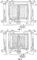
- the relay 1 comprises a magnetic system consisting of a three pole single magnet 100 located at the base of the system.
- the core 110 is located in the middle, between the two armatures 115.
- the single coil 105 is winded around the coil body.
- the iron core in Fig.1 has a T-shape.
- the coil has to be energized, generating an asymmetric magnetic field that attracts mainly one of the armatures to the pole.
- the relay is shown in the alternative configuration with two magnets 165 or 175 which are located at the base of the system and can be inversely polarized, North South with South North (165) or not, North South with North South (175).
- the core is located in the center in respect to the two magnets.
- the armatures will rotate around a fixed axis, giving rise to a hybrid rotational/translational motion of the card 150 towards the right side as can be seen in Fig. 4 or the left side, as in Fig. 5 .
- the armatures are connected to the card 150 by mean of connections 155, which can be metallic connections, plastic connections, flexible or rigid. The connections can be built with different shapes.
- the card is then further connected to the spring arrangements 120.
- the central spring or CO spring 125 of the arrangement is in contact with the card.
- the central spring is located within the two terminal springs 130 and 135.
- Fig. 1 shows the relay in the resting position. When the relay is in a resting position, the CO spring is in contact with the terminal spring 130, to establish a NC configuration or connection, while the other terminal 135 is in a NO configuration.
- the elements 140 and 145 are stopper elements, or base stoppers, which help to prevent terminals from bouncing back at the CO spring.
- Element 140 and 145 act as a stopper preventing terminal springs from moving towards the CO spring.
- a further detail of a stopper element is shown in Fig 8 .
- the element 147 is a plastic element located at the base of the CO spring that increases global spring stiffness, therefore helping maintaining the CO in a central position.
- the element 147 is protruding from the base and acts as support when the CO spring is in a pre-tensioned state.
- the dimension and shape of the element 147 can be modified in dependence of the desired overall system stiffness.
- Fig. 4 The situation in which the card moves to the right is illustrated in Fig. 4 .
- the coil When the coil is energized, a magnetic field is generated adding up to the magnetic field generated by the magnets in the magnetic loop.
- Coil operation polarity affects the flux direction added to the magnet generated flux, when using a three pole approach the magnet polarization intensity has to be different on each side of the flux path to generate an offset in force between the two armatures.
- Using a different approach with two magnets and aligned polarity North to South aligned with North to South means asymmetric
- the over-travel zone situation is reached, meaning that the armature on the left still has a certain travel until a full contact to the core/pole part is established.
- the stiffness of the over-travel zone is generated by the NO spring terminal design; the travel will end by contact to a fixed plastic stopper.
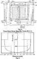
- Fig. 4 shows the three pole magnet configuration and the related generated magnetic flux path.
- the magnetic flux generated by the coil polarization is stronger on the left side and as result the force will be stronger in the path aligned with the generated flux.
- the armatures on the opposite side will have a weaker magnetic force since the corresponding flux is less intense due to the increased distance, thus moving the card sideways, opening more on one side the magnetic circuit and closing it on the other. Both armatures will have a residual attraction to the pole, but as they are connected together by the card the system will remain stable due to the stiffness of the mechanical spring elements.
- the magnetic flux behavior has been also verified by magnetic simulation.
- Fig 6 is the graph representing the force vs distance curves.
- the initial distance between the armatures and the core corresponds to a neutral position.
- the distance between the right armature and the core decreases, the distance between the left armature and the core increases.
- To a decrease of distance between armature and core on the right side corresponds an increase of the magnetic force acting on the right armature.
- the magnetic force on the right side will reach the highest values, on the left side there will be a residual magnetization.
- Fig. 7 shows two NO terminal springs (135), two NC terminals springs (130) and two CO terminal springs (125).
- the two NO and NC terminal springs are formed by a single copper alloy sheet. The shape is stamped, and afterwards over molded in plastic to make the base part in an un-bended state. Afterwards the contacts are soldered to the terminals and finally the terminals are bended towards their final shape.
- the main advantages of this approach are that we don't have to assembly several individual parts independently, the copper alloy strip is optimized since we don't need to cut off material to extract four spring terminals out of the sheet and handle them and it is possible to obtain a single solid part instead of having four very small loose parts.
- the two NO terminals are connected together and the two NC terminals are also connected together. The advantage of this is that we use only one output connection for each pair (NO and NC).
- Coil energizing was performed with a standard voltage drop of 12V. After proving the functionality of the concept in general, the design work was initiated to fit everything into a smaller, marketable size. The resulting design is about 30% smaller then smallest motor reverse relay available in the market and has considerably less components as it is using one magnetic system only instead of two.
Landscapes
- Physics & Mathematics (AREA)
- Electromagnetism (AREA)
- Electromagnets (AREA)
Priority Applications (1)
| Application Number | Priority Date | Filing Date | Title |
|---|---|---|---|
| EP16398001.4A EP3211653B1 (de) | 2016-02-23 | 2016-02-23 | Elektromagnetisches relais für drei schaltpositionen |
Applications Claiming Priority (1)
| Application Number | Priority Date | Filing Date | Title |
|---|---|---|---|
| EP16398001.4A EP3211653B1 (de) | 2016-02-23 | 2016-02-23 | Elektromagnetisches relais für drei schaltpositionen |
Publications (2)
| Publication Number | Publication Date |
|---|---|
| EP3211653A1 true EP3211653A1 (de) | 2017-08-30 |
| EP3211653B1 EP3211653B1 (de) | 2019-08-14 |
Family
ID=55484941
Family Applications (1)
| Application Number | Title | Priority Date | Filing Date |
|---|---|---|---|
| EP16398001.4A Active EP3211653B1 (de) | 2016-02-23 | 2016-02-23 | Elektromagnetisches relais für drei schaltpositionen |
Country Status (1)
| Country | Link |
|---|---|
| EP (1) | EP3211653B1 (de) |
Cited By (1)
| Publication number | Priority date | Publication date | Assignee | Title |
|---|---|---|---|---|
| EP3678158A1 (de) * | 2019-01-04 | 2020-07-08 | Tyco Electronics Componentes Electromecanicos Lda | Magnetischer antrieb und elektromagnetisches relais |
Citations (8)
| Publication number | Priority date | Publication date | Assignee | Title |
|---|---|---|---|---|
| DE924873C (de) * | 1952-04-20 | 1955-03-10 | Zahnradfabrik Friedrichshafen | Schaltanlage fuer einen umsteuerbaren Elektromotor, insbesondere zur Verwendung in Kraftfahrzeugen |
| US4609899A (en) * | 1984-07-20 | 1986-09-02 | La Telemecanique Electrique | Polarized electromagnet having three states and a control circuit for said electromagnet |
| JPH06283088A (ja) * | 1993-03-26 | 1994-10-07 | Matsushita Electric Works Ltd | 電磁継電器 |
| US5382934A (en) | 1991-07-09 | 1995-01-17 | Siemens Aktiengesellschaft | Electromagnetic changeover relay |
| JPH09102258A (ja) * | 1995-10-05 | 1997-04-15 | Saitama Nippon Denki Kk | リレー |
| EP0950253A1 (de) * | 1997-01-06 | 1999-10-20 | Siemens Electromechanical Components, Inc. | Polarisiertes relais mit festhaltvooichtung für den permanenten magnet |
| DE19957805A1 (de) * | 1999-12-01 | 2001-06-28 | Tyco Electronics Logistics Ag | Elektrische Umschaltvorrichtung |
| US20110272258A1 (en) * | 2010-05-04 | 2011-11-10 | Tyco Electronics Corporation | Switching devices configured to control magnetic fields to maintain an electrical connection |
-
2016
- 2016-02-23 EP EP16398001.4A patent/EP3211653B1/de active Active
Patent Citations (8)
| Publication number | Priority date | Publication date | Assignee | Title |
|---|---|---|---|---|
| DE924873C (de) * | 1952-04-20 | 1955-03-10 | Zahnradfabrik Friedrichshafen | Schaltanlage fuer einen umsteuerbaren Elektromotor, insbesondere zur Verwendung in Kraftfahrzeugen |
| US4609899A (en) * | 1984-07-20 | 1986-09-02 | La Telemecanique Electrique | Polarized electromagnet having three states and a control circuit for said electromagnet |
| US5382934A (en) | 1991-07-09 | 1995-01-17 | Siemens Aktiengesellschaft | Electromagnetic changeover relay |
| JPH06283088A (ja) * | 1993-03-26 | 1994-10-07 | Matsushita Electric Works Ltd | 電磁継電器 |
| JPH09102258A (ja) * | 1995-10-05 | 1997-04-15 | Saitama Nippon Denki Kk | リレー |
| EP0950253A1 (de) * | 1997-01-06 | 1999-10-20 | Siemens Electromechanical Components, Inc. | Polarisiertes relais mit festhaltvooichtung für den permanenten magnet |
| DE19957805A1 (de) * | 1999-12-01 | 2001-06-28 | Tyco Electronics Logistics Ag | Elektrische Umschaltvorrichtung |
| US20110272258A1 (en) * | 2010-05-04 | 2011-11-10 | Tyco Electronics Corporation | Switching devices configured to control magnetic fields to maintain an electrical connection |
Cited By (2)
| Publication number | Priority date | Publication date | Assignee | Title |
|---|---|---|---|---|
| EP3678158A1 (de) * | 2019-01-04 | 2020-07-08 | Tyco Electronics Componentes Electromecanicos Lda | Magnetischer antrieb und elektromagnetisches relais |
| EP3678159A1 (de) * | 2019-01-04 | 2020-07-08 | Tyco Electronics Componentes Electromecanicos Lda | Verbesserte dreiphasige relaisansätze für automobil- oder geräteanwendungen |
Also Published As
| Publication number | Publication date |
|---|---|
| EP3211653B1 (de) | 2019-08-14 |
Similar Documents
| Publication | Publication Date | Title |
|---|---|---|
| CN104467341B (zh) | 电动致动器 | |
| EP2673793B1 (de) | Bistabiles elektromagnetisches relais mit einem x-drive-motor | |
| US9275815B2 (en) | Relay having two switches that can be actuated in opposite directions | |
| CN102891039B (zh) | 继电器 | |
| CA2751585C (en) | Electromagnetic relay assembly | |
| CA2751584C (en) | Electromagnetic relay assembly | |
| US9368304B2 (en) | Polarized electromagnetic relay and method for production thereof | |
| JP5923749B2 (ja) | 接点装置及び該接点装置を用いた電磁リレー | |
| JP5821030B2 (ja) | 電磁リレー | |
| JP2013222699A (ja) | 電磁継電器 | |
| EP2328165B1 (de) | Elektromagnetisches Relais | |
| JP5549642B2 (ja) | 継電器 | |
| EP3211653B1 (de) | Elektromagnetisches relais für drei schaltpositionen | |
| CN111295729B (zh) | 电磁继电器和电磁装置 | |
| CN113557586A (zh) | 电磁继电器 | |
| JP4289301B2 (ja) | 電磁継電器 | |
| CN221596301U (zh) | 引出结构及磁保持继电器 | |
| JP5995078B2 (ja) | 電磁リレー | |
| CN117174534A (zh) | 引出结构及磁保持继电器 | |
| JP6167372B2 (ja) | 接点装置及び該接点装置を用いた電磁リレー |
Legal Events
| Date | Code | Title | Description |
|---|---|---|---|
| PUAI | Public reference made under article 153(3) epc to a published international application that has entered the european phase |
Free format text: ORIGINAL CODE: 0009012 |
|
| STAA | Information on the status of an ep patent application or granted ep patent |
Free format text: STATUS: THE APPLICATION HAS BEEN PUBLISHED |
|
| AK | Designated contracting states |
Kind code of ref document: A1 Designated state(s): AL AT BE BG CH CY CZ DE DK EE ES FI FR GB GR HR HU IE IS IT LI LT LU LV MC MK MT NL NO PL PT RO RS SE SI SK SM TR |
|
| AX | Request for extension of the european patent |
Extension state: BA ME |
|
| STAA | Information on the status of an ep patent application or granted ep patent |
Free format text: STATUS: REQUEST FOR EXAMINATION WAS MADE |
|
| 17P | Request for examination filed |
Effective date: 20180228 |
|
| RBV | Designated contracting states (corrected) |
Designated state(s): AL AT BE BG CH CY CZ DE DK EE ES FI FR GB GR HR HU IE IS IT LI LT LU LV MC MK MT NL NO PL PT RO RS SE SI SK SM TR |
|
| GRAP | Despatch of communication of intention to grant a patent |
Free format text: ORIGINAL CODE: EPIDOSNIGR1 |
|
| STAA | Information on the status of an ep patent application or granted ep patent |
Free format text: STATUS: GRANT OF PATENT IS INTENDED |
|
| INTG | Intention to grant announced |
Effective date: 20181019 |
|
| GRAJ | Information related to disapproval of communication of intention to grant by the applicant or resumption of examination proceedings by the epo deleted |
Free format text: ORIGINAL CODE: EPIDOSDIGR1 |
|
| STAA | Information on the status of an ep patent application or granted ep patent |
Free format text: STATUS: REQUEST FOR EXAMINATION WAS MADE |
|
| GRAP | Despatch of communication of intention to grant a patent |
Free format text: ORIGINAL CODE: EPIDOSNIGR1 |
|
| STAA | Information on the status of an ep patent application or granted ep patent |
Free format text: STATUS: GRANT OF PATENT IS INTENDED |
|
| INTC | Intention to grant announced (deleted) | ||
| INTG | Intention to grant announced |
Effective date: 20190322 |
|
| RAP1 | Party data changed (applicant data changed or rights of an application transferred) |
Owner name: TYCO ELECTRONICS COMPONENTES ELECTROMECANICOS LDA Owner name: TYCO ELECTRONICS AUSTRIA GMBH |
|
| GRAS | Grant fee paid |
Free format text: ORIGINAL CODE: EPIDOSNIGR3 |
|
| GRAA | (expected) grant |
Free format text: ORIGINAL CODE: 0009210 |
|
| STAA | Information on the status of an ep patent application or granted ep patent |
Free format text: STATUS: THE PATENT HAS BEEN GRANTED |
|
| RAP1 | Party data changed (applicant data changed or rights of an application transferred) |
Owner name: TYCO ELECTRONICS AUSTRIA GMBH Owner name: TYCO ELECTRONICS COMPONENTES ELECTROMECANICOS LDA |
|
| AK | Designated contracting states |
Kind code of ref document: B1 Designated state(s): AL AT BE BG CH CY CZ DE DK EE ES FI FR GB GR HR HU IE IS IT LI LT LU LV MC MK MT NL NO PL PT RO RS SE SI SK SM TR |
|
| REG | Reference to a national code |
Ref country code: GB Ref legal event code: FG4D |
|
| REG | Reference to a national code |
Ref country code: CH Ref legal event code: EP Ref country code: AT Ref legal event code: REF Ref document number: 1168014 Country of ref document: AT Kind code of ref document: T Effective date: 20190815 |
|
| REG | Reference to a national code |
Ref country code: IE Ref legal event code: FG4D |
|
| REG | Reference to a national code |
Ref country code: DE Ref legal event code: R096 Ref document number: 602016018542 Country of ref document: DE |
|
| REG | Reference to a national code |
Ref country code: NL Ref legal event code: MP Effective date: 20190814 |
|
| REG | Reference to a national code |
Ref country code: LT Ref legal event code: MG4D |
|
| PG25 | Lapsed in a contracting state [announced via postgrant information from national office to epo] |
Ref country code: PT Free format text: LAPSE BECAUSE OF FAILURE TO SUBMIT A TRANSLATION OF THE DESCRIPTION OR TO PAY THE FEE WITHIN THE PRESCRIBED TIME-LIMIT Effective date: 20191216 Ref country code: NO Free format text: LAPSE BECAUSE OF FAILURE TO SUBMIT A TRANSLATION OF THE DESCRIPTION OR TO PAY THE FEE WITHIN THE PRESCRIBED TIME-LIMIT Effective date: 20191114 Ref country code: BG Free format text: LAPSE BECAUSE OF FAILURE TO SUBMIT A TRANSLATION OF THE DESCRIPTION OR TO PAY THE FEE WITHIN THE PRESCRIBED TIME-LIMIT Effective date: 20191114 Ref country code: NL Free format text: LAPSE BECAUSE OF FAILURE TO SUBMIT A TRANSLATION OF THE DESCRIPTION OR TO PAY THE FEE WITHIN THE PRESCRIBED TIME-LIMIT Effective date: 20190814 Ref country code: LT Free format text: LAPSE BECAUSE OF FAILURE TO SUBMIT A TRANSLATION OF THE DESCRIPTION OR TO PAY THE FEE WITHIN THE PRESCRIBED TIME-LIMIT Effective date: 20190814 Ref country code: HR Free format text: LAPSE BECAUSE OF FAILURE TO SUBMIT A TRANSLATION OF THE DESCRIPTION OR TO PAY THE FEE WITHIN THE PRESCRIBED TIME-LIMIT Effective date: 20190814 Ref country code: FI Free format text: LAPSE BECAUSE OF FAILURE TO SUBMIT A TRANSLATION OF THE DESCRIPTION OR TO PAY THE FEE WITHIN THE PRESCRIBED TIME-LIMIT Effective date: 20190814 Ref country code: SE Free format text: LAPSE BECAUSE OF FAILURE TO SUBMIT A TRANSLATION OF THE DESCRIPTION OR TO PAY THE FEE WITHIN THE PRESCRIBED TIME-LIMIT Effective date: 20190814 |
|
| REG | Reference to a national code |
Ref country code: AT Ref legal event code: MK05 Ref document number: 1168014 Country of ref document: AT Kind code of ref document: T Effective date: 20190814 |
|
| PG25 | Lapsed in a contracting state [announced via postgrant information from national office to epo] |
Ref country code: AL Free format text: LAPSE BECAUSE OF FAILURE TO SUBMIT A TRANSLATION OF THE DESCRIPTION OR TO PAY THE FEE WITHIN THE PRESCRIBED TIME-LIMIT Effective date: 20190814 Ref country code: IS Free format text: LAPSE BECAUSE OF FAILURE TO SUBMIT A TRANSLATION OF THE DESCRIPTION OR TO PAY THE FEE WITHIN THE PRESCRIBED TIME-LIMIT Effective date: 20191214 Ref country code: RS Free format text: LAPSE BECAUSE OF FAILURE TO SUBMIT A TRANSLATION OF THE DESCRIPTION OR TO PAY THE FEE WITHIN THE PRESCRIBED TIME-LIMIT Effective date: 20190814 Ref country code: LV Free format text: LAPSE BECAUSE OF FAILURE TO SUBMIT A TRANSLATION OF THE DESCRIPTION OR TO PAY THE FEE WITHIN THE PRESCRIBED TIME-LIMIT Effective date: 20190814 Ref country code: ES Free format text: LAPSE BECAUSE OF FAILURE TO SUBMIT A TRANSLATION OF THE DESCRIPTION OR TO PAY THE FEE WITHIN THE PRESCRIBED TIME-LIMIT Effective date: 20190814 |
|
| PG25 | Lapsed in a contracting state [announced via postgrant information from national office to epo] |
Ref country code: TR Free format text: LAPSE BECAUSE OF FAILURE TO SUBMIT A TRANSLATION OF THE DESCRIPTION OR TO PAY THE FEE WITHIN THE PRESCRIBED TIME-LIMIT Effective date: 20190814 |
|
| PG25 | Lapsed in a contracting state [announced via postgrant information from national office to epo] |
Ref country code: IT Free format text: LAPSE BECAUSE OF FAILURE TO SUBMIT A TRANSLATION OF THE DESCRIPTION OR TO PAY THE FEE WITHIN THE PRESCRIBED TIME-LIMIT Effective date: 20190814 Ref country code: RO Free format text: LAPSE BECAUSE OF FAILURE TO SUBMIT A TRANSLATION OF THE DESCRIPTION OR TO PAY THE FEE WITHIN THE PRESCRIBED TIME-LIMIT Effective date: 20190814 Ref country code: DK Free format text: LAPSE BECAUSE OF FAILURE TO SUBMIT A TRANSLATION OF THE DESCRIPTION OR TO PAY THE FEE WITHIN THE PRESCRIBED TIME-LIMIT Effective date: 20190814 Ref country code: AT Free format text: LAPSE BECAUSE OF FAILURE TO SUBMIT A TRANSLATION OF THE DESCRIPTION OR TO PAY THE FEE WITHIN THE PRESCRIBED TIME-LIMIT Effective date: 20190814 Ref country code: PL Free format text: LAPSE BECAUSE OF FAILURE TO SUBMIT A TRANSLATION OF THE DESCRIPTION OR TO PAY THE FEE WITHIN THE PRESCRIBED TIME-LIMIT Effective date: 20190814 Ref country code: EE Free format text: LAPSE BECAUSE OF FAILURE TO SUBMIT A TRANSLATION OF THE DESCRIPTION OR TO PAY THE FEE WITHIN THE PRESCRIBED TIME-LIMIT Effective date: 20190814 |
|
| PG25 | Lapsed in a contracting state [announced via postgrant information from national office to epo] |
Ref country code: CZ Free format text: LAPSE BECAUSE OF FAILURE TO SUBMIT A TRANSLATION OF THE DESCRIPTION OR TO PAY THE FEE WITHIN THE PRESCRIBED TIME-LIMIT Effective date: 20190814 Ref country code: SK Free format text: LAPSE BECAUSE OF FAILURE TO SUBMIT A TRANSLATION OF THE DESCRIPTION OR TO PAY THE FEE WITHIN THE PRESCRIBED TIME-LIMIT Effective date: 20190814 Ref country code: SM Free format text: LAPSE BECAUSE OF FAILURE TO SUBMIT A TRANSLATION OF THE DESCRIPTION OR TO PAY THE FEE WITHIN THE PRESCRIBED TIME-LIMIT Effective date: 20190814 Ref country code: IS Free format text: LAPSE BECAUSE OF FAILURE TO SUBMIT A TRANSLATION OF THE DESCRIPTION OR TO PAY THE FEE WITHIN THE PRESCRIBED TIME-LIMIT Effective date: 20200224 |
|
| REG | Reference to a national code |
Ref country code: DE Ref legal event code: R097 Ref document number: 602016018542 Country of ref document: DE |
|
| PLBE | No opposition filed within time limit |
Free format text: ORIGINAL CODE: 0009261 |
|
| STAA | Information on the status of an ep patent application or granted ep patent |
Free format text: STATUS: NO OPPOSITION FILED WITHIN TIME LIMIT |
|
| PG2D | Information on lapse in contracting state deleted |
Ref country code: IS |
|
| 26N | No opposition filed |
Effective date: 20200603 |
|
| PG25 | Lapsed in a contracting state [announced via postgrant information from national office to epo] |
Ref country code: SI Free format text: LAPSE BECAUSE OF FAILURE TO SUBMIT A TRANSLATION OF THE DESCRIPTION OR TO PAY THE FEE WITHIN THE PRESCRIBED TIME-LIMIT Effective date: 20190814 |
|
| REG | Reference to a national code |
Ref country code: CH Ref legal event code: PL |
|
| REG | Reference to a national code |
Ref country code: BE Ref legal event code: MM Effective date: 20200229 |
|
| PG25 | Lapsed in a contracting state [announced via postgrant information from national office to epo] |
Ref country code: MC Free format text: LAPSE BECAUSE OF FAILURE TO SUBMIT A TRANSLATION OF THE DESCRIPTION OR TO PAY THE FEE WITHIN THE PRESCRIBED TIME-LIMIT Effective date: 20190814 Ref country code: LU Free format text: LAPSE BECAUSE OF NON-PAYMENT OF DUE FEES Effective date: 20200223 |
|
| PG25 | Lapsed in a contracting state [announced via postgrant information from national office to epo] |
Ref country code: LI Free format text: LAPSE BECAUSE OF NON-PAYMENT OF DUE FEES Effective date: 20200229 Ref country code: CH Free format text: LAPSE BECAUSE OF NON-PAYMENT OF DUE FEES Effective date: 20200229 |
|
| PG25 | Lapsed in a contracting state [announced via postgrant information from national office to epo] |
Ref country code: IE Free format text: LAPSE BECAUSE OF NON-PAYMENT OF DUE FEES Effective date: 20200223 |
|
| PG25 | Lapsed in a contracting state [announced via postgrant information from national office to epo] |
Ref country code: BE Free format text: LAPSE BECAUSE OF NON-PAYMENT OF DUE FEES Effective date: 20200229 |
|
| PGFP | Annual fee paid to national office [announced via postgrant information from national office to epo] |
Ref country code: GB Payment date: 20211230 Year of fee payment: 7 |
|
| PGFP | Annual fee paid to national office [announced via postgrant information from national office to epo] |
Ref country code: DE Payment date: 20211230 Year of fee payment: 7 |
|
| PG25 | Lapsed in a contracting state [announced via postgrant information from national office to epo] |
Ref country code: MT Free format text: LAPSE BECAUSE OF FAILURE TO SUBMIT A TRANSLATION OF THE DESCRIPTION OR TO PAY THE FEE WITHIN THE PRESCRIBED TIME-LIMIT Effective date: 20190814 Ref country code: CY Free format text: LAPSE BECAUSE OF FAILURE TO SUBMIT A TRANSLATION OF THE DESCRIPTION OR TO PAY THE FEE WITHIN THE PRESCRIBED TIME-LIMIT Effective date: 20190814 |
|
| PGFP | Annual fee paid to national office [announced via postgrant information from national office to epo] |
Ref country code: FR Payment date: 20220118 Year of fee payment: 7 |
|
| PG25 | Lapsed in a contracting state [announced via postgrant information from national office to epo] |
Ref country code: MK Free format text: LAPSE BECAUSE OF FAILURE TO SUBMIT A TRANSLATION OF THE DESCRIPTION OR TO PAY THE FEE WITHIN THE PRESCRIBED TIME-LIMIT Effective date: 20190814 |
|
| PG25 | Lapsed in a contracting state [announced via postgrant information from national office to epo] |
Ref country code: GR Free format text: LAPSE BECAUSE OF FAILURE TO SUBMIT A TRANSLATION OF THE DESCRIPTION OR TO PAY THE FEE WITHIN THE PRESCRIBED TIME-LIMIT Effective date: 20190814 |
|
| REG | Reference to a national code |
Ref country code: DE Ref legal event code: R119 Ref document number: 602016018542 Country of ref document: DE |
|
| GBPC | Gb: european patent ceased through non-payment of renewal fee |
Effective date: 20230223 |
|
| PG25 | Lapsed in a contracting state [announced via postgrant information from national office to epo] |
Ref country code: GB Free format text: LAPSE BECAUSE OF NON-PAYMENT OF DUE FEES Effective date: 20230223 |
|
| PG25 | Lapsed in a contracting state [announced via postgrant information from national office to epo] |
Ref country code: GB Free format text: LAPSE BECAUSE OF NON-PAYMENT OF DUE FEES Effective date: 20230223 Ref country code: FR Free format text: LAPSE BECAUSE OF NON-PAYMENT OF DUE FEES Effective date: 20230228 Ref country code: DE Free format text: LAPSE BECAUSE OF NON-PAYMENT OF DUE FEES Effective date: 20230901 |