EP3211513A1 - Head mounted display, mobile information terminal, image processing device, display control program, and display control method - Google Patents
Head mounted display, mobile information terminal, image processing device, display control program, and display control method Download PDFInfo
- Publication number
- EP3211513A1 EP3211513A1 EP15852710.1A EP15852710A EP3211513A1 EP 3211513 A1 EP3211513 A1 EP 3211513A1 EP 15852710 A EP15852710 A EP 15852710A EP 3211513 A1 EP3211513 A1 EP 3211513A1
- Authority
- EP
- European Patent Office
- Prior art keywords
- head
- display
- mounted display
- user
- input
- Prior art date
- Legal status (The legal status is an assumption and is not a legal conclusion. Google has not performed a legal analysis and makes no representation as to the accuracy of the status listed.)
- Granted
Links
Images








Classifications
-
- A—HUMAN NECESSITIES
- A63—SPORTS; GAMES; AMUSEMENTS
- A63F—CARD, BOARD, OR ROULETTE GAMES; INDOOR GAMES USING SMALL MOVING PLAYING BODIES; VIDEO GAMES; GAMES NOT OTHERWISE PROVIDED FOR
- A63F13/00—Video games, i.e. games using an electronically generated display having two or more dimensions
- A63F13/20—Input arrangements for video game devices
- A63F13/21—Input arrangements for video game devices characterised by their sensors, purposes or types
- A63F13/214—Input arrangements for video game devices characterised by their sensors, purposes or types for locating contacts on a surface, e.g. floor mats or touch pads
-
- G—PHYSICS
- G06—COMPUTING OR CALCULATING; COUNTING
- G06F—ELECTRIC DIGITAL DATA PROCESSING
- G06F3/00—Input arrangements for transferring data to be processed into a form capable of being handled by the computer; Output arrangements for transferring data from processing unit to output unit, e.g. interface arrangements
- G06F3/01—Input arrangements or combined input and output arrangements for interaction between user and computer
- G06F3/011—Arrangements for interaction with the human body, e.g. for user immersion in virtual reality
- G06F3/012—Head tracking input arrangements
-
- A—HUMAN NECESSITIES
- A63—SPORTS; GAMES; AMUSEMENTS
- A63F—CARD, BOARD, OR ROULETTE GAMES; INDOOR GAMES USING SMALL MOVING PLAYING BODIES; VIDEO GAMES; GAMES NOT OTHERWISE PROVIDED FOR
- A63F13/00—Video games, i.e. games using an electronically generated display having two or more dimensions
- A63F13/20—Input arrangements for video game devices
- A63F13/24—Constructional details thereof, e.g. game controllers with detachable joystick handles
-
- A—HUMAN NECESSITIES
- A63—SPORTS; GAMES; AMUSEMENTS
- A63F—CARD, BOARD, OR ROULETTE GAMES; INDOOR GAMES USING SMALL MOVING PLAYING BODIES; VIDEO GAMES; GAMES NOT OTHERWISE PROVIDED FOR
- A63F13/00—Video games, i.e. games using an electronically generated display having two or more dimensions
- A63F13/25—Output arrangements for video game devices
-
- A—HUMAN NECESSITIES
- A63—SPORTS; GAMES; AMUSEMENTS
- A63F—CARD, BOARD, OR ROULETTE GAMES; INDOOR GAMES USING SMALL MOVING PLAYING BODIES; VIDEO GAMES; GAMES NOT OTHERWISE PROVIDED FOR
- A63F13/00—Video games, i.e. games using an electronically generated display having two or more dimensions
- A63F13/40—Processing input control signals of video game devices, e.g. signals generated by the player or derived from the environment
- A63F13/42—Processing input control signals of video game devices, e.g. signals generated by the player or derived from the environment by mapping the input signals into game commands, e.g. mapping the displacement of a stylus on a touch screen to the steering angle of a virtual vehicle
- A63F13/426—Processing input control signals of video game devices, e.g. signals generated by the player or derived from the environment by mapping the input signals into game commands, e.g. mapping the displacement of a stylus on a touch screen to the steering angle of a virtual vehicle involving on-screen location information, e.g. screen coordinates of an area at which the player is aiming with a light gun
-
- A—HUMAN NECESSITIES
- A63—SPORTS; GAMES; AMUSEMENTS
- A63F—CARD, BOARD, OR ROULETTE GAMES; INDOOR GAMES USING SMALL MOVING PLAYING BODIES; VIDEO GAMES; GAMES NOT OTHERWISE PROVIDED FOR
- A63F13/00—Video games, i.e. games using an electronically generated display having two or more dimensions
- A63F13/50—Controlling the output signals based on the game progress
- A63F13/53—Controlling the output signals based on the game progress involving additional visual information provided to the game scene, e.g. by overlay to simulate a head-up display [HUD] or displaying a laser sight in a shooting game
- A63F13/533—Controlling the output signals based on the game progress involving additional visual information provided to the game scene, e.g. by overlay to simulate a head-up display [HUD] or displaying a laser sight in a shooting game for prompting the player, e.g. by displaying a game menu
-
- G—PHYSICS
- G06—COMPUTING OR CALCULATING; COUNTING
- G06F—ELECTRIC DIGITAL DATA PROCESSING
- G06F1/00—Details not covered by groups G06F3/00 - G06F13/00 and G06F21/00
- G06F1/16—Constructional details or arrangements
- G06F1/1613—Constructional details or arrangements for portable computers
- G06F1/163—Wearable computers, e.g. on a belt
-
- G—PHYSICS
- G06—COMPUTING OR CALCULATING; COUNTING
- G06F—ELECTRIC DIGITAL DATA PROCESSING
- G06F1/00—Details not covered by groups G06F3/00 - G06F13/00 and G06F21/00
- G06F1/16—Constructional details or arrangements
- G06F1/1613—Constructional details or arrangements for portable computers
- G06F1/1633—Constructional details or arrangements of portable computers not specific to the type of enclosures covered by groups G06F1/1615 - G06F1/1626
- G06F1/1684—Constructional details or arrangements related to integrated I/O peripherals not covered by groups G06F1/1635 - G06F1/1675
- G06F1/1686—Constructional details or arrangements related to integrated I/O peripherals not covered by groups G06F1/1635 - G06F1/1675 the I/O peripheral being an integrated camera
-
- G—PHYSICS
- G06—COMPUTING OR CALCULATING; COUNTING
- G06F—ELECTRIC DIGITAL DATA PROCESSING
- G06F1/00—Details not covered by groups G06F3/00 - G06F13/00 and G06F21/00
- G06F1/16—Constructional details or arrangements
- G06F1/1613—Constructional details or arrangements for portable computers
- G06F1/1633—Constructional details or arrangements of portable computers not specific to the type of enclosures covered by groups G06F1/1615 - G06F1/1626
- G06F1/1684—Constructional details or arrangements related to integrated I/O peripherals not covered by groups G06F1/1635 - G06F1/1675
- G06F1/169—Constructional details or arrangements related to integrated I/O peripherals not covered by groups G06F1/1635 - G06F1/1675 the I/O peripheral being an integrated pointing device, e.g. trackball in the palm rest area, mini-joystick integrated between keyboard keys, touch pads or touch stripes
-
- G—PHYSICS
- G06—COMPUTING OR CALCULATING; COUNTING
- G06F—ELECTRIC DIGITAL DATA PROCESSING
- G06F1/00—Details not covered by groups G06F3/00 - G06F13/00 and G06F21/00
- G06F1/16—Constructional details or arrangements
- G06F1/1613—Constructional details or arrangements for portable computers
- G06F1/1633—Constructional details or arrangements of portable computers not specific to the type of enclosures covered by groups G06F1/1615 - G06F1/1626
- G06F1/1684—Constructional details or arrangements related to integrated I/O peripherals not covered by groups G06F1/1635 - G06F1/1675
- G06F1/1694—Constructional details or arrangements related to integrated I/O peripherals not covered by groups G06F1/1635 - G06F1/1675 the I/O peripheral being a single or a set of motion sensors for pointer control or gesture input obtained by sensing movements of the portable computer
-
- G—PHYSICS
- G06—COMPUTING OR CALCULATING; COUNTING
- G06F—ELECTRIC DIGITAL DATA PROCESSING
- G06F3/00—Input arrangements for transferring data to be processed into a form capable of being handled by the computer; Output arrangements for transferring data from processing unit to output unit, e.g. interface arrangements
- G06F3/01—Input arrangements or combined input and output arrangements for interaction between user and computer
-
- G—PHYSICS
- G06—COMPUTING OR CALCULATING; COUNTING
- G06F—ELECTRIC DIGITAL DATA PROCESSING
- G06F3/00—Input arrangements for transferring data to be processed into a form capable of being handled by the computer; Output arrangements for transferring data from processing unit to output unit, e.g. interface arrangements
- G06F3/01—Input arrangements or combined input and output arrangements for interaction between user and computer
- G06F3/011—Arrangements for interaction with the human body, e.g. for user immersion in virtual reality
-
- G—PHYSICS
- G06—COMPUTING OR CALCULATING; COUNTING
- G06F—ELECTRIC DIGITAL DATA PROCESSING
- G06F3/00—Input arrangements for transferring data to be processed into a form capable of being handled by the computer; Output arrangements for transferring data from processing unit to output unit, e.g. interface arrangements
- G06F3/01—Input arrangements or combined input and output arrangements for interaction between user and computer
- G06F3/011—Arrangements for interaction with the human body, e.g. for user immersion in virtual reality
- G06F3/013—Eye tracking input arrangements
-
- G—PHYSICS
- G06—COMPUTING OR CALCULATING; COUNTING
- G06F—ELECTRIC DIGITAL DATA PROCESSING
- G06F3/00—Input arrangements for transferring data to be processed into a form capable of being handled by the computer; Output arrangements for transferring data from processing unit to output unit, e.g. interface arrangements
- G06F3/01—Input arrangements or combined input and output arrangements for interaction between user and computer
- G06F3/016—Input arrangements with force or tactile feedback as computer generated output to the user
-
- G—PHYSICS
- G06—COMPUTING OR CALCULATING; COUNTING
- G06F—ELECTRIC DIGITAL DATA PROCESSING
- G06F3/00—Input arrangements for transferring data to be processed into a form capable of being handled by the computer; Output arrangements for transferring data from processing unit to output unit, e.g. interface arrangements
- G06F3/01—Input arrangements or combined input and output arrangements for interaction between user and computer
- G06F3/03—Arrangements for converting the position or the displacement of a member into a coded form
- G06F3/0304—Detection arrangements using opto-electronic means
- G06F3/0325—Detection arrangements using opto-electronic means using a plurality of light emitters or reflectors or a plurality of detectors forming a reference frame from which to derive the orientation of the object, e.g. by triangulation or on the basis of reference deformation in the picked up image
-
- G—PHYSICS
- G06—COMPUTING OR CALCULATING; COUNTING
- G06F—ELECTRIC DIGITAL DATA PROCESSING
- G06F3/00—Input arrangements for transferring data to be processed into a form capable of being handled by the computer; Output arrangements for transferring data from processing unit to output unit, e.g. interface arrangements
- G06F3/01—Input arrangements or combined input and output arrangements for interaction between user and computer
- G06F3/03—Arrangements for converting the position or the displacement of a member into a coded form
- G06F3/033—Pointing devices displaced or positioned by the user, e.g. mice, trackballs, pens or joysticks; Accessories therefor
- G06F3/0346—Pointing devices displaced or positioned by the user, e.g. mice, trackballs, pens or joysticks; Accessories therefor with detection of the device orientation or free movement in a three-dimensional [3D] space, e.g. 3D mice, 6-DOF [six degrees of freedom] pointers using gyroscopes, accelerometers or tilt-sensors
-
- G—PHYSICS
- G06—COMPUTING OR CALCULATING; COUNTING
- G06F—ELECTRIC DIGITAL DATA PROCESSING
- G06F3/00—Input arrangements for transferring data to be processed into a form capable of being handled by the computer; Output arrangements for transferring data from processing unit to output unit, e.g. interface arrangements
- G06F3/01—Input arrangements or combined input and output arrangements for interaction between user and computer
- G06F3/03—Arrangements for converting the position or the displacement of a member into a coded form
- G06F3/041—Digitisers, e.g. for touch screens or touch pads, characterised by the transducing means
- G06F3/0412—Digitisers structurally integrated in a display
-
- G—PHYSICS
- G06—COMPUTING OR CALCULATING; COUNTING
- G06F—ELECTRIC DIGITAL DATA PROCESSING
- G06F3/00—Input arrangements for transferring data to be processed into a form capable of being handled by the computer; Output arrangements for transferring data from processing unit to output unit, e.g. interface arrangements
- G06F3/01—Input arrangements or combined input and output arrangements for interaction between user and computer
- G06F3/048—Interaction techniques based on graphical user interfaces [GUI]
-
- G—PHYSICS
- G06—COMPUTING OR CALCULATING; COUNTING
- G06F—ELECTRIC DIGITAL DATA PROCESSING
- G06F3/00—Input arrangements for transferring data to be processed into a form capable of being handled by the computer; Output arrangements for transferring data from processing unit to output unit, e.g. interface arrangements
- G06F3/01—Input arrangements or combined input and output arrangements for interaction between user and computer
- G06F3/048—Interaction techniques based on graphical user interfaces [GUI]
- G06F3/0487—Interaction techniques based on graphical user interfaces [GUI] using specific features provided by the input device, e.g. functions controlled by the rotation of a mouse with dual sensing arrangements, or of the nature of the input device, e.g. tap gestures based on pressure sensed by a digitiser
- G06F3/0488—Interaction techniques based on graphical user interfaces [GUI] using specific features provided by the input device, e.g. functions controlled by the rotation of a mouse with dual sensing arrangements, or of the nature of the input device, e.g. tap gestures based on pressure sensed by a digitiser using a touch-screen or digitiser, e.g. input of commands through traced gestures
-
- G—PHYSICS
- G06—COMPUTING OR CALCULATING; COUNTING
- G06F—ELECTRIC DIGITAL DATA PROCESSING
- G06F3/00—Input arrangements for transferring data to be processed into a form capable of being handled by the computer; Output arrangements for transferring data from processing unit to output unit, e.g. interface arrangements
- G06F3/01—Input arrangements or combined input and output arrangements for interaction between user and computer
- G06F3/048—Interaction techniques based on graphical user interfaces [GUI]
- G06F3/0487—Interaction techniques based on graphical user interfaces [GUI] using specific features provided by the input device, e.g. functions controlled by the rotation of a mouse with dual sensing arrangements, or of the nature of the input device, e.g. tap gestures based on pressure sensed by a digitiser
- G06F3/0488—Interaction techniques based on graphical user interfaces [GUI] using specific features provided by the input device, e.g. functions controlled by the rotation of a mouse with dual sensing arrangements, or of the nature of the input device, e.g. tap gestures based on pressure sensed by a digitiser using a touch-screen or digitiser, e.g. input of commands through traced gestures
- G06F3/04883—Interaction techniques based on graphical user interfaces [GUI] using specific features provided by the input device, e.g. functions controlled by the rotation of a mouse with dual sensing arrangements, or of the nature of the input device, e.g. tap gestures based on pressure sensed by a digitiser using a touch-screen or digitiser, e.g. input of commands through traced gestures for inputting data by handwriting, e.g. gesture or text
-
- G—PHYSICS
- G06—COMPUTING OR CALCULATING; COUNTING
- G06F—ELECTRIC DIGITAL DATA PROCESSING
- G06F3/00—Input arrangements for transferring data to be processed into a form capable of being handled by the computer; Output arrangements for transferring data from processing unit to output unit, e.g. interface arrangements
- G06F3/14—Digital output to display device ; Cooperation and interconnection of the display device with other functional units
- G06F3/147—Digital output to display device ; Cooperation and interconnection of the display device with other functional units using display panels
-
- G—PHYSICS
- G06—COMPUTING OR CALCULATING; COUNTING
- G06V—IMAGE OR VIDEO RECOGNITION OR UNDERSTANDING
- G06V40/00—Recognition of biometric, human-related or animal-related patterns in image or video data
- G06V40/10—Human or animal bodies, e.g. vehicle occupants or pedestrians; Body parts, e.g. hands
- G06V40/103—Static body considered as a whole, e.g. static pedestrian or occupant recognition
-
- G—PHYSICS
- G09—EDUCATION; CRYPTOGRAPHY; DISPLAY; ADVERTISING; SEALS
- G09G—ARRANGEMENTS OR CIRCUITS FOR CONTROL OF INDICATING DEVICES USING STATIC MEANS TO PRESENT VARIABLE INFORMATION
- G09G3/00—Control arrangements or circuits, of interest only in connection with visual indicators other than cathode-ray tubes
- G09G3/001—Control arrangements or circuits, of interest only in connection with visual indicators other than cathode-ray tubes using specific devices not provided for in groups G09G3/02 - G09G3/36, e.g. using an intermediate record carrier such as a film slide; Projection systems; Display of non-alphanumerical information, solely or in combination with alphanumerical information, e.g. digital display on projected diapositive as background
- G09G3/003—Control arrangements or circuits, of interest only in connection with visual indicators other than cathode-ray tubes using specific devices not provided for in groups G09G3/02 - G09G3/36, e.g. using an intermediate record carrier such as a film slide; Projection systems; Display of non-alphanumerical information, solely or in combination with alphanumerical information, e.g. digital display on projected diapositive as background to produce spatial visual effects
-
- G—PHYSICS
- G09—EDUCATION; CRYPTOGRAPHY; DISPLAY; ADVERTISING; SEALS
- G09G—ARRANGEMENTS OR CIRCUITS FOR CONTROL OF INDICATING DEVICES USING STATIC MEANS TO PRESENT VARIABLE INFORMATION
- G09G5/00—Control arrangements or circuits for visual indicators common to cathode-ray tube indicators and other visual indicators
-
- G—PHYSICS
- G06—COMPUTING OR CALCULATING; COUNTING
- G06F—ELECTRIC DIGITAL DATA PROCESSING
- G06F2203/00—Indexing scheme relating to G06F3/00 - G06F3/048
- G06F2203/048—Indexing scheme relating to G06F3/048
- G06F2203/04808—Several contacts: gestures triggering a specific function, e.g. scrolling, zooming, right-click, when the user establishes several contacts with the surface simultaneously; e.g. using several fingers or a combination of fingers and pen
-
- G—PHYSICS
- G09—EDUCATION; CRYPTOGRAPHY; DISPLAY; ADVERTISING; SEALS
- G09G—ARRANGEMENTS OR CIRCUITS FOR CONTROL OF INDICATING DEVICES USING STATIC MEANS TO PRESENT VARIABLE INFORMATION
- G09G2354/00—Aspects of interface with display user
Definitions
- an image processing apparatus including: a receiving unit configured to receive input information indicative of an input device detecting contact with or proximity of a body part of a user wearing a head-mounted display on the head, the input device being disposed on an outer surface of the head-mounted display; a generating unit configured to generate data of an image based on the input information received by the receiving unit, the image being destined to be displayed on a display device disposed on an inner surface of the head-mounted display worn by the user on the head; and a transmitting unit configured to transmit to the head-mounted display the image data generated by the generating unit.
- an input apparatus for receiving touch input from the user is disposed on an outer surface of the head-mounted display 100 worn by the user. If a game operable only by input through this input apparatus is to be executed, the input device 20 is not needed. When wearing the head-mounted display 100, the user is unable to visually recognize the surroundings. This makes it difficult for the user, after wearing the head-mounted display 100, to look for input equipment such as the input device 20. Furthermore, the input equipment like the input device 20 being brandished can hit against obstacles in the surroundings. By contrast, this embodiment may let only the input apparatus capable of receiving touch input receive relevant input. There is thus no need to wield or look for the input device 20. As will be discussed later, the user can perform operations intuitively through an input interface that utilizes touch input. What is offered here is a user-friendly input interface that can be used easily by users not familiar with games.
- the user may operate the input device 20 while holding it by right hand and perform input by left hand to the input apparatus disposed on an outer surface of the head-mounted display 100, as shown in FIG. 1 , for example.
- the input device 20 further includes an acceleration sensor and a gyro sensor. Detected values of the sensors are transmitted to the game device 10 at predetermined intervals. The game device 10 obtains the sensor-detected values to acquire attitude information about the input device 20 in the real space. The game device 10 handles the attitude information as a game operating instruction and has it reflected in the processing of the game.
- the body section 110 includes a display, a position information acquisition sensor, an attitude sensor, and a communication device.
- the head contacting section 120 includes biological information acquisition sensors capable of measuring the user's biological information such as body temperature, pulse rate, blood components, perspiration, electroencephalography, and cerebral blood flow.
- Outer surfaces of the head-mounted display 100 are equipped with an input apparatus for receiving touch input from the user.
- the input apparatus may be touch pads that do not double as a display apparatus and are attached beforehand to the head-mounted display 100.
- the input apparatus may double as a display apparatus.
- an external apparatus such as a smartphone having a touch pad or a touch panel serving as an input apparatus may be connected detachably to the head-mounted display 100.
- the touch pads 140 are disposed on the upper and side surfaces of the body section 110.
- a mobile information terminal 200 is connected detachably to the terminal mounting section 150 disposed at the front of the body section 110.
- the head-mounted display 100 may be further equipped with a camera for capturing the user's eyes.
- the camera incorporated in the head-mounted display 100 may detect the user's line of sight, pupil movements, and blinks, for example.
- the game controlling unit 319 executes a game program.
- the game controlling unit 319 allows the game to progress in accordance with the instructions input by the user and received by the input information receiving unit 311.
- the control section 160 is a main processor that processes signals such as the image signal and sensor signal, instructions and data, and outputs the result of the processing.
- the input interface 22 receives operation signals and setting signals from the touch pads 140 as well as from a touch pad controller and feeds what is received to the control section 160.
- the output interface 30 receives the image signal from the control section 160 and causes the display device 90 to perform display reflecting the received image signal.
- the backlight 32 backlights a liquid crystal display constituting the display device 90.
- the clock section 80 sets time information based on the setting signals from the control section 160, and feeds time data to the control section 160.
- FIG. 10 shows another typical image displayed on the display device 90 of the head-mounted display 100.
- the game controlling unit 319 of the game device 10 acquires information indicating that the downward flick input is made to the touch panel 262
- the game controlling unit 319 instructs the HMD image data generating unit 313 to generate a night vision image by assuming that night vision goggles are virtually worn.
- the HMD image data generating unit 313 generates the night vision image that is displayed on the display device 90 of the head-mounted display 100 as shown in FIG. 10 .
- the downward flick input and the upward flick input made to the touch panel 262 are associated with actual goggles being worn in a downward motion and taken off in an upward motion by the user. This provides an intuitively comprehensible, user-friendly operating scheme.
- FIG. 21 shows another typical image displayed on the display device 90 of the head-mounted display 100.
- a function for emitting a beam when two points in an area in a predetermined range of the touch panel 262 are touched simultaneously for input.
- the input information transmitting unit 213 transmits information indicative of the multiple touched positions to the game device 10.
- the game controlling unit 319 determines whether or not two points are simultaneously touched for input inside a predetermined range of the panel. If it is determined that the two points within the predetermined rage are simultaneously touched for input, the game controlling unit 319 causes the HMD image data generating unit 313 to display a beam 410 being emitted.
- FIG. 28 shows another typical image displayed on the display device 90 of the head-mounted display 100.
- the HMD display information generating unit 216 When the mailing application of the mobile information terminal 200 receives a mail during the game, the HMD display information generating unit 216 generates the information to be displayed on the display device 90 of the head-mounted display 100 by acquiring information about the received mail.
- the HMD display information receiving unit 317 of the game device 10 receives from the mobile information terminal 200 the information to be displayed on the display device 90 of the head-mounted display 100.
- the HMD image data generating unit 313 generates the image data that includes the received information.
- the display device 90 of the head-mounted display 100 displays, in a display area 502 at the bottom of the screen, the sender of the mail received by the mobile information terminal 200, the title of the received mail, and a text portion at the beginning of the mail.
Landscapes
- Engineering & Computer Science (AREA)
- Theoretical Computer Science (AREA)
- General Engineering & Computer Science (AREA)
- Multimedia (AREA)
- Human Computer Interaction (AREA)
- Physics & Mathematics (AREA)
- General Physics & Mathematics (AREA)
- Computer Hardware Design (AREA)
- Optics & Photonics (AREA)
- User Interface Of Digital Computer (AREA)
- Controls And Circuits For Display Device (AREA)
Abstract
Description
- The present invention relates to display control techniques. More particularly, the invention relates to a head-mounted display, a display control program, a display control method, and a display system.
- It has been general practice to wear on the head a head-mounted display connected to a game machine and to play games by operating typically a controller while watching a screen displayed on the head-mounted display. With an ordinary stationary display connected to the game machine, the user's field of view extends outside the display screen. This tends to prevent the user from concentrating on the display screen or from experiencing an immersive sense of the game. By contrast, wearing the head-mounted display allows the user to watch nothing but the image displayed on the screen of the head-mounted display. This enhances the sense of immersion in a visual world and boosts the entertaining nature of the game being played.
- The inventors have come to recognize a need for more user-friendly input techniques that allow a wider demographic of users to enjoy games using the head-mounted display.
- In solving the above problem and according to one embodiment of the present invention, there is provided a head-mounted display wearable on the head of a user. The head-mounted display includes: a display device configured to be disposed on an inner surface of the head-mounted display worn by the user on the head; an input device configured to be disposed on an outer surface of the head-mounted display worn by the user on the head, the input device being able to detect contact with or proximity of a body part of the user; and a display controlling unit configured to acquire data of an image generated on the basis of input information indicative of the input device detecting the contact with or the proximity of the body part of the user, the display controlling unit further causing the display device to display the acquired image data.
- According to another embodiment of the present invention, there is provided a display control method including: a step of causing an acquiring unit to acquire data of an image generated based on input information indicative of an input device detecting contact with or proximity of a body part of a user wearing a head-mounted display on the head, the input device being disposed on an outer surface of the head-mounted display; and a step of causing a display controlling unit to display the image data acquired by the acquiring unit on a display device disposed on an inner surface of the head-mounted display worn by the user on the head.
- According to a further embodiment of the present invention, there is provided a display system including: a head-mounted display configured to be wearable on the head of a user; and an image processing apparatus configured to generate an image to be displayed on the head-mounted display. The head-mounted display includes: a display device configured to be disposed on an inner surface of the head-mounted display worn by the user on the head; an input device configured to be disposed on an outer surface of the head-mounted display worn by the user on the head, the input device being able to detect contact with or proximity of a body part of the user; and a display controlling unit configured to acquire from the image processing apparatus data of an image generated based on input information indicative of the input device detecting the contact with or the proximity of the body part of the user, the display controlling unit further causing the display device to display the acquired image data. The image processing apparatus includes an image generating unit configured to acquire the input information and generate the image data based on the input information.
- According to an even further embodiment of the present invention, there is provided a head-mounted display wearable on the head of a user. The head-mounted display includes: a display device configured to be disposed on an inner surface of the head-mounted display worn by the user on the head; and a display controlling unit configured to acquire data of an image generated based on input information indicative of an input device detecting contact with or proximity of a body part of the user wearing the head-mounted display on the head, the input device being disposed on an outer surface of the head-mounted display, the display controlling unit further causing the display device to display the acquired image data.
- According to a still further embodiment of the present invention, there is provided a mobile information terminal portable by a user. The mobile information terminal includes: an input device configured to be able to detect contact with or proximity of a body part of the user; and a communication section configured to transmit input information indicative of the input device detecting the contact with or the proximity of the body part of the user wearing a head-mounted display on the head, the mobile information terminal being disposed on an outer surface of the head-mounted display worn by the user on the head, to an apparatus generating an image to be displayed on the head-mounted display based on the input information.
- According to a yet further embodiment of the present invention, there is provided an image processing apparatus including: a receiving unit configured to receive input information indicative of an input device detecting contact with or proximity of a body part of a user wearing a head-mounted display on the head, the input device being disposed on an outer surface of the head-mounted display; a generating unit configured to generate data of an image based on the input information received by the receiving unit, the image being destined to be displayed on a display device disposed on an inner surface of the head-mounted display worn by the user on the head; and a transmitting unit configured to transmit to the head-mounted display the image data generated by the generating unit.
- Where other combinations of the above-outlined composing elements or the above expressions of the present invention are converted between different forms such as a method, a device, and a system, they still constitute effective embodiment of this invention.
- The present invention enhances the user-friendliness of the head-mounted display.
-
- [
FIG. 1 ]
FIG. 1 is a schematic view showing the usage environment of a game system according to an embodiment. - [
FIG. 2 ]
FIG. 2 is an external view of a head-mounted display according to the embodiment. - [
FIG. 3 ]
FIG. 3 is a functional block diagram of a game device. - [
FIG. 4 ]
FIG. 4 is a functional block diagram of the head-mounted display. - [
FIG. 5 ]
FIG. 5 is a functional block diagram of a control section of the head-mounted display. - [
FIG. 6 ]
FIG. 6 is a functional block diagram of a mobile information terminal. - [
FIG. 7 ]
FIG. 7 is a schematic view showing a typical image displayed on a display device of the head-mounted display. - [
FIG. 8 ]
FIG. 8 is a schematic view showing another typical image displayed on the display device of the head-mounted display. - [
FIG. 9 ]
FIG. 9 is a schematic view showing a touch panel of the mobile information terminal. - [
FIG. 10 ]
FIG. 10 is a schematic view showing another typical image displayed on the display device of the head-mounted display. - [
FIG. 11 ]
FIG. 11 is a schematic view showing another typical image displayed on the display device of the head-mounted display. - [
FIG. 12 ]
FIG. 12 is a schematic view showing another touch panel of the mobile information terminal. - [
FIG. 13 ]
FIG. 13 is a schematic view showing another typical image displayed on the display device of the head-mounted display. - [
FIG. 14 ]
FIG. 14 is a schematic view showing another typical image displayed on the display device of the head-mounted display. - [
FIG. 15 ]
FIG. 15 is a schematic view showing another touch panel of the mobile information terminal. - [
FIG. 16 ]
FIG. 16 is a schematic view showing another typical image displayed on the display device of the head-mounted display. - [
FIG. 17 ]
FIG. 17 is a schematic view showing another typical image displayed on the display device of the head-mounted display. - [
FIG. 18 ]
FIG. 18 is a schematic view showing another typical image displayed on the display device of the head-mounted display. - [
FIG. 19 ]
FIG. 19 is a schematic view showing another touch panel of the mobile information terminal. - [
FIG. 20 ]
FIG. 20 is a schematic view showing another touch panel of the mobile information terminal. - [
FIG. 21 ]
FIG. 21 is a schematic view showing another typical image displayed on the display device of the head-mounted display. - [
FIG. 22 ]
FIG. 22 is a schematic view showing another touch panel of the mobile information terminal. - [
FIG. 23 ]
FIG. 23 is a schematic view showing another typical image displayed on the display device of the head-mounted display. - [
FIG. 24 ]
FIG. 24 is a schematic view showing a typical image displayed on the touch panel of the mobile information terminal. - [
FIG. 25 ]
FIG. 25 is a schematic view showing another typical image displayed on the touch panel of the mobile information terminal. - [
FIG. 26 ]
FIG. 26 is a schematic view showing another typical image displayed on the touch panel of the mobile information terminal. - [
FIG. 27 ]
FIG. 27 is a schematic view showing another typical image displayed on the touch panel of the mobile information terminal. - [
FIG. 28 ]
FIG. 28 is a schematic view showing another typical image displayed on the display device of the head-mounted display. - [
FIG. 29 ]
FIG. 29 is a schematic view showing the corresponding relation between a display area on the display device of the head-mounted display on one hand and input areas of the touch panel and touch pads on the other hand. - [
FIG. 30 ]
FIG. 30 is a schematic view showing another typical image displayed on the display device of the head-mounted display. - [
FIG. 31 ]
FIG. 31 is a sequence diagram showing the steps constituting a display control method according to the embodiment. - A display system that uses a head-mounted display (HMD) is described below. The head-mounted display is worn by the user on the head in a manner covering the user's both eyes to let the user visually enjoy static or moving images displayed on a display screen set up in front of the user's eyes. While the object to be displayed on the head-mounted display may be contents such as movies and television programs, the head-mounted display embodying the present invention will be explained below as a display device that displays game images.
-
FIG. 1 shows the usage environment of agame system 1 according to an embodiment. Thegame system 1 includes agame device 10 that executes game programs, aninput device 20 that inputs the user's instructions to thegame device 10, animaging device 14 that captures images of a real space around the user, and a head-mounteddisplay 100 that displays game images generated by thegame device 10. - In this embodiment, an input apparatus for receiving touch input from the user is disposed on an outer surface of the head-mounted
display 100 worn by the user. If a game operable only by input through this input apparatus is to be executed, theinput device 20 is not needed. When wearing the head-mounteddisplay 100, the user is unable to visually recognize the surroundings. This makes it difficult for the user, after wearing the head-mounteddisplay 100, to look for input equipment such as theinput device 20. Furthermore, the input equipment like theinput device 20 being brandished can hit against obstacles in the surroundings. By contrast, this embodiment may let only the input apparatus capable of receiving touch input receive relevant input. There is thus no need to wield or look for theinput device 20. As will be discussed later, the user can perform operations intuitively through an input interface that utilizes touch input. What is offered here is a user-friendly input interface that can be used easily by users not familiar with games. - When playing a game that receives operating instructions from both the above-mentioned input apparatus and the
input device 20, the user may operate theinput device 20 while holding it by right hand and perform input by left hand to the input apparatus disposed on an outer surface of the head-mounteddisplay 100, as shown inFIG. 1 , for example. - The
game device 10 executes a game program based on the instructions input either to theinput device 20 or to the input apparatus disposed on the outer surface of the head-mounteddisplay 100. In so doing, thegame device 10 generates an image signal representing the result of processing the game program and transmits the generated image signal to the head-mounteddisplay 100. - Upon receipt of the image signal generated by the
game device 10, the head-mounteddisplay 100 displays a game image. The head-mounteddisplay 100 also transmits to thegame device 10 information about the touch input made by the user to the input apparatus disposed on the outer surface of the head-mounteddisplay 100. The head-mounteddisplay 100 may be connected by a cable to thegame device 10. Alternatively, the head-mounteddisplay 100 may be connected to thegame device 10 wirelessly via a wireless local area network (LAN). - The game image may also be output to a
display device 12. Thedisplay device 12 may be a television set having a display and speakers or a computer display, for example. - The
input device 20 has the function of transmitting to thegame device 10 the instructions input by the user. In this embodiment, theinput device 20 is configured to be a wireless controller capable of wirelessly communicating with thegame device 10. Wireless connection may be established between theinput device 20 and thegame device 10 using the Bluetooth (registered trademark) protocol. Theinput device 20 is not limited to a wireless controller. Alternatively, theinput device 20 may be a wired controller connected by a cable to thegame device 10. - The
input device 20 is driven by battery power and has multiple buttons for giving operating instructions to make the game progress. When the user operates the buttons of theinput device 20, corresponding operating instructions are transmitted wirelessly to thegame device 10. - The
imaging device 14 is a video camera made up of a charge-coupled device (CCD) image sensor or a complementary metal-oxide semiconductor (CMOS) image sensor, for example. Theimaging device 14 captures images of the real space at predetermined intervals to generate a frame image per interval. Theimaging device 14 is connected to thegame device 10 via a universal serial bus (USB) or via some other suitable interface. Thegame device 10 uses the images captured by theimaging device 14 to determine the positions and attitudes of theinput device 20 and head-mounteddisplay 100.
Alternatively, theimaging device 14 may be a ranging camera or a stereo camera capable of measuring distances. In this case, theimaging device 14 obtains the distance from theimaging device 14 to theinput device 20 or to the head-mounteddisplay 100, for example. - In the
game system 1 of this embodiment, theinput device 20 has a light emitter configured to emit light in multiple colors. During the game, the light emitter emitting light in the color designated by thegame device 10 is captured by theimaging device 14. Theimaging device 14 generates a frame image by capturing theinput device 20 and supplies the generated image to thegame device 10. Thegame device 10 acquires the frame image, and obtains position information about the light emitter in the real space on the basis of the position and size of a light emitter image in the acquired frame image. Thegame device 10 handles the position information as a game operating instruction and has it reflected in the processing of the game by controlling the movement of a player character, for example. Thegame device 10 of this embodiment has the function of processing game applications using not only the input operations performed on the buttons of theinput device 20 but also the position information from the captured light emitter image. - The
input device 20 further includes an acceleration sensor and a gyro sensor. Detected values of the sensors are transmitted to thegame device 10 at predetermined intervals. Thegame device 10 obtains the sensor-detected values to acquire attitude information about theinput device 20 in the real space. Thegame device 10 handles the attitude information as a game operating instruction and has it reflected in the processing of the game. -
FIG. 2 is an external view of the head-mounteddisplay 100 according to the embodiment. The head-mounteddisplay 100 includes abody section 110, ahead contacting section 120,touch pads 140, and aterminal mounting section 150. - A position sensor such as a global positioning system (GPS) incorporated in or externally attached to the head-mounted
display 100 permits measurement of user position information. An attitude sensor incorporated in or externally attached to the head-mounteddisplay 100 enables measurement of attitude information such as the orientation and inclination of the user's head wearing the head-mounteddisplay 100. - The
body section 110 includes a display, a position information acquisition sensor, an attitude sensor, and a communication device. Thehead contacting section 120 includes biological information acquisition sensors capable of measuring the user's biological information such as body temperature, pulse rate, blood components, perspiration, electroencephalography, and cerebral blood flow. - Outer surfaces of the head-mounted
display 100 are equipped with an input apparatus for receiving touch input from the user. The input apparatus may be touch pads that do not double as a display apparatus and are attached beforehand to the head-mounteddisplay 100. Alternatively, the input apparatus may double as a display apparatus. As another alternative, an external apparatus such as a smartphone having a touch pad or a touch panel serving as an input apparatus may be connected detachably to the head-mounteddisplay 100. In this embodiment, thetouch pads 140 are disposed on the upper and side surfaces of thebody section 110. Amobile information terminal 200 is connected detachably to theterminal mounting section 150 disposed at the front of thebody section 110. - The
touch pad 140 disposed on the side surface may be operated by a suitable system such as the matrix switch system, resistive film system, surface acoustic wave system, infrared ray system, electromagnetic induction system, or electrostatic capacitance system. Alternatively, thetouch pad 140 may be a contact type touch pad that detects input when the pad surface is touched by the user's fingertips, for example. As another alternative, thetouch pad 140 may be a non-contact type touch pad that may sense input when the pad surface is approached by the user's fingertips, for example. Thetouch pad 140 may also be equipped with a touch-sensitive sensor that may detect pressing force on the pad surface. Thetouch pad 140 may be configured to calculate the strength of the input based on the planar dimension, voltage value, and electrostatic capacitance of a touched pad area, for example. Thetouch pad 140 outputs the coordinates of the position at which the input is detected. - A frontal region of the head-mounted
display 100 is provided with theterminal mounting section 150 for detachably mounting themobile information terminal 200, on which the user'smobile information terminal 200 may be detachably mounted. When themobile information terminal 200 is mounted, it functions as an input apparatus. A display device of themobile information terminal 200 may display images generated by the head-mounteddisplay 100 or information about the head-mounteddisplay 100. - The head-mounted
display 100 may be further equipped with a camera for capturing the user's eyes. The camera incorporated in the head-mounteddisplay 100 may detect the user's line of sight, pupil movements, and blinks, for example. - While this embodiment is described in conjunction with the head-mounted
display 100, the display control method of the embodiment is not limited to the head-mounteddisplay 100 in a narrowly defined sense. The display control method is also applicable to glasses, a glass type display, a glass type camera, headphones, a headset (headphones equipped with a microphone), earphones, earrings, an ear-hanging camera, a hat, a camera-equipped hat, or a hairband, each worn by the user. -
FIG. 3 is a functional block diagram of thegame device 10. Thegame device 10 includes acommunication section 302, acontrol section 310, and adata holding section 360. Thecontrol section 310 includes an inputinformation receiving unit 311, an inputposition adjusting unit 312, an HMD imagedata generating unit 313, an HMD imagedata transmitting unit 314, a touch panel displayinformation generating unit 315, a touch panel displayinformation transmitting unit 316, an HMD displayinformation receiving unit 317, a capturedimage analyzing unit 318, and agame controlling unit 319. - The
communication section 302 controls communications between the head-mounteddisplay 100,mobile information terminal 200,input device 20,imaging device 14, anddisplay device 12, for example. Thedata holding section 360 holds the program data of the games to be executed by thegame device 10 as well as various data for use by game programs. - The input
information receiving unit 311 receives from the head-mounteddisplay 100 and from themobile information terminal 200 the information input by the user's touch to the head-mounteddisplay 100 and themobile information terminal 200. The inputinformation receiving unit 311 further receives from the head-mounteddisplay 100 the information about the position and attitude of the head-mounteddisplay 100. When theinput device 20 is used, the inputinformation receiving unit 311 receives from theinput device 20 the information typically about the button operations performed on and accepted by theinput device 20. - The input
position adjusting unit 312 associates the position of the touch input in the input information received by the inputinformation receiving unit 311 with the position in the image displayed on the head-mounteddisplay 100. In this embodiment, the user's touch input is received frommultiple touch pads 140 disposed at different locations of the head-mounteddisplay 100 and from the touch panel of themobile information terminal 200. This requires that the different touched areas be associated with the areas in the displayed image. The function of the inputposition adjusting unit 312 will be discussed later in more detail. - The
game controlling unit 319 executes a game program. Thegame controlling unit 319 allows the game to progress in accordance with the instructions input by the user and received by the inputinformation receiving unit 311. - The HMD image
data generating unit 313 generates the image of the game controlled by thegame controlling unit 319. The HMD imagedata transmitting unit 314 transmits to the head-mounteddisplay 100 the image data generated by the HMD imagedata generating unit 313. - The touch panel display
information generating unit 315 generates information which relates to the game controlled by thegame controlling unit 319 and which is to be displayed on the touch panel of themobile information terminal 200. While the user wearing the head-mounteddisplay 100 cannot see the touch panel of themobile information terminal 200 during the game, the touch panel can display the information destined for people around the user. The touch panel displayinformation transmitting unit 316 transmits to themobile information terminal 200 the display information generated by the touch panel displayinformation generating unit 315. - The HMD display
information receiving unit 317 receives from themobile information terminal 200 the information to be displayed on the display device of the head-mounteddisplay 100. The HMD imagedata generating unit 313 causes the display information received by the HMD displayinformation receiving unit 317 to be included in the image displayed on the head-mounteddisplay 100. In this manner, the display information transmitted from themobile information terminal 200 is displayed on the display device of the head-mounteddisplay 100 so that the user may view the display information during the game. - The captured
image analyzing unit 318 acquires the image captured by theimaging device 14, and analyzes the captured image to calculate the positions and attitudes of the head-mounteddisplay 100 andinput device 20. Thegame controlling unit 319 acquires the position and attitude of theinput device 20 as an instruction from the user and has it reflected in the progress of the game. On the basis of the position and attitude of the head-mounteddisplay 100, the HMD imagedata generating unit 313 controls a viewpoint position and a line-of-sight direction for use in generating the game image. -
FIG. 4 is a functional block diagram of the head-mounteddisplay 100. The head-mounteddisplay 100 includes aninput interface 22, anoutput interface 30, abacklight 32, acommunication controlling section 40, anetwork adapter 42, anantenna 44, astorage section 50, aGPS unit 60, awireless unit 62, anattitude sensor 64, an external input/output terminal interface 70, anexternal memory 72, aclock section 80, adisplay device 90,touch pads 140, and acontrol section 160. These functional blocks are implemented variously by hardware alone, by software alone, or by suitable combinations of both. - The
control section 160 is a main processor that processes signals such as the image signal and sensor signal, instructions and data, and outputs the result of the processing. Theinput interface 22 receives operation signals and setting signals from thetouch pads 140 as well as from a touch pad controller and feeds what is received to thecontrol section 160. Theoutput interface 30 receives the image signal from thecontrol section 160 and causes thedisplay device 90 to perform display reflecting the received image signal. Thebacklight 32 backlights a liquid crystal display constituting thedisplay device 90. - The
communication controlling section 40 transmits to the outside the data input from thecontrol section 160 via thenetwork adapter 42 orantenna 44 in wired or wireless fashion. Thecommunication controlling section 40 further outputs to thecontrol section 160 the data received from the outside via thenetwork adapter 42 orantenna 44 in wired or wireless fashion. - The
storage section 50 stores temporarily the data, parameters, and operation signals to be processed by thecontrol section 160. - In accordance with the operation signals from the
control section 160, theGPS unit 60 receives position information from GPS satellites and feeds the received information to thecontrol section 160. In keeping with the operation signals from thecontrol section 160, thewireless unit 62 receives the position information from wireless base stations and feeds the received information to thecontrol section 160. - The
attitude sensor 64 detects attitude information about thebody section 110 of the head-mounteddisplay 100, such as the orientation and inclination of thebody section 110. Theattitude sensor 64 is composed of a suitable combination of a gyro sensor, an acceleration sensor, and an angular acceleration sensor. - The external input/
output terminal interface 70 is connected to peripherals such as a USB controller. Theexternal memory 72 is an externally connected flash memory, for example. - The
clock section 80 sets time information based on the setting signals from thecontrol section 160, and feeds time data to thecontrol section 160. -
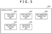
FIG. 5 is a functional block diagram of thecontrol section 160 of the head-mounteddisplay 100. Thecontrol section 160 includes a touchinput receiving unit 161, an inputposition adjusting unit 162, an inputinformation transmitting unit 163, an HMD imagedata receiving unit 164, and an HMDdisplay controlling unit 165. - The touch
input receiving unit 161 receives the input signal from thetouch pads 140. The inputposition adjusting unit 162 associates the position of the input received by the touchinput receiving unit 161 with the position of the area which, as part of the image displayed on thedisplay device 90, is assigned the input area of thetouch pads 140. The inputinformation transmitting unit 163 transmits to thegame device 10 the information indicative of the touch input position adjusted by the inputposition adjusting unit 162. - The HMD image
data receiving unit 164 receives from thegame device 10 the data of the image to be displayed on thedisplay device 90. The HMDdisplay controlling unit 165 causes thedisplay device 90 to display the image data received by the HMD imagedata receiving unit 164. -
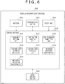
FIG. 6 is a functional block diagram of themobile information terminal 200. Themobile information terminal 200 includesbuttons 261, acommunication section 202, acontrol section 210, adata holding section 260, and atouch panel 262. Thecontrol section 210 includes a touchinput receiving unit 211, an inputposition adjusting unit 212, an inputinformation transmitting unit 213, a touch panel displayinformation receiving unit 214, a touch paneldisplay controlling unit 215, an HMD displayinformation generating unit 216, and an HMD displayinformation transmitting unit 217. These functional blocks are also implemented variously by hardware alone, by software alone, or by suitable combinations of both. - The
communication section 202 controls communications with thegame device 10. Thedata holding section 260 holds the program data of the application executed by themobile information terminal 200 as well as the data for use by the application. Thetouch panel 262 displays the image generated by thecontrol section 210, and detects the touch input from the user. - The
control section 210 executes a collaborative application for receiving the touch input to thetouch panel 262 as the input to the game which is executed by thegame device 10 and of which the image is displayed on the head-mounteddisplay 100. - The touch
input receiving unit 211 receives the input signal from thetouch panel 262. The inputposition adjusting unit 212 associates the position of the input received by the touchinput receiving unit 211 with the position of the area which, as part of the image displayed on thedisplay device 90 of the head-mounteddisplay 100, is assigned the input area of thetouch panel 262. The information about the area to which the input area of thetouch panel 262 is assigned is acquired from the head-mounteddisplay 100 or from thegame device 10 beforehand at the time of starting the collaborative application, for example. The inputinformation transmitting unit 213 transmits to thegame device 10 the information indicative of the touch input position adjusted by the inputposition adjusting unit 212. - The touch panel display
information receiving unit 214 receives from thegame device 10 the information to be displayed on thetouch panel 262. The touch paneldisplay controlling unit 215 causes thetouch panel 262 to display the information received by the touch panel displayinformation receiving unit 214. - The HMD display
information generating unit 216 generates the information to be displayed on the display device of the head-mounteddisplay 100. The HMD displayinformation generating unit 216 acquires diverse notification information from other applications executed by themobile information terminal 200, and generates display information out of the notification information in accordance with predetermined conditions. For example, when a mailing application of themobile information terminal 200 receives a mail, the HMD displayinformation generating unit 216 may generate the display information by extracting such information as the title of the mail, a character string made up of a predetermined number of characters at the beginning of the text of the mail, and the name of the sender. The HMD displayinformation transmitting unit 217 transmits to thegame device 10 the display information generated by the HMD displayinformation generating unit 216. In this embodiment, the information to be displayed on the display device of the head-mounteddisplay 100 is first transmitted to thegame device 10 that in turn generates the relevant image data. In another example, the information to be displayed on the display device of the head-mounteddisplay 100 may be directly transmitted to the head-mounteddisplay 100. The HMDdisplay controlling unit 165 of the head-mounteddisplay 100 may then cause thedisplay device 90 to display the transmitted information. -
FIG. 7 shows a typical image displayed on thedisplay device 90 of the head-mounteddisplay 100. Thedisplay device 90 of the head-mounteddisplay 100 displays the image of the game controlled by thegame device 10. -
FIG. 8 shows another typical image displayed on thedisplay device 90 of the head-mounteddisplay 100. Suppose that while the game is being played as shown inFIG. 7 , the user's surroundings are suddenly darkened. In that case, the HMD imagedata generating unit 313 of thegame device 10 generates a pitch-dark game image. Thedisplay device 90 of the head-mounteddisplay 100 proceeds to display the pitch-dark game image. -
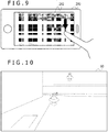
FIG. 9 shows thetouch panel 262 of themobile information terminal 200. In the example ofFIG. 9 , the touch panel displayinformation generating unit 315 of thegame device 10 generates information for causing thetouch panel 262 to display the same image as that displayed on thedisplay device 90 of the head-mounteddisplay 100. The touch paneldisplay controlling unit 215 of themobile information terminal 200 causes thetouch panel 262 to display the same image as that displayed on thedisplay device 90 of the head-mounteddisplay 100. Suppose that there is provided a function allowing night vision goggles to be virtually worn when thetouch panel 262 is flicked downward for input at any position and virtually taken off when thetouch panel 262 is flicked upward for input. When the user flicks thetouch panel 262 downward for input, the inputinformation transmitting unit 213 transmits to thegame device 10 information indicating that the downward flick input is made. -
FIG. 10 shows another typical image displayed on thedisplay device 90 of the head-mounteddisplay 100. When the user flicks thetouch panel 262 downward for input as shown inFIG. 9 and when thegame controlling unit 319 of thegame device 10 acquires information indicating that the downward flick input is made to thetouch panel 262, thegame controlling unit 319 instructs the HMD imagedata generating unit 313 to generate a night vision image by assuming that night vision goggles are virtually worn. The HMD imagedata generating unit 313 generates the night vision image that is displayed on thedisplay device 90 of the head-mounteddisplay 100 as shown inFIG. 10 . In this manner, the downward flick input and the upward flick input made to thetouch panel 262 are associated with actual goggles being worn in a downward motion and taken off in an upward motion by the user. This provides an intuitively comprehensible, user-friendly operating scheme. -
FIG. 11 shows another typical image displayed on thedisplay device 90 of the head-mounteddisplay 100. Thedisplay device 90 of the head-mounteddisplay 100 displays a game image that includesclouds 402 in the field of view. -
FIG. 12 shows anothertouch panel 262 of themobile information terminal 200. Suppose that there is provided a function for removing eachcloud 402 when the position on thetouch panel 262 at which thecloud 402 is displayed is swiped in any direction for input. When the user swipes thetouch panel 262 for input, the inputinformation transmitting unit 213 transmits the information indicating the swiped position to thegame device 10. -
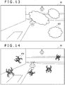
FIG. 13 shows another typical image displayed on thedisplay device 90 of the head-mounteddisplay 100. When the user swipes thetouch panel 262 for input as shown inFIG. 12 , thegame controlling unit 319 of thegame device 10 removes thecloud 402 displayed at the swiped position. The HMD imagedata generating unit 313 deletes from the game image the removedcloud 402 as shown inFIG. 13 . While inFIG. 12 the user swipes a right area in the game image displayed on thetouch panel 262, the swiped area corresponds to a left area on the screen as viewed from the user. Thegame controlling unit 319 thus deletes thecloud 402 displayed in the left area of the game image. If thetouch panel 262 displays the same game image as that displayed on the head-mounteddisplay 100, people watching thetouch panel 262 see the user swipe the right area of the image but will notice that thecloud 402 displayed in the left area of the game image is deleted. This will give the watching people a feeling of awkwardness. For this reason, thetouch panel 262 displays a mirror image horizontally flipping the game image displayed on the head-mounteddisplay 100. -
FIG. 14 shows another typical image displayed on thedisplay device 90 of the head-mounteddisplay 100. Thedisplay device 90 of the head-mounteddisplay 100 displays a gameimage showing spiders 404 clinging to the field of view. -
FIG. 15 shows anothertouch panel 262 of themobile information terminal 200. It is assumed that there is provided a function for removing thespiders 404 from any position swiped repeatedly in any direction for input on thetouch panel 262. When the user swipes thetouch panel 262 for input at least a predetermined number of times, the inputinformation transmitting unit 213 transmits to thegame device 10 the information indicating the swiped position and the number of times the position is swiped. In another example, every time thetouch panel 262 is swiped for input, the inputinformation transmitting unit 213 may transmit the information indicative of the swiped position to thegame device 10. Thegame controlling unit 319 of thegame device 10 may then determine whether or not the user has swiped for input at least a predetermined number of times. -
FIG. 16 shows another typical image displayed on thedisplay device 90 of the head-mounteddisplay 100. When the user swipes thetouch panel 262 for input at least a predetermined number of times as shown inFIG. 15 , thegame controlling unit 319 of thegame device 10 removes thespider 404 displayed on the location swiped for input at least the predetermined number of times. The HMD imagedata generating unit 313 deletes from the game image the removedspider 404 as shown inFIG. 16 . -
FIG. 17 shows another typical image displayed on thedisplay device 90 of the head-mounteddisplay 100. Thedisplay device 90 of the head-mounteddisplay 100 displays a game image showing aflash bang grenade 406 placed in the game field. -
FIG. 18 shows another typical image displayed on thedisplay device 90 of the head-mounteddisplay 100. When predetermined conditions are met for theflash bang grenade 406 to explode in the game status shown inFIG. 17 , thegame controlling unit 319 causes theflash bang grenade 406 to explode. The HMD imagedata generating unit 313 generates a game image in which a flash is produced by explosion of theflash bang grenade 406. Aflash 408 is displayed on thedisplay device 90 of the head-mounteddisplay 100. - When the
flash 408 occurs, the user may touch thetouch panel 262 in a manner covering both eyes by hand. This causes theflash 408 to disappear and the surrounding game field to be again displayed. If the user fails to touch thetouch panel 262 in the manner covering both eyes by hand, the eyes are blinded by theflash 408, and a stark white game image is displayed for a predetermined time period after theflash 408 disappears, causing the surrounding game field to disappear during that period. -
FIG. 19 shows anothertouch panel 262 of themobile information terminal 200. There is provided a function for shielding both eyes against theflash 408 when the user's palms touch each of a right-half area and a left-half area of thetouch panel 262. When thetouch panel 262 is thus touched for input, the inputinformation transmitting unit 213 transmits information indicative of the multiple touched positions to thegame device 10. Thegame controlling unit 319 determines whether or not the predetermined condition is met, i.e., whether or not the right-half area and the left-half area of thetouch panel 262 are touched by the palms at the moment of explosion. If it is determined that the two areas of thetouch panel 262 are touched for input, thegame controlling unit 319 causes the HMD imagedata generating unit 313 to again display the surrounding game field when theflash 408 disappears. If it is determined that the two areas are not touched for input, thegame controlling unit 319 causes the HMD imagedata generating unit 313 to display a stark white game image for a predetermined time period after theflash 408 disappears. -
FIG. 20 shows anothertouch panel 262 of themobile information terminal 200. When the user forms a V sign with the index and middle fingers near either of the left and right eyes and touches thetouch panel 262 with the two fingers as shown inFIG. 20 , a beam is emitted from the eyes of a player's character operated by the user or from the virtual eyes of the user in a first-person point-of-view game. -
FIG. 21 shows another typical image displayed on thedisplay device 90 of the head-mounteddisplay 100. There is provided a function for emitting a beam when two points in an area in a predetermined range of thetouch panel 262 are touched simultaneously for input. When thetouch panel 262 is thus touched for input, the inputinformation transmitting unit 213 transmits information indicative of the multiple touched positions to thegame device 10. Thegame controlling unit 319 determines whether or not two points are simultaneously touched for input inside a predetermined range of the panel. If it is determined that the two points within the predetermined rage are simultaneously touched for input, thegame controlling unit 319 causes the HMD imagedata generating unit 313 to display abeam 410 being emitted. If it is determined that the two points are not touched for input, thegame controlling unit 319 does not let the HMD imagedata generating unit 313 display the emission of thebeam 410. When thebeam 410 is emitted, thegame controlling unit 319 calculates the path of thebeam 410. If any object is found on the path, thegame controlling unit 319 performs a process that applies to when thebeam 410 hits the object. -
FIG. 22 is a schematic view showing anothertouch panel 262 of themobile information terminal 200. When the user touches any position for input on thetouch panel 262 with the fingers for at least a predetermined time period as shown inFIG. 22 , finger images are displayed on the touched positions in the game image shown on thedisplay device 90 of the head-mounteddisplay 100. -
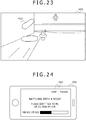
FIG. 23 shows another typical image displayed on thedisplay device 90 of the head-mounteddisplay 100. There is provided a function which, when the user touches any position for input on thetouch panel 262 for at least a predetermined time period or with at least a predetermined amount of pressure, then gives the visual effect of letting the user's fingers intrude from the background into a virtual world image displayed on thedisplay device 90 of the head-mounteddisplay 100. When thetouch panel 262 is touched for input, the inputinformation transmitting unit 213 transmits to thegame device 10 the information indicative of the multiple touched positions and the time spent in touching the positions or the pressure applied to the touch. Thegame controlling unit 319 determines whether or not thetouch panel 262 is touched for at least a predetermined time period or with at least a predetermined amount of pressure. If it is determined that the touch is thus performed for input, thegame controlling unit 319 causes the HMD imagedata generating unit 313 to display the user'sfingers 412 at the touched positions. If it is determined that the touch is not performed in this manner, thegame controlling unit 319 does not let the HMD imagedata generating unit 313 display the user'sfingers 412. Alternatively, the longer the touch is performed or the larger the amount of pressure the touch is performed with, the further the fingers may be shown intruding into the foreground. - As described above, when the user performs input to the
touch panel 262 in a manner corresponding to the actions by hand near the user's head in the real world, the results supposedly caused by the real-world actions are reflected in the display. This provides an intuitively comprehensible, user-friendly interface. - In the above example, the
touch panel 262 of themobile information terminal 200 displays the same image as that displayed on thedisplay device 90 of the head-mounteddisplay 100. This allows the people around the user concurrently to watch and enjoy the game being played by the user. This scheme is effective when parents wish to check the game played by their child, for example. Furthermore, because the game image need not to be displayed on thedisplay device 12 for the people around the user to watch the game, thedisplay device 12 may be used for other purposes. - The
touch panel 262 may display an image different from the image displayed on thedisplay device 90. What to display on thetouch panel 262 may be determined by receiving the user's instructions via the head-mounteddisplay 100,mobile information terminal 200, orgame device 10, or determined automatically by the head-mounteddisplay 100,mobile information terminal 200, orgame device 10. -
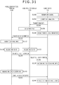
FIG. 24 shows a typical image displayed on thetouch panel 262 of themobile information terminal 200. In the example ofFIG. 24 , the information indicating the status of the game controlled by thegame controlling unit 319 is displayed on thetouch panel 262. The touch panel displayinformation generating unit 315 of thegame device 10 generates the display information by acquiring the information indicative of the game status under control of thegame controlling unit 319. Thetouch panel 262 in this example displays the game status as "battling with a boss," along with an indicator of the enemy character's strength as detailed information added to the game status and the user's message destined for the surrounding people. -
FIG. 25 shows another typical image displayed on thetouch panel 262 of themobile information terminal 200. Also in the example ofFIG. 25 , thetouch panel 262 displays the information indicative of the status of the game controlled by thegame controlling unit 319. The touch panel displayinformation generating unit 315 of thegame device 10 generates the display information by acquiring the information indicative of the game status under control of thegame controlling unit 319. Thetouch panel 262 displays the game status as "watching a movie," along with an indicator of the remaining time of the movie in seconds as detailed information added to the game status and the user's message destined for the surrounding people. -
FIG. 26 shows another typical image displayed on thetouch panel 262 of themobile information terminal 200. Also in the example ofFIG. 25 , thetouch panel 262 displays the information indicative of the status of the game controlled by thegame controlling unit 319. The touch panel displayinformation generating unit 315 of thegame device 10 generates the display information by acquiring the information indicative of the game status under control of thegame controlling unit 319. Thetouch panel 262 displays the play time of the game and an approximate time required for the next save point to be reached. This feature is effective where parents wish to limit their child's play time, for example. - As described above, the
touch panel 262 displays information indicating the status of the game being played or the movie being watched by the user wearing the head-mounteddisplay 100. The feature allows the people around the user to become aware of the user's status so that they can, for example, talk to the user when the status is interruptible. This reduces the occasions where the user is interrupted even though the interruption is unwanted, thereby allowing the user to experience the sense of immersion more effectively. -
FIG. 27 shows another typical image displayed on thetouch panel 262 of themobile information terminal 200. In the example ofFIG. 27 , thetouch panel 262 displays an image serving as a marker used by the capturedimage analyzing unit 318 to analyze the position and attitude of the head-mounteddisplay 100. This feature helps improve the accuracy in analyzing the position and attitude of the head-mounteddisplay 100. The feature is more effective if different markers are displayed on multiple touch panels set up at different locations. The image serving as the marker displayed on thetouch panel 262 may be any figure such as a barcode or a game character. As another alternative, the marker image may be the human eyes and their surroundings in a person's or a game character's face displayed as if the user is wearing the character's mask. This will entertain the people around the user. -
FIG. 28 shows another typical image displayed on thedisplay device 90 of the head-mounteddisplay 100. When the mailing application of themobile information terminal 200 receives a mail during the game, the HMD displayinformation generating unit 216 generates the information to be displayed on thedisplay device 90 of the head-mounteddisplay 100 by acquiring information about the received mail. The HMD displayinformation receiving unit 317 of thegame device 10 receives from themobile information terminal 200 the information to be displayed on thedisplay device 90 of the head-mounteddisplay 100. In turn, the HMD imagedata generating unit 313 generates the image data that includes the received information. In the example ofFIG. 28 , thedisplay device 90 of the head-mounteddisplay 100 displays, in adisplay area 502 at the bottom of the screen, the sender of the mail received by themobile information terminal 200, the title of the received mail, and a text portion at the beginning of the mail. - The settings for the information to be displayed on the
display device 90 of the head-mounteddisplay 100 may be received beforehand from the user via thetouch panel 262 of themobile information terminal 200. This allows the user to have a look at necessary information about themobile information terminal 200 while using the head-mounteddisplay 100. If necessary, the user may interrupt the viewing of the head-mounteddisplay 100 and use themobile information terminal 200. At this point, the information displayed on thedisplay device 90 of the head-mounteddisplay 100 need not to be displayed on thetouch panel 262 of themobile information terminal 200. This prevents the people around the user from viewing the user's information. - The position and size of the
display area 502 displaying the information received from themobile information terminal 200 may be determined depending on the current game status or in accordance with the settings received from the user. Because the aspect ratio of the image to be displayed does not coincide with that of the display area of thedisplay device 90, there may remain a blank area at the top, bottom, right margin, or left margin of the screen. That image-free area may then be utilized as thedisplay area 502. - The user may operate the
mobile information terminal 200 while viewing thedisplay device 90 of the head-mounteddisplay 100. Where the input function of thegame device 10 such as theinput device 20 is used to operate themobile information terminal 200, thegame device 10 transmits the input instructions received from theinput device 20 to themobile information terminal 200. The collaborative application of themobile information terminal 200 forwards the received input instructions to a target application such as the mailing application. Where the input function of the head-mounteddisplay 100 such as thetouch pads 140 is used to operate themobile information terminal 200, the head-mounteddisplay 100 transmits the input instructions received from thetouch pads 140, for example, directly or via thegame device 10 to themobile information terminal 200. Where thetouch panel 262 of themobile information terminal 200 is used to operate themobile information terminal 200, the input instructions are received directly by the target application or indirectly via the collaborative application. -
FIG. 29 shows the corresponding relation between the display area on thedisplay device 90 of the head-mounteddisplay 100 on one hand and the input areas of thetouch panel 262 and of eachtouch pad 140 on the other hand. As described above, this embodiment includesmultiple touch panels 262 andtouch pads 140. Thus, the inputposition adjusting unit 312 of thegame device 10 associates the position of the input to thetouch panel 262 and to eachtouch pad 140 with the position in the image displayed on thedisplay device 90 of the head-mounteddisplay 100. In the example ofFIG. 29 , inside the image displayed on thedisplay device 90 of the head-mounteddisplay 100, an area a is associated with thetouch panel 262 of themobile information terminal 200; an area b is associated with thetouch pad 140 disposed on the upper surface of the head-mounteddisplay 100; an area c is associated with thetouch pad 140 disposed on the left head side of the head-mounteddisplay 100; and an area d is associated with thetouch pad 140 disposed on the right head side of the head-mounteddisplay 100. In this case, it is preferred that the user's field of view coincide as much as possible with the actual locations at which thetouch panel 262 andtouch pads 140 are disposed. This provides an interface that allows the user to perform operations without becoming aware of inconsistencies between body sensation and visual sensation. - Each of the above display areas may differ in size or shape from the input area of the
touch panel 262 and of eachtouch pad 140. If that happens with thetouch panel 262, the inputposition adjusting unit 212 of themobile information terminal 200 associates the actual input position with the input position in the assigned input area. In the case of thetouch pads 140, the inputposition adjusting unit 162 of the head-mounteddisplay 100 associates the actual input position with the input position in the assigned input area. -
FIG. 30 shows another typical image displayed on thedisplay device 90 of the head-mounteddisplay 100. When the inputinformation receiving unit 311 receives input information, the inputposition adjusting unit 312 of thegame device 10 displays amarker 504 indicating the input position at the adjusted position, together with anarea frame 506 corresponding to thetouch panel 262 or thetouch pad 140 that has received the input. In this manner, where there aremultiple touch pads 140 as well as thetouch panels 262, the user is shown comprehensibly which of thetouch panels 262 andtouch pads 140 to touch to make input to the desired position. The user is also shown comprehensibly where to touch on thetouch panel 262 or on thetouch pad 140. -
FIG. 31 is a sequence diagram showing the steps constituting the display control method according to the embodiment. Thegame controlling unit 319 of thegame device 10 controls the game (S100). The HMD imagedata generating unit 313 generates the image data to be displayed on the head-mounted display 100 (S102). The HMD imagedata transmitting unit 314 transmits the image data to the head-mounted display 100 (S104). The HMDdisplay controlling unit 165 of the head-mounteddisplay 100 displays the image data on the display device 90 (S106). - The touch panel display
information generating unit 315 of thegame device 10 generates information for displaying game status and other information on thetouch panel 262 of the mobile information terminal 200 (S108). The touch panel displayinformation transmitting unit 316 transmits the display information to the mobile information terminal 200 (S110). The touch paneldisplay controlling unit 215 of themobile information terminal 200 displays the display information on the touch panel 262 (S112). - When the user touches the
touch panel 262 of themobile information terminal 200 for input, the touchinput receiving unit 211 receives the input (S120). The inputposition adjusting unit 212 adjusts the position of the touch input, and the inputinformation transmitting unit 213 transmits the input information to the game device 10 (S124). When the user touches anytouch pad 140 of the head-mounteddisplay 100 for input, the touchinput receiving unit 161 receives the input (S122). The inputposition adjusting unit 162 adjusts the position of the touch input, and the inputinformation transmitting unit 163 transmits the input information to the game device 10 (S126). When the inputinformation receiving unit 311 of thegame device 10 receives the input information from themobile information terminal 200 or from the head-mounteddisplay 100, the inputposition adjusting unit 312 adjusts the position of the touch input, and thegame controlling unit 319 causes the touch input to be reflected in game control (S128). Control is then returned to step S100. - The HMD display
information generating unit 216 generates the information to be displayed on the head-mounteddisplay 100 when, for example, themobile information terminal 200 receives a mail (S140). In this case, the HMD displayinformation transmitting unit 217 transmits the display information to the game device 10 (S142). When the HMD displayinformation receiving unit 317 of thegame device 10 receives the display information from themobile information terminal 200, the HMD imagedata generating unit 313 causes the display information to be reflected in the display (S144). Control is then returned to step S102. - The present invention was described above using specific embodiment as an example. It is to be understood by those skilled in the art that suitable combinations of constituent elements and processes of the embodiment may lead to further variations of the present invention and that such variations also fall within the scope of this invention.
- In the above examples, a monocular vision image is displayed on the
display device 90 of the head-mounteddisplay 100. As an alternative, a binocular stereoscopic vision image may be displayed. In this case, the binocular stereoscopic vision image may be displayed on thetouch panel 262 of themobile information terminal 200 while the monocular vision image may be displayed on thetouch panel 262. - In the above examples, the
game device 10 controls the game to generate the image data to be displayed on thedisplay device 90 of the head-mounteddisplay 100. Alternatively, the head-mounteddisplay 100 may be configured to control the game to generate the image data. In this case, thegame device 10 is not needed. Themobile information terminal 200 may directly communicate with the head-mounteddisplay 100 without the intervention of thegame device 10. - Whereas the game system uses the head-mounted
display 100 in the above examples, the techniques described in conjunction with the embodiment may be used to display contents other than the games. In a display system that does not include any dedicated input device such as a game controller, the head-mounteddisplay 100 according to the embodiment may be used to input the user's instructions easily via the touch pads or the touch panel of the mobile information terminal. -
- 10
- Game device
- 90
- Display device
- 100
- Head-mounted display
- 140
- Touch pad
- 161
- Touch input receiving unit
- 162
- Input position adjusting unit
- 163
- Input information transmitting unit
- 164
- HMD image data receiving unit
- 165
- HMD display controlling unit
- 200
- Mobile information terminal
- 211
- Touch input receiving unit
- 212
- Input position adjusting unit
- 213
- Input information transmitting unit
- 214
- Touch panel display information receiving unit
- 215
- Touch panel display controlling unit
- 216
- HMD display information generating unit
- 217
- HMD display information transmitting unit
- 262
- Touch panel
- 311
- Input information receiving unit
- 312
- Input position adjusting unit
- 313
- HMD image data generating unit
- 314
- HMD image data transmitting unit
- 315
- Touch panel display information generating unit
- 316
- Touch panel display information transmitting unit
- 317
- HMD display information receiving unit
- 319
- Game controlling unit
- The present invention can be applied to implementing the head-mounted display.
Claims (12)
- A head-mounted display wearable on the head of a user, the head-mounted display comprising:a display device configured to be disposed on an inner surface of the head-mounted display worn by the user on the head;an input device configured to be disposed on an outer surface of the head-mounted display worn by the user on the head, the input device being able to detect contact with or proximity of a body part of the user; anda display controlling unit configured to acquire data of an image generated based on input information indicative of the input device detecting the contact with or the proximity of the body part of the user, the display controlling unit further causing the display device to display the acquired image data.
- The head-mounted display according to claim 1, further comprising
a plurality of the input devices,
wherein an input area of at least one of the input devices is associated with one of a plurality of divided areas making up the image. - The head-mounted display according to claim 1 or 2,
wherein the input device is a touch panel including a touch pad doubling as a display panel, the touch pad being able to detect the contact with or the proximity of the body part of the user, and
the display panel displays an image related to the image displayed on the display device. - The head-mounted display according to any one of claims 1 to 3,
wherein the input device is a mobile information terminal having a processing apparatus and a touch panel including a touch pad doubling as a display panel, the touch pad being able to detect the contact with or the proximity of the body part of the user, and
the display device is able to display information about an application executed by the processing apparatus. - The head-mounted display according to any one of claims 1 to 4,
wherein, when the user performs input to the input device in a manner corresponding to an action performed by hand near the head in the real world, the image is generated to reflect the result supposedly caused by the action in the real world. - A display control program causing a computer to function as:an acquiring unit configured to acquire data of an image generated based on input information indicative of an input device detecting contact with or proximity of a body part of a user wearing a head-mounted display on the head, the input device being disposed on an outer surface of the head-mounted display; anda display controlling unit configured to display the image data acquired by the acquiring unit on a display device disposed on an inner surface of the head-mounted display worn by the user on the head.
- A display control method comprising:a step of causing an acquiring unit to acquire data of an image generated based on input information indicative of an input device detecting contact with or proximity of a body part of a user wearing a head-mounted display on the head, the input device being disposed on an outer surface of the head-mounted display; anda step of causing a display controlling unit to display the image data acquired by the acquiring unit on a display device disposed on an inner surface of the head-mounted display worn by the user on the head.
- A computer-readable recording medium that records the display control program according to claim 6.
- A display system comprising:a head-mounted display configured to be wearable on the head of a user; andan image processing apparatus configured to generate an image to be displayed on the head-mounted display,wherein the head-mounted display includesa display device configured to be disposed on an inner surface of the head-mounted display worn by the user on the head,an input device configured to be disposed on an outer surface of the head-mounted display worn by the user on the head, the input device being able to detect contact with or proximity of a body part of the user, anda display controlling unit configured to acquire from the image processing apparatus data of an image generated based on input information indicative of the input device detecting the contact with or the proximity of the body part of the user, the display controlling unit further causing the display device to display the acquired image data, andthe image processing apparatus includesan image generating unit configured to acquire the input information and generate the image data based on the input information.
- A head-mounted display wearable on the head of a user, comprising:a display device configured to be disposed on an inner surface of the head-mounted display worn by the user on the head; anda display controlling unit configured to acquire data of an image generated based on input information indicative of an input device detecting contact with or proximity of a body part of the user wearing the head-mounted display on the head, the input device being disposed on an outer surface of the head-mounted display, the display controlling unit further causing the display device to display the acquired image data.
- A mobile information terminal portable by a user, comprising:an input device configured to be able to detect contact with or proximity of a body part of the user; anda communication section configured to transmit input information indicative of the input device detecting the contact with or the proximity of the body part of the user wearing a head-mounted display on the head, the mobile information terminal being disposed on an outer surface of the head-mounted display worn by the user on the head, to an apparatus generating an image to be displayed on the head-mounted display based on the input information.
- An image processing apparatus comprising:a receiving unit configured to receive input information indicative of an input device detecting contact with orproximity of a body part of a user wearing a head-mounted display on the head, the input device being disposed on an outer surface of the head-mounted display;a generating unit configured to generate data of an image based on the input information received by the receiving unit,the image being destined to be displayed on a display device disposed on an inner surface of the head-mounted display worn by the user on the head; anda transmitting unit configured to transmit to the head-mounted display the image data generated by the generating unit.
Applications Claiming Priority (2)
| Application Number | Priority Date | Filing Date | Title |
|---|---|---|---|
| JP2014215565A JP6340301B2 (en) | 2014-10-22 | 2014-10-22 | Head mounted display, portable information terminal, image processing apparatus, display control program, display control method, and display system |
| PCT/JP2015/079276 WO2016063801A1 (en) | 2014-10-22 | 2015-10-16 | Head mounted display, mobile information terminal, image processing device, display control program, and display control method |
Publications (3)
| Publication Number | Publication Date |
|---|---|
| EP3211513A1 true EP3211513A1 (en) | 2017-08-30 |
| EP3211513A4 EP3211513A4 (en) | 2018-07-25 |
| EP3211513B1 EP3211513B1 (en) | 2021-01-13 |
Family
ID=55760839
Family Applications (1)
| Application Number | Title | Priority Date | Filing Date |
|---|---|---|---|
| EP15852710.1A Active EP3211513B1 (en) | 2014-10-22 | 2015-10-16 | Head mounted display, mobile information terminal, image processing device, display control program, and display control method |
Country Status (5)
| Country | Link |
|---|---|
| US (2) | US10379605B2 (en) |
| EP (1) | EP3211513B1 (en) |
| JP (1) | JP6340301B2 (en) |
| CN (1) | CN106817913B (en) |
| WO (1) | WO2016063801A1 (en) |
Cited By (1)
| Publication number | Priority date | Publication date | Assignee | Title |
|---|---|---|---|---|
| US20180004312A1 (en) * | 2016-06-29 | 2018-01-04 | Lg Electronics Inc. | Terminal and controlling method thereof |
Families Citing this family (18)
| Publication number | Priority date | Publication date | Assignee | Title |
|---|---|---|---|---|
| JP6567324B2 (en) * | 2015-05-21 | 2019-08-28 | シャープ株式会社 | Image display device and head mounted display |
| JP6668170B2 (en) * | 2016-06-07 | 2020-03-18 | 株式会社ソニー・インタラクティブエンタテインメント | Information processing apparatus, information processing method, and computer program |
| US10245507B2 (en) | 2016-06-13 | 2019-04-02 | Sony Interactive Entertainment Inc. | Spectator management at view locations in virtual reality environments |
| WO2018194569A1 (en) * | 2017-04-18 | 2018-10-25 | Hewlett-Packard Development Company, L.P. | Virtual input devices for pressure sensitive surfaces |
| JP6996285B2 (en) * | 2017-12-25 | 2022-01-17 | 凸版印刷株式会社 | Methods, Portable Terminals, and Programs for Portable Terminals to Provide User Interfaces for Controlling the Playback of VR Content by VR Content Playback Devices. |
| JP6582205B2 (en) * | 2018-02-28 | 2019-10-02 | 株式会社コナミデジタルエンタテインメント | Information processing apparatus, information processing apparatus program, head mounted display, and information processing system |
| JP7403943B2 (en) * | 2018-05-28 | 2023-12-25 | 株式会社コロプラ | Game program, game method, and information processing terminal |
| KR102185338B1 (en) * | 2018-06-15 | 2020-12-01 | 주식회사 룩시드랩스 | Face supporting mask and head mounted display apparatus comprising the same |
| KR102312185B1 (en) * | 2018-08-28 | 2021-10-13 | 주식회사 룩시드랩스 | Detachable function module for biometric data acquisition and head mounted display apparatus comprising the same |
| US11906740B2 (en) | 2018-09-20 | 2024-02-20 | Sony Interactive Entertainment Inc. | Display system, program, display method, and head mounted device |
| JP7385238B2 (en) * | 2019-01-07 | 2023-11-22 | 株式会社mediVR | Rehabilitation support device, rehabilitation support method, and rehabilitation support program |
| EP3734416A1 (en) * | 2019-04-30 | 2020-11-04 | XRSpace CO., LTD. | Head mounted display system capable of indicating a tracking unit to track a hand gesture or a hand movement of a user or not, related method and related non-transitory computer readable storage medium |
| JP7384576B2 (en) * | 2019-06-06 | 2023-11-21 | 株式会社ソニー・インタラクティブエンタテインメント | Display control device, display control method, and display control program |
| US11740742B2 (en) * | 2019-09-23 | 2023-08-29 | Apple Inc. | Electronic devices with finger sensors |
| CN113238708B (en) * | 2021-05-17 | 2024-02-23 | 杭州灵伴科技有限公司 | A method and device for displaying touch operation information in a head-mounted display device |
| CN115357121A (en) * | 2022-08-29 | 2022-11-18 | 歌尔科技有限公司 | Control method, system and device of head-mounted wearable equipment and storage medium |
| CN115878059A (en) * | 2022-10-20 | 2023-03-31 | 北京凌宇智控科技有限公司 | Display method of information code on head-mounted display equipment |
| US20250303291A1 (en) * | 2024-04-01 | 2025-10-02 | Sony Interactive Entertainment Inc. | Enabling the tracking of a remote-play client in virtual reality without additional sensors |
Family Cites Families (25)
| Publication number | Priority date | Publication date | Assignee | Title |
|---|---|---|---|---|
| US5991085A (en) * | 1995-04-21 | 1999-11-23 | I-O Display Systems Llc | Head-mounted personal visual display apparatus with image generator and holder |
| JP2003289484A (en) | 2002-03-28 | 2003-10-10 | Sanyo Electric Co Ltd | Eye mount video display apparatus and operating apparatus |
| JP2004085476A (en) | 2002-08-28 | 2004-03-18 | Sony Corp | Head tracking method and apparatus |
| KR20050025083A (en) | 2003-09-03 | 2005-03-11 | 휴먼센스 주식회사 | Hmd apparatus having a memory slot built-in thereof |
| JP2007310599A (en) * | 2006-05-17 | 2007-11-29 | Nikon Corp | Video display device |
| JP2008028552A (en) | 2006-07-19 | 2008-02-07 | Nikon Corp | Display device |
| US8957835B2 (en) | 2008-09-30 | 2015-02-17 | Apple Inc. | Head-mounted display apparatus for retaining a portable electronic device with display |
| US8665177B2 (en) * | 2010-02-05 | 2014-03-04 | Kopin Corporation | Touch sensor for controlling eyewear |
| WO2012011893A1 (en) | 2010-07-20 | 2012-01-26 | Empire Technology Development Llc | Augmented reality proximity sensing |
| WO2012040386A1 (en) * | 2010-09-21 | 2012-03-29 | 4Iiii Innovations Inc. | Head-mounted peripheral vision display systems and methods |
| JP2012186660A (en) * | 2011-03-06 | 2012-09-27 | Sony Corp | Head mounted display |
| US20120249587A1 (en) * | 2011-04-04 | 2012-10-04 | Anderson Glen J | Keyboard avatar for heads up display (hud) |
| JP5978592B2 (en) * | 2011-10-26 | 2016-08-24 | ソニー株式会社 | Head mounted display and display control method |
| JP2013125247A (en) | 2011-12-16 | 2013-06-24 | Sony Corp | Head-mounted display and information display apparatus |
| US8970960B2 (en) * | 2011-12-22 | 2015-03-03 | Mattel, Inc. | Augmented reality head gear |
| JP5884502B2 (en) | 2012-01-18 | 2016-03-15 | ソニー株式会社 | Head mounted display |
| JP6136090B2 (en) | 2012-03-13 | 2017-05-31 | 株式会社ニコン | Electronic device and display device |
| JP2013258614A (en) | 2012-06-13 | 2013-12-26 | Sony Computer Entertainment Inc | Image generation device and image generation method |
| JP5953963B2 (en) | 2012-06-13 | 2016-07-20 | ソニー株式会社 | Head-mounted image display device |
| CN103677579B (en) * | 2012-09-03 | 2019-11-26 | 联想(北京)有限公司 | Electronic equipment and control method |
| JP5962403B2 (en) * | 2012-10-01 | 2016-08-03 | ソニー株式会社 | Information processing apparatus, display control method, and program |
| TWI492133B (en) * | 2012-11-26 | 2015-07-11 | Capacitor sensing circuit | |
| CN103914128B (en) * | 2012-12-31 | 2017-12-29 | 联想(北京)有限公司 | Wear-type electronic equipment and input method |
| JP6318462B2 (en) * | 2013-01-30 | 2018-05-09 | 株式会社ニコン | Display device |
| CN109828671B (en) | 2014-01-23 | 2022-02-22 | 索尼公司 | Image display device and image display method |
-
2014
- 2014-10-22 JP JP2014215565A patent/JP6340301B2/en active Active
-
2015
- 2015-10-16 WO PCT/JP2015/079276 patent/WO2016063801A1/en not_active Ceased
- 2015-10-16 US US15/517,316 patent/US10379605B2/en active Active
- 2015-10-16 CN CN201580055928.2A patent/CN106817913B/en active Active
- 2015-10-16 EP EP15852710.1A patent/EP3211513B1/en active Active
-
2019
- 2019-06-21 US US16/448,434 patent/US10620699B2/en active Active
Cited By (1)
| Publication number | Priority date | Publication date | Assignee | Title |
|---|---|---|---|---|
| US20180004312A1 (en) * | 2016-06-29 | 2018-01-04 | Lg Electronics Inc. | Terminal and controlling method thereof |
Also Published As
| Publication number | Publication date |
|---|---|
| US10379605B2 (en) | 2019-08-13 |
| JP6340301B2 (en) | 2018-06-06 |
| WO2016063801A1 (en) | 2016-04-28 |
| CN106817913B (en) | 2020-10-09 |
| CN106817913A (en) | 2017-06-09 |
| US20190310703A1 (en) | 2019-10-10 |
| US10620699B2 (en) | 2020-04-14 |
| EP3211513A4 (en) | 2018-07-25 |
| EP3211513B1 (en) | 2021-01-13 |
| JP2016081476A (en) | 2016-05-16 |
| US20170308158A1 (en) | 2017-10-26 |
Similar Documents
| Publication | Publication Date | Title |
|---|---|---|
| US10620699B2 (en) | Head mounted display, mobile information terminal, image processing apparatus, display control program, display control method, and display system | |
| CN108292490B (en) | Display control device and display control method | |
| EP3163406A1 (en) | Tethering-type head-mounted display and method for controlling the same | |
| JP2020044339A (en) | Display control program, display control device, and display control method | |
| US20170038838A1 (en) | Information processing system and information processing method | |
| US11567330B2 (en) | Display control apparatus, display control method, and display control program | |
| JP2016158795A (en) | Display control program, display control apparatus, and display control method | |
| JP2016158794A (en) | Display control program, display control apparatus, and display control method | |
| CN111937045A (en) | Information processing apparatus, information processing method, and recording medium | |
| US11360545B2 (en) | Information processing device, information processing method, and program | |
| JP2018206029A (en) | Information processing method, apparatus, and program for implementing that information processing method in computer | |
| WO2020105269A1 (en) | Information processing device, information processing method, and program | |
| JP6457446B2 (en) | Method and apparatus for supporting communication in virtual space, and program for causing computer to execute the method | |
| EP3734418A1 (en) | Head mounted display system capable of displaying a virtual scene and a map of a real environment in a picture-in-picture mode, related method and related non-transitory computer readable storage medium | |
| CN113617023B (en) | Programs, information processing methods, information processing devices, and information processing systems | |
| JP2018160249A (en) | Head mounted display system, head mounted display, display control program, and display control method | |
| JP2018206353A (en) | Information processing method, apparatus, and program for implementing that information processing method in computer | |
| JP2019033906A (en) | Information processing method, program, and computer | |
| JP6711891B2 (en) | Display control program, display control device, and display control method | |
| US12429945B2 (en) | Information processing apparatus and adjustment screen display method | |
| EP4610795A1 (en) | Information processing device and information processing method | |
| US20260003436A1 (en) | Information processing device, information processing system, storage medium storing information processing program, and information processing method | |
| US20260105700A1 (en) | Information processing apparatus and information processing method | |
| JP6891319B2 (en) | Display control device and display control method | |
| KR20250095638A (en) | Input device, control device, control method, information processing device and information processing method |
Legal Events
| Date | Code | Title | Description |
|---|---|---|---|
| STAA | Information on the status of an ep patent application or granted ep patent |
Free format text: STATUS: THE INTERNATIONAL PUBLICATION HAS BEEN MADE |
|
| PUAI | Public reference made under article 153(3) epc to a published international application that has entered the european phase |
Free format text: ORIGINAL CODE: 0009012 |
|
| STAA | Information on the status of an ep patent application or granted ep patent |
Free format text: STATUS: REQUEST FOR EXAMINATION WAS MADE |
|
| 17P | Request for examination filed |
Effective date: 20170327 |
|
| AK | Designated contracting states |
Kind code of ref document: A1 Designated state(s): AL AT BE BG CH CY CZ DE DK EE ES FI FR GB GR HR HU IE IS IT LI LT LU LV MC MK MT NL NO PL PT RO RS SE SI SK SM TR |
|
| AX | Request for extension of the european patent |
Extension state: BA ME |
|
| DAV | Request for validation of the european patent (deleted) | ||
| DAX | Request for extension of the european patent (deleted) | ||
| RIC1 | Information provided on ipc code assigned before grant |
Ipc: A63F 13/533 20140101ALI20180403BHEP Ipc: A63F 13/214 20140101AFI20180403BHEP Ipc: G06F 3/048 20130101ALI20180403BHEP Ipc: A63F 13/24 20140101ALI20180403BHEP Ipc: A63F 13/25 20140101ALI20180403BHEP Ipc: G06F 3/01 20060101ALI20180403BHEP Ipc: G06F 3/0488 20130101ALI20180403BHEP Ipc: A63F 13/426 20140101ALI20180403BHEP Ipc: G09G 5/00 20060101ALI20180403BHEP |
|
| REG | Reference to a national code |
Ref country code: DE Ref legal event code: R079 Ref document number: 602015064836 Country of ref document: DE Free format text: PREVIOUS MAIN CLASS: G06F0003048000 Ipc: A63F0013214000 |
|
| A4 | Supplementary search report drawn up and despatched |
Effective date: 20180621 |
|
| RIC1 | Information provided on ipc code assigned before grant |
Ipc: A63F 13/214 20140101AFI20180615BHEP Ipc: G06F 3/0488 20130101ALI20180615BHEP Ipc: A63F 13/426 20140101ALI20180615BHEP Ipc: A63F 13/24 20140101ALI20180615BHEP Ipc: G09G 5/00 20060101ALI20180615BHEP Ipc: G06F 3/01 20060101ALI20180615BHEP Ipc: A63F 13/25 20140101ALI20180615BHEP Ipc: A63F 13/533 20140101ALI20180615BHEP Ipc: G06F 3/048 20130101ALI20180615BHEP |
|
| STAA | Information on the status of an ep patent application or granted ep patent |
Free format text: STATUS: EXAMINATION IS IN PROGRESS |
|
| 17Q | First examination report despatched |
Effective date: 20190729 |
|
| GRAP | Despatch of communication of intention to grant a patent |
Free format text: ORIGINAL CODE: EPIDOSNIGR1 |
|
| STAA | Information on the status of an ep patent application or granted ep patent |
Free format text: STATUS: GRANT OF PATENT IS INTENDED |
|
| INTG | Intention to grant announced |
Effective date: 20200813 |
|
| GRAS | Grant fee paid |
Free format text: ORIGINAL CODE: EPIDOSNIGR3 |
|
| GRAA | (expected) grant |
Free format text: ORIGINAL CODE: 0009210 |
|
| STAA | Information on the status of an ep patent application or granted ep patent |
Free format text: STATUS: THE PATENT HAS BEEN GRANTED |
|
| AK | Designated contracting states |
Kind code of ref document: B1 Designated state(s): AL AT BE BG CH CY CZ DE DK EE ES FI FR GB GR HR HU IE IS IT LI LT LU LV MC MK MT NL NO PL PT RO RS SE SI SK SM TR |
|
| REG | Reference to a national code |
Ref country code: GB Ref legal event code: FG4D |
|
| REG | Reference to a national code |
Ref country code: CH Ref legal event code: EP |
|
| REG | Reference to a national code |
Ref country code: IE Ref legal event code: FG4D |
|
| REG | Reference to a national code |
Ref country code: DE Ref legal event code: R096 Ref document number: 602015064836 Country of ref document: DE |
|
| REG | Reference to a national code |
Ref country code: AT Ref legal event code: REF Ref document number: 1354118 Country of ref document: AT Kind code of ref document: T Effective date: 20210215 |
|
| REG | Reference to a national code |
Ref country code: AT Ref legal event code: MK05 Ref document number: 1354118 Country of ref document: AT Kind code of ref document: T Effective date: 20210113 |
|
| REG | Reference to a national code |
Ref country code: NL Ref legal event code: MP Effective date: 20210113 |
|
| REG | Reference to a national code |
Ref country code: LT Ref legal event code: MG9D |
|
| PG25 | Lapsed in a contracting state [announced via postgrant information from national office to epo] |
Ref country code: PT Free format text: LAPSE BECAUSE OF FAILURE TO SUBMIT A TRANSLATION OF THE DESCRIPTION OR TO PAY THE FEE WITHIN THE PRESCRIBED TIME-LIMIT Effective date: 20210513 Ref country code: NO Free format text: LAPSE BECAUSE OF FAILURE TO SUBMIT A TRANSLATION OF THE DESCRIPTION OR TO PAY THE FEE WITHIN THE PRESCRIBED TIME-LIMIT Effective date: 20210413 Ref country code: LT Free format text: LAPSE BECAUSE OF FAILURE TO SUBMIT A TRANSLATION OF THE DESCRIPTION OR TO PAY THE FEE WITHIN THE PRESCRIBED TIME-LIMIT Effective date: 20210113 Ref country code: HR Free format text: LAPSE BECAUSE OF FAILURE TO SUBMIT A TRANSLATION OF THE DESCRIPTION OR TO PAY THE FEE WITHIN THE PRESCRIBED TIME-LIMIT Effective date: 20210113 Ref country code: FI Free format text: LAPSE BECAUSE OF FAILURE TO SUBMIT A TRANSLATION OF THE DESCRIPTION OR TO PAY THE FEE WITHIN THE PRESCRIBED TIME-LIMIT Effective date: 20210113 Ref country code: GR Free format text: LAPSE BECAUSE OF FAILURE TO SUBMIT A TRANSLATION OF THE DESCRIPTION OR TO PAY THE FEE WITHIN THE PRESCRIBED TIME-LIMIT Effective date: 20210414 Ref country code: BG Free format text: LAPSE BECAUSE OF FAILURE TO SUBMIT A TRANSLATION OF THE DESCRIPTION OR TO PAY THE FEE WITHIN THE PRESCRIBED TIME-LIMIT Effective date: 20210413 |
|
| PG25 | Lapsed in a contracting state [announced via postgrant information from national office to epo] |
Ref country code: SE Free format text: LAPSE BECAUSE OF FAILURE TO SUBMIT A TRANSLATION OF THE DESCRIPTION OR TO PAY THE FEE WITHIN THE PRESCRIBED TIME-LIMIT Effective date: 20210113 Ref country code: AT Free format text: LAPSE BECAUSE OF FAILURE TO SUBMIT A TRANSLATION OF THE DESCRIPTION OR TO PAY THE FEE WITHIN THE PRESCRIBED TIME-LIMIT Effective date: 20210113 Ref country code: RS Free format text: LAPSE BECAUSE OF FAILURE TO SUBMIT A TRANSLATION OF THE DESCRIPTION OR TO PAY THE FEE WITHIN THE PRESCRIBED TIME-LIMIT Effective date: 20210113 Ref country code: LV Free format text: LAPSE BECAUSE OF FAILURE TO SUBMIT A TRANSLATION OF THE DESCRIPTION OR TO PAY THE FEE WITHIN THE PRESCRIBED TIME-LIMIT Effective date: 20210113 Ref country code: PL Free format text: LAPSE BECAUSE OF FAILURE TO SUBMIT A TRANSLATION OF THE DESCRIPTION OR TO PAY THE FEE WITHIN THE PRESCRIBED TIME-LIMIT Effective date: 20210113 |
|
| PG25 | Lapsed in a contracting state [announced via postgrant information from national office to epo] |
Ref country code: IS Free format text: LAPSE BECAUSE OF FAILURE TO SUBMIT A TRANSLATION OF THE DESCRIPTION OR TO PAY THE FEE WITHIN THE PRESCRIBED TIME-LIMIT Effective date: 20210513 |
|
| REG | Reference to a national code |
Ref country code: DE Ref legal event code: R097 Ref document number: 602015064836 Country of ref document: DE |
|
| PG25 | Lapsed in a contracting state [announced via postgrant information from national office to epo] |
Ref country code: EE Free format text: LAPSE BECAUSE OF FAILURE TO SUBMIT A TRANSLATION OF THE DESCRIPTION OR TO PAY THE FEE WITHIN THE PRESCRIBED TIME-LIMIT Effective date: 20210113 Ref country code: CZ Free format text: LAPSE BECAUSE OF FAILURE TO SUBMIT A TRANSLATION OF THE DESCRIPTION OR TO PAY THE FEE WITHIN THE PRESCRIBED TIME-LIMIT Effective date: 20210113 Ref country code: SM Free format text: LAPSE BECAUSE OF FAILURE TO SUBMIT A TRANSLATION OF THE DESCRIPTION OR TO PAY THE FEE WITHIN THE PRESCRIBED TIME-LIMIT Effective date: 20210113 |
|
| PLBE | No opposition filed within time limit |
Free format text: ORIGINAL CODE: 0009261 |
|
| STAA | Information on the status of an ep patent application or granted ep patent |
Free format text: STATUS: NO OPPOSITION FILED WITHIN TIME LIMIT |
|
| PG25 | Lapsed in a contracting state [announced via postgrant information from national office to epo] |
Ref country code: DK Free format text: LAPSE BECAUSE OF FAILURE TO SUBMIT A TRANSLATION OF THE DESCRIPTION OR TO PAY THE FEE WITHIN THE PRESCRIBED TIME-LIMIT Effective date: 20210113 Ref country code: SK Free format text: LAPSE BECAUSE OF FAILURE TO SUBMIT A TRANSLATION OF THE DESCRIPTION OR TO PAY THE FEE WITHIN THE PRESCRIBED TIME-LIMIT Effective date: 20210113 Ref country code: RO Free format text: LAPSE BECAUSE OF FAILURE TO SUBMIT A TRANSLATION OF THE DESCRIPTION OR TO PAY THE FEE WITHIN THE PRESCRIBED TIME-LIMIT Effective date: 20210113 |
|
| 26N | No opposition filed |
Effective date: 20211014 |
|
| PG25 | Lapsed in a contracting state [announced via postgrant information from national office to epo] |
Ref country code: AL Free format text: LAPSE BECAUSE OF FAILURE TO SUBMIT A TRANSLATION OF THE DESCRIPTION OR TO PAY THE FEE WITHIN THE PRESCRIBED TIME-LIMIT Effective date: 20210113 Ref country code: ES Free format text: LAPSE BECAUSE OF FAILURE TO SUBMIT A TRANSLATION OF THE DESCRIPTION OR TO PAY THE FEE WITHIN THE PRESCRIBED TIME-LIMIT Effective date: 20210113 |
|
| PG25 | Lapsed in a contracting state [announced via postgrant information from national office to epo] |
Ref country code: SI Free format text: LAPSE BECAUSE OF FAILURE TO SUBMIT A TRANSLATION OF THE DESCRIPTION OR TO PAY THE FEE WITHIN THE PRESCRIBED TIME-LIMIT Effective date: 20210113 |
|
| PG25 | Lapsed in a contracting state [announced via postgrant information from national office to epo] |
Ref country code: IT Free format text: LAPSE BECAUSE OF FAILURE TO SUBMIT A TRANSLATION OF THE DESCRIPTION OR TO PAY THE FEE WITHIN THE PRESCRIBED TIME-LIMIT Effective date: 20210113 |
|
| REG | Reference to a national code |
Ref country code: DE Ref legal event code: R119 Ref document number: 602015064836 Country of ref document: DE |
|
| PG25 | Lapsed in a contracting state [announced via postgrant information from national office to epo] |
Ref country code: IS Free format text: LAPSE BECAUSE OF FAILURE TO SUBMIT A TRANSLATION OF THE DESCRIPTION OR TO PAY THE FEE WITHIN THE PRESCRIBED TIME-LIMIT Effective date: 20210513 |
|
| REG | Reference to a national code |
Ref country code: CH Ref legal event code: PL |
|
| REG | Reference to a national code |
Ref country code: BE Ref legal event code: MM Effective date: 20211031 |
|
| PG25 | Lapsed in a contracting state [announced via postgrant information from national office to epo] |
Ref country code: MC Free format text: LAPSE BECAUSE OF FAILURE TO SUBMIT A TRANSLATION OF THE DESCRIPTION OR TO PAY THE FEE WITHIN THE PRESCRIBED TIME-LIMIT Effective date: 20210113 |
|
| PG25 | Lapsed in a contracting state [announced via postgrant information from national office to epo] |
Ref country code: LU Free format text: LAPSE BECAUSE OF NON-PAYMENT OF DUE FEES Effective date: 20211016 Ref country code: DE Free format text: LAPSE BECAUSE OF NON-PAYMENT OF DUE FEES Effective date: 20220503 Ref country code: BE Free format text: LAPSE BECAUSE OF NON-PAYMENT OF DUE FEES Effective date: 20211031 |
|
| PG25 | Lapsed in a contracting state [announced via postgrant information from national office to epo] |
Ref country code: LI Free format text: LAPSE BECAUSE OF NON-PAYMENT OF DUE FEES Effective date: 20211031 Ref country code: CH Free format text: LAPSE BECAUSE OF NON-PAYMENT OF DUE FEES Effective date: 20211031 |
|
| PG25 | Lapsed in a contracting state [announced via postgrant information from national office to epo] |
Ref country code: FR Free format text: LAPSE BECAUSE OF NON-PAYMENT OF DUE FEES Effective date: 20211031 |
|
| PG25 | Lapsed in a contracting state [announced via postgrant information from national office to epo] |
Ref country code: IE Free format text: LAPSE BECAUSE OF NON-PAYMENT OF DUE FEES Effective date: 20211016 |
|
| PG25 | Lapsed in a contracting state [announced via postgrant information from national office to epo] |
Ref country code: HU Free format text: LAPSE BECAUSE OF FAILURE TO SUBMIT A TRANSLATION OF THE DESCRIPTION OR TO PAY THE FEE WITHIN THE PRESCRIBED TIME-LIMIT; INVALID AB INITIO Effective date: 20151016 |
|
| P01 | Opt-out of the competence of the unified patent court (upc) registered |
Effective date: 20230519 |
|
| PG25 | Lapsed in a contracting state [announced via postgrant information from national office to epo] |
Ref country code: NL Free format text: LAPSE BECAUSE OF NON-PAYMENT OF DUE FEES Effective date: 20210113 Ref country code: CY Free format text: LAPSE BECAUSE OF FAILURE TO SUBMIT A TRANSLATION OF THE DESCRIPTION OR TO PAY THE FEE WITHIN THE PRESCRIBED TIME-LIMIT Effective date: 20210113 |
|
| P02 | Opt-out of the competence of the unified patent court (upc) changed |
Effective date: 20230528 |
|
| PG25 | Lapsed in a contracting state [announced via postgrant information from national office to epo] |
Ref country code: MK Free format text: LAPSE BECAUSE OF FAILURE TO SUBMIT A TRANSLATION OF THE DESCRIPTION OR TO PAY THE FEE WITHIN THE PRESCRIBED TIME-LIMIT Effective date: 20210113 |
|
| PG25 | Lapsed in a contracting state [announced via postgrant information from national office to epo] |
Ref country code: MT Free format text: LAPSE BECAUSE OF FAILURE TO SUBMIT A TRANSLATION OF THE DESCRIPTION OR TO PAY THE FEE WITHIN THE PRESCRIBED TIME-LIMIT Effective date: 20210113 |
|
| PGFP | Annual fee paid to national office [announced via postgrant information from national office to epo] |
Ref country code: GB Payment date: 20250923 Year of fee payment: 11 |
|
| PG25 | Lapsed in a contracting state [announced via postgrant information from national office to epo] |
Ref country code: TR Free format text: LAPSE BECAUSE OF FAILURE TO SUBMIT A TRANSLATION OF THE DESCRIPTION OR TO PAY THE FEE WITHIN THE PRESCRIBED TIME-LIMIT Effective date: 20210113 |