EP3211368B1 - Appareil de caméra stéréo et véhicule comprenant un appareil de caméra stéréo - Google Patents
Appareil de caméra stéréo et véhicule comprenant un appareil de caméra stéréo Download PDFInfo
- Publication number
- EP3211368B1 EP3211368B1 EP15852427.2A EP15852427A EP3211368B1 EP 3211368 B1 EP3211368 B1 EP 3211368B1 EP 15852427 A EP15852427 A EP 15852427A EP 3211368 B1 EP3211368 B1 EP 3211368B1
- Authority
- EP
- European Patent Office
- Prior art keywords
- region
- image
- stereo camera
- camera apparatus
- controller
- Prior art date
- Legal status (The legal status is an assumption and is not a legal conclusion. Google has not performed a legal analysis and makes no representation as to the accuracy of the status listed.)
- Active
Links
Images
Classifications
-
- G—PHYSICS
- G06—COMPUTING OR CALCULATING; COUNTING
- G06T—IMAGE DATA PROCESSING OR GENERATION, IN GENERAL
- G06T7/00—Image analysis
- G06T7/50—Depth or shape recovery
- G06T7/55—Depth or shape recovery from multiple images
- G06T7/593—Depth or shape recovery from multiple images from stereo images
-
- G—PHYSICS
- G01—MEASURING; TESTING
- G01C—MEASURING DISTANCES, LEVELS OR BEARINGS; SURVEYING; NAVIGATION; GYROSCOPIC INSTRUMENTS; PHOTOGRAMMETRY OR VIDEOGRAMMETRY
- G01C3/00—Measuring distances in line of sight; Optical rangefinders
- G01C3/02—Details
- G01C3/06—Use of electric means to obtain final indication
-
- G—PHYSICS
- G06—COMPUTING OR CALCULATING; COUNTING
- G06T—IMAGE DATA PROCESSING OR GENERATION, IN GENERAL
- G06T7/00—Image analysis
- G06T7/70—Determining position or orientation of objects or cameras
-
- G—PHYSICS
- G06—COMPUTING OR CALCULATING; COUNTING
- G06V—IMAGE OR VIDEO RECOGNITION OR UNDERSTANDING
- G06V20/00—Scenes; Scene-specific elements
- G06V20/50—Context or environment of the image
- G06V20/56—Context or environment of the image exterior to a vehicle by using sensors mounted on the vehicle
- G06V20/58—Recognition of moving objects or obstacles, e.g. vehicles or pedestrians; Recognition of traffic objects, e.g. traffic signs, traffic lights or roads
-
- H—ELECTRICITY
- H04—ELECTRIC COMMUNICATION TECHNIQUE
- H04N—PICTORIAL COMMUNICATION, e.g. TELEVISION
- H04N13/00—Stereoscopic video systems; Multi-view video systems; Details thereof
- H04N13/10—Processing, recording or transmission of stereoscopic or multi-view image signals
- H04N13/106—Processing image signals
-
- H—ELECTRICITY
- H04—ELECTRIC COMMUNICATION TECHNIQUE
- H04N—PICTORIAL COMMUNICATION, e.g. TELEVISION
- H04N13/00—Stereoscopic video systems; Multi-view video systems; Details thereof
- H04N13/20—Image signal generators
- H04N13/204—Image signal generators using stereoscopic image cameras
- H04N13/239—Image signal generators using stereoscopic image cameras using two two-dimensional [2D] image sensors having a relative position equal to or related to the interocular distance
-
- G—PHYSICS
- G06—COMPUTING OR CALCULATING; COUNTING
- G06T—IMAGE DATA PROCESSING OR GENERATION, IN GENERAL
- G06T2207/00—Indexing scheme for image analysis or image enhancement
- G06T2207/30—Subject of image; Context of image processing
- G06T2207/30248—Vehicle exterior or interior
- G06T2207/30252—Vehicle exterior; Vicinity of vehicle
- G06T2207/30261—Obstacle
-
- H—ELECTRICITY
- H04—ELECTRIC COMMUNICATION TECHNIQUE
- H04N—PICTORIAL COMMUNICATION, e.g. TELEVISION
- H04N13/00—Stereoscopic video systems; Multi-view video systems; Details thereof
- H04N13/10—Processing, recording or transmission of stereoscopic or multi-view image signals
- H04N13/106—Processing image signals
- H04N13/139—Format conversion, e.g. of frame-rate or size
-
- H—ELECTRICITY
- H04—ELECTRIC COMMUNICATION TECHNIQUE
- H04N—PICTORIAL COMMUNICATION, e.g. TELEVISION
- H04N13/00—Stereoscopic video systems; Multi-view video systems; Details thereof
- H04N2013/0074—Stereoscopic image analysis
- H04N2013/0081—Depth or disparity estimation from stereoscopic image signals
Definitions
- This disclosure relates to a stereo camera apparatus and a vehicle comprising the same.
- An on-road object recognition apparatus for a vehicle in which a wide range of image of a road and an object on a road is divided into windows and an object is recognized for each window (see PTL 1, for example).
- EP 2 546 602 A1 provides a stereo camera apparatus which carries out distance measuring stably and with high accuracy by making measuring distance resolution variable according to a distance to an object.
- US 2004/022418 A1 relates to a pattern-matching processing method and an image processing apparatus that relates to a distance measuring system adopting image processing.
- JP 2005 250994 A relates to a stereo image processing apparatus for performing stereo matching using image pair having a correlation with each other.
- an object located far away from a stereo camera appears smaller in an image than an object located close to the stereo camera. Therefore the accuracy of distance detection using pixels is low. Further, in a stereo camera mounted on a vehicle moving at a high speed, the processing load is needed to be suppressed so as to detect distance at a high speed. Therefore, distance detection with a high accuracy while suppressing the processing load is required also for an object located far away.
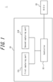
- the stereo camera system 1 includes an ECU (Electronic Control Unit) 20 and a stereo camera apparatus 30.
- the ECU 20 and the stereo camera apparatus 30 are connected to each other via a wired or wireless communication network and transmit/receive a variety of information.
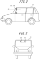
- the stereo camera apparatus 30 according to this embodiment is assumed to be mounted on a moving body 10 such as an automobile, for example. It is noted, however, that the stereo camera apparatus 30 can be mounted on a moving body 10 other than an automobile as well.
- the ECU 20 controls a device such as an engine, a brake, a steering (steering gear), a direction indicator or the like that is operated to run the moving body 10.
- the ECU 20 obtains the driving information indicating the driving conditions such as a speed, an acceleration rate, brake operation, a steering rudder angle, a direction indicated by a direction indicator, a headlight illumination range or the like from the above mentioned device. Further, the ECU 20 outputs the driving information to the stereo camera apparatus 30.
- the direction information among the driving information, the steering rudder angle and the direction indicated by a direction indicator are referred to as the direction information.
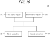
- the stereo camera apparatus 30 includes a stereo camera comprising at least two capturing parts such as a first capturing part 31L and a second capturing part 31R and a controller 33 (a first controller).
- the first and second capturing parts 31L and 31R comprise, for example, the same optical system and the same image sensor such as CMOS, CCD or the like, and an image formed by the optical system is captured by an image sensor.
- the angle of view of optical system may be wide.
- the first and second capturing parts 31L and 31R capture one frame image every predetermined time, such as every 0.1 second, for example.
- the first and second capturing parts 31L and 31R are mounted so that the optical axis OX of the optical system in the first and second capturing parts 31L and 31R will be in parallel with the forward direction so as to capture a front view of the moving body 10, for example.
- image sensors installed respectively in the first capturing part 31L and the second capturing part 31R are disposed so that they are located in the same plane vertical to the optical axis of the capturing parts and a line passing through reference points such as each center of the image sensors will be horizontal.
- the controller 33 is realized by an image processing microprocessor (Micro Processing Unit: MPU).
- MPU Micro Processing Unit
- the controller 33 obtains an image as the image information from the first and second capturing parts 31L and 31R via an image input/output interface (Interface I/F).
- the controller 33 also obtains the driving information of the moving body 10 from the ECU 20 via the CAN input/output interface.
- the controller 33 detects distance from the reference point of the stereo camera apparatus 30 to the object captured in an image based on the image captured by the first and second capturing parts 31L and 31R and the driving information.
- the reference point is any point that can be a reference for detecting distance for a stereo camera, and can be a middle point between each image sensor of the first and second capturing parts 31L and 31R, for example.
- the controller 33 detects distance by using a distance detection method for an object located near the moving body 10 (a near object) and a distance detection method for an object located far away from the moving body 10 (a distant object) depending on a plurality of regions in the image.
- the region is a region that constitutes a part of whole region of an image.
- the controller 33 positions a plurality of regions at different positions in a predetermined direction in an image.
- the predetermined direction is a direction substantially corresponding to a vertically upward direction in a captured image when the stereo camera apparatus 30 is mounted on the moving body 10. Further, among the plurality of regions, toward a predetermined direction, a region becomes smaller and an object located further away is captured.
- a plurality of regions are specified as a first region F and a second region N, and the first region F is located further toward the predetermined direction than the second region N.
- each first and second region F and N in the direction corresponding to the vertical direction may be determined previously, or may be determined based on the traveling speed of the moving body 10.
- respective positions of the first and second regions F and N are determined so that they are located further toward a predetermined direction as the moving body 10 travels faster, for example.
- the controller 33 determines respective positions of the first and second regions F and N with respect to the direction corresponding to the horizontal direction in the image based on the traveling direction of the moving body 10.
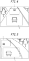
- a method of determining respective positions of the first and second regions F and N in the direction corresponding to the horizontal direction will be described in detail with reference to FIGS. 4 and 5.
- FIG. 4 is a view illustrating an example of an image captured by the first capturing part 31L when the moving body 10 travels straight ahead.
- FIG. 5 is a view illustrating an example of an image captured by the first capturing part 31L when the moving body 10 travels to the left.
- the controller 33 determines respective positions of the first and second regions F and N so that they are located in the central part in the horizontal direction in the image when the moving body 10 travels straight ahead. As illustrated in FIG. 5 , when the moving body 10 travels to the left, the respective positions of the first and second regions F and N are determined so that they are located on the left side of the central part in the horizontal direction in the image. Further, the first and second regions F and N may be determined based on the size of the rudder angle of the moving body 10.
- the first and second regions F and N are determined so that they are located more leftward, respectively, compared to the case where the moving body 10 travels 10 degrees to the left relative to the straight traveling direction.
- the image may include a plurality of the first and second regions F and N respectively.
- the controller 33 crops the second region N, which is a region for detecting a near object, from the first image and the second image captured respectively by the first and second capturing parts 31L and 31R. After cropping, the controller 33 performs stereo matching using the cropped images and detects distance.
- the controller 33 Based on original pixels of an image of an object captured in the first and second images, the controller 33 detects distance from a reference position to the object. In order to detect distance to the position of the detected object, stereo matching such as Semi Global Matching (SGM), etc. that uses SAD (Sum of Absolute Difference) function may be used.
- SGM Semi Global Matching
- SAD Sud of Absolute Difference
- the controller 33 crops the first region F, which is a region for detecting a distant object, from the first image. After cropping, the controller 33 performs object detection. Next, the controller 33 uses at least original pixels that constitute an image of the detected object and performs pixel interpolation with respect to original pixels in a region that is a little larger than a drawing region of the image of the object, for example. After performing pixel interpolation, the controller 33 performs pixel interpolation based on, in the second image captured at the same time, original pixels in the region corresponding to a drawing region of the object detected in the first region of the first image. Then the controller detects distance based on at least interpolation pixels generated by pixel interpolation of the first and second images.
- the controller 33 detects a predetermined target object to be detected such as a person, a vehicle or the like by using HOG (Histogram of Oriented Gradients) feature amount only with respect to the first region F in the image captured by the first capturing part 31L. More specifically, the controller 33 calculates the luminance gradient of pixels that constitute the first region F, and detects an object based on the calculated luminance gradient and the learning data of SVM (Support Vector Machine).
- HOG Heistogram of Oriented Gradients
- the controller 33 generates interpolation pixels based on original pixels in a region that is a little larger than a drawing region of an image of a detected object in an image of the same frame of the first image captured every predetermined time interval.
- the controller 33 weights each luminance value of two or more adjacent original pixels and computes using the linear interpolation method, for example, thereby calculating the luminance value at the central position among respective centers of the original pixels to generate interpolation pixels each having the calculated luminance value.
- the controller 33 may perform pixel interpolation by using not only the linear interpolation method, but also the Nearest Neighbor Method, the Bicubic method, the Lanczos algorithm or the like.
- an automobile is captured nearly in the center of the first region of the first image.
- the automobile is supposed to be captured on the left side of the center in the first region of the second image.
- the region A located on the left side of the region located at the same position as the drawing region of the first image is determined as a corresponding region.
- a wide region B that includes the region located at the same position as the region where an image of the object is detected in the first image may be determined as a corresponding region.
- the controller 33 detects distance from the reference position to the object based on at least interpolation pixels of the image of the object captured in the first and second images. That is, the controller 33 may detect distance based on both original pixels that constitute the image of the detected object and interpolation pixels, or based on only interpolation pixels. Except that stereo matching is performed with respect to the second region based on original pixels and stereo matching is performed with respect to the first region based on at least interpolation pixels, stereo matching and distance detection performed by the controller 33 with respect to the first region are the same as those performed with respect to the second region mentioned above.
- the distance from the reference point to the object detected in the above mentioned manner with respect to the first region and the second region is transmitted to the ECU 20 and is used to support operation of the moving body 10.
- each component of the stereo camera apparatus 30 can be realized by storing the program that describes the processing for realizing such function in the storage of the computer and by reading such program by the CPU of the computer to execute it.
- the first and second capturing parts 31L and 31R respectively capture an image of front of the moving body 10.
- the controller 33 obtains the image information representing the captured image from the first and second capturing parts 31L and 31R.
- the ECU 20 obtains the driving information, and the controller 33 obtains the driving information from the ECU 20.
- the controller 33 processes the image based on the driving information.
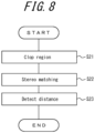
- the controller 33 crops the second region N from images respectively captured by the first and second capturing parts 31L and 31R based on the driving condition represented by the driving information (step S21).
- the controller 33 performs stereo matching based on original pixels that constitute the cropped second region N (step S22), and detects distance from the reference point to the object captured in the second region N (step S23).
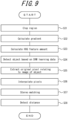
- the controller 33 crops the first region F from the first image based on the driving condition represented by the driving information (step S31). After the first region F is cropped in step S31, the controller 33 calculates the luminance gradient of pixels that constitute the first region F (step S32). Then, the controller 33 calculates HOG feature amount based on the gradient calculated in step S32 (step S33), and detects a target object to be detected based on the calculated HOG feature amount and the learning data of SVM (step S34).
- the controller 33 extracts original pixels in a region that is a little larger than a drawing region of the object in the first region of the first image detected in step S34.
- the controller 33 also extracts original pixels in the region of the second image corresponding to the drawing region of the first image where the image of the object is detected (step S35).
- the controller 33 performs pixel interpolation based on the original pixels extracted from the first and second images in step S35 to generate interpolation pixels (step S36).
- the controller 33 After interpolation pixels relating to the image of the detected object are generated with respect to the first and second images in step S36, the controller 33 performs stereo matching based on at least these interpolation pixels (step S37) and detects distance from the detected object to the reference position (step S38).
- the stereo camera apparatus 30 with respect to an object located far away from the stereo camera apparatus 30 and thus appearing small in an image, its distance is detected based on at least interpolation pixels, and as a result, distance can be detected based on a larger number of pixels compared to those in the case where pixel interpolation is not performed. Therefore distance can be detected with a high accuracy. Further, since pixel interpolation is performed only with respect to an image relating to the detected object while such distance detection with a high accuracy is realized, processing amount relating to pixel interpolation can be reduced compared to the case where pixel interpolation is performed with respect to all regions in the image.
- a region becomes smaller toward a predetermined direction, which allows for reduction in the processing amount relating to object detection and shortening of time required for processing.
- a region located further toward the predetermined direction is used to detect distance to an object located further away from the stereo camera apparatus 30, and an object located far away appears small in an image. Therefore, even if object detection is performed with respect to a small region, a target object to be detected can be detected.
- processing speed is increased compared to the case where pixel interpolation is performed by using an image containing different frames captured by the first capturing part 31L, such as, for example, an image of one frame and an image of the next frame.
- an image of one frame is subjected to pixel interpolation together with an image of the next frame, and therefore the controller should wait to start the processing until an image of the next frame is captured. Therefore, pixel interpolation which can be performed in real time based on pixels that constitute an image of the same frame is suitable for object detection by the stereo camera apparatus 30 mounted on the moving body 10 traveling at a high speed.
- distance detection can be performed with respect to a region that can be travelled by the moving body 10.
- the stereo camera apparatus 30 may include a stereo camera comprising the first and second capturing parts 31L and 31R, a first controller 33 and a second controller 34.
- the first controller 33 detects distance using the distance detection method for long distance
- the second controller 34 detects distance using the distance detection method for short distance.
- a plurality of controllers perform processing to different regions, respectively, which allows for reduction in the processing amount of each controller, and as a result, the stereo camera apparatus 30 can perform overall processing at a high speed.
- the first and second capturing parts 31L and 31R are mounted on a position where a front view of the moving body 10 is captured, they can be mounted on a position where a side or back view of the moving body 10 is captured.
- the stereo camera apparatus 30 can detect an object located far away on the side or back of the moving body 10 with a high accuracy and at a high processing speed.
- first and second regions F and N are illustrated as rectangular in shape, the shape of these regions is not limited to rectangular.
- the size and the shape of a region in an image may be determined based on the driving condition.
- the size of the region may be determined based on the speed of the moving body 10 and the shape of the region may be determined based on the illumination range or the rudder angle of the headlight.
- the controller 33 may transmit the information on the detected object and the measured size to other apparatuses or systems over the communication network.
Landscapes
- Engineering & Computer Science (AREA)
- Physics & Mathematics (AREA)
- General Physics & Mathematics (AREA)
- Theoretical Computer Science (AREA)
- Multimedia (AREA)
- Computer Vision & Pattern Recognition (AREA)
- Signal Processing (AREA)
- Remote Sensing (AREA)
- Radar, Positioning & Navigation (AREA)
- Electromagnetism (AREA)
- Measurement Of Optical Distance (AREA)
- Image Analysis (AREA)
- Image Processing (AREA)
Claims (12)
- Appareil de caméra stéréo (30), comprenant :une caméra stéréo comprenant une première partie de capture (31L) et une seconde partie de capture (31R) ; etun premier dispositif de commande (33) configuré pour :détecter un objet cible d'après au moins une première région (F) parmi une pluralité de régions situées à des positions différentes dans une direction prédéterminée sur une première image capturée par la première partie de capture (31L) de la caméra stéréo après rognage de la première région (F) à partir de la première image,générer des pixels d'interpolation par réalisation d'une interpolation de pixels d'après des pixels d'origine qui constituent une image de l'objet détecté sur la première image,et détecter une distance entre une position de référence et une position de l'objet détecté d'après au moins les pixels d'interpolation au moyen d'une mise en concordance stéréo,dans lequel la réalisation de l'interpolation de pixels comporte :l'extraction de pixels d'origine dans une région de la première image dans la première région (F) de la première image, dans lequel la région de la première image comporte une région de dessin de l'objet détecté ;l'extraction de pixels d'origine dans une région d'une seconde image capturée par la seconde partie de capture (31R) qui correspond à la région de dessin de l'objet détecté sur la première image, dans lequel la région de la seconde image comporte une région située à la même position que la région de dessin de l'objet détecté sur la première image,la réalisation d'une interpolation de pixels vis-à-vis des pixels d'origine extraits dans la région de la première image, etla réalisation d'une interpolation de pixels d'après, dans la seconde image capturée au même moment, des pixels d'origine dans la région correspondant à la région de dessin de l'objet détecté dans la première région (F) de la première image ;et en ce que la distance entre la position de référence et la position de l'objet détecté est détectée d'après au moins les pixels d'interpolation de l'image de l'objet capturée sur les première et seconde images au moyen d'une mise en concordance stéréo.
- Appareil de caméra stéréo (30) selon la revendication 1, dans lequel, parmi la pluralité de régions, une région devient plus petite à mesure qu'elle est située vers la direction prédéterminée.
- Appareil de caméra stéréo (30) selon la revendication 2, dans lequel, parmi la pluralité de régions, une région située plus loin vers la direction prédéterminée est utilisée pour détecter une distance jusqu'à un objet situé plus loin de l'appareil de caméra stéréo (30).
- Appareil de caméra stéréo (30) selon l'une quelconque des revendications 1 à 3, dans lequel la direction prédéterminée correspond sensiblement à une direction correspondant à verticalement vers le haut sur une image capturée par la caméra stéréo.
- Appareil de caméra stéréo (30) selon l'une quelconque des revendications 1 à 4, dans lequel l'interpolation de pixels est une interpolation de pixels qui utilise les pixels d'origine qui constituent une image d'une même trame capturée par la caméra stéréo.
- Appareil de caméra stéréo (30) selon l'une quelconque des revendications 1 à 5, dans lequel, dans une seconde région (N) différente de la première région de la pluralité de régions, une distance entre la position de référence et un objet dessiné dans la seconde région (N) est détectée d'après des pixels d'origine qui constituent la seconde région (N).
- Appareil de caméra stéréo (30) selon la revendication 6, dans lequel le premier dispositif de commande (33) détecte une distance entre la position de référence et l'objet dessiné dans la seconde région (N).
- Appareil de caméra stéréo (30) selon la revendication 6, comprenant en outre un second dispositif de commande (34) configuré pour détecter une distance entre la position de référence et l'objet dessiné dans la seconde région (N).
- Appareil de caméra stéréo (30) selon l'une quelconque des revendications 1 à 8, dans lequel le premier dispositif de commande (33) détecte un objet d'après seulement une image capturée par l'une des deux parties de capture (31L, 31R).
- Appareil de caméra stéréo (30) selon l'une quelconque des revendications 1 à 9, dans lequel le premier dispositif de commande (33) détermine une ou plusieurs parmi une position, une taille et une forme d'au moins l'une de la pluralité de régions d'après une condition de conduite d'un véhicule comprenant la caméra stéréo.
- Véhicule (10) comprenant l'appareil de caméra stéréo (30) selon l'une quelconque des revendications 1 à 9.
- Véhicule (10) selon la revendication 11, dans lequel le premier dispositif de commande (33) de l'appareil de caméra stéréo (30) détermine une ou plusieurs parmi une position, une taille et une forme d'au moins une région de la pluralité de régions d'après la condition de conduite du véhicule (10) comprenant la caméra stéréo.
Applications Claiming Priority (2)
| Application Number | Priority Date | Filing Date | Title |
|---|---|---|---|
| JP2014217370 | 2014-10-24 | ||
| PCT/JP2015/005346 WO2016063545A1 (fr) | 2014-10-24 | 2015-10-23 | Appareil de caméra stéréo et véhicule comprenant un appareil de caméra stéréo |
Publications (3)
| Publication Number | Publication Date |
|---|---|
| EP3211368A1 EP3211368A1 (fr) | 2017-08-30 |
| EP3211368A4 EP3211368A4 (fr) | 2018-06-06 |
| EP3211368B1 true EP3211368B1 (fr) | 2023-07-26 |
Family
ID=55760603
Family Applications (1)
| Application Number | Title | Priority Date | Filing Date |
|---|---|---|---|
| EP15852427.2A Active EP3211368B1 (fr) | 2014-10-24 | 2015-10-23 | Appareil de caméra stéréo et véhicule comprenant un appareil de caméra stéréo |
Country Status (4)
| Country | Link |
|---|---|
| US (1) | US10595003B2 (fr) |
| EP (1) | EP3211368B1 (fr) |
| JP (1) | JP6306735B2 (fr) |
| WO (1) | WO2016063545A1 (fr) |
Families Citing this family (7)
| Publication number | Priority date | Publication date | Assignee | Title |
|---|---|---|---|---|
| JP6660751B2 (ja) * | 2016-02-04 | 2020-03-11 | 日立オートモティブシステムズ株式会社 | 撮像装置 |
| DE112017006840B4 (de) * | 2017-01-16 | 2023-11-02 | Fujitsu Limited | Informationsverarbeitungsprogramm, Informationsverarbeitungsverfahren und Informationsverarbeitungsvorrichtung |
| US11435752B2 (en) | 2018-03-23 | 2022-09-06 | Motional Ad Llc | Data fusion system for a vehicle equipped with unsynchronized perception sensors |
| JP7121269B2 (ja) | 2018-07-06 | 2022-08-18 | ミツミ電機株式会社 | 測距カメラ |
| JP7256623B2 (ja) * | 2018-09-27 | 2023-04-12 | 株式会社Subaru | 車両用ステレオカメラ装置 |
| WO2021064511A1 (fr) * | 2019-10-04 | 2021-04-08 | 株式会社半導体エネルギー研究所 | Dispositif à semi-conducteurs et système de détermination |
| JP7554105B2 (ja) | 2020-12-02 | 2024-09-19 | ヤマハ発動機株式会社 | 距離認識システムおよびその制御方法、船舶 |
Family Cites Families (14)
| Publication number | Priority date | Publication date | Assignee | Title |
|---|---|---|---|---|
| JPH07225126A (ja) | 1994-02-14 | 1995-08-22 | Mitsubishi Motors Corp | 車両用路上物体認識装置 |
| JP3235393B2 (ja) * | 1995-03-17 | 2001-12-04 | トヨタ自動車株式会社 | 移動ベクトル抽出方法 |
| JP2001126065A (ja) * | 1999-10-26 | 2001-05-11 | Toyota Central Res & Dev Lab Inc | 距離分布検知装置 |
| JP2004061446A (ja) * | 2002-07-31 | 2004-02-26 | Fujitsu Ten Ltd | パターンマッチング処理方法及び画像処理装置 |
| JP4394487B2 (ja) | 2004-03-05 | 2010-01-06 | 富士重工業株式会社 | ステレオ画像処理装置 |
| JP2006317193A (ja) * | 2005-05-10 | 2006-11-24 | Olympus Corp | 画像処理装置、画像処理方法、および画像処理用プログラム |
| US7551771B2 (en) * | 2005-09-20 | 2009-06-23 | Deltasphere, Inc. | Methods, systems, and computer program products for acquiring three-dimensional range information |
| JP2008276308A (ja) * | 2007-04-25 | 2008-11-13 | Sanyo Electric Co Ltd | 動画像処理装置、動画像処理システムおよびナビゲーション装置 |
| JP2010079582A (ja) * | 2008-09-25 | 2010-04-08 | Toshiba Corp | 物体を検出する装置、方法及びプログラム |
| JP5468426B2 (ja) * | 2010-03-12 | 2014-04-09 | 日立オートモティブシステムズ株式会社 | ステレオカメラ装置 |
| JP2012252501A (ja) * | 2011-06-02 | 2012-12-20 | Toyota Central R&D Labs Inc | 走行路認識装置及び走行路認識用プログラム |
| DE112012003685T5 (de) * | 2011-09-05 | 2014-07-10 | Mitsubishi Electric Corp. | Bildverarbeitungsvorrichtung und Bildverarbeitungsverfahren |
| DE102013101639A1 (de) * | 2013-02-19 | 2014-09-04 | Continental Teves Ag & Co. Ohg | Verfahren und Vorrichtung zur Bestimmung eines Fahrbahnzustands |
| JP6550881B2 (ja) * | 2014-07-14 | 2019-07-31 | 株式会社リコー | 立体物検出装置、立体物検出方法、立体物検出プログラム、及び移動体機器制御システム |
-
2015
- 2015-10-23 JP JP2016555091A patent/JP6306735B2/ja active Active
- 2015-10-23 WO PCT/JP2015/005346 patent/WO2016063545A1/fr not_active Ceased
- 2015-10-23 EP EP15852427.2A patent/EP3211368B1/fr active Active
- 2015-10-23 US US15/520,760 patent/US10595003B2/en active Active
Also Published As
| Publication number | Publication date |
|---|---|
| EP3211368A1 (fr) | 2017-08-30 |
| WO2016063545A1 (fr) | 2016-04-28 |
| JPWO2016063545A1 (ja) | 2017-06-29 |
| JP6306735B2 (ja) | 2018-04-04 |
| EP3211368A4 (fr) | 2018-06-06 |
| US20170318279A1 (en) | 2017-11-02 |
| US10595003B2 (en) | 2020-03-17 |
Similar Documents
| Publication | Publication Date | Title |
|---|---|---|
| EP3211368B1 (fr) | Appareil de caméra stéréo et véhicule comprenant un appareil de caméra stéréo | |
| CN102422333B (zh) | 车辆周围监测装置 | |
| EP3400556B1 (fr) | Systèmes et procédés d'estimation de futures trajectoires | |
| JP5267596B2 (ja) | 移動体検出装置 | |
| EP2546602B1 (fr) | Dispositif d'appareil photographique stéréoscopique | |
| US9704047B2 (en) | Moving object recognition apparatus | |
| EP2571005B1 (fr) | Dispositif de surveillance des alentours d'un véhicule | |
| EP2642429A2 (fr) | Système d'appareil photo multi-objectifs et procédé de recherche de portée exécuté par le système d'appareil photo multi-objectifs | |
| EP3136368A1 (fr) | Appareil de reconnaissance d'environnement externe | |
| EP3422293B1 (fr) | Objet mobile | |
| CN103368527B (zh) | 用于传感器数据的滤波方法和滤波设备 | |
| WO2017134982A1 (fr) | Dispositif d'imagerie | |
| JP5937832B2 (ja) | 車載カメラ用露出制御装置 | |
| EP3176750B1 (fr) | Système de vision pour un véhicule automobile et procédé de commande dudit système | |
| US10354148B2 (en) | Object detection apparatus, vehicle provided with object detection apparatus, and non-transitory recording medium | |
| US10417507B2 (en) | Freespace detection apparatus and freespace detection method | |
| EP2778603B1 (fr) | Appareil de traitement d'image et procédé de traitement d'image | |
| EP3690812B1 (fr) | Dispositif de détection de distance d'objet | |
| JP6466679B2 (ja) | 物体検出装置 | |
| CN121488288A (zh) | 车载图像处理装置 | |
| JP2017072914A (ja) | 物体認識装置 | |
| EP3312797A1 (fr) | Système de vision et procédé pour véhicule à moteur |
Legal Events
| Date | Code | Title | Description |
|---|---|---|---|
| STAA | Information on the status of an ep patent application or granted ep patent |
Free format text: STATUS: THE INTERNATIONAL PUBLICATION HAS BEEN MADE |
|
| PUAI | Public reference made under article 153(3) epc to a published international application that has entered the european phase |
Free format text: ORIGINAL CODE: 0009012 |
|
| STAA | Information on the status of an ep patent application or granted ep patent |
Free format text: STATUS: REQUEST FOR EXAMINATION WAS MADE |
|
| 17P | Request for examination filed |
Effective date: 20170424 |
|
| AK | Designated contracting states |
Kind code of ref document: A1 Designated state(s): AL AT BE BG CH CY CZ DE DK EE ES FI FR GB GR HR HU IE IS IT LI LT LU LV MC MK MT NL NO PL PT RO RS SE SI SK SM TR |
|
| AX | Request for extension of the european patent |
Extension state: BA ME |
|
| DAV | Request for validation of the european patent (deleted) | ||
| DAX | Request for extension of the european patent (deleted) | ||
| RIC1 | Information provided on ipc code assigned before grant |
Ipc: H04N 13/00 20060101ALI20180426BHEP Ipc: G01C 3/06 20060101AFI20180426BHEP Ipc: H04N 5/232 20060101ALI20180426BHEP Ipc: B60R 21/00 20060101ALI20180426BHEP |
|
| A4 | Supplementary search report drawn up and despatched |
Effective date: 20180507 |
|
| STAA | Information on the status of an ep patent application or granted ep patent |
Free format text: STATUS: EXAMINATION IS IN PROGRESS |
|
| 17Q | First examination report despatched |
Effective date: 20200730 |
|
| RIC1 | Information provided on ipc code assigned before grant |
Ipc: H04N 13/00 20060101ALI20230113BHEP Ipc: B60R 21/00 20060101ALI20230113BHEP Ipc: G01C 3/06 20060101AFI20230113BHEP |
|
| GRAP | Despatch of communication of intention to grant a patent |
Free format text: ORIGINAL CODE: EPIDOSNIGR1 |
|
| STAA | Information on the status of an ep patent application or granted ep patent |
Free format text: STATUS: GRANT OF PATENT IS INTENDED |
|
| INTG | Intention to grant announced |
Effective date: 20230227 |
|
| P01 | Opt-out of the competence of the unified patent court (upc) registered |
Effective date: 20230505 |
|
| GRAS | Grant fee paid |
Free format text: ORIGINAL CODE: EPIDOSNIGR3 |
|
| GRAA | (expected) grant |
Free format text: ORIGINAL CODE: 0009210 |
|
| STAA | Information on the status of an ep patent application or granted ep patent |
Free format text: STATUS: THE PATENT HAS BEEN GRANTED |
|
| AK | Designated contracting states |
Kind code of ref document: B1 Designated state(s): AL AT BE BG CH CY CZ DE DK EE ES FI FR GB GR HR HU IE IS IT LI LT LU LV MC MK MT NL NO PL PT RO RS SE SI SK SM TR |
|
| REG | Reference to a national code |
Ref country code: GB Ref legal event code: FG4D |
|
| REG | Reference to a national code |
Ref country code: CH Ref legal event code: EP |
|
| REG | Reference to a national code |
Ref country code: IE Ref legal event code: FG4D |
|
| REG | Reference to a national code |
Ref country code: DE Ref legal event code: R096 Ref document number: 602015084818 Country of ref document: DE |
|
| PGFP | Annual fee paid to national office [announced via postgrant information from national office to epo] |
Ref country code: GB Payment date: 20230914 Year of fee payment: 9 |
|
| REG | Reference to a national code |
Ref country code: LT Ref legal event code: MG9D |
|
| REG | Reference to a national code |
Ref country code: NL Ref legal event code: MP Effective date: 20230726 |
|
| PGFP | Annual fee paid to national office [announced via postgrant information from national office to epo] |
Ref country code: FR Payment date: 20230921 Year of fee payment: 9 |
|
| REG | Reference to a national code |
Ref country code: AT Ref legal event code: MK05 Ref document number: 1592388 Country of ref document: AT Kind code of ref document: T Effective date: 20230726 |
|
| PG25 | Lapsed in a contracting state [announced via postgrant information from national office to epo] |
Ref country code: NL Free format text: LAPSE BECAUSE OF FAILURE TO SUBMIT A TRANSLATION OF THE DESCRIPTION OR TO PAY THE FEE WITHIN THE PRESCRIBED TIME-LIMIT Effective date: 20230726 |
|
| PG25 | Lapsed in a contracting state [announced via postgrant information from national office to epo] |
Ref country code: GR Free format text: LAPSE BECAUSE OF FAILURE TO SUBMIT A TRANSLATION OF THE DESCRIPTION OR TO PAY THE FEE WITHIN THE PRESCRIBED TIME-LIMIT Effective date: 20231027 |
|
| PG25 | Lapsed in a contracting state [announced via postgrant information from national office to epo] |
Ref country code: IS Free format text: LAPSE BECAUSE OF FAILURE TO SUBMIT A TRANSLATION OF THE DESCRIPTION OR TO PAY THE FEE WITHIN THE PRESCRIBED TIME-LIMIT Effective date: 20231126 |
|
| PG25 | Lapsed in a contracting state [announced via postgrant information from national office to epo] |
Ref country code: SE Free format text: LAPSE BECAUSE OF FAILURE TO SUBMIT A TRANSLATION OF THE DESCRIPTION OR TO PAY THE FEE WITHIN THE PRESCRIBED TIME-LIMIT Effective date: 20230726 Ref country code: RS Free format text: LAPSE BECAUSE OF FAILURE TO SUBMIT A TRANSLATION OF THE DESCRIPTION OR TO PAY THE FEE WITHIN THE PRESCRIBED TIME-LIMIT Effective date: 20230726 Ref country code: PT Free format text: LAPSE BECAUSE OF FAILURE TO SUBMIT A TRANSLATION OF THE DESCRIPTION OR TO PAY THE FEE WITHIN THE PRESCRIBED TIME-LIMIT Effective date: 20231127 Ref country code: NO Free format text: LAPSE BECAUSE OF FAILURE TO SUBMIT A TRANSLATION OF THE DESCRIPTION OR TO PAY THE FEE WITHIN THE PRESCRIBED TIME-LIMIT Effective date: 20231026 Ref country code: LV Free format text: LAPSE BECAUSE OF FAILURE TO SUBMIT A TRANSLATION OF THE DESCRIPTION OR TO PAY THE FEE WITHIN THE PRESCRIBED TIME-LIMIT Effective date: 20230726 Ref country code: LT Free format text: LAPSE BECAUSE OF FAILURE TO SUBMIT A TRANSLATION OF THE DESCRIPTION OR TO PAY THE FEE WITHIN THE PRESCRIBED TIME-LIMIT Effective date: 20230726 Ref country code: IS Free format text: LAPSE BECAUSE OF FAILURE TO SUBMIT A TRANSLATION OF THE DESCRIPTION OR TO PAY THE FEE WITHIN THE PRESCRIBED TIME-LIMIT Effective date: 20231126 Ref country code: HR Free format text: LAPSE BECAUSE OF FAILURE TO SUBMIT A TRANSLATION OF THE DESCRIPTION OR TO PAY THE FEE WITHIN THE PRESCRIBED TIME-LIMIT Effective date: 20230726 Ref country code: GR Free format text: LAPSE BECAUSE OF FAILURE TO SUBMIT A TRANSLATION OF THE DESCRIPTION OR TO PAY THE FEE WITHIN THE PRESCRIBED TIME-LIMIT Effective date: 20231027 Ref country code: FI Free format text: LAPSE BECAUSE OF FAILURE TO SUBMIT A TRANSLATION OF THE DESCRIPTION OR TO PAY THE FEE WITHIN THE PRESCRIBED TIME-LIMIT Effective date: 20230726 Ref country code: AT Free format text: LAPSE BECAUSE OF FAILURE TO SUBMIT A TRANSLATION OF THE DESCRIPTION OR TO PAY THE FEE WITHIN THE PRESCRIBED TIME-LIMIT Effective date: 20230726 |
|
| PGFP | Annual fee paid to national office [announced via postgrant information from national office to epo] |
Ref country code: DE Payment date: 20230912 Year of fee payment: 9 |
|
| PG25 | Lapsed in a contracting state [announced via postgrant information from national office to epo] |
Ref country code: PL Free format text: LAPSE BECAUSE OF FAILURE TO SUBMIT A TRANSLATION OF THE DESCRIPTION OR TO PAY THE FEE WITHIN THE PRESCRIBED TIME-LIMIT Effective date: 20230726 |
|
| PG25 | Lapsed in a contracting state [announced via postgrant information from national office to epo] |
Ref country code: ES Free format text: LAPSE BECAUSE OF FAILURE TO SUBMIT A TRANSLATION OF THE DESCRIPTION OR TO PAY THE FEE WITHIN THE PRESCRIBED TIME-LIMIT Effective date: 20230726 |
|
| REG | Reference to a national code |
Ref country code: DE Ref legal event code: R097 Ref document number: 602015084818 Country of ref document: DE |
|
| PG25 | Lapsed in a contracting state [announced via postgrant information from national office to epo] |
Ref country code: SM Free format text: LAPSE BECAUSE OF FAILURE TO SUBMIT A TRANSLATION OF THE DESCRIPTION OR TO PAY THE FEE WITHIN THE PRESCRIBED TIME-LIMIT Effective date: 20230726 Ref country code: RO Free format text: LAPSE BECAUSE OF FAILURE TO SUBMIT A TRANSLATION OF THE DESCRIPTION OR TO PAY THE FEE WITHIN THE PRESCRIBED TIME-LIMIT Effective date: 20230726 Ref country code: ES Free format text: LAPSE BECAUSE OF FAILURE TO SUBMIT A TRANSLATION OF THE DESCRIPTION OR TO PAY THE FEE WITHIN THE PRESCRIBED TIME-LIMIT Effective date: 20230726 Ref country code: EE Free format text: LAPSE BECAUSE OF FAILURE TO SUBMIT A TRANSLATION OF THE DESCRIPTION OR TO PAY THE FEE WITHIN THE PRESCRIBED TIME-LIMIT Effective date: 20230726 Ref country code: DK Free format text: LAPSE BECAUSE OF FAILURE TO SUBMIT A TRANSLATION OF THE DESCRIPTION OR TO PAY THE FEE WITHIN THE PRESCRIBED TIME-LIMIT Effective date: 20230726 Ref country code: CZ Free format text: LAPSE BECAUSE OF FAILURE TO SUBMIT A TRANSLATION OF THE DESCRIPTION OR TO PAY THE FEE WITHIN THE PRESCRIBED TIME-LIMIT Effective date: 20230726 Ref country code: SK Free format text: LAPSE BECAUSE OF FAILURE TO SUBMIT A TRANSLATION OF THE DESCRIPTION OR TO PAY THE FEE WITHIN THE PRESCRIBED TIME-LIMIT Effective date: 20230726 |
|
| PG25 | Lapsed in a contracting state [announced via postgrant information from national office to epo] |
Ref country code: IT Free format text: LAPSE BECAUSE OF FAILURE TO SUBMIT A TRANSLATION OF THE DESCRIPTION OR TO PAY THE FEE WITHIN THE PRESCRIBED TIME-LIMIT Effective date: 20230726 Ref country code: MC Free format text: LAPSE BECAUSE OF FAILURE TO SUBMIT A TRANSLATION OF THE DESCRIPTION OR TO PAY THE FEE WITHIN THE PRESCRIBED TIME-LIMIT Effective date: 20230726 |
|
| PLBE | No opposition filed within time limit |
Free format text: ORIGINAL CODE: 0009261 |
|
| REG | Reference to a national code |
Ref country code: CH Ref legal event code: PL |
|
| STAA | Information on the status of an ep patent application or granted ep patent |
Free format text: STATUS: NO OPPOSITION FILED WITHIN TIME LIMIT |
|
| REG | Reference to a national code |
Ref country code: BE Ref legal event code: MM Effective date: 20231031 |
|
| PG25 | Lapsed in a contracting state [announced via postgrant information from national office to epo] |
Ref country code: LU Free format text: LAPSE BECAUSE OF NON-PAYMENT OF DUE FEES Effective date: 20231023 |
|
| PG25 | Lapsed in a contracting state [announced via postgrant information from national office to epo] |
Ref country code: LU Free format text: LAPSE BECAUSE OF NON-PAYMENT OF DUE FEES Effective date: 20231023 |
|
| 26N | No opposition filed |
Effective date: 20240429 |
|
| PG25 | Lapsed in a contracting state [announced via postgrant information from national office to epo] |
Ref country code: CH Free format text: LAPSE BECAUSE OF NON-PAYMENT OF DUE FEES Effective date: 20231031 |
|
| PG25 | Lapsed in a contracting state [announced via postgrant information from national office to epo] |
Ref country code: CH Free format text: LAPSE BECAUSE OF NON-PAYMENT OF DUE FEES Effective date: 20231031 Ref country code: SI Free format text: LAPSE BECAUSE OF FAILURE TO SUBMIT A TRANSLATION OF THE DESCRIPTION OR TO PAY THE FEE WITHIN THE PRESCRIBED TIME-LIMIT Effective date: 20230726 |
|
| PG25 | Lapsed in a contracting state [announced via postgrant information from national office to epo] |
Ref country code: BE Free format text: LAPSE BECAUSE OF NON-PAYMENT OF DUE FEES Effective date: 20231031 |
|
| PG25 | Lapsed in a contracting state [announced via postgrant information from national office to epo] |
Ref country code: IE Free format text: LAPSE BECAUSE OF NON-PAYMENT OF DUE FEES Effective date: 20231023 |
|
| PG25 | Lapsed in a contracting state [announced via postgrant information from national office to epo] |
Ref country code: IE Free format text: LAPSE BECAUSE OF NON-PAYMENT OF DUE FEES Effective date: 20231023 |
|
| PG25 | Lapsed in a contracting state [announced via postgrant information from national office to epo] |
Ref country code: BG Free format text: LAPSE BECAUSE OF FAILURE TO SUBMIT A TRANSLATION OF THE DESCRIPTION OR TO PAY THE FEE WITHIN THE PRESCRIBED TIME-LIMIT Effective date: 20230726 |
|
| PG25 | Lapsed in a contracting state [announced via postgrant information from national office to epo] |
Ref country code: BG Free format text: LAPSE BECAUSE OF FAILURE TO SUBMIT A TRANSLATION OF THE DESCRIPTION OR TO PAY THE FEE WITHIN THE PRESCRIBED TIME-LIMIT Effective date: 20230726 |
|
| REG | Reference to a national code |
Ref country code: DE Ref legal event code: R119 Ref document number: 602015084818 Country of ref document: DE |
|
| GBPC | Gb: european patent ceased through non-payment of renewal fee |
Effective date: 20241023 |
|
| PG25 | Lapsed in a contracting state [announced via postgrant information from national office to epo] |
Ref country code: DE Free format text: LAPSE BECAUSE OF NON-PAYMENT OF DUE FEES Effective date: 20250501 |
|
| PG25 | Lapsed in a contracting state [announced via postgrant information from national office to epo] |
Ref country code: GB Free format text: LAPSE BECAUSE OF NON-PAYMENT OF DUE FEES Effective date: 20241023 |
|
| PG25 | Lapsed in a contracting state [announced via postgrant information from national office to epo] |
Ref country code: FR Free format text: LAPSE BECAUSE OF NON-PAYMENT OF DUE FEES Effective date: 20241031 |
|
| PG25 | Lapsed in a contracting state [announced via postgrant information from national office to epo] |
Ref country code: CY Free format text: LAPSE BECAUSE OF FAILURE TO SUBMIT A TRANSLATION OF THE DESCRIPTION OR TO PAY THE FEE WITHIN THE PRESCRIBED TIME-LIMIT; INVALID AB INITIO Effective date: 20151023 |
|
| PG25 | Lapsed in a contracting state [announced via postgrant information from national office to epo] |
Ref country code: HU Free format text: LAPSE BECAUSE OF FAILURE TO SUBMIT A TRANSLATION OF THE DESCRIPTION OR TO PAY THE FEE WITHIN THE PRESCRIBED TIME-LIMIT; INVALID AB INITIO Effective date: 20151023 |
|
| PG25 | Lapsed in a contracting state [announced via postgrant information from national office to epo] |
Ref country code: TR Free format text: LAPSE BECAUSE OF FAILURE TO SUBMIT A TRANSLATION OF THE DESCRIPTION OR TO PAY THE FEE WITHIN THE PRESCRIBED TIME-LIMIT Effective date: 20230726 |