EP3209596B1 - Wear pad for telescoping boom - Google Patents
Wear pad for telescoping boom Download PDFInfo
- Publication number
- EP3209596B1 EP3209596B1 EP15851716.9A EP15851716A EP3209596B1 EP 3209596 B1 EP3209596 B1 EP 3209596B1 EP 15851716 A EP15851716 A EP 15851716A EP 3209596 B1 EP3209596 B1 EP 3209596B1
- Authority
- EP
- European Patent Office
- Prior art keywords
- wear pad
- base
- pad assembly
- assembly
- wear
- Prior art date
- Legal status (The legal status is an assumption and is not a legal conclusion. Google has not performed a legal analysis and makes no representation as to the accuracy of the status listed.)
- Active
Links
Images


Classifications
-
- B—PERFORMING OPERATIONS; TRANSPORTING
- B66—HOISTING; LIFTING; HAULING
- B66C—CRANES; LOAD-ENGAGING ELEMENTS OR DEVICES FOR CRANES, CAPSTANS, WINCHES, OR TACKLES
- B66C23/00—Cranes comprising essentially a beam, boom, or triangular structure acting as a cantilever and mounted for translatory of swinging movements in vertical or horizontal planes or a combination of such movements, e.g. jib-cranes, derricks, tower cranes
- B66C23/62—Constructional features or details
- B66C23/64—Jibs
- B66C23/70—Jibs constructed of sections adapted to be assembled to form jibs or various lengths
- B66C23/701—Jibs constructed of sections adapted to be assembled to form jibs or various lengths telescopic
- B66C23/707—Jibs constructed of sections adapted to be assembled to form jibs or various lengths telescopic guiding devices for telescopic jibs
-
- F—MECHANICAL ENGINEERING; LIGHTING; HEATING; WEAPONS; BLASTING
- F16—ENGINEERING ELEMENTS AND UNITS; GENERAL MEASURES FOR PRODUCING AND MAINTAINING EFFECTIVE FUNCTIONING OF MACHINES OR INSTALLATIONS; THERMAL INSULATION IN GENERAL
- F16B—DEVICES FOR FASTENING OR SECURING CONSTRUCTIONAL ELEMENTS OR MACHINE PARTS TOGETHER, e.g. NAILS, BOLTS, CIRCLIPS, CLAMPS, CLIPS OR WEDGES; JOINTS OR JOINTING
- F16B39/00—Locking of screws, bolts or nuts
- F16B39/02—Locking of screws, bolts or nuts in which the locking takes place after screwing down
- F16B39/028—Locking of screws, bolts or nuts in which the locking takes place after screwing down by means of an auxiliary bolt or threaded element whose action provokes the deformation of the main bolt or nut and thereby its blocking
-
- F—MECHANICAL ENGINEERING; LIGHTING; HEATING; WEAPONS; BLASTING
- F16—ENGINEERING ELEMENTS AND UNITS; GENERAL MEASURES FOR PRODUCING AND MAINTAINING EFFECTIVE FUNCTIONING OF MACHINES OR INSTALLATIONS; THERMAL INSULATION IN GENERAL
- F16C—SHAFTS; FLEXIBLE SHAFTS; ELEMENTS OR CRANKSHAFT MECHANISMS; ROTARY BODIES OTHER THAN GEARING ELEMENTS; BEARINGS
- F16C29/00—Bearings for parts moving only linearly
- F16C29/02—Sliding-contact bearings
-
- F—MECHANICAL ENGINEERING; LIGHTING; HEATING; WEAPONS; BLASTING
- F16—ENGINEERING ELEMENTS AND UNITS; GENERAL MEASURES FOR PRODUCING AND MAINTAINING EFFECTIVE FUNCTIONING OF MACHINES OR INSTALLATIONS; THERMAL INSULATION IN GENERAL
- F16C—SHAFTS; FLEXIBLE SHAFTS; ELEMENTS OR CRANKSHAFT MECHANISMS; ROTARY BODIES OTHER THAN GEARING ELEMENTS; BEARINGS
- F16C29/00—Bearings for parts moving only linearly
- F16C29/12—Arrangements for adjusting play
-
- F—MECHANICAL ENGINEERING; LIGHTING; HEATING; WEAPONS; BLASTING
- F16—ENGINEERING ELEMENTS AND UNITS; GENERAL MEASURES FOR PRODUCING AND MAINTAINING EFFECTIVE FUNCTIONING OF MACHINES OR INSTALLATIONS; THERMAL INSULATION IN GENERAL
- F16C—SHAFTS; FLEXIBLE SHAFTS; ELEMENTS OR CRANKSHAFT MECHANISMS; ROTARY BODIES OTHER THAN GEARING ELEMENTS; BEARINGS
- F16C33/00—Parts of bearings; Special methods for making bearings or parts thereof
- F16C33/02—Parts of sliding-contact bearings
- F16C33/04—Brasses; Bushes; Linings
- F16C33/06—Sliding surface mainly made of metal
- F16C33/12—Structural composition; Use of special materials or surface treatments, e.g. for rust-proofing
-
- F—MECHANICAL ENGINEERING; LIGHTING; HEATING; WEAPONS; BLASTING
- F16—ENGINEERING ELEMENTS AND UNITS; GENERAL MEASURES FOR PRODUCING AND MAINTAINING EFFECTIVE FUNCTIONING OF MACHINES OR INSTALLATIONS; THERMAL INSULATION IN GENERAL
- F16C—SHAFTS; FLEXIBLE SHAFTS; ELEMENTS OR CRANKSHAFT MECHANISMS; ROTARY BODIES OTHER THAN GEARING ELEMENTS; BEARINGS
- F16C33/00—Parts of bearings; Special methods for making bearings or parts thereof
- F16C33/02—Parts of sliding-contact bearings
- F16C33/04—Brasses; Bushes; Linings
- F16C33/26—Brasses; Bushes; Linings made from wire coils; made from a number of discs, rings, rods, or other members
-
- F—MECHANICAL ENGINEERING; LIGHTING; HEATING; WEAPONS; BLASTING
- F16—ENGINEERING ELEMENTS AND UNITS; GENERAL MEASURES FOR PRODUCING AND MAINTAINING EFFECTIVE FUNCTIONING OF MACHINES OR INSTALLATIONS; THERMAL INSULATION IN GENERAL
- F16C—SHAFTS; FLEXIBLE SHAFTS; ELEMENTS OR CRANKSHAFT MECHANISMS; ROTARY BODIES OTHER THAN GEARING ELEMENTS; BEARINGS
- F16C35/00—Rigid support of bearing units; Housings, e.g. caps, covers
- F16C35/02—Rigid support of bearing units; Housings, e.g. caps, covers in the case of sliding-contact bearings
-
- F—MECHANICAL ENGINEERING; LIGHTING; HEATING; WEAPONS; BLASTING
- F16—ENGINEERING ELEMENTS AND UNITS; GENERAL MEASURES FOR PRODUCING AND MAINTAINING EFFECTIVE FUNCTIONING OF MACHINES OR INSTALLATIONS; THERMAL INSULATION IN GENERAL
- F16C—SHAFTS; FLEXIBLE SHAFTS; ELEMENTS OR CRANKSHAFT MECHANISMS; ROTARY BODIES OTHER THAN GEARING ELEMENTS; BEARINGS
- F16C43/00—Assembling bearings
- F16C43/02—Assembling sliding-contact bearings
-
- F—MECHANICAL ENGINEERING; LIGHTING; HEATING; WEAPONS; BLASTING
- F16—ENGINEERING ELEMENTS AND UNITS; GENERAL MEASURES FOR PRODUCING AND MAINTAINING EFFECTIVE FUNCTIONING OF MACHINES OR INSTALLATIONS; THERMAL INSULATION IN GENERAL
- F16C—SHAFTS; FLEXIBLE SHAFTS; ELEMENTS OR CRANKSHAFT MECHANISMS; ROTARY BODIES OTHER THAN GEARING ELEMENTS; BEARINGS
- F16C2326/00—Articles relating to transporting
Definitions
- the present disclosure relates to a wear button or pad for a telescoping boom, and to a telescoping boom comprising the same.
- Telescoping booms are employed in machines as varied as cranes, excavators, concrete pumps, elevated work platforms and drill rigs.
- a typical telescopic boom assembly comprises telescoping boxlike boom sections and several adjustable wear buttons working against each sliding surface of the boom sections to smoothly guide the moving boom sections through extension and retraction.
- the wear buttons are adjustable to compensate for wear thereof, which would otherwise permit free play, or slop between the boom sections.
- a typical wear button comprises steel backing and adjuster parts for a bronze wear button.
- the steel backing piece comprises a male thread which screws into a female thread of the steel adjuster housing part of the boom, so that the wear button can be adjusted.
- There is generally a locking cover which is also screwed into the adjuster housing female thread to lock against the steel adjuster and prevent movement.
- the adjuster In typical applications the adjuster is required to handle up to 100 tons of load, and can be subject to repetitive shock load.
- the adjusters and locking plates of previous wear buttons work loose after a short period of service, so they then can unwind and/or begin to wear both the adjuster's male thread, and the boom's female thread, making the adjuster inherently subject to jamming, cross threading, or the adjuster being ejected from the boom.
- a partially ejected or cross threaded adjuster is extremely difficult to remove once failed.
- EP 2 789 770 A1 discloses the preamble of claim 1.
- DE 27 49 332 A1 discloses a wear pad for a telescoping boom.
- the present invention is as defined by the appended claims and is a wear pad assembly for use with a boom assembly comprising at least an outer boom member comprising a threaded bore therethrough for the wear pad assembly, and an inner boom member that is slidable with respect to the outer boom member, the wear pad assembly comprising a wear pad and a base, a first of which comprises a generally cylindrical body comprising a curved external side surface comprising a screw thread via which this is threadably engageable in the threaded bore, and an internally tapered expandable collet, and the second of which comprises an externally and complementarily tapered mandrel portion, wherein in use, the externally threaded part is threadably engaged in the threaded bore and expanded therein by insertion of the externally and complementarily tapered mandrel portion in the expandable collet.
- the base comprises the external side surface comprising the screw thread, and the internally tapered expandable collet, and the wear pad comprises the externally and complementarily tapered mandrel portion.
- the wear pad comprises the curved external side surface comprising the screw thread, and the internally tapered expandable collet, and the base comprises the externally and complementarily tapered mandrel portion.
- the wear pad assembly further comprises at least one fastener for securing the base and the wear pad together.
- the or each fastener is a working bolt.
- the wear pad comprises a threaded bolt hole for threadably receiving its respective working bolt.
- the base comprises a clearance hole for a shank of the or each working bolt.
- the base comprises at least one drive socket for receiving a tool to drive rotation thereof.
- the assembly comprises one centrally positioned working bolt
- the drive socket comprises the clearance hole in the base for the shank of the working bolt
- the wear pad comprises one centrally positioned threaded hole for receiving the working bolt
- the base comprises a recessed face.
- the wear pad assembly further comprises an O-ring for seating against the recessed face of the base, and at least one spring washer for seating against the O-ring, where the or each spring washer comprises a clearance hole for the working bolt to pass through.
- the wear pad in use, is pulled into and secured in the collet of the base by tensioning the working bolt.
- the or each spring washer flexes into the recessed face as the working bolt is tensioned, and maintains tension in the working bolt.
- the wear pad is bronze. In one form, in an alternative, the wear pad is made from either of another alloy, or a composite, having suitable mechanical properties.
- the base is made from a harder material than the wear pad. In one form, the base is made from steel. In one form, in an alternative, the base is made from either of another alloy, or a composite, having suitable mechanical properties.
- the base comprises a threaded bolt hole for threadably receiving a removal (or jacking) bolt.
- the base comprises a radially directed perimeter flange.
- the wear pad assembly further comprises a seal.
- the base comprises a grease nipple for the application of lubricant
- the collet comprises a passageway for lubricant passage to the working surface
- a boom assembly comprising at least an outer boom member comprising a threaded bore and an inner boom member that is slidable with respect to the outer boom member, and a wear pad assembly comprising a base comprising a generally cylindrical body comprising a threaded side via which the base is threadably engageable in the threaded bore, and an internally tapered expandable collet, and wherein the wear pad assembly further comprises a wear pad comprising a working face, and an externally and complementarily tapered mandrel portion, wherein in use, the base is threadably engaged in the threaded bore and expanded therein by insertion of the externally and complementarily tapered mandrel portion in the expandable collet.
- a wear pad assembly for use with a boom assembly comprising at least an outer boom member comprising a threaded bore and an inner boom member that is slidable with respect to the outer boom member, the wear pad assembly comprising a wear pad comprising a generally cylindrical body comprising a pair of ends and a threaded side via which the wear pad assembly is threadably engageable in the threaded bore, where a first end of the wear pad comprises a working face, and a second end of the wear pad comprises an internally tapered expandable collet, and wherein the wear pad assembly further comprises a base comprising an externally and complementarily tapered mandrel portion, wherein in use, the wear pad is threadably engaged in the threaded bore and expanded therein by insertion of the base in the expandable collet.
- a boom assembly comprising at least an outer boom member comprising a threaded bore and an inner boom member that is slidable with respect to the outer boom member, and a wear pad assembly comprising a wear pad comprising a generally cylindrical body comprising a pair of ends and a threaded side via which the wear pad assembly is threadably engageable in the threaded bore, where a first end of the wear pad comprises a working face, and a second end of the wear pad comprises an internally tapered expandable collet, and wherein the wear pad assembly further comprises a base comprising an externally and complementarily tapered mandrel portion, wherein in use, the wear pad is threadably engaged in the threaded bore and expanded therein by insertion of the base in the expandable collet.
- a wear pad assembly embodying the present invention is described below in its usual assembled position as shown in the accompanying drawings, and terms such as front, rear, upper, lower, horizontal, longitudinal etc., may be used with reference to this usual position.
- the wear pad assembly may be manufactured, transported, sold, or used in orientations other than that described and shown here.
- a wear pad assembly 1 for use with a boom assembly 100 (see Figure 2 ) comprising at least an outer boom member 102 comprising a threaded bore 104 therethrough, and an inner boom member 106 that is telescopically slidable with respect to the outer boom member 102.
- the boom members 102 and 106 may be made of any suitable material, such as metal, and may be made in any suitable manner. Furthermore, the boom members 102 and 106 are slidable relative to each other such that the boom assembly 100 may be moved between a retracted position and an extended position.
- the inner boom member 106 is telescopically received in the outer boom member 102.
- the boom assembly 100 is provided with at least one wear pad assembly 1 for each sliding surface.
- the wear pad assembly 1 comprises a wear pad (or button) 2 comprising a generally cylindrical body of bronze, comprising a pair of ends and a threaded side 4 via which the wear pad assembly 1 is threadably engageable in (i.e. able to be screwed into) the threaded bore 104 in the outer boom member 102. It is by way of this threadable engagement that the wear pad 2 is adjustable and removable.
- a first end of the wear pad 2 comprises a flat, circular working (or sliding) face 6. In use, it is this working face 6 which bears and slides against the inner boom member 106.
- a second end of the wear pad 2 comprises an internally tapered expanding collet 8, the expanding collet 8 comprising a blind, circular collet socket 10 which defines an internally tapered, externally threaded, circular collet collar 12 comprising four blind slots 14 extending from a free end of the collet collar 12 at equi-spaced positions, so as to divide the collar 12 into four equal sized collar segments.
- the internal taper reduces the internal diameter of the collet socket 10 as the collet socket 10 deepens, and terminates at a floor 16 for the collet socket 10.
- the collet socket floor 16 comprises a centrally positioned, blind drive socket 18 for receiving a tool to drive rotation of the wear pad 2, and a pair of blind threaded bolt holes 19 equi-spaced around the drive socket 18.
- a floor of the drive socket 18 further comprises a lubricant passage 18a extending to the working face 6.
- the wear pad assembly 1 further comprises a base 40 for insertion into the collet socket 10.
- the base 40 comprises a generally cylindrical body of steel comprising a pair of ends, and an externally tapered mandrel portion 42 at a first end, which is sized and tapered for insertion into the collet socket 10.
- a second end of the base 40 comprises a blind, circular access socket 44 which defines a circular insert collar 46 and terminates at an access socket floor 48.
- the access socket floor 48 comprises a centrally positioned grease nipple 50 out-letting to an insert lubricant passage supplying the drive socket 18 and collet lubricant passage 18a in turn.
- the access socket floor 48 further comprises a pair of clearance through holes 52 equi-spaced around the grease nipple 50, these being positioned so as to align with the threaded bolt holes 19 in the collet socket floor 16, and sized so as to provide clearance around working bolts 70, which will screw into the threaded bolt holes 19, thereby securing the base 40 in the collet.
- the access socket floor 48 further comprises a pair of threaded through holes 54 equi-spaced around the grease nipple 50, the purpose of which will be explained below.
- the wear pad assembly 1 is assembled by screwing the wear pad 2 into the threaded bore 104 until the working face 6 bears against the inner boom member 106.
- the base 40 then is an interference fit in the collet socket 10, and so must be forcibly inserted into the collet socket 10, thereby expanding the collet 8 in the threaded bore 104 to create an interference fit of the wear pad 2 in the threaded bore 104.
- This interference fit increases the load capacity of the bronze thread and ensures that there is no unwanted movement of the wear pad 2.
- the base 40 is then secured in the collet socket 10 by way of passing the working bolts 70 through the clearance holes 52 in the base 40 and screwing them into the threaded holes 19 in the collet socket 10.
- the base 40 further comprises an outwardly directed radial flange 56 beneath which an O-ring 60 is compressed to prevent ingress of dirt and moisture.
- the previously expanded collet 8 can contract, thereby facilitating rotation of the wear pad 2 by way of insertion of a driving tool in the driving socket 18.
- wear pad 2 If the wear pad 2 is to be adjusted inward, then it is driven in a clockwise direction. If however, the wear pad 2 is to be replaced, then it is driven in a counter-clockwise direction.
- the wear pad assembly 1 is robust enough to handle normal working loads, but is resistant to corrosion and thread binding, and it is adapted for ease of extraction without damage to the boom.
- FIG. 9 through 19 where there is illustrated a wear pad assembly 200 according to a second embodiment.
- Those parts of the wear pad assembly 200 which are identical (or near- identical) to corresponding parts shown in the wear pad assembly 1of Figures 1 through 8 , will be denoted by the same reference numerals and will not be described again in detail.
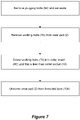
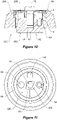
- the wear pad assembly 200 differs in that a base 240 comprises the curved external side surface comprising the screw thread 4, the drive socket 18, the internally tapered expandable collet 8 with slots 14, and the collet socket 10, and a wear pad 202 of wear pad assembly 200 comprises the externally and complementarily tapered mandrel portion 42.
- the wear pad assembly 200 further comprises a pair of spring washers 256, and the base 240 comprises a recessed face 242, the purpose of all of which will be expanded upon below.
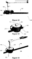
- the wear pad assembly 200 is assembled by inserting the externally tapered mandrel portion 42 of the wear pad 202 into the collet socket 10 of the base 240, and then screwing the base 240 into the threaded bore 104 using an appropriate tool inserted in driving socket 18, until the working face 6 of the wear pad 202 bears against the inner boom member 106, as illustrated in Figure 12 .
- the collet socket 10 is driven over the externally tapered mandrel portion 42 expanding the collet 8 in the threaded bore 104 to create an interference fit of the base 240 in the threaded bore 104.
- the O-ring 60 is then seated on the recessed face 242 to prevent ingress of dirt and moisture, the springs washers 256 are then seated atop of the O-ring 60, and then the working bolt 70 is passed through clearance holes 257 in the spring washers 256 and in the driving socket 18 in the base 240, and screwed into the threaded hole 19 in the wear pad 202.
- the wear pad 202 is pulled into and secured in the collet socket 10 by tensioning the working bolt 70 to a desired tension.
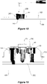
- the spring washers 256 flex into the recessed face 242 as the working bolt 70 is tensioned (see Figure 19 ), and maintain tension in the working bolt 70.
- the working bolt 70 is loosened until it is clear of the washers 256.
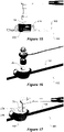
- the head of the working bolt 70 can then be struck with a hammer to advance the wear pad 202, as is illustrated in Figure 16 .
- a further bolt may be screwed into one of the bolt holes 54 in the base 240 until the end of this further bolt bears against the wear pad 202 to advance it.
- the spring washers 256 are then rotated until access apertures 258 through these align with a second drive socket 248 in the base 240, via which the base 240 can be advanced by its rotation until a desired tension is reached.
- the working bolt 70 is tensioned again, as is illustrated in Figure 18 .
- Wear pad assembly 200 provides increased load carrying capability, faster and simpler adjustment, and reduced manufacturing cost.
Landscapes
- Engineering & Computer Science (AREA)
- General Engineering & Computer Science (AREA)
- Mechanical Engineering (AREA)
- Earth Drilling (AREA)
- Jib Cranes (AREA)
- Manipulator (AREA)
Applications Claiming Priority (3)
| Application Number | Priority Date | Filing Date | Title |
|---|---|---|---|
| AU2014904267A AU2014904267A0 (en) | 2014-10-24 | Telescoping boom wear pad improvements | |
| AU2015902949A AU2015902949A0 (en) | 2015-07-24 | Telescoping boom wear pad improvements | |
| PCT/AU2015/000630 WO2016061612A1 (en) | 2014-10-24 | 2015-10-23 | Telescoping boom wear pad improvements |
Publications (3)
| Publication Number | Publication Date |
|---|---|
| EP3209596A1 EP3209596A1 (en) | 2017-08-30 |
| EP3209596A4 EP3209596A4 (en) | 2018-10-24 |
| EP3209596B1 true EP3209596B1 (en) | 2022-07-27 |
Family
ID=55759939
Family Applications (1)
| Application Number | Title | Priority Date | Filing Date |
|---|---|---|---|
| EP15851716.9A Active EP3209596B1 (en) | 2014-10-24 | 2015-10-23 | Wear pad for telescoping boom |
Country Status (9)
| Country | Link |
|---|---|
| US (1) | US10662035B2 (pl) |
| EP (1) | EP3209596B1 (pl) |
| CN (1) | CN107207224B (pl) |
| AU (2) | AU2015336926B2 (pl) |
| EA (1) | EA034299B1 (pl) |
| ES (1) | ES2927737T3 (pl) |
| PL (1) | PL3209596T3 (pl) |
| PT (1) | PT3209596T (pl) |
| WO (1) | WO2016061612A1 (pl) |
Cited By (1)
| Publication number | Priority date | Publication date | Assignee | Title |
|---|---|---|---|---|
| EP4484357A1 (en) * | 2023-06-09 | 2025-01-01 | Hyster-Yale Materials Handling, Inc. | Adjustable wear block for mast systems |
Families Citing this family (7)
| Publication number | Priority date | Publication date | Assignee | Title |
|---|---|---|---|---|
| US10066363B1 (en) * | 2017-07-13 | 2018-09-04 | Cnh Industrial America Llc | Wear pad system |
| IT201800004289A1 (it) * | 2018-04-06 | 2019-10-06 | Braccio telescopico per una gru di sollevamento di carichi. | |
| DE102018120808A1 (de) * | 2018-08-27 | 2020-02-27 | Renk Aktiengesellschaft | Lageranordnung und Einstellschraube zur Einstellung des Lagerspiels |
| GB2609669B (en) | 2021-08-13 | 2023-10-25 | Caterpillar Inc | Wear pad assembly and method for adjusting |
| GB2609668B (en) * | 2021-08-13 | 2023-09-27 | Caterpillar Inc | Wear pad, telescopic boom assembly and work machine |
| GB2620454B (en) * | 2022-07-08 | 2024-11-27 | Caterpillar Inc | Wear pad assembly |
| IT202300013788A1 (it) * | 2023-07-03 | 2025-01-03 | Jacques Tranchero | Gru con un sistema di sfilamento telescopico |
Family Cites Families (15)
| Publication number | Priority date | Publication date | Assignee | Title |
|---|---|---|---|---|
| US990065A (en) * | 1910-05-21 | 1911-04-18 | Arthur L Sargeant | Nut-lock. |
| US4134236A (en) * | 1976-11-26 | 1979-01-16 | Clark Equipment Company | Side shoe assembly for a crane boom |
| US4264265A (en) * | 1979-05-25 | 1981-04-28 | J. I. Case Company | Adjusting slide mechanism for telescoping boom |
| US4561552A (en) * | 1981-10-13 | 1985-12-31 | Kidde, Inc. | Attachment jib for cranes |
| GB2134072B (en) * | 1983-01-24 | 1985-10-09 | Coles Cranes Ltd | Booms |
| US5072993A (en) * | 1990-12-24 | 1991-12-17 | Caterpillar Inc. | Self-contained shim pack assembly |
| US5219254A (en) | 1992-02-14 | 1993-06-15 | Ball Sr Earl D | Expandable fastener and locking means therefor |
| GB9706445D0 (en) * | 1997-03-27 | 1997-05-14 | Bamford Excavators Ltd | Stabilizer leg |
| GB2375753B (en) * | 2001-03-24 | 2004-11-17 | Bamford Excavators Ltd | Wear pad |
| MXPA05003034A (es) * | 2002-09-21 | 2005-09-08 | Patrick W Breslin | Montaje sujetador de tornillo de chaveta seccionada y metodo. |
| US7537427B2 (en) | 2002-12-04 | 2009-05-26 | Tygard Machine & Manufacturing Company | Clamping apparatus |
| EP1605244A1 (en) | 2004-06-09 | 2005-12-14 | Boon, Mathilde Elisabeth | Fixative composition |
| ES2615427T3 (es) * | 2013-04-10 | 2017-06-06 | Atlas Copco Rock Drills Ab | Cojinete de deslizamiento para plumas telescópicas, de forma específica, para manipuladores o robots para hormigón proyectado |
| ITMO20130158A1 (it) * | 2013-05-31 | 2014-12-01 | Cnh Italia Spa | Dispositivo anti-usura regolabile per un braccio telescopico. |
| DE102013011180B4 (de) * | 2013-07-04 | 2020-09-10 | Liebherr-Werk Ehingen Gmbh | Kragenlagerung für einen Teleskopausleger sowie Teleskopausleger und Kran |
-
2015
- 2015-10-23 AU AU2015336926A patent/AU2015336926B2/en active Active
- 2015-10-23 US US15/521,603 patent/US10662035B2/en active Active
- 2015-10-23 EP EP15851716.9A patent/EP3209596B1/en active Active
- 2015-10-23 EA EA201790910A patent/EA034299B1/ru unknown
- 2015-10-23 WO PCT/AU2015/000630 patent/WO2016061612A1/en not_active Ceased
- 2015-10-23 PL PL15851716.9T patent/PL3209596T3/pl unknown
- 2015-10-23 PT PT158517169T patent/PT3209596T/pt unknown
- 2015-10-23 ES ES15851716T patent/ES2927737T3/es active Active
- 2015-10-23 CN CN201580070766.XA patent/CN107207224B/zh active Active
-
2020
- 2020-07-23 AU AU2020101459A patent/AU2020101459A4/en not_active Expired
Cited By (2)
| Publication number | Priority date | Publication date | Assignee | Title |
|---|---|---|---|---|
| EP4484357A1 (en) * | 2023-06-09 | 2025-01-01 | Hyster-Yale Materials Handling, Inc. | Adjustable wear block for mast systems |
| US12522482B1 (en) | 2023-06-09 | 2026-01-13 | Hyster-Yale Materials Handling, Inc. | Adjustable wear block for mast systems |
Also Published As
| Publication number | Publication date |
|---|---|
| US10662035B2 (en) | 2020-05-26 |
| CN107207224B (zh) | 2020-08-18 |
| EA201790910A1 (ru) | 2017-10-31 |
| EP3209596A1 (en) | 2017-08-30 |
| US20170240389A1 (en) | 2017-08-24 |
| EA034299B1 (ru) | 2020-01-27 |
| ES2927737T3 (es) | 2022-11-10 |
| PL3209596T3 (pl) | 2022-12-12 |
| AU2015336926A1 (en) | 2017-05-18 |
| PT3209596T (pt) | 2022-09-16 |
| AU2020101459A4 (en) | 2020-08-27 |
| WO2016061612A1 (en) | 2016-04-28 |
| CN107207224A (zh) | 2017-09-26 |
| EP3209596A4 (en) | 2018-10-24 |
| AU2015336926B2 (en) | 2020-04-30 |
| CA2965155A1 (en) | 2016-04-28 |
Similar Documents
| Publication | Publication Date | Title |
|---|---|---|
| AU2020101459A4 (en) | Telescoping boom wear pad improvements | |
| JP5154739B2 (ja) | 重量物用トグルボルト締付け具及び取付け分解方法 | |
| AU2023200199B2 (en) | A lining arrangement, and a method for fastening lining elements to a support structure | |
| US11555295B2 (en) | Ground engaging tool locking system | |
| US9476184B2 (en) | Excavator wear assembly | |
| DE112007002517T5 (de) | Gesteinsanker und Verankerungsvorrichtung | |
| US20090205228A1 (en) | Double Cam Taper Lock Connector Pin Apparatus | |
| CA2665256C (en) | Coupling pin and method of use thereof | |
| KR20150053071A (ko) | 풀림 방지용 체결구 | |
| DE102016100933B4 (de) | Montagewerkzeug, dessen Verwendung und Verfahren zur Befestigung eines Gewindeeinsatzes | |
| CA2979509A1 (en) | Expansion anchor | |
| EP3551896B1 (en) | Liner bolt | |
| DE102011052266A1 (de) | Selbstsichernde Befestigungsmittel sowie Befestigungsanordnung | |
| US8807901B1 (en) | Universal hammerless pin assembly | |
| CA2965155C (en) | Telescoping boom wear pad improvements | |
| WO2011138306A1 (en) | Radially expandable assembly and use thereof | |
| JP4914229B2 (ja) | 足場用壁つなぎ取付ボルト | |
| OA18725A (en) | Telescoping boom wear pad improvements. | |
| US20220032433A1 (en) | Hydraulic tensioner and method of tensioning | |
| DE10245377A1 (de) | Spannvorrichtung | |
| DE102018100355B4 (de) | Kupplungsvorrichtung zur Verbindung eines Lasthebemittels mit einer Last | |
| AU2007231751B2 (en) | A driling tool, a self drilling rock bolt, a drill bit and an anchoring device | |
| DE102020103577A1 (de) | Demontierbarer Bolzenanker und Verfahren zu seiner Demontage | |
| DE20107720U1 (de) | Lösehilfe für Werkzeuge | |
| EP2362017A2 (de) | Verbindungselement und Anordnung mit einem Verbindungselement |
Legal Events
| Date | Code | Title | Description |
|---|---|---|---|
| STAA | Information on the status of an ep patent application or granted ep patent |
Free format text: STATUS: THE INTERNATIONAL PUBLICATION HAS BEEN MADE |
|
| PUAI | Public reference made under article 153(3) epc to a published international application that has entered the european phase |
Free format text: ORIGINAL CODE: 0009012 |
|
| STAA | Information on the status of an ep patent application or granted ep patent |
Free format text: STATUS: REQUEST FOR EXAMINATION WAS MADE |
|
| 17P | Request for examination filed |
Effective date: 20170516 |
|
| AK | Designated contracting states |
Kind code of ref document: A1 Designated state(s): AL AT BE BG CH CY CZ DE DK EE ES FI FR GB GR HR HU IE IS IT LI LT LU LV MC MK MT NL NO PL PT RO RS SE SI SK SM TR |
|
| AX | Request for extension of the european patent |
Extension state: BA ME |
|
| DAV | Request for validation of the european patent (deleted) | ||
| DAX | Request for extension of the european patent (deleted) | ||
| REG | Reference to a national code |
Ref country code: DE Ref legal event code: R079 Ref document number: 602015080083 Country of ref document: DE Free format text: PREVIOUS MAIN CLASS: B66C0023640000 Ipc: B66C0023700000 |
|
| A4 | Supplementary search report drawn up and despatched |
Effective date: 20180920 |
|
| RIC1 | Information provided on ipc code assigned before grant |
Ipc: F16C 29/12 20060101ALI20180915BHEP Ipc: F16C 33/12 20060101ALI20180915BHEP Ipc: B66C 23/70 20060101AFI20180915BHEP Ipc: F16C 35/02 20060101ALI20180915BHEP Ipc: F16C 43/02 20060101ALI20180915BHEP Ipc: F16C 29/02 20060101ALI20180915BHEP Ipc: F16C 33/26 20060101ALI20180915BHEP Ipc: F16B 39/02 20060101ALI20180915BHEP |
|
| GRAP | Despatch of communication of intention to grant a patent |
Free format text: ORIGINAL CODE: EPIDOSNIGR1 |
|
| STAA | Information on the status of an ep patent application or granted ep patent |
Free format text: STATUS: GRANT OF PATENT IS INTENDED |
|
| GRAS | Grant fee paid |
Free format text: ORIGINAL CODE: EPIDOSNIGR3 |
|
| INTG | Intention to grant announced |
Effective date: 20220525 |
|
| GRAA | (expected) grant |
Free format text: ORIGINAL CODE: 0009210 |
|
| STAA | Information on the status of an ep patent application or granted ep patent |
Free format text: STATUS: THE PATENT HAS BEEN GRANTED |
|
| AK | Designated contracting states |
Kind code of ref document: B1 Designated state(s): AL AT BE BG CH CY CZ DE DK EE ES FI FR GB GR HR HU IE IS IT LI LT LU LV MC MK MT NL NO PL PT RO RS SE SI SK SM TR |
|
| REG | Reference to a national code |
Ref country code: CH Ref legal event code: EP |
|
| REG | Reference to a national code |
Ref country code: AT Ref legal event code: REF Ref document number: 1506958 Country of ref document: AT Kind code of ref document: T Effective date: 20220815 |
|
| REG | Reference to a national code |
Ref country code: DE Ref legal event code: R096 Ref document number: 602015080083 Country of ref document: DE |
|
| REG | Reference to a national code |
Ref country code: IE Ref legal event code: FG4D |
|
| REG | Reference to a national code |
Ref country code: PT Ref legal event code: SC4A Ref document number: 3209596 Country of ref document: PT Date of ref document: 20220916 Kind code of ref document: T Free format text: AVAILABILITY OF NATIONAL TRANSLATION Effective date: 20220909 |
|
| REG | Reference to a national code |
Ref country code: SE Ref legal event code: TRGR |
|
| REG | Reference to a national code |
Ref country code: LT Ref legal event code: MG9D |
|
| REG | Reference to a national code |
Ref country code: NL Ref legal event code: MP Effective date: 20220727 |
|
| PG25 | Lapsed in a contracting state [announced via postgrant information from national office to epo] |
Ref country code: RS Free format text: LAPSE BECAUSE OF FAILURE TO SUBMIT A TRANSLATION OF THE DESCRIPTION OR TO PAY THE FEE WITHIN THE PRESCRIBED TIME-LIMIT Effective date: 20220727 Ref country code: NO Free format text: LAPSE BECAUSE OF FAILURE TO SUBMIT A TRANSLATION OF THE DESCRIPTION OR TO PAY THE FEE WITHIN THE PRESCRIBED TIME-LIMIT Effective date: 20221027 Ref country code: NL Free format text: LAPSE BECAUSE OF FAILURE TO SUBMIT A TRANSLATION OF THE DESCRIPTION OR TO PAY THE FEE WITHIN THE PRESCRIBED TIME-LIMIT Effective date: 20220727 Ref country code: LV Free format text: LAPSE BECAUSE OF FAILURE TO SUBMIT A TRANSLATION OF THE DESCRIPTION OR TO PAY THE FEE WITHIN THE PRESCRIBED TIME-LIMIT Effective date: 20220727 Ref country code: LT Free format text: LAPSE BECAUSE OF FAILURE TO SUBMIT A TRANSLATION OF THE DESCRIPTION OR TO PAY THE FEE WITHIN THE PRESCRIBED TIME-LIMIT Effective date: 20220727 Ref country code: FI Free format text: LAPSE BECAUSE OF FAILURE TO SUBMIT A TRANSLATION OF THE DESCRIPTION OR TO PAY THE FEE WITHIN THE PRESCRIBED TIME-LIMIT Effective date: 20220727 |
|
| REG | Reference to a national code |
Ref country code: AT Ref legal event code: MK05 Ref document number: 1506958 Country of ref document: AT Kind code of ref document: T Effective date: 20220727 |
|
| PG25 | Lapsed in a contracting state [announced via postgrant information from national office to epo] |
Ref country code: IS Free format text: LAPSE BECAUSE OF FAILURE TO SUBMIT A TRANSLATION OF THE DESCRIPTION OR TO PAY THE FEE WITHIN THE PRESCRIBED TIME-LIMIT Effective date: 20221127 Ref country code: HR Free format text: LAPSE BECAUSE OF FAILURE TO SUBMIT A TRANSLATION OF THE DESCRIPTION OR TO PAY THE FEE WITHIN THE PRESCRIBED TIME-LIMIT Effective date: 20220727 Ref country code: GR Free format text: LAPSE BECAUSE OF FAILURE TO SUBMIT A TRANSLATION OF THE DESCRIPTION OR TO PAY THE FEE WITHIN THE PRESCRIBED TIME-LIMIT Effective date: 20221028 |
|
| PG25 | Lapsed in a contracting state [announced via postgrant information from national office to epo] |
Ref country code: SM Free format text: LAPSE BECAUSE OF FAILURE TO SUBMIT A TRANSLATION OF THE DESCRIPTION OR TO PAY THE FEE WITHIN THE PRESCRIBED TIME-LIMIT Effective date: 20220727 Ref country code: RO Free format text: LAPSE BECAUSE OF FAILURE TO SUBMIT A TRANSLATION OF THE DESCRIPTION OR TO PAY THE FEE WITHIN THE PRESCRIBED TIME-LIMIT Effective date: 20220727 Ref country code: DK Free format text: LAPSE BECAUSE OF FAILURE TO SUBMIT A TRANSLATION OF THE DESCRIPTION OR TO PAY THE FEE WITHIN THE PRESCRIBED TIME-LIMIT Effective date: 20220727 Ref country code: CZ Free format text: LAPSE BECAUSE OF FAILURE TO SUBMIT A TRANSLATION OF THE DESCRIPTION OR TO PAY THE FEE WITHIN THE PRESCRIBED TIME-LIMIT Effective date: 20220727 Ref country code: AT Free format text: LAPSE BECAUSE OF FAILURE TO SUBMIT A TRANSLATION OF THE DESCRIPTION OR TO PAY THE FEE WITHIN THE PRESCRIBED TIME-LIMIT Effective date: 20220727 |
|
| REG | Reference to a national code |
Ref country code: DE Ref legal event code: R097 Ref document number: 602015080083 Country of ref document: DE |
|
| PG25 | Lapsed in a contracting state [announced via postgrant information from national office to epo] |
Ref country code: SK Free format text: LAPSE BECAUSE OF FAILURE TO SUBMIT A TRANSLATION OF THE DESCRIPTION OR TO PAY THE FEE WITHIN THE PRESCRIBED TIME-LIMIT Effective date: 20220727 Ref country code: MC Free format text: LAPSE BECAUSE OF FAILURE TO SUBMIT A TRANSLATION OF THE DESCRIPTION OR TO PAY THE FEE WITHIN THE PRESCRIBED TIME-LIMIT Effective date: 20220727 Ref country code: EE Free format text: LAPSE BECAUSE OF FAILURE TO SUBMIT A TRANSLATION OF THE DESCRIPTION OR TO PAY THE FEE WITHIN THE PRESCRIBED TIME-LIMIT Effective date: 20220727 |
|
| REG | Reference to a national code |
Ref country code: CH Ref legal event code: PL |
|
| PLBE | No opposition filed within time limit |
Free format text: ORIGINAL CODE: 0009261 |
|
| STAA | Information on the status of an ep patent application or granted ep patent |
Free format text: STATUS: NO OPPOSITION FILED WITHIN TIME LIMIT |
|
| REG | Reference to a national code |
Ref country code: BE Ref legal event code: MM Effective date: 20221031 |
|
| GBPC | Gb: european patent ceased through non-payment of renewal fee |
Effective date: 20221027 |
|
| PG25 | Lapsed in a contracting state [announced via postgrant information from national office to epo] |
Ref country code: LU Free format text: LAPSE BECAUSE OF NON-PAYMENT OF DUE FEES Effective date: 20221023 Ref country code: AL Free format text: LAPSE BECAUSE OF FAILURE TO SUBMIT A TRANSLATION OF THE DESCRIPTION OR TO PAY THE FEE WITHIN THE PRESCRIBED TIME-LIMIT Effective date: 20220727 |
|
| 26N | No opposition filed |
Effective date: 20230502 |
|
| P01 | Opt-out of the competence of the unified patent court (upc) registered |
Effective date: 20230530 |
|
| PG25 | Lapsed in a contracting state [announced via postgrant information from national office to epo] |
Ref country code: LI Free format text: LAPSE BECAUSE OF NON-PAYMENT OF DUE FEES Effective date: 20221031 Ref country code: CH Free format text: LAPSE BECAUSE OF NON-PAYMENT OF DUE FEES Effective date: 20221031 |
|
| PG25 | Lapsed in a contracting state [announced via postgrant information from national office to epo] |
Ref country code: SI Free format text: LAPSE BECAUSE OF FAILURE TO SUBMIT A TRANSLATION OF THE DESCRIPTION OR TO PAY THE FEE WITHIN THE PRESCRIBED TIME-LIMIT Effective date: 20220727 |
|
| PG25 | Lapsed in a contracting state [announced via postgrant information from national office to epo] |
Ref country code: BE Free format text: LAPSE BECAUSE OF NON-PAYMENT OF DUE FEES Effective date: 20221031 |
|
| PG25 | Lapsed in a contracting state [announced via postgrant information from national office to epo] |
Ref country code: IE Free format text: LAPSE BECAUSE OF NON-PAYMENT OF DUE FEES Effective date: 20221023 Ref country code: GB Free format text: LAPSE BECAUSE OF NON-PAYMENT OF DUE FEES Effective date: 20221027 |
|
| PG25 | Lapsed in a contracting state [announced via postgrant information from national office to epo] |
Ref country code: HU Free format text: LAPSE BECAUSE OF FAILURE TO SUBMIT A TRANSLATION OF THE DESCRIPTION OR TO PAY THE FEE WITHIN THE PRESCRIBED TIME-LIMIT; INVALID AB INITIO Effective date: 20151023 |
|
| PG25 | Lapsed in a contracting state [announced via postgrant information from national office to epo] |
Ref country code: CY Free format text: LAPSE BECAUSE OF FAILURE TO SUBMIT A TRANSLATION OF THE DESCRIPTION OR TO PAY THE FEE WITHIN THE PRESCRIBED TIME-LIMIT Effective date: 20220727 |
|
| PG25 | Lapsed in a contracting state [announced via postgrant information from national office to epo] |
Ref country code: MK Free format text: LAPSE BECAUSE OF FAILURE TO SUBMIT A TRANSLATION OF THE DESCRIPTION OR TO PAY THE FEE WITHIN THE PRESCRIBED TIME-LIMIT Effective date: 20220727 Ref country code: IT Free format text: LAPSE BECAUSE OF FAILURE TO SUBMIT A TRANSLATION OF THE DESCRIPTION OR TO PAY THE FEE WITHIN THE PRESCRIBED TIME-LIMIT Effective date: 20220727 |
|
| PG25 | Lapsed in a contracting state [announced via postgrant information from national office to epo] |
Ref country code: BG Free format text: LAPSE BECAUSE OF FAILURE TO SUBMIT A TRANSLATION OF THE DESCRIPTION OR TO PAY THE FEE WITHIN THE PRESCRIBED TIME-LIMIT Effective date: 20220727 |
|
| PG25 | Lapsed in a contracting state [announced via postgrant information from national office to epo] |
Ref country code: MT Free format text: LAPSE BECAUSE OF FAILURE TO SUBMIT A TRANSLATION OF THE DESCRIPTION OR TO PAY THE FEE WITHIN THE PRESCRIBED TIME-LIMIT Effective date: 20220727 |
|
| PGFP | Annual fee paid to national office [announced via postgrant information from national office to epo] |
Ref country code: PT Payment date: 20251002 Year of fee payment: 11 |
|
| PG25 | Lapsed in a contracting state [announced via postgrant information from national office to epo] |
Ref country code: TR Free format text: LAPSE BECAUSE OF FAILURE TO SUBMIT A TRANSLATION OF THE DESCRIPTION OR TO PAY THE FEE WITHIN THE PRESCRIBED TIME-LIMIT Effective date: 20220727 |
|
| PGFP | Annual fee paid to national office [announced via postgrant information from national office to epo] |
Ref country code: DE Payment date: 20251028 Year of fee payment: 11 |
|
| PGFP | Annual fee paid to national office [announced via postgrant information from national office to epo] |
Ref country code: FR Payment date: 20251027 Year of fee payment: 11 |
|
| PGFP | Annual fee paid to national office [announced via postgrant information from national office to epo] |
Ref country code: SE Payment date: 20251024 Year of fee payment: 11 |
|
| PGFP | Annual fee paid to national office [announced via postgrant information from national office to epo] |
Ref country code: PL Payment date: 20251003 Year of fee payment: 11 |
|
| PGFP | Annual fee paid to national office [announced via postgrant information from national office to epo] |
Ref country code: ES Payment date: 20251118 Year of fee payment: 11 |