EP3209229B1 - Device for securing a rod to a bone - Google Patents
Device for securing a rod to a bone Download PDFInfo
- Publication number
- EP3209229B1 EP3209229B1 EP16770206.7A EP16770206A EP3209229B1 EP 3209229 B1 EP3209229 B1 EP 3209229B1 EP 16770206 A EP16770206 A EP 16770206A EP 3209229 B1 EP3209229 B1 EP 3209229B1
- Authority
- EP
- European Patent Office
- Prior art keywords
- tulip
- screw
- rod clamp
- accordance
- rod
- Prior art date
- Legal status (The legal status is an assumption and is not a legal conclusion. Google has not performed a legal analysis and makes no representation as to the accuracy of the status listed.)
- Active
Links
- 210000000988 bone and bone Anatomy 0.000 title claims description 12
- 241000722921 Tulipa gesneriana Species 0.000 claims description 82
- 230000002146 bilateral effect Effects 0.000 claims 1
- 210000003128 head Anatomy 0.000 description 9
- 210000001331 nose Anatomy 0.000 description 4
- 230000002093 peripheral effect Effects 0.000 description 4
- 230000007704 transition Effects 0.000 description 3
- 239000002639 bone cement Substances 0.000 description 2
- 235000011837 pasties Nutrition 0.000 description 2
- 238000010079 rubber tapping Methods 0.000 description 2
- 206010023509 Kyphosis Diseases 0.000 description 1
- 208000007623 Lordosis Diseases 0.000 description 1
- 238000013459 approach Methods 0.000 description 1
- 230000005540 biological transmission Effects 0.000 description 1
- 230000000903 blocking effect Effects 0.000 description 1
- 239000004568 cement Substances 0.000 description 1
- 238000004140 cleaning Methods 0.000 description 1
- 230000000295 complement effect Effects 0.000 description 1
- 239000012530 fluid Substances 0.000 description 1
- 230000004927 fusion Effects 0.000 description 1
- 230000003993 interaction Effects 0.000 description 1
- 239000007788 liquid Substances 0.000 description 1
- 230000007774 longterm Effects 0.000 description 1
- 239000000463 material Substances 0.000 description 1
Images


Classifications
-
- A—HUMAN NECESSITIES
- A61—MEDICAL OR VETERINARY SCIENCE; HYGIENE
- A61B—DIAGNOSIS; SURGERY; IDENTIFICATION
- A61B17/00—Surgical instruments, devices or methods, e.g. tourniquets
- A61B17/56—Surgical instruments or methods for treatment of bones or joints; Devices specially adapted therefor
- A61B17/58—Surgical instruments or methods for treatment of bones or joints; Devices specially adapted therefor for osteosynthesis, e.g. bone plates, screws, setting implements or the like
- A61B17/68—Internal fixation devices, including fasteners and spinal fixators, even if a part thereof projects from the skin
- A61B17/70—Spinal positioners or stabilisers ; Bone stabilisers comprising fluid filler in an implant
- A61B17/7001—Screws or hooks combined with longitudinal elements which do not contact vertebrae
- A61B17/7035—Screws or hooks, wherein a rod-clamping part and a bone-anchoring part can pivot relative to each other
- A61B17/7037—Screws or hooks, wherein a rod-clamping part and a bone-anchoring part can pivot relative to each other wherein pivoting is blocked when the rod is clamped
-
- A—HUMAN NECESSITIES
- A61—MEDICAL OR VETERINARY SCIENCE; HYGIENE
- A61B—DIAGNOSIS; SURGERY; IDENTIFICATION
- A61B17/00—Surgical instruments, devices or methods, e.g. tourniquets
- A61B17/56—Surgical instruments or methods for treatment of bones or joints; Devices specially adapted therefor
- A61B17/58—Surgical instruments or methods for treatment of bones or joints; Devices specially adapted therefor for osteosynthesis, e.g. bone plates, screws, setting implements or the like
- A61B17/68—Internal fixation devices, including fasteners and spinal fixators, even if a part thereof projects from the skin
- A61B17/70—Spinal positioners or stabilisers ; Bone stabilisers comprising fluid filler in an implant
- A61B17/7001—Screws or hooks combined with longitudinal elements which do not contact vertebrae
- A61B17/7032—Screws or hooks with U-shaped head or back through which longitudinal rods pass
-
- A—HUMAN NECESSITIES
- A61—MEDICAL OR VETERINARY SCIENCE; HYGIENE
- A61B—DIAGNOSIS; SURGERY; IDENTIFICATION
- A61B17/00—Surgical instruments, devices or methods, e.g. tourniquets
- A61B17/56—Surgical instruments or methods for treatment of bones or joints; Devices specially adapted therefor
- A61B17/58—Surgical instruments or methods for treatment of bones or joints; Devices specially adapted therefor for osteosynthesis, e.g. bone plates, screws, setting implements or the like
- A61B17/68—Internal fixation devices, including fasteners and spinal fixators, even if a part thereof projects from the skin
- A61B17/70—Spinal positioners or stabilisers ; Bone stabilisers comprising fluid filler in an implant
- A61B17/7074—Tools specially adapted for spinal fixation operations other than for bone removal or filler handling
- A61B17/7076—Tools specially adapted for spinal fixation operations other than for bone removal or filler handling for driving, positioning or assembling spinal clamps or bone anchors specially adapted for spinal fixation
-
- A—HUMAN NECESSITIES
- A61—MEDICAL OR VETERINARY SCIENCE; HYGIENE
- A61B—DIAGNOSIS; SURGERY; IDENTIFICATION
- A61B17/00—Surgical instruments, devices or methods, e.g. tourniquets
- A61B17/56—Surgical instruments or methods for treatment of bones or joints; Devices specially adapted therefor
- A61B17/58—Surgical instruments or methods for treatment of bones or joints; Devices specially adapted therefor for osteosynthesis, e.g. bone plates, screws, setting implements or the like
- A61B17/68—Internal fixation devices, including fasteners and spinal fixators, even if a part thereof projects from the skin
- A61B17/84—Fasteners therefor or fasteners being internal fixation devices
- A61B17/86—Pins or screws or threaded wires; nuts therefor
- A61B17/8625—Shanks, i.e. parts contacting bone tissue
- A61B17/863—Shanks, i.e. parts contacting bone tissue with thread interrupted or changing its form along shank, other than constant taper
-
- A—HUMAN NECESSITIES
- A61—MEDICAL OR VETERINARY SCIENCE; HYGIENE
- A61B—DIAGNOSIS; SURGERY; IDENTIFICATION
- A61B17/00—Surgical instruments, devices or methods, e.g. tourniquets
- A61B17/56—Surgical instruments or methods for treatment of bones or joints; Devices specially adapted therefor
- A61B17/58—Surgical instruments or methods for treatment of bones or joints; Devices specially adapted therefor for osteosynthesis, e.g. bone plates, screws, setting implements or the like
- A61B17/68—Internal fixation devices, including fasteners and spinal fixators, even if a part thereof projects from the skin
- A61B17/84—Fasteners therefor or fasteners being internal fixation devices
- A61B17/86—Pins or screws or threaded wires; nuts therefor
- A61B17/864—Pins or screws or threaded wires; nuts therefor hollow, e.g. with socket or cannulated
-
- A—HUMAN NECESSITIES
- A61—MEDICAL OR VETERINARY SCIENCE; HYGIENE
- A61B—DIAGNOSIS; SURGERY; IDENTIFICATION
- A61B90/00—Instruments, implements or accessories specially adapted for surgery or diagnosis and not covered by any of the groups A61B1/00 - A61B50/00, e.g. for luxation treatment or for protecting wound edges
- A61B90/03—Automatic limiting or abutting means, e.g. for safety
- A61B2090/037—Automatic limiting or abutting means, e.g. for safety with a frangible part, e.g. by reduced diameter
Definitions
- the invention relates to a device for fastening a rod to a bone according to the preamble of claim 1.
- the EP 2 363 086 A1 shows a transpedicular screw with a head 1 and a shaft provided with a screw thread, the head 1 being integral and rigidly connected to the shaft of the pedicle screw and the wall in the head 1 being interrupted by a diametrical slot through which the fastening or connecting rod 7 can extend.
- a "lower part" (lower part 3), which allows an orientation deviating from a right angle relative to the main axis - the pedicle screw - due to a partially cylindrical underside of the element 3 facing away from the connecting rod
- there is obviously no (rotational) degree of freedom since the side walls of part 3, like those of part 4, are obviously planar; nothing is said about this either.
- the diameter of the pressure element is reduced on at least one of its end faces compared to the inner diameter of the tulip.
- the lower part 3 of the D1 has its widest extent in the radial direction on its proximal end face.
- the invention is based on the object of further developing a device of the generic type in such a way that it enables further degrees of freedom and, in particular, a less stressful and less dangerous use for a patient.
- a rod clamp is provided between the latter and the (transverse) rod to be braced in the tulip head, which rod clamp can also be pivoted relative to the tensioning screw.
- the invention thus also includes a system of at least one device according to the invention and a (connecting) rod, in which the clamped rod between the tensioning screw and rod clamp is connected to each of the two at least via a contact line, possibly also over a large area, (but not only punctiform).
- a contact line possibly also over a large area, (but not only punctiform).
- a preferred embodiment of the device according to the invention is characterized in that the rod clamp and tensioning screw have spherical zones on both sides facing one another and oriented obliquely to a main axis (A), over which they can be pivoted relatively.
- the spherical zones are preferably formed in the jacket area of the tensioning screw and rod clamp.
- the clamping screw At its distal end of the end face, the clamping screw preferably has an annular end face in the form of a spherical zone (as a jacket of a spherical layer) and the rod clamp a corresponding proximal end face in the form of a spherical zone.
- Proximal denotes an area of the device facing an operator or user - axially - and, distally, an area of the device facing away from this and thus facing a patient or lying in this area of the device during use.
- a rod clamp adapter connecting the clamping screw and the rod clamp is provided, the rod clamp adapter being a ring part with proximal outwardly radially directed projections which engage in radial incisions in the clamping screw with play, in particular distal, also radially outwardly directed projections being given that engage in radial notches in the rod clamp.
- a radial annular groove is formed as an undercut proximally behind the end face of the clamping screw.
- a rod clamp for the rod to be clamped points to her The proximal end facing the clamping screw has an end face which also runs obliquely to a main longitudinal axis and corresponds to the end face.
- the rod clamp is also provided with a radial annular groove on the inside of its jacket. Radially outwardly formed projections of the annular rod clamp adapter engage in the annular groove in order to secure the rod clamp on the clamping screw against falling out.
- the tensioning screw and the rod clamp have undercuts reaching behind one another, whereby a pivotable connection between the tensioning screw and the rod clamp is provided.
- the undercut of the clamping screw is formed by an annular projection and / or that the undercut of the rod clamp is formed on more than two elastic fingers arranged around the circumference.
- the number of rings and undercuts on these is preferably four to eight.
- the clamping screw has an inner cone which tapers away from the undercut. This ensures that even with a non-axial alignment, i.e. pivoting or tilting between the tensioning screw and the rod clamp, there is always a fixed radial position between the two parts, since the area of the rod clamp moving towards the proximal or tapered area of the inner cone of the tensioning screw is due to the tapered conical design is pressed to the side and the opposite in the enlarged or distal area of the recess of the clamping screw corresponding to the side in this area also rests on the circumferential wall of the clamping screw.
- the rod clamp has a part-circular recess on its side facing away from the clamping screw.
- a partially circular recess has an axis of symmetry perpendicular to the main axis of symmetry of the tensioning clamp and, in the case of an axially elongated arrangement, the same with the axis of symmetry of the tensioning screw.
- the part-circular recess of the rod clamp can therefore encompass the rod over part of its circumference.
- the tensioning screw has an asymmetrical thread, in particular a flank of the thread of the tensioning screw that is directed proximally to the tightening direction below an angle of less than or equal to 5 °, in particular less than or equal to 3 ° or not equal to 0 °, to a radial plane to the axis of symmetry of the clamping screw and / or a flank of the thread of the clamping screw directed in the tightening direction (distal) extends at an angle other than 90 ° to the
- the axis of symmetry of the clamping screw preferably by 30 °, extends to a radial plane.
- the flanks are directed proximally to the vertical longitudinal axis of the screw.
- the clamping screw has a multiple rotationally symmetrical (non-cylindrical) recess on its side facing away from the rod clamp.
- a complementary screw tool for screwing the screw into the tulip of the device can thus engage with this proximal, non-cylindrical recess of the clamping screw.
- Another embodiment of the invention is characterized in that the pressure element is tiltably mounted in the tulip.
- the diameter of the pressure element is reduced on at least one of its end faces compared to the inner diameter of the tulip, so that the pressure element can be tilted within the tulip.
- the pressure element of the tulip tapers from its distal to its proximal end face, so that there is a radial clearance proximally between the inner wall of the tulip and the outer wall of the pressure element or that the inner wall of the tulip extends from the height of the proximal to the height of the distal end face of the pressure element expanded while ensuring a radial play between the pressure element and tulip at the level of the distal end face of the pressure element.
- the pressure element that is distally opposite the rod clamp and clamps the rod between it and itself in connection or relationship to the interior of the surrounding tulip is designed and / or supported such that the pressure element also enables and supports the alignment of the clamped rod made possible by the clamping device not disabled.
- a fastening device has a pedicle screw, a pressure element and a tulip. It also has a tensioning device with a tensioning screw and a rod clamp. All of these parts are cannulated, i.e. they have an axially extending central cavity.
- the tulip holds the pedicle screw and, after screwing the latter into a bone, serves to support a rod.
- the tulip is therefore a deposit of rods and is also referred to as such.
- the tulip is proximally connected to a tulip extension via a predetermined breaking point.
- Tulip and tulip extension have an internal thread extending over both and in the wall of both diametrically opposite elongated holes.
- the pedicle screw has a pedicle screw shaft with a self-tapping pedicle thread and, at the proximal end, a pedicle screw head which is surrounded by the tulip.
- a pressure element for the rod is arranged as an abutment in the distal area of the tulip.
- the screw shaft of the pedicle screw has a double thread, in particular a proximal area of the screw shaft is designed as a quadruple thread, preferably over a length of a quarter of the pedicle screw shaft. This results in a better hold of the screw in the bone.
- a double thread has two screw threads. These are twisted into one another.
- the transition from screw thread projection or serration to the screw shaft is rounded off with a finite radius of curvature of the transition. This increases the stability of the screw and prevents the screw flanks from breaking off.
- the pedicle screw shaft is provided with openings around a jacket to its inner lumen.
- Pasty masses such as bone cement, in particular, can be introduced through a lumen of the screw and openings. It is essential that the breakthroughs are present in the distal area of the screw so that they can be removed after the Screw lie within the vertebral body (and not in the bone area) so that cement can then be introduced through this into the interior of the vertebral body for fixation.
- An external thread of the clamping screw is matched to an internal thread of the tulip.
- a rod inserted in the tulip is clamped between the rod clamp, which encompasses it from the proximal side and on which the clamping screw acts, and the distal pressure element, by means of which the rod can be clamped at angles equal to or not equal to 90 °, in particular to the device axis .
- clamping screw thread At the proximal end of the clamping screw there is a multiple, non-cylindrical recess for positive engagement with a screwing tool to transmit a torque to the clamping screw.
- the outside of the clamping screw is provided with an asymmetrical clamping screw thread, in particular in the form of a special buttress thread.
- the tensioning screw has proximally behind its distal end face an annular projection in the form of an inner cone extending proximally from the distal end face, which is connected via an undercut proximally to an inner cone tapering the lumen of the tensioning screw in the proximal direction, which radially at the distal end area of the recess of the tensioning screw has a larger diameter than the recess.
- the rod clamp has a number of circumferentially juxtaposed and proximally and radially inwardly directed elastic fingers with radially outwardly pointing noses which cooperate with the undercuts of the clamping screw in that the noses engage with their undercuts in the undercut of the clamping screw formed by the annular projection.
- the distal end face of the rod clamp has a partially cylindrical clamping recess for receiving the transverse rod.
- a polyaxial pressure element has a partially cylindrical recess on its proximal side for partially embracing or receiving the rod, while another hemispherical or dome-shaped recess is provided on the distal end face of the pressure element in order to grasp a spherical screw head of the pedicle screw.
- the pressure element - distal compared to the rod - has a jacket which tapers from its distal end to the proximal end, so that a gap is formed between this and the inner wall of the tulip. This enables the pressure element to be tilted within the tulip in relation to an axially formed central position.
- the partially cylindrical recess has a radius of curvature such that rods with different diameters, such as between 5 mm and 6 mm, can be used.
- the pressure element has pressure surfaces on its outside for transverse screws that can be screwed in radially from the outside through the tulip for fixing the pressure element inside the tulip.
- the polyaxial pedicle screw has a spherical pedicle screw head which can be pivoted in all directions without restriction in the spherical recess on the distal area of the polyaxial pressure element.
- the screw head and thus the pedicle screw 2 is held captively in the tulip by means of the pressure element, since at its distal end it has an opening that is narrowed in relation to the diameter of the screw head.
- a monoaxial pressure element has a flat, frustoconical distal end face facing the screw head of the pedicle screw, with a conical ring-shaped peripheral edge which surrounds a central opening.
- the pressure element and pedicle screw can be rotated relative to one another, but always remain monoaxially aligned along an axis that corresponds to the axis of the tulip and the clamping screw screwed into it.
- the inner wall of the tulip has a step and, proximally behind this, an expansion which tapers monoaxially in the proximal direction.
- the screw head extends proximally up to this step into the tulip.
- the - monoaxial - The pressure element only begins there distally and has a smaller diameter than the extension of the tulip at its distal end, so that there is a certain lateral play and so the monoaxial pressure element in the tulip can be tilted slightly in order to allow the clamping device not to hinder the eccentric alignment of the rod, but rather to accommodate and enable it.
- a monoaxial pedicle screw has at its proximal end a - monoaxial - pedicle screw head which can be pivoted accordingly.
- the screw head has a cylindrical jacket and a flat, proximal end-face recess with an edge which is likewise conical-ring-shaped and adapted to the peripheral edge of the pressure element.
- the clamping device with the rod clamp allows tilted arrangements of the connecting rod to be adjusted by corresponding pivoting movement of the rod clamp and the pressure element, which on the one hand reduces the stress on the fastening device and on the other hand at least considerably reduces the stress on the patient; the stability of the fastening device, in particular its long-term stability, are significantly increased as a result. Due to the variability of the alignment of the cross bar in the device, the stability of the structure is thus improved.
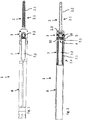
- Fig. 1 shows a fastening device 1 with a - polyaxial - pedicle screw 2 and a tulip 3.
- the device 1 has a main axis A in its longitudinal direction. It also has a clamping device 4 with a clamping screw 5 and a rod clamp 6, which in section in the Fig. 2 and especially too Fig. 3 are shown. All of these parts are cannulated, ie they have an axially extending central cavity.
- proximal denotes an area of the device 1 facing a surgeon or user - axially - and distally an area of the device 1 facing away from the latter and thus facing a patient or lying in this area of the device 1 during use.
- the tulip 3 holds the pedicle screw 2 and, after screwing the latter into a bone, in particular a vertebra, serves to support a rod 10 ( Fig. 2 , 3 ) which extends in particular in the direction of the spine or a long bone or in the direction of a flat bone and which is also held by further tulips with pedicle screws on another bone / vertebra or another location, e.g. a long bone, and the bones / vertebrae so can fix.
- the tulip 3 is thus a rod deposit and is also referred to as such.
- the tulip 3 is initially connected to a tulip extension 7 via a predetermined breaking point 7.3.
- the predetermined breaking point 7.3 has a radially reduced cross section or a reduced wall thickness.
- the latter has an external thread (not shown) for connection to an extension shaft 8 having a corresponding internal thread.
- the tulip 3 and the tulip extension 7 are cannulated like the extension shaft 8.
- Tulip 3 and tulip extension 7 have an internal thread 3.1, 7.1 extending over both of them. Further extend in the distal area of the tulip extension 7 and in the proximal area of the tulip 3 in the wall of both diametrically opposed elongated holes 3.2, 7.2, which extend axially over most of the tulip extension 7 and over approximately half of the tulip 3.
- the pedicle screw 2 has a pedicle screw shaft 2.1 with a self-tapping pedicle thread 2.2. At the proximal end of the pedicle screw 2, a pedicle screw head 2.3 is formed, which is encompassed by the tulip 3 ( Figs. 1 to 3 ).
- a pressure element 9 is arranged, the mode of operation of which is described below.
- the illustrated pedicle screw 2 has a double thread, ie two screw threads S1, S2 ( Fig. 15 ).
- the pedicle screw 2 can also have a single thread or a multiple thread (other than two).
- the pedicle screw shaft 2.1 is provided with openings 2.4 in a jacket 2.5 to an inner lumen 2.6 of the pedicle screw 2.
- the lumen 2.6 axially penetrates the entire pedicle screw 2. Liquids and / or in particular pasty materials such as cleaning fluids or bone cement can be introduced through the lumen 2.6 and the openings 2.4.
- An external thread 5.2 of a clamping screw 5 is matched to an internal thread 3.1 of the tulip 3 (described in more detail below).
- a rod 10 clamped in the tulip 3 can be seen (in section), which is clamped between the rod clamp 6 which engages around it from the proximal side and which the clamping screw 5 acts on, and the distal pressure element 9.
- the clamping of the rod 10 will be discussed further below.
- the Fig. 3a shows a section through the device 1 according to the invention with a rod 10 at an angle not equal to 90 ° to the device axis - how such an alignment is made possible by the configuration of the individual elements described below.
- the tensioning screw 5 ( Fig. 3 , 3a ) has an axial axis of symmetry that coincides with the main axis A.
- At the proximal At the end of the clamping screw 5 there is a multiple, non-cylindrical recess 5.1 which provides a screw tool (screwdriver, not shown) with a form-fitting engagement for transmitting a torque to the clamping screw 5.
- the recess 5.1 can be designed as a square or polygon, in particular also as a Torx profile.
- the outside of the tensioning screw 5 is provided with the asymmetrical tensioning screw thread 5.2, the tightening direction F being directed distally.
- the clamping screw thread 5.2 is designed as a buttress thread.
- Other thread types, in particular other asymmetrical thread types, are also possible.
- flanks 5.3, 5.4 are inclined in the same direction from the inside to the outside in the proximal direction with respect to (perpendicular to the axis) radial planes, namely the distally directed flank 5.3 of a tooth body here by 30 ° and proximally directed flank 5.4 of the screw thread by 3 °, so that the flank angle (between the two flanks) is 27 °.
- a buttress thread is highly resilient to forces acting against the tightening direction.
- the clamping screw 5 in this first embodiment has Fig. 3 an annular end face 5.9 in the form of a spherical zone (a spherical layer as a jacket) running obliquely from the outside distally and proximally on the inside to the axis A. Proximally behind this a radial annular groove 5.10 is formed as an undercut.
- a rod clamp 6 for the rod 10 to be clamped has its facing towards the clamping screw 6 proximal end has an end face 6.7 which also runs obliquely to the axis A and corresponds to the end face 5.9.
- the rod clamp 6 is also provided with a radial annular groove 6.8 on the inside of its jacket.
- annular rod clamp adapter (6a) In the annular grooves 5.10, 6.8 - here four - radially outwardly directed projections 6a.1 and 6a.2 of an annular rod clamp adapter (6a), which are not evenly arranged over the circumference, engage in order to secure the rod clamp 6 on the tensioning screw 5 against falling out .
- the rod clamp adapter is preferably welded to the rod clamp 6.
- Fig. 5 shows a clamping screw 5 of the second embodiment of the clamping device 4 in an axial longitudinal section.
- 3a is the clamping screw described, reference is made to the description there.
- the clamping screw 5 has proximally behind its distal end face an annular projection in the form of an inner cone that extends proximally from the distal end face, to which a lumen 5.7 of the clamping screw 5 is connected proximally via an undercut 5.6, which tapers in the proximal direction and which axially at the distal end area the recess 5.1 of the clamping screw 5 ends and there has a larger radial diameter than the recess 5.1.
- the rod clamp 6 is also ring-shaped with a lumen ( Fig. 6 ) and provided on its distal end face with a bore 6.1 which extends axially over approximately half the height of the rod clamp 6 and has a constant radial cross section.
- the rod clamp 6 has a row of side by side in the circumferential direction and in the proximal direction and radially inwardly directed elastic fingers 6.2, which at their end region have radially outwardly pointing noses 6.3, which form undercuts 6.4.
- the axial axis of symmetry S ′ of the rod clamp 6 coincides with the axis of symmetry S of the clamping screw 5. The interaction of the clamping screw 5 with the rod clamp 6 will be discussed further below.
- the distal end of the rod clamp 6 has a partially cylindrical clamping recess 6.5 for receiving the transverse rod 10 ( Fig. 7 ).
- the rod clamp 6 has approaches 6.6 on both sides in the direction of one axis of symmetry of the partially cylindrical recess 6.5.
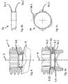
- Fig. 8 shows the clamping device 4 with the clamping screw 5 and rod clamp 6 plugged together.
- the clamping screw 5 and the rod clamp 6 were moved axially towards one another so that the lugs 6.3 of the rod clamp 15 initially come into contact with the conical annular projection 5.5 of the clamping screw 5.
- the fingers 6.2 With further axial movement, the fingers 6.2 are pressed radially inward by the conical flank of the annular projection 5.5, which allows a further relative axial movement. If the lugs 6.3 of the fingers 6.2 reach the undercut 5.6 beyond the annular projection 5.5, the lugs 6.3 with undercuts 6.4 snap into the undercut 5.6 of the clamping screw 5 formed by the annular projection 5.5.
- Figures 8 and 9 show sectional views rotated by 90 ° to each other.
- a tilting movement of the rod clamp 6 is in the Clamping screw 5 possible, as shown in the Figures 10 and 11 is shown with a tilt angle of about 6 ° to the axis of symmetry S of the clamping screw 5. Due to the design of the proximally tapering inner cone 5.8, even in the tilted position of the rod clamp 6, its lugs 6.3 are in contact with the inner wall of the inner cone 5.8. In this way, the radial fixing of the rod clamp 6 is ensured in the axially aligned and tilted position.
- Fig. 11 shows an axial section of the clamping device 4 rotated by 90 ° Fig. 10 .
- the Figs. 1 to 4 show - as I said - a polyaxial configuration of the fastening device 1.
- This also has a polyaxial pressure element 9 ( Fig. 12-14 ) and this described pedicle screw 2 with a spherical screw head 2.3 ( Figures 15, 16 ) on.
- the polyaxial pressure element 9 ( Fig. 12-14 ) has a partially cylindrical recess 9.1 on its proximal side for partially embracing or receiving the rod 10, while a further hemispherical or dome-shaped recess 9.2 is provided on the distal end face of the pressure element 9 in order to grasp the spherical screw head 2.3 of the pedicle screw 2 .
- the pressure element 9, which is distal in relation to the rod 10, has a jacket 9.4 which tapers from its distal end to the proximal end, so that a gap 9.5 is formed between it and the inner wall of the tulip 3 (in particular Fig. 3 ).
- the pressure element 9 can assume a tilted orientation made possible by the described clamping device 4 of the rod 10 and be clamped in this, namely in an angular offset with respect to the orientation of the opposing elongated holes 3.2 in the walls of the tulip 3, i.e. also in an orientation tilted relative to the axis perpendicular.
- the clamping device 4 enables such tilted orientations of the rod 10 and does not hinder them.
- the partially cylindrical recess 9.1 has a larger radius of curvature than that in the Fig. 3 rod 10 shown. This results in a play 9.6 perpendicular to the extension of the rod 10 at the proximal opening of the pressure element 9 approximately halfway up the rod 10. This allows rods 10 with different diameters to be used in the same fastening device 1. If the rod shown has, for example, a diameter of 5.5 mm, as it is used and customary by most people and the cylindrical recess has a diameter of 6 mm, a rod with a diameter of 6 mm can also be used, for example, for strong, especially young people People, for whom a rod with a diameter of 5.5 mm often does not have the necessary strength.
- two opposite, recessed pressure surfaces 9.3 are provided in the distal area for transverse screws 3.5 that can be screwed in radially from the outside through the tulip 3 to fix the pressure element 9 inside the tulip 3.
- the polyaxial pedicle screw 2 itself is in the Figures 15 and 16 and has - as already stated above - the spherical pedicle screw head 2.3.
- the pedicle screw head 2.3 can be pivoted in all directions in the dome-shaped recess 9.2 on the distal area of the polyaxial pressure element 9.
- the screw head 2.3 and thus the pedicle screw 2 is held captively in the tulip 3 by means of the pressure element 9, since at its distal end 3.3 it has an opening that is narrower than the diameter of the screw head ( Fig. 1-4 ).
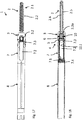
- a monoaxial device of the Fig. 17 In a monoaxial device of the Fig. 17
- the clamping device 4 with clamping screw 5 and rod clamp 6 is the same as in the previously described polyaxial fastening device. Only a - monoaxial - pedicle screw head 2.3a of the pedicle screw 2 and a - monoaxial - pressure element 9a, which are shown in an enlarged view in FIGS Figures 19-24 are shown.
- FIGS 17 to 19 show a monoaxial fastening device 1 in side view ( Fig. 17 ) or longitudinal section ( Fig. 18 , 19th ).
- the same parts and features are generally denoted by the same reference numerals as in the polyaxial configuration of FIG Figures 1 to 16 , which is also referred to. The different versions are explained below.
- the tulip 3 with the monoaxial pressure element 9 can be seen distal of the clamped transverse rod 10.
- the pressure element 9 holds the pedicle screw head 2.3a, while the pedicle screw 2 itself is screwed into a vertebral body and is fixed (not shown).
- Proximal of the transverse rod 10 the clamping screw 5 screwed in along the internal thread 7.1 of the tulip extension 7 in the screwing direction F and acting on the rod clamp 6 is located in the tulip 3 with the aid of a turning tool (not shown). This takes - here - a tilted position and can thus hold the transverse rod 10 vertically in a polyaxial extension direction.
- the monoaxial pressure element 9a like the polyaxial pressure element 9, has a proximal, partially cylindrical recess 9.1 for partially receiving the rod 10, but unlike the screw head 2.3a of the pedicle screw 2, a flat, frustoconical distal end face 9a.2 with a conical annular peripheral edge 9a.3 surrounding a central opening 9a.4 ( Figures 20-22 ).
- the inner wall of the tulip 3 has a step 3.7 and, proximally behind this, an enlargement 3.8 which tapers monoaxially in the proximal direction.
- the screw head 9a extends proximally up to this step 3.7 into the tulip 3.
- the - monoaxial - pressure element 9a begins distally only there and has a smaller diameter than the extension 3.8 at its distal end, so that there is a certain lateral play there and the monoaxial pressure element 9a in the tulip 3 can also be tilted slightly in order to achieve an eccentric alignment of the rod permitted by the clamping device 4, as shown in FIG Fig. 4 , is shown for the polyaxial device 1, not to hinder, but rather to accommodate and enable.
- the Fig. 22 shows the monoaxial pressure element 9a in a perspective view; the recess 9.1, which is wider than the transverse frame of the rod 10, allows the rod 10 to be fixed eccentrically.
- the pedicle screw 2 as in particular in the Fig. 18 , 23 and 24 is shown, has at its proximal end a - monoaxial pedicle screw head 2.3a, which can be pivoted accordingly.
- the screw head 2.3a has a cylindrical jacket 2.5 and a flat, proximal end-face recess 2.5a, which has an edge 2.6a which is also conical ring-shaped and is adapted to the peripheral edge 9a.3 ( Fig. 19 , 24 ).
- the illustrated pedicle screw 2 has a quadruple thread 2.2.1 in the proximal area of the screw shaft 2.1 over about a quarter of the length of the thread or screw shaft 2.1.
- Such a configuration can also be used for a polyaxial pedicle screw according to FIGS Figs. 1 to 4 , 15, 16 be provided.
Description
Die Erfindung betrifft eine Vorrichtung zum Befestigen eines Stabs an einem Knochen nach dem Oberbegriff des Anspruchs 1.The invention relates to a device for fastening a rod to a bone according to the preamble of
Insbesondere bei beschädigten Bandscheiben aber auch sonstigen Schädigungen der Wirbelsäule ist es oft notwendig, zwei oder mehr benachbarte Wirbelkörper durch Spondylodese (Wirbelkörperverblockung) zu versteifen. Hierzu werden in die Wirbelkörper Pedikelschrauben eingeschraubt, die rückwärtig proximal eine Tulpe oder Stablagerung tragen. Ein jeweils eine Pedikelschraube bzw. Tulpen in mehreren Wirbeln verbindenden Quer-Stab ist in den Tulpen mittels Spannschrauben verspannt.In the case of damaged intervertebral discs in particular, but also other types of damage to the spine, it is often necessary to stiffen two or more adjacent vertebral bodies by spondylodesis (vertebral body blocking). For this purpose, pedicle screws are screwed into the vertebral bodies, which carry a tulip or rod deposit at the proximal rear. A transverse rod connecting a pedicle screw or tulips in several vertebrae is braced in the tulips by means of tensioning screws.
Dabei ist es zwar bekannt die Pedikelschrauben mit einem Kugelkopf oder einem Teilkugelkopf auszubilden und zwischen Stab und Pedikelschraubenkopf ein Andruckelement vorzusehen, womit Tulpenkopf und Pedikelschraube mono- oder polyaxial relativ zueinander unter einem Winkel ausgerichtet werden können. Andruckschrauben wirken aber immer unmittelbar auf dem (Quer-)Stab. Krümmungen der Wirbelsäule (Kyphose - Brust, Lordose - Lende) können zwar durch entsprechend gebogene Verbindungsstäbe berücksichtigt bzw. angepasst werden. Dennoch können bei den bekannten Vorrichtungen unerwünschte Spannungen auftreten, da die den Stab im Tulpenkopf festspannende Spannschraube immer senkrecht, d.h. flächig in Richtung ihrer eigenen Symmetrieachse gegen den Stab einwirkt und diesen derart senkrecht auch im Tulpenkopf verspannt.It is known to design the pedicle screws with a spherical head or a partial spherical head and to provide a pressure element between the rod and the pedicle screw head, whereby the tulip head and the pedicle screw are aligned monoaxially or polyaxially relative to one another at an angle can be. However, pressure screws always act directly on the (transverse) rod. Curvatures of the spine (kyphosis - chest, lordosis - loin) can be taken into account or adjusted using appropriately curved connecting rods. Nevertheless, undesirable tensions can occur in the known devices, since the tensioning screw tightening the rod in the tulip head always acts vertically, ie flat in the direction of its own axis of symmetry, against the rod and also braces it vertically in the tulip head.
Die
Der Erfindung liegt die Aufgabe zugrunde, eine gattungsgemäße Vorrichtung dahingehend weiterzuentwickeln, dass sie weitergehende Freiheitsrade und insbesondere einen für einen Patienten weniger belastenden und weniger gefährlichen Einsatz ermöglicht.The invention is based on the object of further developing a device of the generic type in such a way that it enables further degrees of freedom and, in particular, a less stressful and less dangerous use for a patient.
Erfindungsgemäß wird die oben genannte Aufgabe mit einer gattungsgemäßen Vorrichtung gelöst, die die kennzeichnenden Merkmale des Anspruchs 1 aufweist.According to the invention, the above-mentioned object is achieved with a generic device which has the characterizing features of
Erfindungsgemäß ist also zusätzlich zur Spannschraube eine zwischen dieser und den in dem Tulpenkopf zu verspannenden (Quer-)Stab angeordnete Stabklemme vorgesehen, die darüber hinaus relativ zur Spannschraube schwenkbar ist. Hierdurch können bei der Spondylodese mittels eines solchen Verbindungsstabes insbesondere über mehrere zu versteifende Wirbelkörper auftretende Unregelmäßigkeiten ausgeglichen werden.According to the invention, in addition to the tensioning screw, a rod clamp is provided between the latter and the (transverse) rod to be braced in the tulip head, which rod clamp can also be pivoted relative to the tensioning screw. In this way, during spinal fusion, by means of such a connecting rod, irregularities occurring in particular over several vertebral bodies to be stiffened can be compensated for.
Es ergibt sich so nach Festspannen immer unabhängig vom Durchmesser des Stabes (im vorgegebenen Bereich von insbesondere 5 mm bis 6 mm) zumindest ein linienförmiger Kontakt, eine Kontaktlinie, und damit eine zuverlässige Verbindung und gleichmäßige Kraftübertragung. Ein lediglich punktförmiger Kontakt ist ausgeschlossen.After tightening, there is always at least one linear contact, a contact line, and thus a reliable connection and uniform force transmission, regardless of the diameter of the rod (in the specified range of in particular 5 mm to 6 mm). A point-like contact is not possible.
Insbesondere beinhaltet die Erfindung damit auch ein System aus mindestens einer erfindungsgemäßen Vorrichtung und einem (Verbindungs)-Stab, bei dem der eingespannte Stab zwischen Spannschraube und Stabklemme zu jeder der beiden zumindest über eine Kontaktlinie in Verbindung steht, gegebenenfalls auch flächig, (aber eben nicht lediglich punktförmig). Dies gilt für Verbindungsstäbe mit unterschiedlichen Durchmessern (in einem beschränkten Bereich), vorzugsweise zwischen 5 mm und 6 mm.In particular, the invention thus also includes a system of at least one device according to the invention and a (connecting) rod, in which the clamped rod between the tensioning screw and rod clamp is connected to each of the two at least via a contact line, possibly also over a large area, (but not only punctiform). This applies to connecting rods with different Diameters (in a limited range), preferably between 5 mm and 6 mm.
Eine bevorzugte Ausgestaltung der erfindungsgemäßen Vorrichtung zeichnet sich dadurch aus, dass die Stabklemme und Spannschraube einander zugewandte schräg zu einer Hauptachse (A) ausgerichtete beidseitige Kugelzonen aufweisen, über die sie relativ verschwenkbar sind. Die Kugelzonen sind bevorzugt in dem Mantelbereich von Spannschraube und Stabklemme ausgebildet. Vorzugsweise weist die Spannschraube an ihrem distalen Ende der Stirnseite eine von außen distal nach innen proximal schräg verlaufende ringförmige Stirnseite in Form einer Kugelzone auf (als Mantel einer Kugelschicht) und die Stabklemme eine korrespondierende proximale Stirnseite in Form einer Kugelzone auf.A preferred embodiment of the device according to the invention is characterized in that the rod clamp and tensioning screw have spherical zones on both sides facing one another and oriented obliquely to a main axis (A), over which they can be pivoted relatively. The spherical zones are preferably formed in the jacket area of the tensioning screw and rod clamp. At its distal end of the end face, the clamping screw preferably has an annular end face in the form of a spherical zone (as a jacket of a spherical layer) and the rod clamp a corresponding proximal end face in the form of a spherical zone.
"Proximal" bezeichnet einen einem Operateur oder Benutzer - axial - zugewandten, distal einen diesem abgewandten und damit einem Patienten zugewandten bzw. in diesem liegenden Bereich der Vorrichtung bei ihrem Einsatz.“Proximal” denotes an area of the device facing an operator or user - axially - and, distally, an area of the device facing away from this and thus facing a patient or lying in this area of the device during use.
In bevorzugter Weiterbildung ist dabei ein Spannschraube und Stabklemme verbindender Stabklemmenadapter vorgesehen, wobei der Stabklemmenadapter ein Ringteil mit proximalen nach außen radial gerichtete Vorsprüngen ist, die in radiale Einschnitte in der Spannschraube unter Spiel eingreifen, wobei insbesondere distale, ebenfalls radial nach außen gerichtete Vorsprünge vorgegeben sind, die in radiale Einschnitte der Stabklemme eingreifen.In a preferred development, a rod clamp adapter connecting the clamping screw and the rod clamp is provided, the rod clamp adapter being a ring part with proximal outwardly radially directed projections which engage in radial incisions in the clamping screw with play, in particular distal, also radially outwardly directed projections being given that engage in radial notches in the rod clamp.
Proximal hinter der Stirnseite der Spannschraube ist eine radiale Ringnut als Hinterschnitt ausgebildet. Eine Stabklemme für den einzuspannenden Stab weist an ihrem zur Spannschraube hin gewandten proximalen Ende eine zu einer Hauptlängsachse ebenfalls schräg verlaufende, der Stirnseite entsprechende Stirnseite auf. Auch die Stabklemme ist an der Innenseite ihres Mantels mit einer radialen Ringnut versehen. In die Ringnut greifen radial nach außen gebildete Vorsprünge des ringförmigen Stabklemmenadapters ein, um so die Stabklemme an der Spannschraube gegen Herausfallen zu sichern.A radial annular groove is formed as an undercut proximally behind the end face of the clamping screw. A rod clamp for the rod to be clamped points to her The proximal end facing the clamping screw has an end face which also runs obliquely to a main longitudinal axis and corresponds to the end face. The rod clamp is also provided with a radial annular groove on the inside of its jacket. Radially outwardly formed projections of the annular rod clamp adapter engage in the annular groove in order to secure the rod clamp on the clamping screw against falling out.
In einer bevorzugten Ausgestaltung der erfindungsgemäßen Vorrichtung ist vorgesehen, dass Spannschraube und Stabklemme einander hintergreifende Hinterschneidungen aufweisen, wodurch eine schwenkbare Verbindung zwischen Spannschraube und Stabklemme gegeben ist.In a preferred embodiment of the device according to the invention it is provided that the tensioning screw and the rod clamp have undercuts reaching behind one another, whereby a pivotable connection between the tensioning screw and the rod clamp is provided.
Hierdurch wird erreicht, dass Spannschraube und Stabklemme trotz ihrer relativen Schwenkbeweglichkeit nicht verlierbar miteinander verbunden sind. Zum Schaffen der Hinterschneidung ist in erfindungsgemäßer Ausgestaltung vorgesehen, dass die Hinterschneidung der Spannschraube durch einen Ringvorsprung gebildet ist und/oder dass die Hinterschneidung der Stabklemme an mehr als zwei über den Umfang angeordneten elastischen Fingern ausgebildet sind. Die Zahl der Ringe und Hinterschneidungen an diesen beträgt vorzugsweise vier bis acht. Durch letztere Ausgestaltung können die zunächst separat hergestellten Spannschraube und Stabklemme miteinander durch axiales Gegeneinanderdrücken verbunden werden, wobei die Finger der Spannklemme hinter den Ringvorsprung der Spannschraube zurückweichen und ihre Vorsprünge anschließend den Ringvorsprung der Spannschraube bzw. deren Hinterschneidung hintergreifen. Trotz der relativ zueinander beweglichen und insbesondere schwenkbaren Verbindung ist damit eine Verliersicherheit beider Teile gegeben.This ensures that the tensioning screw and the rod clamp are not loosely connected to one another in spite of their relative pivoting mobility. To create the undercut, it is provided in an embodiment according to the invention that the undercut of the clamping screw is formed by an annular projection and / or that the undercut of the rod clamp is formed on more than two elastic fingers arranged around the circumference. The number of rings and undercuts on these is preferably four to eight. With the latter configuration, the tensioning screw and rod clamp initially produced separately can be connected to one another by axially pressing against one another, the fingers of the tensioning clamp withdrawing behind the annular projection of the clamping screw and their projections then engaging behind the annular projection of the clamping screw or its undercut. Despite the relatively movable and in particular pivotable Connection is thus given a loss security of both parts.
In weiterer bevorzugter Ausgestaltung der Erfindung ist vorgesehen, dass die Spannschraube einen von der Hinterschneidung fort sich verjüngenden Innenkonus aufweist. Damit wird erreicht, dass auch bei einer nicht axialen Ausrichtung, d.h. einem Verschwenken oder Verkippen zwischen Spannschraube und Stabklemme immer eine feste Radialposition zwischen beiden Teilen gegeben ist, da der zum proximalen oder verjüngten Bereich des Innenkonus der Spannschraube sich bewegende Bereich der Stabklemme eben durch die verjüngte konische Ausführung zur Seite gedrückt wird und der gegenüberliegende im erweiterten oder distalen Bereich der Ausnehmung der Spannschraube entsprechend zur Seite in diesem Bereich ebenfalls an der Umfangswandung der Spannschraube anliegt.In a further preferred embodiment of the invention it is provided that the clamping screw has an inner cone which tapers away from the undercut. This ensures that even with a non-axial alignment, i.e. pivoting or tilting between the tensioning screw and the rod clamp, there is always a fixed radial position between the two parts, since the area of the rod clamp moving towards the proximal or tapered area of the inner cone of the tensioning screw is due to the tapered conical design is pressed to the side and the opposite in the enlarged or distal area of the recess of the clamping screw corresponding to the side in this area also rests on the circumferential wall of the clamping screw.
Gemäß einer weiteren bevorzugten Ausgestaltung der erfindungsgemäßen Vorrichtung ist vorgesehen, dass die Stabklemme auf ihrer der Spannschraube abgewandten Seite eine teilkreisförmige Ausnehmung aufweist. Eine solche teilkreisförmige Ausnehmung weist eine Symmetrieachse senkrecht zur Hauptsymmetrieachse von Spannklemme und bei axial gestreckter Anordnung derselben mit der Symmetrieachse der Spannschraube auf. Die teilkreisförmige Ausnehmung der Stabklemme kann daher den Stab über einen Teil seines Umfanges umfassen.According to a further preferred embodiment of the device according to the invention, it is provided that the rod clamp has a part-circular recess on its side facing away from the clamping screw. Such a partially circular recess has an axis of symmetry perpendicular to the main axis of symmetry of the tensioning clamp and, in the case of an axially elongated arrangement, the same with the axis of symmetry of the tensioning screw. The part-circular recess of the rod clamp can therefore encompass the rod over part of its circumference.
In weiterer bevorzugter Ausgestaltung ist vorgesehen, dass die Spannschraube ein asymmetrisches Gewinde aufweist, wobei insbesondere eine zur Festschraubrichtung proximal gerichtete Flanke des Gewindes der Spannschraube sich unter einem Winkel von kleiner gleich 5°, insbesondere kleiner gleich 3°oder ungleich 0°, zu einer Radialebene zur Symmetrieachse der Spannschraube erstreckt und/oder eine in Festschraubrichtung (distal) gerichtete Flanke des Gewindes der Spannschraube sich unter einem von 90° abweichenden Winkel zur Symmetrieachse der Spannschraube, vorzugsweise um 30°, zu einer Radialebene erstreckt. Die Flanken sind dabei proximal zur senkrechten Längsachse der Schraube gerichtet. Gemäß einer weiteren bevorzugten Ausgestaltung ist vorgesehen, dass die Spannschraube auf ihrer der Stabklemme abgewandten Seite eine mehrzählig - rotationssymmetrische (nicht zylindrische) Vertiefung aufweist. Zu dieser proximalen nicht-zylindrischen Ausnehmung der Spannschraube kann so ein komplementär ausgebildetes Schraubenwerkzeug zum Einschrauben der Schraube in die Tulpe der Vorrichtung eingreifen.In a further preferred embodiment, it is provided that the tensioning screw has an asymmetrical thread, in particular a flank of the thread of the tensioning screw that is directed proximally to the tightening direction below an angle of less than or equal to 5 °, in particular less than or equal to 3 ° or not equal to 0 °, to a radial plane to the axis of symmetry of the clamping screw and / or a flank of the thread of the clamping screw directed in the tightening direction (distal) extends at an angle other than 90 ° to the The axis of symmetry of the clamping screw, preferably by 30 °, extends to a radial plane. The flanks are directed proximally to the vertical longitudinal axis of the screw. According to a further preferred embodiment, it is provided that the clamping screw has a multiple rotationally symmetrical (non-cylindrical) recess on its side facing away from the rod clamp. A complementary screw tool for screwing the screw into the tulip of the device can thus engage with this proximal, non-cylindrical recess of the clamping screw.
Eine weitere Ausgestaltung der Erfindung ist dadurch gekennzeichnet, dass das Andruckelement kippbar in der Tulpe gelagert ist. Hierzu ist weiterhin vorgesehen, dass der Durchmesser des Andruckelements an mindestens einer seiner Stirnseiten gegenüber dem Innendurchmesser der Tulpe reduziert ist, so dass das Andruckelement innerhalb der Tulpe kippbar ist. Das Andruckelement der Tulpe verjüngt sich von seiner distalen zu seiner proximalen Stirnseite, so dass proximal ein radiales Spiel zwischen Innenwand der Tulpe und der Außenwand des Andruckelements gegeben ist oder dass die Innenwandung der Tulpe sich von der Höhe der proximalen zur Höhe der distalen Stirnseite des Andruckelements unter Gewährleistung eines radialen Spiels zwischen Andruckelement und Tulpe auf Höhe der distalen Stirnseite des Andruckelements erweitert.Another embodiment of the invention is characterized in that the pressure element is tiltably mounted in the tulip. For this purpose, it is also provided that the diameter of the pressure element is reduced on at least one of its end faces compared to the inner diameter of the tulip, so that the pressure element can be tilted within the tulip. The pressure element of the tulip tapers from its distal to its proximal end face, so that there is a radial clearance proximally between the inner wall of the tulip and the outer wall of the pressure element or that the inner wall of the tulip extends from the height of the proximal to the height of the distal end face of the pressure element expanded while ensuring a radial play between the pressure element and tulip at the level of the distal end face of the pressure element.
Damit ist das der Stabklemme distal gegenüberliegende, den Stab zwischen dieser und sich einspannende Andruckelement in Verbindung bzw. Beziehung zum Innenraum der umgebenden Tulpe so ausgestaltet und/oder gelagert, dass das Andruckelement die durch die Spannvorrichtung ermöglichte Ausrichtung des eingespannten Stabs aufnimmt, ebenfalls ermöglicht und nicht behindert.In this way, the pressure element that is distally opposite the rod clamp and clamps the rod between it and itself in connection or relationship to the interior of the surrounding tulip is designed and / or supported such that the pressure element also enables and supports the alignment of the clamped rod made possible by the clamping device not disabled.
Eine erfindungsgemäße Befestigungsvorrichtung weist eine Pedikelschraube, ein Andruckelement und eine Tulpe auf. Sie hat weiter eine Spannvorrichtung mit einer Spannschraube und einer Stabklemme. Alle diese Teile sind kanuliert, d.h. sie weisen einen sich axial erstreckenden zentralen Hohlraum auf.A fastening device according to the invention has a pedicle screw, a pressure element and a tulip. It also has a tensioning device with a tensioning screw and a rod clamp. All of these parts are cannulated, i.e. they have an axially extending central cavity.
Die Tulpe hält die Pedikelschraube und dient nach Einschrauben letzterer in einem Knochen zur Lagerung eines Stabs. Die Tulpe ist also eine Stablagerung und wird auch als solche bezeichnet.The tulip holds the pedicle screw and, after screwing the latter into a bone, serves to support a rod. The tulip is therefore a deposit of rods and is also referred to as such.
Die Tulpe ist proximal über eine Sollbruchstelle mit einer Tulpenverlängerung verbunden. Tulpe und Tulpenverlängerung weisen ein sich über beide erstreckendes Innengewinde und in der Wandung beider einander diametral gegenüberliegende Langlöcher auf.The tulip is proximally connected to a tulip extension via a predetermined breaking point. Tulip and tulip extension have an internal thread extending over both and in the wall of both diametrically opposite elongated holes.
Die Pedikelschraube hat einen Pedikelschraubenschaft mit einem selbstschneidenden Pedikelgewinde und am proximalen Ende einen Pedikelschraubenkopf, der von der Tulpe umfasst ist. Im distalen Bereich der Tulpe ist ein Andruckelement für den Stab als Widerlager angeordnet.The pedicle screw has a pedicle screw shaft with a self-tapping pedicle thread and, at the proximal end, a pedicle screw head which is surrounded by the tulip. A pressure element for the rod is arranged as an abutment in the distal area of the tulip.
In bevorzugter Ausgestaltung ist vorgesehen, dass der Schraubenschaft der Pedikelschraube ein Zweifachgewinde aufweist, wobei insbesondere ein proximaler Bereich des Schraubenschaftes als Vierfachgewinde ausgebildet ist, vorzugsweise über eine Länge von ein Viertel des Pedikelschraubenschaftes. Hierdurch wird ein besserer Halt der Schraube im Knochen erreicht. Ein Zweifachgewinde weist zwei Schraubengänge auf. Diese sind ineinander gewunden.In a preferred embodiment, it is provided that the screw shaft of the pedicle screw has a double thread, in particular a proximal area of the screw shaft is designed as a quadruple thread, preferably over a length of a quarter of the pedicle screw shaft. This results in a better hold of the screw in the bone. A double thread has two screw threads. These are twisted into one another.
Der Übergang von Schraubengewindevorsprung bzw. -zähnung zum Schraubenschaft ist abgerundet mit einem endlichen Krümmungsradius des Übergangs. Hierdurch wird die Stabilität der Schraube erhöht und ein Abbrechen der Schraubflanken verhindert.The transition from screw thread projection or serration to the screw shaft is rounded off with a finite radius of curvature of the transition. This increases the stability of the screw and prevents the screw flanks from breaking off.
Der Pedikelschraubenschaft ist mit Durchbrüchen um einen Mantel zu seinem inneren Lumen versehen. Durch ein Lumen der Schraube und Durchbrüche können insbesondere pastöse Massen, wie Knochenzement eingebracht werden. Wesentlich ist dabei, dass die Durchbrüche im distalen Bereich der Schraube vorhanden sind, damit sie nach Einbringen der Schraube innerhalb des Wirbelkörpers (und nicht im Knochenbereich) liegen, so dass Zement durch diese dann in das Innere des Wirbelkörpers zur Fixierung eingebracht werden kann.The pedicle screw shaft is provided with openings around a jacket to its inner lumen. Pasty masses, such as bone cement, in particular, can be introduced through a lumen of the screw and openings. It is essential that the breakthroughs are present in the distal area of the screw so that they can be removed after the Screw lie within the vertebral body (and not in the bone area) so that cement can then be introduced through this into the interior of the vertebral body for fixation.
Ein Außengewinde der Spannschraube ist auf ein Innengewinde der Tulpe abgestimmt. Ein in der Tulpe eingebrachter Stab ist zwischen der ihn von der proximalen Seite umgreifenden Stabklemme, auf die die Spannschraube wirkt, und dem distal angreifenden Andruckelement eingespannt, durch die der Stab mit Winkeln gleich oder auch ungleich 90°, insbesondere zur Vorrichtungsachse, eingespannt werden kann.An external thread of the clamping screw is matched to an internal thread of the tulip. A rod inserted in the tulip is clamped between the rod clamp, which encompasses it from the proximal side and on which the clamping screw acts, and the distal pressure element, by means of which the rod can be clamped at angles equal to or not equal to 90 °, in particular to the device axis .
Bevorzugte konkrete Ausbildungen einzelner Elemente sind im Folgenden genannt. Am proximalen Ende der Spannschraube ist eine mehrzählige nicht-zylindrische Vertiefung zum formschlüssigen Eingriff mit einem Schraubwerkzeug zur Übertragung eines Drehmoments auf die Spannschraube vorgesehen. Die Außenseite der Spannschraube ist mit einem asymmetrischen Spannschraubengewinde, insbesondere in Form eines speziellen Sägengewindes, versehen.Preferred specific designs of individual elements are mentioned below. At the proximal end of the clamping screw there is a multiple, non-cylindrical recess for positive engagement with a screwing tool to transmit a torque to the clamping screw. The outside of the clamping screw is provided with an asymmetrical clamping screw thread, in particular in the form of a special buttress thread.
Die Spannschraube weist proximal hinter ihrer distalen Stirnseite einen Ringvorsprung in Form eines sich von der distalen Stirnseite proximal erstreckenden Innenkonus auf, dem sich über eine Hinterschneidung proximal ein das Lumen der Spannschraube in proximaler Richtung verjüngender Innenkonus anschließt, der am distalen Endbereich der Vertiefung der Spannschraube radial einen größeren Durchmesser als die Vertiefung hat.The tensioning screw has proximally behind its distal end face an annular projection in the form of an inner cone extending proximally from the distal end face, which is connected via an undercut proximally to an inner cone tapering the lumen of the tensioning screw in the proximal direction, which radially at the distal end area of the recess of the tensioning screw has a larger diameter than the recess.
Die Stabklemme weist eine Reihe von in Umfangsrichtung nebeneinander angeordneten und in proximaler Richtung und radial nach innen gerichteten elastischen Fingern mit radial nach außen weisenden Nasen auf, die mit den Hinterschneidungen der Spannschraube zusammenwirken, indem die Nasen mit ihren Hinterschneidungen in der durch den Ringvorsprung gebildeten Hinterschneidung der Spannschraube einrasten. Die distale Stirnseite der Stabklemme hat eine teilzylindrische Klemmausnehmung zur Aufnahme des Querstabs.The rod clamp has a number of circumferentially juxtaposed and proximally and radially inwardly directed elastic fingers with radially outwardly pointing noses which cooperate with the undercuts of the clamping screw in that the noses engage with their undercuts in the undercut of the clamping screw formed by the annular projection. The distal end face of the rod clamp has a partially cylindrical clamping recess for receiving the transverse rod.
Aufgrund der Dimensionierung des Innenkonus der Spannschraube ist eine Kippbewegung der Stabklemme in der Spannschraube möglich. Durch die Ausgestaltung des sich proximal verjüngenden Innenkonus befinden sich auch in gekippter Stellung der Stabklemme deren Nasen in Kontakt mit der Innenwand des Innenkonus. Auf diese Weise ist die radiale Festlegung der Stabklemme 6 in axial ausgerichteter und in gekippter Stellung gewährleistet.Due to the dimensioning of the inner cone of the tensioning screw, a tilting movement of the rod clamp in the tensioning screw is possible. Due to the design of the proximally tapering inner cone, its noses are in contact with the inner wall of the inner cone even in the tilted position of the rod clamp. In this way, the radial fixing of the
Ein polyaxiales Andruckelement weist auf seiner proximalen Seite eine teilzylindrische Ausnehmung zum teilweisen Umfassen bzw. Aufnehmen des Stabs auf, während eine weitere halbkugel- oder kalottenförmige Ausnehmung an der distalen Stirnseite des Andruckelements vorgesehen ist, um einen kugelförmigen Schraubenkopf der Pedikelschraube zu erfassen.A polyaxial pressure element has a partially cylindrical recess on its proximal side for partially embracing or receiving the rod, while another hemispherical or dome-shaped recess is provided on the distal end face of the pressure element in order to grasp a spherical screw head of the pedicle screw.
Das - gegenüber dem Stab - distale - Andruckelement hat einen sich von seinem distalen Ende zum proximalen Ende hin verjüngenden Mantel, so dass zwischen diesem und der Innenwandung der Tulpe ein Spalt gebildet ist. Hierdurch ist das Verkippen des Andruckelements innerhalb der Tulpe gegenüber einer axial ausgebildeten zentrischen Stellung möglich.The pressure element - distal compared to the rod - has a jacket which tapers from its distal end to the proximal end, so that a gap is formed between this and the inner wall of the tulip. This enables the pressure element to be tilted within the tulip in relation to an axially formed central position.
Die teilzylindrische Ausnehmung weist einen Krümmungsradius derart auf, dass Stäbe mit unterschiedlichem Durchmesser, wie zwischen 5 mm und 6 mm, eingesetzt werden können.The partially cylindrical recess has a radius of curvature such that rods with different diameters, such as between 5 mm and 6 mm, can be used.
Das Andruckelement hat an seiner Außenseite Andruckflächen für radial von außen durch die Tulpe einschraubbare Querschrauben zum Fixieren des Andruckelements innerhalb der Tulpe.The pressure element has pressure surfaces on its outside for transverse screws that can be screwed in radially from the outside through the tulip for fixing the pressure element inside the tulip.
Die polyaxiale Pedikelschraube weist einen kugelförmigen Pedikelschraubenkopf auf, der in der kugelförmigen Ausnehmung am distalen Bereich des polyaxialen Andruckelements in allen Richtungen uneingeschränkt schwenkbar ist. Der Schraubenkopf und damit die Pedikelschraube 2 wird mittels des Andruckelements - unverlierbar - in der Tulpe gehalten, da diese an ihrem distalen Ende eine gegenüber dem Durchmesser des Schraubenkopfes verengte Öffnung aufweist.The polyaxial pedicle screw has a spherical pedicle screw head which can be pivoted in all directions without restriction in the spherical recess on the distal area of the polyaxial pressure element. The screw head and thus the
Ein monoaxiales Andruckelement weist eine den Schraubenkopf der Pedikelschraube zugewandte flache kegelstumpfförmige distale Stirnseite mit einem kegelringförmigen Umfangsrand auf, der einen zentralen Durchbruch umgibt.A monoaxial pressure element has a flat, frustoconical distal end face facing the screw head of the pedicle screw, with a conical ring-shaped peripheral edge which surrounds a central opening.
Bei der monoaxialen Ausrichtung sind Andruckelement und Pedikelschraube relativ zueinander verdrehbar, bleiben aber immer entlang einer Achse, die mit der Achse der Tulpe und der in dieser eingeschraubten Spannschraube übereinstimmt, monoaxial ausgerichtet.In the case of monoaxial alignment, the pressure element and pedicle screw can be rotated relative to one another, but always remain monoaxially aligned along an axis that corresponds to the axis of the tulip and the clamping screw screwed into it.
Die Innenwandung der Tulpe weist eine Stufe und proximal hinter dieser eine Erweiterung auf, die sich in proximaler Richtung monoaxial verjüngt. Der Schraubenkopf reicht proximal bis zu dieser Stufe in die Tulpe. Das - monoaxiale - Andruckelement beginnt distal erst dort und weist an ihrem distalen Ende einen geringeren Durchmesser als die Erweiterung der Tulpe auf, so dass dort ein gewisses seitliches Spiel vorhanden ist und so das monoaxiale Andruckelement in der Tulpe leicht verkippt werden kann, um so eine durch die Spannvorrichtung erlaubte exzentrische Ausrichtung des Stabs nicht zu behindern, vielmehr aufzunehmen und zu ermöglichen.The inner wall of the tulip has a step and, proximally behind this, an expansion which tapers monoaxially in the proximal direction. The screw head extends proximally up to this step into the tulip. The - monoaxial - The pressure element only begins there distally and has a smaller diameter than the extension of the tulip at its distal end, so that there is a certain lateral play and so the monoaxial pressure element in the tulip can be tilted slightly in order to allow the clamping device not to hinder the eccentric alignment of the rod, but rather to accommodate and enable it.
Eine monoaxiale Pedikelschraube weist an ihrem proximalen Ende einen - monoaxialen - Pedikelschraubenkopf auf, der entsprechend geschwenkt werden kann. Der Schraubenkopf hat einen zylindrischen Mantel und eine flache proximale stirnseitige Vertiefung mit einem dem Umfangsrand des Andruckelements angepassten ebenfalls kegelringförmigen Rand.A monoaxial pedicle screw has at its proximal end a - monoaxial - pedicle screw head which can be pivoted accordingly. The screw head has a cylindrical jacket and a flat, proximal end-face recess with an edge which is likewise conical-ring-shaped and adapted to the peripheral edge of the pressure element.
Durch die Spannvorrichtung mit der Stabklemme können verkippte Anordnungen des Verbindungsstabs durch entsprechende Schwenkbewegung der Stabklemme und des Andruckelements eingestellt werden, was einerseits Belastungen der Befestigungsvorrichtung, andererseits die Belastung des Patienten zumindest erheblich reduziert; die Stabilität der Befestigungsvorrichtung, insbesondere deren Langzeitstabilität, sind hierdurch wesentlich vergrößert. Durch die Variabilität der Ausrichtung des Querstabs in der Vorrichtung wird die Stabilität des Aufbaus somit verbessert.The clamping device with the rod clamp allows tilted arrangements of the connecting rod to be adjusted by corresponding pivoting movement of the rod clamp and the pressure element, which on the one hand reduces the stress on the fastening device and on the other hand at least considerably reduces the stress on the patient; the stability of the fastening device, in particular its long-term stability, are significantly increased as a result. Due to the variability of the alignment of the cross bar in the device, the stability of the structure is thus improved.
Weitere Vorteile und Merkmale der Erfindung ergeben sich aus den Ansprüchen und der nachfolgenden Beschreibung, in der Ausführungsbeispiele unter Bezugnahme auf die Zeichnungen im Einzelnen erläutert sind. Dabei zeigen:
- Fig. 1
- eine erfindungsgemäße Befestigungsvorrichtung in einer Seitenansicht in polyaxialer Ausgestaltung;
- Fig. 2
- die Vorrichtung der
Fig. 1 in LängsSchnittdarstellung; - Fig. 2a
- die Vorrichtung der
Fig. 1, 2 in einem Längsschnitt unter 90° zu dem derFig. 2 mit eingestecktem Stab; - Fig. 3
- die Befestigungsvorrichtung der
Fig. 1 bis 2a in einem vergrößerten Teil-Längsschnitt mit einer ersten Ausgestaltung einer Spannvorrichtung; - Fig. 3a
- die Befestigungsvorrichtung der
Fig. 1 in einem vergrößerten Teil-Längsschnitt unter 90° zu dem Schnitt derbis 3Fig. 3 ; - Fig. 4
- einen Längsschnitt durch die Spannvorrichtung der ersten Ausgestaltung mit zur Spannschraube geneigter Stabklemme;
- Fig. 4a
- die Ausgestaltung der
Fig. 4 in einem um 90° um die Längsachse A der Vorrichtung versetzten Längsschnitt; - Fig. 4b
- einen Stabklemmenadapter im Längsschnitt;
- Fig. 4c
- eine distale Stirnseitenansicht des Stabklemmenadapters;
- Fig. 5
- eine Befestigungsvorrichtung in einer zweiten ähnlich der der
Fig. 1 bis 3a mit abgewandelter Ausbildung insbesondere der Spannvorrichtung; - Fig. 5a
- einen Längsschnitt durch die Vorrichtung der
Fig. 5 entsprechendFig. 2a mit einem ungleich 90° zur Längsachse der Vorrichtung ausgerichteten Querstab in einem zum Schnitt derFig. 5 um 90° versetzten Längsschnitt; - Fig. 5b
- eine Spannschraube der zweiten Ausgestaltung der
Fig. 5 ,5a in Schnittdarstellung; - Fig. 6
- eine Stabklemme der zweiten Ausgestaltung der
Fig. 5 ,5a in Schnittdarstellung; - Fig. 7
- die Stabklemme von
Fig. 6 in perspektivischer Ansicht; - Fig. 8
- eine Spannvorrichtung der zweiten Ausgestaltung in einem schematischen Schnitt;
- Fig. 9
- die Spannvorrichtung von
Fig. 8 in Schnittdarstellung um 90° axial gedreht; - Fig. 10
- die Spannvorrichtung von
Fig. 8 mit gekippter Stabklemme; - Fig. 11
- die Spannvorrichtung von
Fig. 10 in Schnittdarstellung und um 90° axial gedreht; - Fig. 12
- ein polyaxiales Andruckelement in Seitenansicht;
- Fig. 13
- das Andruckelement der
Fig. 12 in Schnittdarstellung und um 90° axial gedreht; - Fig. 14
- das Andruckelement der
Fig. 12 und 13 in perspektivischer Darstellung; - Fig. 15
- eine polyaxiale Pedikelschraube in Seitenansicht;
- Fig. 16
- die Pedikelschraube von
Fig. 15 in Schnittdarstellung; - Fig. 17
- eine weitere Ausgestaltung einer Befestigungsvorrichtung in Seitenansicht;
- Fig. 18
- die Befestigungsvorrichtung von
Fig. 17 in Schnittdarstellung; - Fig. 19
- ein Teil der Befestigungsvorrichtung der
Fig. 17 und 18 in vergrößertem Axialschnitt; - Fig. 20
- ein monoaxiales Andruckelement in Seitenansicht;
- Fig. 21
- das Andruckelement von
Fig. 20 in Schnittdarstellung und um 90° axial gedreht; - Fig. 22
- das Andruckelement der
Fig. 20 und 21 in perspektivischer Ansicht; - Fig. 23
- eine monoaxiale Pedikelschraube in Seitenansicht mit teilweisem Vierfachgewinde; und
- Fig. 24
- die Pedikelschraube der
Fig. 23 im Längsschnitt.
- Fig. 1
- a fastening device according to the invention in a side view in a polyaxial configuration;
- Fig. 2
- the device of the
Fig. 1 in longitudinal section; - Fig. 2a
- the device of the
Fig. 1, 2 in a longitudinal section at 90 ° to that of theFig. 2 with inserted stick; - Fig. 3
- the fastening device of the
Figures 1 to 2a in an enlarged partial longitudinal section with a first embodiment of a clamping device; - Fig. 3a
- the fastening device of the
Figs. 1 to 3 in an enlarged partial longitudinal section at 90 ° to the section of FIGFig. 3 ; - Fig. 4
- a longitudinal section through the clamping device of the first embodiment with the rod clamp inclined to the clamping screw;
- Figure 4a
- the design of the
Fig. 4 in a longitudinal section offset by 90 ° about the longitudinal axis A of the device; - Figure 4b
- a rod clamp adapter in longitudinal section;
- Figure 4c
- a distal end view of the rod clamp adapter;
- Fig. 5
- a fastening device in a second similar to that of the
Figures 1 to 3a with modified training in particular the clamping device; - Figure 5a
- a longitudinal section through the device of
Fig. 5 accordinglyFig. 2a with a transverse rod aligned unequal to 90 ° to the longitudinal axis of the device in a to the section of theFig. 5 longitudinal section offset by 90 °; - Figure 5b
- a clamping screw of the second embodiment of the
Fig. 5 ,5a in sectional view; - Fig. 6
- a rod clamp of the second embodiment of FIG
Fig. 5 ,5a in sectional view; - Fig. 7
- the rod clamp from
Fig. 6 in perspective view; - Fig. 8
- a clamping device of the second embodiment in a schematic section;
- Fig. 9
- the jig from
Fig. 8 axially rotated by 90 ° in a sectional view; - Fig. 10
- the jig from
Fig. 8 with tilted rod clamp; - Fig. 11
- the jig from
Fig. 10 in sectional view and rotated axially by 90 °; - Fig. 12
- a polyaxial pressure element in side view;
- Fig. 13
- the pressure element of the
Fig. 12 in sectional view and rotated axially by 90 °; - Fig. 14
- the pressure element of the
Figures 12 and 13 in perspective view; - Fig. 15
- a polyaxial pedicle screw in side view;
- Fig. 16
- the pedicle screw of
Fig. 15 in sectional view; - Fig. 17
- a further embodiment of a fastening device in side view;
- Fig. 18
- the fastening device of
Fig. 17 in sectional view; - Fig. 19
- part of the fastening device of the
Figures 17 and 18 in enlarged axial section; - Fig. 20
- a monoaxial pressure element in side view;
- Fig. 21
- the pressure element of
Fig. 20 in section and rotated axially by 90 °; - Fig. 22
- the pressure element of the
Figures 20 and 21 in perspective view; - Fig. 23
- a monoaxial pedicle screw in side view with partial quadruple thread; and
- Fig. 24
- the pedicle screw of the
Fig. 23 in longitudinal section.
Im Folgenden bezeichnet "proximal" einen einem Operateur oder Benutzer - axial - zugewandten, distal einen diesem abgewandten und damit einem Patienten zugewandten bzw. in diesem liegenden Bereich der Vorrichtung 1 bei ihrem Einsatz.In the following, “proximal” denotes an area of the
Die Tulpe 3 hält die Pedikelschraube 2 und dient nach Einschrauben letzterer in einen Knochen, insbesondere einen Wirbel, zur Lagerung eines Stabs 10 (
An ihrem proximalen Ende ist die Tulpe 3 zunächst über eine Sollbruchstelle 7.3 mit einer Tulpenverlängerung 7 verbunden. Als Übergangsbereich zwischen der Tulpe 3 und der Tulpenverlängerung 7 weist die Sollbruchstelle 7.3 einen radial verringerten Querschnitt bzw. eine reduzierte Wandungsstärke auf. An einem proximalen Ende 7.4 der Tulpenverlängerung 7 weist diese ein Außengewinde (nicht dargestellt) zur Verbindung mit einem ein entsprechendes Innengewinde aufweisenden Verlängerungsschaft 8 auf.At its proximal end, the
Tulpe 3 und Tulpenverlängerung 7 sind wie der Verlängerungsschaft 8 kanüliert. Tulpe 3 und Tulpenverlängerung 7 weisen ein sich über beide erstreckendes Innengewinde 3.1, 7.1 auf. Weiter erstrecken sich im distalen Bereich der Tulpenverlängerung 7 und im proximalen Bereich der Tulpe 3 in der Wandung beider einander diametral gegenüberliegende Langlöcher 3.2, 7.2, die sich axial über den größten Teil der Tulpenverlängerung 7 und über etwa die Hälfte der Tulpe 3 erstrecken.The
Die Pedikelschraube 2 hat einen Pedikelschraubenschaft 2.1 mit einem selbstschneidenden Pedikelgewinde 2.2. An dem proximalen Ende der Pedikelschraube 2 ist ein Pedikelschraubenkopf 2.3 ausgebildet, der von der Tulpe 3 umfasst ist (
Im distalen Bereich der Tulpe 3, in das der Pedikelschraubenkopf 2.3 eingebracht ist, ist ein Andruckelement 9 angeordnet, dessen Funktionsweise weiter unten beschrieben wird.In the distal area of the
Die dargestellte Pedikelschraube 2 weist ein Zweifachgewinde auf, d.h. zwei Schraubengewindegänge S1, S2 (
Der Pedikelschraubenschaft 2.1 ist mit Durchbrüchen 2.4 in einem Mantel 2.5 zu einem inneren Lumen 2.6 der Pedikelschraube 2 versehen. Das Lumen 2.6 durchdringt axial die gesamte Pedikelschraube 2. Durch das Lumen 2.6 und die Durchbrüche 2.4 können Flüssigkeiten und/oder insbesondere pastöse Massen, wie Reinigungsflüssigkeiten oder Knochenzement eingebracht werden.The pedicle screw shaft 2.1 is provided with openings 2.4 in a jacket 2.5 to an inner lumen 2.6 of the
Ein Außengewinde 5.2 einer Spannschraube 5 ist auf ein Innengewinde 3.1 der Tulpe 3 abgestimmt (weiter unten näher beschrieben).An external thread 5.2 of a clamping
In
Die
Die Spannschraube 5 (
Die Außenseite der Spannschraube 5 ist mit dem asymmetrischen Spannschraubengewinde 5.2 versehen, wobei die Festschraubrichtung F distal gerichtet ist. In
Bei dem Spannschraubengewinde 5.2 in Form eines speziellen Sägengewindes sind die Flanken 5.3, 5.4 gegenüber (achssenkrechten) Radialebenen gleichsinnig von innen nach außen in proximaler Richtung geneigt und zwar die distal gerichtete Flanke 5.3 eines Zahnkörpers hier um 30° und proximal gerichtete Flanke 5.4 der Schraubenwindung um 3°, so dass der Flankenwinkel (zwischen beiden Flanken) 27° beträgt. Ein solches Sägengewinde ist gegenüber entgegen der Festschraubrichtung wirkenden Kräften hoch belastbar.In the case of the clamping screw thread 5.2 in the form of a special buttress thread, the flanks 5.3, 5.4 are inclined in the same direction from the inside to the outside in the proximal direction with respect to (perpendicular to the axis) radial planes, namely the distally directed flank 5.3 of a tooth body here by 30 ° and proximally directed flank 5.4 of the screw thread by 3 °, so that the flank angle (between the two flanks) is 27 °. Such a buttress thread is highly resilient to forces acting against the tightening direction.
An ihrem distalen Ende weist die Spannschraube 5 bei dieser ersten Ausgestaltung entsprechend insbesondere der
Die Spannschraube 5 weist proximal hinter ihrer distalen Stirnseite einen Ringvorsprung in Form eines sich von der distalen Stirnseite proximal erstreckenden Innenkonus auf, dem sich über eine Hinterschneidung 5.6 proximal ein Lumen 5.7 der Spannschraube 5 in proximaler Richtung verjüngender Innenkonus 5.8 anschließt, der axial am distalen Endbereich der Vertiefung 5.1 der Spannschraube 5 endet und dort radial einen größeren Durchmesser als die Vertiefung 5.1 hat. Die Stabklemme 6 ist ebenfalls ringförmig mit einem Lumen ausgebildet (
Die distale Stirnseite der Stabklemme 6 hat eine teilzylindrische Klemmaussparung 6.5 zur Aufnahme des Querstabs 10 (
Aufgrund der Dimensionierung des Innenkonus 5.8 der Spannschraube 5 ist eine Kippbewegung der Stabklemme 6 in der Spannschraube 5 möglich, wie dies in den
Die
Das polyaxiale Andruckelement 9 (
Das gegenüber dem Stab 10 distale Andruckelement 9 hat einen sich von seinem distalen Ende zum proximalen Ende hin verjüngenden Mantel 9.4, so dass zwischen diesem und der Innenwandung der Tulpe 3 ein Spalt 9.5 gebildet ist (insbesondere
Hierdurch ist ein Verkippen des Andruckelements 9 innerhalb der Tulpe 3 gegenüber einer axial ausgerichteten zentrischen Stellung möglich. So kann das Andruckelement 9 eine entsprechend durch die beschriebene Spannvorrichtung 4 dem Stab 10 ermöglichte gekippte Ausrichtung einnehmen und in dieser festgespannt werden und zwar in sowohl mit einer gegenüber der Ausrichtung der einander gegenüberliegender Langlöcher 3.2 in den Wandungen der Tulpe 3 angular versetzten, also auch in einer gegenüber der Achssenkrechten gekippten Ausrichtungen. Die Spannvorrichtung 4 ermöglicht derart solche gekippten Ausrichtungen des Stabs 10 und behindert diese nicht.This results in a tilting of the
Die teilzylindrische Ausnehmung 9.1 weist einen größeren Krümmungsradius als der in der
An der radialen Außenseite des Andruckelements 9 sind im distalen Bereich zwei gegenüber liegende vertiefte Andruckflächen 9.3 für radial von außen durch die Tulpe 3 einschraubbare Querschrauben 3.5 zum Fixieren des Andruckelements 9 innerhalb der Tulpe 3 vorgesehen.On the radial outside of the
Die polyaxiale Pedikelschraube 2 selbst ist in den
Bei einer monoaxialen Vorrichtung der
Die
Bei der Spannvorrichtung 1 der
Das monoaxiale Andruckelement 9a weist ebenso wie das polyaxiale Andruckelement 9 eine proximale teilzylindrische Ausnehmung 9.1 zur teilweisen Aufnahme des Stabs 10, abweichend aber einen dem Schraubenkopf 2.3a der Pedikelschraube 2, zugewandte flache kegelstumpfförmige distale Stirnseite 9a.2 mit einem kegelringförmigen Umfangsrand 9a.3 auf, der einen zentralen Durchbruch 9a.4 umgibt (
Die Innenwandung der Tulpe 3 weist eine Stufe 3.7 und proximal hinter dieser eine Erweiterung 3.8 auf, die sich in proximaler Richtung monoaxial verjüngt. Bei der monoaxialen Ausgestaltung der
Die
Die Pedikelschraube 2, wie insbesondere in den
Während die bis zu der
Claims (15)
- Device (1) for fixating a rod on a bone, with a pedicle screw (2), with a tulip (3) holding the pedicle screw (2), with a tightening screw (5), a rod clamp (6) pivotable to the tightening screw (5), a pressing element (9, 9a), which is mounted opposite the rod clamp (6) in the tulip (3), characterized in that the pressing element (9, 9a) has a jacket which tapers from its distal end face to its proximal end face, so that there is a radial clearance (9.6) between it and the inner wall of the tulip (3) which enables a tilting of the pressing element (9, 9a) in the tulip (2) relative to an axially centered position.
- Device in accordance with claim 1, characterized in that the rod clamp (6) is pivotable to the tightening screw (5) by means of bilateral spherical zones (6.7, 5.9) facing one another and oriented obliquely to a principal axis (A).
- Device in accordance with claim 1 or 2, characterized in that the tightening screw (5) and the rod clamp (6) have undercuts (5.6, 6.4) extending behind one another wherein in particular the undercut (5.6) of the tightening screw (5) is formed by a ring projection (5.5)
- Device in accordance with claim 3, characterized in that the undercuts (6.4) of the rod clamp (6) are formed by elastic fingers (6.2) with bosses (6.3), which are arranged over the circumference.
- Device in accordance with one of the claims 3 or 4, characterized in that the tightening screw (5) has an inner cone (5.8) tapering in the proximal direction away from the undercut (5.6).
- Device in accordance with claim 1 or 2, characterized by a rod clamp adapter (6a) connecting the tightening screw (5) and the rod clamp (6) wherein in particular the rod clamp (6) and the rod clamp adapter (6a) are welded together.
- Device in accordance with claim 6, characterized in that the rod clamp adapter (6a) is a ring part with proximally radially outwardly directed projections, which mesh with radial incisions in the tightening screw (5) with a clearance, wherein especially distally, likewise radially outwardly directed projections are predefined, which mesh with radial incisions of the rod clamp (6) wherein in particular the rod clamp (6) and the rod clamp adapter (6a) are welded together..
- Device in accordance with one of the above claims, characterized in that the rod clamp (6) has a partially circular clamping recess (6.5) on its side facing away from the tightening screw (5) and/or that the tightening screw (5) has an asymmetric tightening screw thread (5.2).
- Device in accordance with claim 8, characterized in that a flank (5.4) of the thread (5.2) of the tightening screw (5), which flank is directed proximally in relation to the screwdown direction (F), extends at an angle smaller than or equal to 5°, especially smaller than or equal to 3°, to a radial plane to the symmetry axis (S) of the tightening screw (5).
- Device in accordance with claim 8, characterized in that a flank (5.3) of the thread (5.2) of the tightening screw (5), which flank is directed distally in the screwdown direction (F), extends at an angle different from 90° to the symmetry axis (S) of the tightening screw (5), preferably by 30°, to a radial plane.
- Device in accordance with one of the above claims, characterized in that the tightening screw (5) has a plurality of depressions or a non-cylindrical depression (5.1) on its side facing away from the rod clamp (6).
- Device in accordance with one of the above claims, characterized in that the pressing element (9, 9a) is mounted tiltably in the tulip (3).
- Device in accordance with claim 12, characterized in that the diameter of the pressing element (9, 9a) is reduced on at least one of its end faces compared to the internal diameter of the tulip (3), so that the pressing element (9, 9a) in the tulip (3) is tiltable.
- Device in accordance with one of the claims 12 or 13, characterized in that the pressing element (9) of the tulip (3) tapers from its distal end face to its proximal end face, so that there is a radial clearance (9.6) proximally between the inner wall of the tulip (3) and the jacket (9.4) of the pressing element (9) or that the inner wall of the tulip (3) expands from the level of the proximal end face of the pressing element (9a) to the level of the distal end face of the pressing element (9a) while a radial clearance (9.6) is guaranteed between the pressing element (9a) and the tulip (3) at the level of the distal end face of the pressing element (9a).
- Device in accordance with one of the above claims, characterized in that the screw shaft (2.1) of the pedicle screw (2) has a double thread (2.2), wherein especially a proximal area of the screw shaft (2.1) is configured as a quadruple thread (2.2.1), preferably over a length of one fourth of the pedicle screw shaft (2.1).
Applications Claiming Priority (3)
| Application Number | Priority Date | Filing Date | Title |
|---|---|---|---|
| DE102015012909.0A DE102015012909A1 (en) | 2015-10-06 | 2015-10-06 | Device for attaching a rod to a bone |
| DE202016004114 | 2016-06-30 | ||
| PCT/EP2016/001479 WO2017059941A1 (en) | 2015-10-06 | 2016-09-01 | Device for securing a rod to a bone |
Publications (2)
| Publication Number | Publication Date |
|---|---|
| EP3209229A1 EP3209229A1 (en) | 2017-08-30 |
| EP3209229B1 true EP3209229B1 (en) | 2021-07-28 |
Family
ID=56985578
Family Applications (1)
| Application Number | Title | Priority Date | Filing Date |
|---|---|---|---|
| EP16770206.7A Active EP3209229B1 (en) | 2015-10-06 | 2016-09-01 | Device for securing a rod to a bone |
Country Status (8)
| Country | Link |
|---|---|
| US (1) | US10667846B2 (en) |
| EP (1) | EP3209229B1 (en) |
| JP (1) | JP6967290B2 (en) |
| KR (1) | KR102612013B1 (en) |
| CN (1) | CN108135640B (en) |
| DE (1) | DE202016005347U1 (en) |
| ES (1) | ES2891826T3 (en) |
| WO (1) | WO2017059941A1 (en) |
Families Citing this family (4)
| Publication number | Priority date | Publication date | Assignee | Title |
|---|---|---|---|---|
| US9980753B2 (en) * | 2009-06-15 | 2018-05-29 | Roger P Jackson | pivotal anchor with snap-in-place insert having rotation blocking extensions |
| EP2442739A1 (en) * | 2008-08-01 | 2012-04-25 | Jackson, Roger P. | Longitudinal connecting member with sleeved tensioned cords |
| WO2012128825A1 (en) * | 2011-03-24 | 2012-09-27 | Jackson Roger P | Polyaxial bone anchor with compound articulation and pop-on shank |
| US20220133360A1 (en) * | 2019-02-27 | 2022-05-05 | Lenkbar Llc | Spinal Fixation Assembly |
Family Cites Families (20)
| Publication number | Priority date | Publication date | Assignee | Title |
|---|---|---|---|---|
| CH685850A5 (en) * | 1990-11-26 | 1995-10-31 | Synthes Ag | anchoring device |
| DE29710484U1 (en) * | 1997-06-16 | 1998-10-15 | Howmedica Gmbh | Receiving part for a holding component of a spinal implant |
| FR2829014B1 (en) * | 2001-09-03 | 2005-04-08 | Stryker Spine | SPINAL OSTEOSYNTHESIS SYSTEM COMPRISING A SUPPORT SKATE |
| US6692500B2 (en) * | 2001-10-15 | 2004-02-17 | Gary Jack Reed | Orthopedic stabilization device and method |
| US7766915B2 (en) * | 2004-02-27 | 2010-08-03 | Jackson Roger P | Dynamic fixation assemblies with inner core and outer coil-like member |
| US7951172B2 (en) | 2005-03-04 | 2011-05-31 | Depuy Spine Sarl | Constrained motion bone screw assembly |
| US7722651B2 (en) * | 2005-10-21 | 2010-05-25 | Depuy Spine, Inc. | Adjustable bone screw assembly |
| WO2008022268A2 (en) | 2006-08-16 | 2008-02-21 | Pioneer Surgical Technology, Inc. | Spinal rod anchor device and method |
| ES2453196T3 (en) * | 2006-08-24 | 2014-04-04 | Biedermann Technologies Gmbh & Co. Kg | Bone anchoring device |
| WO2008118295A2 (en) * | 2007-03-26 | 2008-10-02 | Laszlo Garamszegi | Bottom-loading pedicle screw assembly |
| FR2925288B1 (en) * | 2007-12-21 | 2010-01-15 | Michel Timoteo | SWIVEL CONNECTING DEVICE FOR SPINAL OSTEOSYNTHESIS SCREW |
| WO2010030916A2 (en) * | 2008-09-12 | 2010-03-18 | Synthes Usa, Llc | Reduction tool |
| CZ2010154A3 (en) * | 2010-03-03 | 2011-09-14 | Šrámek@Jirí | Transpedicular angularly stable reposition screw with arresting mechanism inside the screw head |
| US8961569B2 (en) * | 2010-10-04 | 2015-02-24 | Genesys Spine | Locking pedicle screw devices, methods, and systems |
| EP2637584A4 (en) | 2010-10-15 | 2015-01-28 | Alphatec Holdings Inc | Fixation screw assembly |
| CN202161400U (en) * | 2011-07-26 | 2012-03-14 | 山东威高骨科材料有限公司 | Dynamically stable pedicle screw |
| US8911479B2 (en) * | 2012-01-10 | 2014-12-16 | Roger P. Jackson | Multi-start closures for open implants |
| US9358046B2 (en) * | 2012-12-31 | 2016-06-07 | Globus Medical, Inc. | Rod coupling system and devices and methods of making and using the same |
| US8852239B2 (en) * | 2013-02-15 | 2014-10-07 | Roger P Jackson | Sagittal angle screw with integral shank and receiver |
| US9968378B1 (en) * | 2015-07-22 | 2018-05-15 | University Of South Florida | Adaptation sphere saddle |
-
2016
- 2016-09-01 DE DE202016005347.8U patent/DE202016005347U1/en active Active
- 2016-09-01 KR KR1020187009464A patent/KR102612013B1/en active IP Right Grant
- 2016-09-01 US US15/766,179 patent/US10667846B2/en active Active
- 2016-09-01 CN CN201680058479.1A patent/CN108135640B/en active Active
- 2016-09-01 WO PCT/EP2016/001479 patent/WO2017059941A1/en active Application Filing
- 2016-09-01 EP EP16770206.7A patent/EP3209229B1/en active Active
- 2016-09-01 JP JP2018509574A patent/JP6967290B2/en active Active
- 2016-09-01 ES ES16770206T patent/ES2891826T3/en active Active
Non-Patent Citations (1)
| Title |
|---|
| None * |
Also Published As
| Publication number | Publication date |
|---|---|
| JP2018531638A (en) | 2018-11-01 |
| WO2017059941A1 (en) | 2017-04-13 |
| DE202016005347U1 (en) | 2016-10-07 |
| KR20180066068A (en) | 2018-06-18 |
| US20180296250A1 (en) | 2018-10-18 |
| US10667846B2 (en) | 2020-06-02 |
| JP6967290B2 (en) | 2021-11-17 |
| KR102612013B1 (en) | 2023-12-12 |
| EP3209229A1 (en) | 2017-08-30 |
| CN108135640B (en) | 2021-11-09 |
| ES2891826T3 (en) | 2022-01-31 |
| CN108135640A (en) | 2018-06-08 |
Similar Documents
| Publication | Publication Date | Title |
|---|---|---|
| EP3117787B1 (en) | Pedicle screw with tulip | |
| EP0671151B1 (en) | Osteosynthetic device | |
| EP1274354B1 (en) | Device for the articulated connection of two bodies | |
| DE102005042766B4 (en) | Plate hole of a bone plate for osteosynthesis | |
| EP1261288B1 (en) | Connector element for bone rods or spinal rods | |
| EP1615598B1 (en) | Spondylodesis device | |
| EP1579816B1 (en) | Enchoring element and dynamic stabilisation device for vertebral bodies or bones | |
| EP0153546B1 (en) | Fixation apparatus for immobilizing bone fragments | |
| EP2802294B1 (en) | Intramedular locking bone screw for fixation of the big-toe joint | |
| DE69917633T2 (en) | DEVICE FOR SECURING A SPIN BAR | |
| EP3209229B1 (en) | Device for securing a rod to a bone | |
| WO1999059492A1 (en) | Osteosynthetic implant with an embedded hinge joint | |
| WO2011076205A1 (en) | Bone plate system for osteosynthesis | |
| WO2003059182A1 (en) | Device for a ball-and-socket-type connection of two parts | |
| WO2005030067A1 (en) | Damping element | |
| EP2844169B1 (en) | Bone plate system for osteosynthesis | |
| DE4330837A1 (en) | Pedicle screw and internal fixator | |
| EP1545357B1 (en) | System for osteosynthesis | |
| DE19945611B4 (en) | Proximal Humeral Nail | |
| DE10328307A1 (en) | Vertebral prosthesis | |
| EP1935360A1 (en) | Plate implant, in particular for use in a spine, with a screw tightening system | |
| DE102005015496A1 (en) | Surgical implant has conical screw holes with threaded sides aligned in different directions | |
| DE4113083C2 (en) | Ring fixator for osteosynthesis | |
| DE202009012270U1 (en) | Knochenplattenverschraubung | |
| DE102015012909A1 (en) | Device for attaching a rod to a bone |
Legal Events
| Date | Code | Title | Description |
|---|---|---|---|
| STAA | Information on the status of an ep patent application or granted ep patent |
Free format text: STATUS: UNKNOWN |
|
| STAA | Information on the status of an ep patent application or granted ep patent |
Free format text: STATUS: THE INTERNATIONAL PUBLICATION HAS BEEN MADE |
|
| PUAI | Public reference made under article 153(3) epc to a published international application that has entered the european phase |
Free format text: ORIGINAL CODE: 0009012 |
|
| STAA | Information on the status of an ep patent application or granted ep patent |
Free format text: STATUS: REQUEST FOR EXAMINATION WAS MADE |
|
| 17P | Request for examination filed |
Effective date: 20170526 |
|
| AK | Designated contracting states |
Kind code of ref document: A1 Designated state(s): AL AT BE BG CH CY CZ DE DK EE ES FI FR GB GR HR HU IE IS IT LI LT LU LV MC MK MT NL NO PL PT RO RS SE SI SK SM TR |
|
| AX | Request for extension of the european patent |
Extension state: BA ME |
|
| DAV | Request for validation of the european patent (deleted) | ||
| DAX | Request for extension of the european patent (deleted) | ||
| STAA | Information on the status of an ep patent application or granted ep patent |
Free format text: STATUS: EXAMINATION IS IN PROGRESS |
|
| 17Q | First examination report despatched |
Effective date: 20201102 |
|
| STAA | Information on the status of an ep patent application or granted ep patent |
Free format text: STATUS: EXAMINATION IS IN PROGRESS |
|
| GRAP | Despatch of communication of intention to grant a patent |
Free format text: ORIGINAL CODE: EPIDOSNIGR1 |
|
| STAA | Information on the status of an ep patent application or granted ep patent |
Free format text: STATUS: GRANT OF PATENT IS INTENDED |
|
| INTG | Intention to grant announced |
Effective date: 20210302 |
|
| GRAS | Grant fee paid |
Free format text: ORIGINAL CODE: EPIDOSNIGR3 |
|
| GRAA | (expected) grant |
Free format text: ORIGINAL CODE: 0009210 |
|
| STAA | Information on the status of an ep patent application or granted ep patent |
Free format text: STATUS: THE PATENT HAS BEEN GRANTED |
|
| AK | Designated contracting states |
Kind code of ref document: B1 Designated state(s): AL AT BE BG CH CY CZ DE DK EE ES FI FR GB GR HR HU IE IS IT LI LT LU LV MC MK MT NL NO PL PT RO RS SE SI SK SM TR |
|
| REG | Reference to a national code |
Ref country code: GB Ref legal event code: FG4D Free format text: NOT ENGLISH |
|
| REG | Reference to a national code |
Ref country code: CH Ref legal event code: EP |
|
| REG | Reference to a national code |
Ref country code: DE Ref legal event code: R096 Ref document number: 502016013505 Country of ref document: DE |
|
| REG | Reference to a national code |
Ref country code: AT Ref legal event code: REF Ref document number: 1413996 Country of ref document: AT Kind code of ref document: T Effective date: 20210815 |
|
| REG | Reference to a national code |
Ref country code: IE Ref legal event code: FG4D Free format text: LANGUAGE OF EP DOCUMENT: GERMAN |
|
| REG | Reference to a national code |
Ref country code: NL Ref legal event code: FP |
|
| REG | Reference to a national code |
Ref country code: SE Ref legal event code: TRGR |
|
| REG | Reference to a national code |
Ref country code: LT Ref legal event code: MG9D |
|
| PG25 | Lapsed in a contracting state [announced via postgrant information from national office to epo] |
Ref country code: RS Free format text: LAPSE BECAUSE OF FAILURE TO SUBMIT A TRANSLATION OF THE DESCRIPTION OR TO PAY THE FEE WITHIN THE PRESCRIBED TIME-LIMIT Effective date: 20210728 Ref country code: HR Free format text: LAPSE BECAUSE OF FAILURE TO SUBMIT A TRANSLATION OF THE DESCRIPTION OR TO PAY THE FEE WITHIN THE PRESCRIBED TIME-LIMIT Effective date: 20210728 Ref country code: FI Free format text: LAPSE BECAUSE OF FAILURE TO SUBMIT A TRANSLATION OF THE DESCRIPTION OR TO PAY THE FEE WITHIN THE PRESCRIBED TIME-LIMIT Effective date: 20210728 Ref country code: NO Free format text: LAPSE BECAUSE OF FAILURE TO SUBMIT A TRANSLATION OF THE DESCRIPTION OR TO PAY THE FEE WITHIN THE PRESCRIBED TIME-LIMIT Effective date: 20211028 Ref country code: PT Free format text: LAPSE BECAUSE OF FAILURE TO SUBMIT A TRANSLATION OF THE DESCRIPTION OR TO PAY THE FEE WITHIN THE PRESCRIBED TIME-LIMIT Effective date: 20211129 Ref country code: LT Free format text: LAPSE BECAUSE OF FAILURE TO SUBMIT A TRANSLATION OF THE DESCRIPTION OR TO PAY THE FEE WITHIN THE PRESCRIBED TIME-LIMIT Effective date: 20210728 Ref country code: BG Free format text: LAPSE BECAUSE OF FAILURE TO SUBMIT A TRANSLATION OF THE DESCRIPTION OR TO PAY THE FEE WITHIN THE PRESCRIBED TIME-LIMIT Effective date: 20211028 |
|
| REG | Reference to a national code |
Ref country code: ES Ref legal event code: FG2A Ref document number: 2891826 Country of ref document: ES Kind code of ref document: T3 Effective date: 20220131 |
|
| PG25 | Lapsed in a contracting state [announced via postgrant information from national office to epo] |
Ref country code: PL Free format text: LAPSE BECAUSE OF FAILURE TO SUBMIT A TRANSLATION OF THE DESCRIPTION OR TO PAY THE FEE WITHIN THE PRESCRIBED TIME-LIMIT Effective date: 20210728 Ref country code: LV Free format text: LAPSE BECAUSE OF FAILURE TO SUBMIT A TRANSLATION OF THE DESCRIPTION OR TO PAY THE FEE WITHIN THE PRESCRIBED TIME-LIMIT Effective date: 20210728 Ref country code: GR Free format text: LAPSE BECAUSE OF FAILURE TO SUBMIT A TRANSLATION OF THE DESCRIPTION OR TO PAY THE FEE WITHIN THE PRESCRIBED TIME-LIMIT Effective date: 20211029 |
|
| PG25 | Lapsed in a contracting state [announced via postgrant information from national office to epo] |
Ref country code: DK Free format text: LAPSE BECAUSE OF FAILURE TO SUBMIT A TRANSLATION OF THE DESCRIPTION OR TO PAY THE FEE WITHIN THE PRESCRIBED TIME-LIMIT Effective date: 20210728 |
|
| REG | Reference to a national code |
Ref country code: DE Ref legal event code: R097 Ref document number: 502016013505 Country of ref document: DE |
|
| PG25 | Lapsed in a contracting state [announced via postgrant information from national office to epo] |
Ref country code: SM Free format text: LAPSE BECAUSE OF FAILURE TO SUBMIT A TRANSLATION OF THE DESCRIPTION OR TO PAY THE FEE WITHIN THE PRESCRIBED TIME-LIMIT Effective date: 20210728 Ref country code: SK Free format text: LAPSE BECAUSE OF FAILURE TO SUBMIT A TRANSLATION OF THE DESCRIPTION OR TO PAY THE FEE WITHIN THE PRESCRIBED TIME-LIMIT Effective date: 20210728 Ref country code: RO Free format text: LAPSE BECAUSE OF FAILURE TO SUBMIT A TRANSLATION OF THE DESCRIPTION OR TO PAY THE FEE WITHIN THE PRESCRIBED TIME-LIMIT Effective date: 20210728 Ref country code: MC Free format text: LAPSE BECAUSE OF FAILURE TO SUBMIT A TRANSLATION OF THE DESCRIPTION OR TO PAY THE FEE WITHIN THE PRESCRIBED TIME-LIMIT Effective date: 20210728 Ref country code: EE Free format text: LAPSE BECAUSE OF FAILURE TO SUBMIT A TRANSLATION OF THE DESCRIPTION OR TO PAY THE FEE WITHIN THE PRESCRIBED TIME-LIMIT Effective date: 20210728 Ref country code: CZ Free format text: LAPSE BECAUSE OF FAILURE TO SUBMIT A TRANSLATION OF THE DESCRIPTION OR TO PAY THE FEE WITHIN THE PRESCRIBED TIME-LIMIT Effective date: 20210728 Ref country code: AL Free format text: LAPSE BECAUSE OF FAILURE TO SUBMIT A TRANSLATION OF THE DESCRIPTION OR TO PAY THE FEE WITHIN THE PRESCRIBED TIME-LIMIT Effective date: 20210728 |
|
| PLBE | No opposition filed within time limit |
Free format text: ORIGINAL CODE: 0009261 |
|
| STAA | Information on the status of an ep patent application or granted ep patent |
Free format text: STATUS: NO OPPOSITION FILED WITHIN TIME LIMIT |
|
| 26N | No opposition filed |
Effective date: 20220429 |
|
| PG25 | Lapsed in a contracting state [announced via postgrant information from national office to epo] |
Ref country code: LU Free format text: LAPSE BECAUSE OF NON-PAYMENT OF DUE FEES Effective date: 20210901 |
|
| PG25 | Lapsed in a contracting state [announced via postgrant information from national office to epo] |
Ref country code: HU Free format text: LAPSE BECAUSE OF FAILURE TO SUBMIT A TRANSLATION OF THE DESCRIPTION OR TO PAY THE FEE WITHIN THE PRESCRIBED TIME-LIMIT; INVALID AB INITIO Effective date: 20160901 |
|
| PG25 | Lapsed in a contracting state [announced via postgrant information from national office to epo] |
Ref country code: CY Free format text: LAPSE BECAUSE OF FAILURE TO SUBMIT A TRANSLATION OF THE DESCRIPTION OR TO PAY THE FEE WITHIN THE PRESCRIBED TIME-LIMIT Effective date: 20210728 |
|
| PGFP | Annual fee paid to national office [announced via postgrant information from national office to epo] |
Ref country code: NL Payment date: 20230920 Year of fee payment: 8 Ref country code: IE Payment date: 20230918 Year of fee payment: 8 Ref country code: GB Payment date: 20230921 Year of fee payment: 8 Ref country code: AT Payment date: 20230915 Year of fee payment: 8 |
|
| PGFP | Annual fee paid to national office [announced via postgrant information from national office to epo] |
Ref country code: SE Payment date: 20230921 Year of fee payment: 8 Ref country code: FR Payment date: 20230918 Year of fee payment: 8 Ref country code: DE Payment date: 20230911 Year of fee payment: 8 Ref country code: BE Payment date: 20230918 Year of fee payment: 8 |
|
| PGFP | Annual fee paid to national office [announced via postgrant information from national office to epo] |
Ref country code: ES Payment date: 20231019 Year of fee payment: 8 |
|
| PGFP | Annual fee paid to national office [announced via postgrant information from national office to epo] |
Ref country code: IT Payment date: 20230929 Year of fee payment: 8 Ref country code: CH Payment date: 20231001 Year of fee payment: 8 |