EP3208535B1 - Lichtleiteranordnung und beleuchtungs- und/oder signalisierungsvorrichtung - Google Patents
Lichtleiteranordnung und beleuchtungs- und/oder signalisierungsvorrichtung Download PDFInfo
- Publication number
- EP3208535B1 EP3208535B1 EP17156605.2A EP17156605A EP3208535B1 EP 3208535 B1 EP3208535 B1 EP 3208535B1 EP 17156605 A EP17156605 A EP 17156605A EP 3208535 B1 EP3208535 B1 EP 3208535B1
- Authority
- EP
- European Patent Office
- Prior art keywords
- light
- incidence
- face
- light guide
- reflective
- Prior art date
- Legal status (The legal status is an assumption and is not a legal conclusion. Google has not performed a legal analysis and makes no representation as to the accuracy of the status listed.)
- Active
Links
Images


Classifications
-
- F—MECHANICAL ENGINEERING; LIGHTING; HEATING; WEAPONS; BLASTING
- F21—LIGHTING
- F21S—NON-PORTABLE LIGHTING DEVICES; SYSTEMS THEREOF; VEHICLE LIGHTING DEVICES SPECIALLY ADAPTED FOR VEHICLE EXTERIORS
- F21S43/00—Signalling devices specially adapted for vehicle exteriors, e.g. brake lamps, direction indicator lights or reversing lights
- F21S43/20—Signalling devices specially adapted for vehicle exteriors, e.g. brake lamps, direction indicator lights or reversing lights characterised by refractors, transparent cover plates, light guides or filters
- F21S43/235—Light guides
- F21S43/242—Light guides characterised by the emission area
- F21S43/246—Light guides characterised by the emission area having two or more output branches
-
- G—PHYSICS
- G02—OPTICS
- G02B—OPTICAL ELEMENTS, SYSTEMS OR APPARATUS
- G02B6/00—Light guides; Structural details of arrangements comprising light guides and other optical elements, e.g. couplings
- G02B6/0001—Light guides; Structural details of arrangements comprising light guides and other optical elements, e.g. couplings specially adapted for lighting devices or systems
- G02B6/0011—Light guides; Structural details of arrangements comprising light guides and other optical elements, e.g. couplings specially adapted for lighting devices or systems the light guides being planar or of plate-like form
- G02B6/0013—Means for improving the coupling-in of light from the light source into the light guide
- G02B6/0023—Means for improving the coupling-in of light from the light source into the light guide provided by one optical element, or plurality thereof, placed between the light guide and the light source, or around the light source
- G02B6/0028—Light guide, e.g. taper
-
- F—MECHANICAL ENGINEERING; LIGHTING; HEATING; WEAPONS; BLASTING
- F21—LIGHTING
- F21V—FUNCTIONAL FEATURES OR DETAILS OF LIGHTING DEVICES OR SYSTEMS THEREOF; STRUCTURAL COMBINATIONS OF LIGHTING DEVICES WITH OTHER ARTICLES, NOT OTHERWISE PROVIDED FOR
- F21V5/00—Refractors for light sources
- F21V5/02—Refractors for light sources of prismatic shape
-
- F—MECHANICAL ENGINEERING; LIGHTING; HEATING; WEAPONS; BLASTING
- F21—LIGHTING
- F21S—NON-PORTABLE LIGHTING DEVICES; SYSTEMS THEREOF; VEHICLE LIGHTING DEVICES SPECIALLY ADAPTED FOR VEHICLE EXTERIORS
- F21S43/00—Signalling devices specially adapted for vehicle exteriors, e.g. brake lamps, direction indicator lights or reversing lights
- F21S43/10—Signalling devices specially adapted for vehicle exteriors, e.g. brake lamps, direction indicator lights or reversing lights characterised by the light source
- F21S43/13—Signalling devices specially adapted for vehicle exteriors, e.g. brake lamps, direction indicator lights or reversing lights characterised by the light source characterised by the type of light source
- F21S43/14—Light emitting diodes [LED]
-
- F—MECHANICAL ENGINEERING; LIGHTING; HEATING; WEAPONS; BLASTING
- F21—LIGHTING
- F21S—NON-PORTABLE LIGHTING DEVICES; SYSTEMS THEREOF; VEHICLE LIGHTING DEVICES SPECIALLY ADAPTED FOR VEHICLE EXTERIORS
- F21S43/00—Signalling devices specially adapted for vehicle exteriors, e.g. brake lamps, direction indicator lights or reversing lights
- F21S43/20—Signalling devices specially adapted for vehicle exteriors, e.g. brake lamps, direction indicator lights or reversing lights characterised by refractors, transparent cover plates, light guides or filters
- F21S43/235—Light guides
- F21S43/236—Light guides characterised by the shape of the light guide
- F21S43/241—Light guides characterised by the shape of the light guide of complex shape
-
- F—MECHANICAL ENGINEERING; LIGHTING; HEATING; WEAPONS; BLASTING
- F21—LIGHTING
- F21S—NON-PORTABLE LIGHTING DEVICES; SYSTEMS THEREOF; VEHICLE LIGHTING DEVICES SPECIALLY ADAPTED FOR VEHICLE EXTERIORS
- F21S43/00—Signalling devices specially adapted for vehicle exteriors, e.g. brake lamps, direction indicator lights or reversing lights
- F21S43/20—Signalling devices specially adapted for vehicle exteriors, e.g. brake lamps, direction indicator lights or reversing lights characterised by refractors, transparent cover plates, light guides or filters
- F21S43/235—Light guides
- F21S43/249—Light guides with two or more light sources being coupled into the light guide
-
- F—MECHANICAL ENGINEERING; LIGHTING; HEATING; WEAPONS; BLASTING
- F21—LIGHTING
- F21S—NON-PORTABLE LIGHTING DEVICES; SYSTEMS THEREOF; VEHICLE LIGHTING DEVICES SPECIALLY ADAPTED FOR VEHICLE EXTERIORS
- F21S43/00—Signalling devices specially adapted for vehicle exteriors, e.g. brake lamps, direction indicator lights or reversing lights
- F21S43/20—Signalling devices specially adapted for vehicle exteriors, e.g. brake lamps, direction indicator lights or reversing lights characterised by refractors, transparent cover plates, light guides or filters
- F21S43/235—Light guides
- F21S43/249—Light guides with two or more light sources being coupled into the light guide
- F21S43/2492—Light guides with two or more light sources being coupled into the light guide having two or more input branches
-
- F—MECHANICAL ENGINEERING; LIGHTING; HEATING; WEAPONS; BLASTING
- F21—LIGHTING
- F21S—NON-PORTABLE LIGHTING DEVICES; SYSTEMS THEREOF; VEHICLE LIGHTING DEVICES SPECIALLY ADAPTED FOR VEHICLE EXTERIORS
- F21S43/00—Signalling devices specially adapted for vehicle exteriors, e.g. brake lamps, direction indicator lights or reversing lights
- F21S43/20—Signalling devices specially adapted for vehicle exteriors, e.g. brake lamps, direction indicator lights or reversing lights characterised by refractors, transparent cover plates, light guides or filters
- F21S43/235—Light guides
- F21S43/252—Two or more successive light guides
-
- F—MECHANICAL ENGINEERING; LIGHTING; HEATING; WEAPONS; BLASTING
- F21—LIGHTING
- F21V—FUNCTIONAL FEATURES OR DETAILS OF LIGHTING DEVICES OR SYSTEMS THEREOF; STRUCTURAL COMBINATIONS OF LIGHTING DEVICES WITH OTHER ARTICLES, NOT OTHERWISE PROVIDED FOR
- F21V7/00—Reflectors for light sources
-
- G—PHYSICS
- G02—OPTICS
- G02B—OPTICAL ELEMENTS, SYSTEMS OR APPARATUS
- G02B6/00—Light guides; Structural details of arrangements comprising light guides and other optical elements, e.g. couplings
- G02B6/0001—Light guides; Structural details of arrangements comprising light guides and other optical elements, e.g. couplings specially adapted for lighting devices or systems
- G02B6/0011—Light guides; Structural details of arrangements comprising light guides and other optical elements, e.g. couplings specially adapted for lighting devices or systems the light guides being planar or of plate-like form
- G02B6/0066—Light guides; Structural details of arrangements comprising light guides and other optical elements, e.g. couplings specially adapted for lighting devices or systems the light guides being planar or of plate-like form characterised by the light source being coupled to the light guide
- G02B6/0068—Arrangements of plural sources, e.g. multi-colour light sources
-
- B—PERFORMING OPERATIONS; TRANSPORTING
- B60—VEHICLES IN GENERAL
- B60Q—ARRANGEMENT OF SIGNALLING OR LIGHTING DEVICES, THE MOUNTING OR SUPPORTING THEREOF OR CIRCUITS THEREFOR, FOR VEHICLES IN GENERAL
- B60Q2400/00—Special features or arrangements of exterior signal lamps for vehicles
- B60Q2400/20—Multi-color single source or LED matrix, e.g. yellow blinker and red brake lamp generated by single lamp
-
- F—MECHANICAL ENGINEERING; LIGHTING; HEATING; WEAPONS; BLASTING
- F21—LIGHTING
- F21S—NON-PORTABLE LIGHTING DEVICES; SYSTEMS THEREOF; VEHICLE LIGHTING DEVICES SPECIALLY ADAPTED FOR VEHICLE EXTERIORS
- F21S10/00—Lighting devices or systems producing a varying lighting effect
- F21S10/005—Lighting devices or systems producing a varying lighting effect using light guides
-
- F—MECHANICAL ENGINEERING; LIGHTING; HEATING; WEAPONS; BLASTING
- F21—LIGHTING
- F21V—FUNCTIONAL FEATURES OR DETAILS OF LIGHTING DEVICES OR SYSTEMS THEREOF; STRUCTURAL COMBINATIONS OF LIGHTING DEVICES WITH OTHER ARTICLES, NOT OTHERWISE PROVIDED FOR
- F21V2200/00—Use of light guides, e.g. fibre optic devices, in lighting devices or systems
-
- F—MECHANICAL ENGINEERING; LIGHTING; HEATING; WEAPONS; BLASTING
- F21—LIGHTING
- F21Y—INDEXING SCHEME ASSOCIATED WITH SUBCLASSES F21K, F21L, F21S and F21V, RELATING TO THE FORM OR THE KIND OF THE LIGHT SOURCES OR OF THE COLOUR OF THE LIGHT EMITTED
- F21Y2115/00—Light-generating elements of semiconductor light sources
- F21Y2115/10—Light-emitting diodes [LED]
-
- G—PHYSICS
- G02—OPTICS
- G02B—OPTICAL ELEMENTS, SYSTEMS OR APPARATUS
- G02B6/00—Light guides; Structural details of arrangements comprising light guides and other optical elements, e.g. couplings
- G02B6/0001—Light guides; Structural details of arrangements comprising light guides and other optical elements, e.g. couplings specially adapted for lighting devices or systems
- G02B6/0011—Light guides; Structural details of arrangements comprising light guides and other optical elements, e.g. couplings specially adapted for lighting devices or systems the light guides being planar or of plate-like form
- G02B6/0013—Means for improving the coupling-in of light from the light source into the light guide
- G02B6/0015—Means for improving the coupling-in of light from the light source into the light guide provided on the surface of the light guide or in the bulk of it
- G02B6/002—Means for improving the coupling-in of light from the light source into the light guide provided on the surface of the light guide or in the bulk of it by shaping at least a portion of the light guide, e.g. with collimating, focussing or diverging surfaces
- G02B6/0021—Means for improving the coupling-in of light from the light source into the light guide provided on the surface of the light guide or in the bulk of it by shaping at least a portion of the light guide, e.g. with collimating, focussing or diverging surfaces for housing at least a part of the light source, e.g. by forming holes or recesses
-
- G—PHYSICS
- G02—OPTICS
- G02B—OPTICAL ELEMENTS, SYSTEMS OR APPARATUS
- G02B6/00—Light guides; Structural details of arrangements comprising light guides and other optical elements, e.g. couplings
- G02B6/0001—Light guides; Structural details of arrangements comprising light guides and other optical elements, e.g. couplings specially adapted for lighting devices or systems
- G02B6/0011—Light guides; Structural details of arrangements comprising light guides and other optical elements, e.g. couplings specially adapted for lighting devices or systems the light guides being planar or of plate-like form
- G02B6/0013—Means for improving the coupling-in of light from the light source into the light guide
- G02B6/0023—Means for improving the coupling-in of light from the light source into the light guide provided by one optical element, or plurality thereof, placed between the light guide and the light source, or around the light source
- G02B6/0031—Reflecting element, sheet or layer
-
- G—PHYSICS
- G02—OPTICS
- G02B—OPTICAL ELEMENTS, SYSTEMS OR APPARATUS
- G02B6/00—Light guides; Structural details of arrangements comprising light guides and other optical elements, e.g. couplings
- G02B6/0001—Light guides; Structural details of arrangements comprising light guides and other optical elements, e.g. couplings specially adapted for lighting devices or systems
- G02B6/0011—Light guides; Structural details of arrangements comprising light guides and other optical elements, e.g. couplings specially adapted for lighting devices or systems the light guides being planar or of plate-like form
- G02B6/0033—Means for improving the coupling-out of light from the light guide
- G02B6/0035—Means for improving the coupling-out of light from the light guide provided on the surface of the light guide or in the bulk of it
- G02B6/0038—Linear indentations or grooves, e.g. arc-shaped grooves or meandering grooves, extending over the full length or width of the light guide
Definitions
- the present disclosure relates to a technical field of lighting and signaling, in particular, to a light guide assembly, and a lighting and/or signaling apparatus.
- a light guide is a light conducting component applied widely in various optical systems, for example, in a lamp, in particular in a vehicle lamp for an automobile vehicle.
- the light guide may conduct and control light in high efficiency.
- certain light guides may provide good illumination or decoration effects. As the society develops, customized and diversification requirements for the illumination or decoration effects increase gradually.
- the light guide typically has a single arrangement for receiving an inputted light, which may not satisfy such requirements.
- Prior art document FR3003928A1 discloses lighting or signaling devices for cars.
- the devices disclosed therein have an elongated light guiding sheet comprising a U-shaped cross section and side portions connected together at a distance by a base which is in contact with a light output face.
- Light sources e.g. LEDs
- the sheet comprises a reflection unit formed by inclined faces to direct the light from the associated side portions toward a base of the sheet and toward the output face.
- the side portions are parallel to each other and orthogonal to the base.
- the present application has an object of providing a light guide assembly and a lighting and/or signaling apparatus which may receive and conduct different incident lights by light incidence parts on two ends of a light guide body part, so as to improve uniformity of illumination and to provide more plentiful illumination effects.
- the claimed invention provides a light guide assembly according to independent claim 1. Further embodiments are provided by the dependent claims.
- the light guide assembly can use the first incidence part and the second incidence part to receive and direct the first light and the second light respectively. It may improve uniformity of illumination and provide more plentiful illumination effects.
- a light guide assembly In accordance with a general concept of the present application, it provides a light guide assembly. It includes: a light guide body part having a light exit face and a light distribution face opposite to the light exit face; a first light incidence part having a first end connected to an end of the light guide body part and a second end on which at least one first light guiding unit is provided, the first light guiding unit being arranged to receive a first light and direct the first light into the light guide body part via the first light incidence part; a second light incidence part having a first end connected to the other end of the light guide body part and a second end on which at least one second light guiding unit is provided, the second light guiding unit being arranged to receive a second light and direct the second light into the light guide body part via the second light incidence part, wherein the light distribution face is arranged to reflect the first light directed into the light guide body part via the first light incidence part and/or the second light directed into the light guide body part via the second light incidence part, towards the light exit face.
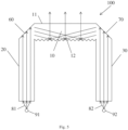
- Fig. 1 is a schematic view showing a light guide assembly 100 according to an embodiment of the present application.
- the light guide assembly 100 includes: a light guide body part 10, a first light incidence part 20 and a second light incidence part 30.
- the light guide body part 10 has a light exit face 11 and a light distribution face 12 opposite to the light exit face 11.
- the first light incidence part 20 has a first end 21 connected to an end of the light guide body part 10 and a second end 22 on which at least one first light guiding unit 40 is provided.
- the first light guiding unit 40 is arranged to receive a first light 81 and direct the first light 81 into the light guide body part 10 via the first light incidence part 20.
- the second light incidence part 30 has a first end 31 connected to the other end of the light guide body part 10 and a second end 32 on which at least one second light guiding unit 50 is provided.
- the second light guiding unit 50 is arranged to receive a second light 82 and direct the second light 82 into the light guide body part 10 via the second light incidence part 30.
- the light distribution face 12 is arranged to reflect the first light 81 directed into the light guide body part 10 via the first light incidence part 20 and/or the second light 82 directed into the light guide body part 10 via the second light incidence part, towards the light exit face 11.
- light guide in the embodiment of the present application may be understood as an optical component that can direct a light by internally total reflection in its interior (for example, the light is directed to an output from an input).
- the light guide assembly as described in the above embodiment may receive and direct two beams of incident lights by two light incidence parts simultaneously.
- the two beams of incident lights may be a same light, or may be different lights from each other (for example, having different colors or different intensities of illumination from each other, and so on).
- the light guide assembly may have more uniform exit light.
- the light guide body part may give an effect of one beam or a mixture effect of the two beams as required. It may improve diversification of the illumination effects.
- the first light incidence part 20 and/or the second light incidence part 30 may be at a certain angle, for example an angle between 70 degrees and 180 degrees such as 90 degrees, relative to the light guide body part 10. It provides a plurality of selections for an incident direction of the incident light.
- the angle is 90 degrees
- the incident direction of the light is substantially identical to the direction in which the light exits from the light exit face 11.
- the light guide assembly 100 is provided with a first reflective guiding face 60 at a position where the light guide body part 10 is connected to the first light incidence part 20. And the first reflective guiding face 60 is arranged to receive the first light 81 from the first light incidence part 20 and reflect all or part of it towards the light distribution face 12.
- the first reflective guiding face 60 may be arranged such that the light from the first light incidence part 20 may be redirected when it enters the light guide body part 10. In this way, the light may have a different main travel direction in the first light incidence part 20, with respect to the main travel direction in the light guide body part 10.
- the first light incidence part 20 and the light guide body part 10 may extend in different directions from each other, that is, a certain angle may be formed between them. It provides more selections for structure design of the light guide assembly.
- the light guide assembly 100 may also be provided with a second reflective guiding face 70 at the position where the light guide body part 10 is connected to the second light incidence part 30.
- the second reflective guiding face 30 is arranged to receive the second light 82 from the second light incidence part 30 and reflect all or part of it towards the light distribution face 12.
- the first reflective guiding face 60 and/or the second reflective guiding face 70 may be total reflection face(s), which may improve optical reflection efficiency.
- the first reflective guiding face 60 may be a portion of the first light incidence part 20 or a portion of the light guide body part 10.
- the second reflective guiding face 70 may be a portion of the second light incidence part 30 or a portion of the light guide body part 10.
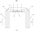
- the first reflective guiding face 60 is substantially perpendicular to an angle-bisecting line of an angle formed by an incidence axis direction (indicated by X1 shown in Fig. 3 ) of the first light 81 incident to the first light incidence part 20 relative to the light exit face 11, for example, the angle between the first reflective guiding face 60 and the angle-bisecting line is between 80 degrees and 100 degrees, such as 90 degrees; and/or the second reflective guiding face 70 is substantially perpendicular to an angle-bisecting line of an angle formed by an incidence axis direction (indicated by X2 shown in Fig.
- the angle between the second reflective guiding face 70 and the angle-bisecting line is between 80 degrees and 100 degrees, such as 90 degrees.
- Such arrangement may correctly direct the first light 81 incident into the first light incidence part 20 and/or the second light 82 incident into the second light incidence part 30 to a proper position in the light guide body part 10.
- Fig. 3 only schematically shows a general direction along which the light travels in the light guide assembly 100, but it does not mean that all of light must travel along the shown direction.
- the light may have a certain angle of divergence in the first light incidence portion 20, the second light incidence portion 30 and the light guide body part 10.
- the light distribution face 12 may be provided with a prism array arrangement, as shown in Fig. 3 .
- the prism array arrangement may have a light diffusion effect, such that the light exiting from the light exit face 11 becomes more uniform.
- the light distribution face 12 may also be used to change the distribution of light intensity. For example, if it is desired that the light exiting from the light exit face 11 has a certain pattern distribution, the light distribution face 12 may be formed with corresponding pattern thereon to impart the pattern to the light passing by the light distribution face 12.
- the light distribution face 12 may also have other light distribution arrangements known in the art to achieve a desired light distribution effect.
- the first light 81 and the second light 82 may have different colors from each other. In this way, the color of the light exiting from the light exit face 11 of the light guide body part 10 may be adjusted by controlling the inputted first light and second light. It may improve the convenience for adjusting the color of the outputted light.
- the first light incidence part 20, the second light incidence part 30 and the light guide body part 10 may be integrally formed. It may simplify the process for producing the assembly. And it may also improve optical efficiency because no interfaces between optical media are provided between respective portions of the assembly.
- the exemplary structures of the first light guiding unit 40 and the second light guiding unit 50 will be explained below.
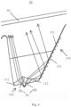
- the first light guiding unit 40 includes: a light incidence side 110 arranged to receive an incident light (such as the first light 81); and a reflective side 130 on which a reflective face 131 is arranged.
- the reflective face 131 is arranged to reflect at least part of the light from the light incidence side 110 towards the light guide body part 10 (for example towards the first reflective guiding face 60).
- the light incidence side 110 is provided with a first incidence face 111 and a second incidence face 112.
- the first incidence face 111 and the second incidence face 112 are arranged to receive a first part 181 of the incident light and a second part 182 of the incident light respectively and to collimate the first part 181 of the incident light and the second part 182 of the incident light in a plane along a first direction respectively.
- the first incidence face 111 and the second incidence face 112 have curve shapes.
- the second incidence face 112 is arranged to direct the second part 182 of the incident light corresponding to it towards the reflective face 131 on the reflective side 130. It should be noted that, in the example shown in Fig. 4 , it is the second incidence face 112 that directs the second part 182 of the incident light corresponding to it towards the reflective face 131 on the reflective side 130.
- the first incidence face 111 may also be arranged to direct the first part 181 of the incident light corresponding to it towards the reflective face 131 on the reflective side 130.
- the first incidence face 111 and the second incidence face 112 collimate the first part 181 of the incident light and the second part 182 of the incident light in a plane along the first direction (i.e., the direction perpendicular to the page in the example shown in Fig. 4 ) respectively.
- the first part 181 of the incident light and the second part 182 of the incident light are both converged into the first light guiding unit 40 in the first direction, so as to reduce the optical loss of the incident light.
- the first guiding unit 40 is in a form of sheet.
- the above structure may prevent or reduce the incident light escaping from the top face and bottom face of the first light guiding unit 40 while being converged towards the light guide body part 10, so as to improve the optical efficiency and to enhance contrast.
- the first incidence face 111 and the second incidence face 112 both have a shape in form of a cross section of convex lens in the plane along the first direction.
- the term "collimate” or “collimation” in the present application does not mean the collimated light must be parallel completely, but the first incidence face 111 and the second incidence face 112 have positive focal powers in the plane along the first direction and thus can at least converge the incident light passing through it to contract the divergent direction of the incident light.
- the extent in which the incident light is converged may be determined in accordance with the specific design requirements (for example, the thickness of the first light guiding unit 40 in the first direction).
- the incident light 180 may be received as large as possible, such that the incident light 180 diffuses uniformly in the first light guiding unit 40.
- the arrangement of the reflective face 131 may change the exit direction of the incident light from the first incidence face 111 and the second incidence face 112. In this way, not only uniform diffusion of the incident light in the first light guiding unit 40 may be ensured, but also the incident light can exit along a desired (for example substantially identical) direction whether it is incident from the first incidence face 111 or the second incidence face 112.
- the first incidence face 111 and the second incidence face 112 may adjoin with each other and have different light guiding directions from each other.
- Two incidence faces having two different light guiding directions from each other are provided on the light incidence side 110, which may add the flexibility of design for the range of the diffusion angle of the light in the first light guiding unit 40. That is, the light is allowed to diffuse uniformly in a relatively large range of angle in the first light guiding unit 40.
- the first incidence face 111 is arranged to direct the first part 181 of the incident light towards the light guide body part 10 and the second incidence face 112 is arranged to direct the second part 182 of the incident light towards the reflective face 131 on the reflective side 130.
- the first incidence face 111 and the second incidence face 112 may direct the first part 181 of the incident light and the second part 182 of the incident light towards different directions respectively, the first part 181 of the incident light and the second part 182 of the incident light may exit in a substantially same direction finally and have uniform exiting intensity due to effects of the reflective face 131.
- the second incidence face 112 may also direct the second part 182 of the incident light towards the light guide body part 10 and the first incidence face 111 may direct the first part 181 of the incident light towards the reflective face 131 on the reflective side 130.
- the shapes of the first incidence face 111 and the second incidence face 112 may be designed depending on a desired light deflection direction.
- An example for calculating the shape of the first incidence face 111 is given.
- the angle by which the first incidence face 111 needs to deflect the first part 182 of the incident light may be determined depending on the desired uniformity of the exit light.
- the shape of the first incidence face 111 may be designed as an irregular curve surface, that is, respective light deflection angles may be independent at each point of the first incidence face 111. It may provide freedom as large as possible for optical design, so as to achieve better light uniformity.
- the first incidence face 111 may be divided into several units (such as small blocks) which have independent light deflection angles from each other, on other words, the first incidence face 111 may be considered to be formed by splicing a plurality of such units.
- the incident direction of the light and the direction in which the light leaves the first incidence face 111 may be set on the basis of the design target of light uniformity and optical principles (such as reflection law, refraction law).
- the first incidence face 111 may be cut along a certain direction (for example, in the above first direction, or the horizontal direction, vertical direction) to obtain a curve profile.
- the plane in which the curve profile is placed may be defined as X-Y plane and the curve profile may be approximated by connecting a plurality of straight line section units one by one.
- the length of each of the straight line section units in X direction (or called as X step length) may be defined as STEP X .
- the length of each of the straight line section units in Y direction (or called as Y step length) may be defined as STEP Y .
- the ratio of STEP Y to STEP X is called as a slope SLP of the straight line section unit. If the slope of each of the straight line section units is determined, the shape of the curve profile may also be determined. If each of the straight line section units is sufficiently small, the shape of the curve profile may become substantially smooth.
- the above X step length and Y step length may be selected on the basis of the calculation accuracy, for example, may be 0.1mm, 0.05mm, 0.01mm or the like.
- the slope of the straight line section may be determined by optical laws.
- SLP is the slope of the straight line section unit
- tan represents a tangent function
- arctan represents an inverse tangent function
- n is a refractive index of the light guiding unit
- ⁇ is an incident angle of the first part of the incident light onto the straight line section
- ⁇ is a deflection angle of the incident light passing through the straight line section unit (i.e., the angle between the incident angle and the refraction angle)
- the units of ⁇ and ⁇ are degrees (°).
- the shape of the above curve profile may be determined by solving the slope of the respective straight line section units one by one. In same way, the shape of the curve profile obtained by cutting the first incidence face 111 along another direction may also be solved. From the shapes of the plurality of curve profiles obtained by cutting the first incidence face 111 in a plurality of directions, the shape of the entire first incidence face 111 may further be solved.
- the divisions of the above straight line section units and selection of the curve profiles both may be set on the basis of the design precision and requirements.
- the above only gives an example of calculating a shape of the first incidence face 111.
- the calculation process may need to adjust parameters repeatedly on the basis of the design of light distribution for calculation.
- the shape of the second incidence face 112 may be calculated in the same way as the described above. The details will be omitted below.
- the first part 181 or the second part 182 of the incident light directed onto the reflective face 131 on the reflective side 130 may have an angle of divergence between 10 degrees to 70 degrees, for example, 30 degrees, 40 degrees.
- the reflective face 131 on the reflective side 130 may be a total reflection face. It may efficiently improve the optical efficiency of the light traveling in the first light guiding unit 40.
- the shape and relative position of the reflective face 131 and the second incident face 112(or the first incident face 111) may be arranged to allow the light from the second incident face 112 (or the first incident face 111) to meet total reflection condition at the reflective face 131.
- the reflective face 131 on the reflective side 130 may be provided with optical stripes 132 thereon.
- the optical stripes 132 may increase the diffusion of the light in the first light guiding unit 40 to improve the uniformity in distribution of the exit light.
- Fig. 4 only shows the reflective face 131 arranged on one reflective side 130 of the first light guiding unit 40
- the first light guiding unit 40 may also be provided with the reflective face on another side opposite to the reflective side 130, such that the incident lights from the first incidence face 111 and the second incidence face 112 are respectively directed towards the light guide body part 10 through the reflection of the reflective faces on both sides.
- Such double reflective face arrangement may further improve the diffusion range and uniformity of the light in the first light guiding unit 40.
- the first incidence face 111 and/or the second incidence face 112 have(has) a convex shape in a cross section in a plane perpendicular to the plane along the first direction (for example, in the example shown in Fig. 1 , it is a plane parallel to the page).
- the first incidence face 111 and/or the second incidence face 112 not only have(has) collimation effects on the incident light in the plane along the first direction, but also have convergent effects on the light in the plane perpendicular to the plane along the first direction to some extent. It may provide more flexibility for the design of the first light guiding unit 40.
- the curve shapes of the first incidence face 111 and the second incidence face 112 are not limited by this. They may be calculated out on the basis of the incident direction of the incident light on the first light guiding unit 40 and the desired exit direction and range of the exit light.
- the curve shapes of the first incidence face 111 and the second incidence face 112 may be formed by smooth curve surfaces, or may be spliced by a plurality of plane sections or curve sections. The latter may reduce the difficulty of production.
- the first direction may be the thickness direction of the first light guiding unit 40, for example, the direction perpendicular to the page in Fig. 1 .
- Such design will be in particular advantageous if the first light guiding unit 40 has a shape in a form of sheet.
- the exit direction of the exit light may be deflected at any desired angle with respect to the direction of the incident light while the incident light is diffused uniformly.
- the exit direction of the first light guiding unit 40 may be at an angle not greater than 75 degrees with respect to the axis direction of the incident light. It provides flexibility for arrangements of a light source or other optical elements in the lighting and/or signaling apparatus.
- a plurality of first light guiding units 40 may be arranged in parallel on the first light incidence part 20.
- one first light guiding unit 40 may be provided for each light source (for example a light emitting diode).
- the first light guiding unit 40 may allow the light emitted from the corresponding light source 201 to diffuse uniformly in it. Good light uniformity will also be maintained even at the position in which two adjacent first light guiding units 40 are connected.
- All of the above exemplary embodiments for the first light guiding unit 40 may be applicable for the second light guiding unit 50. That is, at least one of the first light guiding unit 40 and the second light guiding unit 50 may have the exemplary structure as described in any one of the above embodiments.
- first light guiding units 40 and the second guiding units 50 are given in the above, the present application is not limited to this. They may also be implemented by other structures for directing light known in the art as long as it can achieve function of directing the first light and the second light to the light guide body part 10.
- the light guide body part 10, the first light incidence part 20 or the second light incidence part 30 may be in a form of a planar light wave guide.
- the planar light wave guide is a light guide. Its thickness is smaller than its length and width. It may be bent and have a given curvature.
- the light wave guide has two large faces separated by a perimeter. The perimeter defines the thickness of the planar light wave guide. The thickness may be constant, or may be variable. For example, the thickness is reduced gradually from one end to the other end of the planar light wave guide.
- the surface in which the planar light wave guide extends may form a guiding surface for defining the light traveling by internally total reflection. However, this is only by way of examples. The embodiments of the present application are not limited to this.
- An embodiment of the present application also provides a lighting and/or signaling apparatus, as shown in Fig. 5 . It includes: a first light source 91 arranged to emit a first light 81; a second light source 92 arranged to emit a second light 82; and the light guide assembly 100 as described in any one of the above embodiments.
- the first light incidence part 20 and the second incidence part 30 of the light guide assembly 100 are arranged to receive the first light 81 and the second light 82 respectively.
- the first light source 91 includes an array of first light emitting diodes, and the second end 22 of the first light incidence part 20 is provided with an array of the first light guiding units 40 which is arranged corresponding to the array of first light emitting diodes; and/or the second light source 92 includes an array of second light emitting diodes, and the second end 32 of the second light incidence part 30 is provided with an array of the second light guiding units 50 which is arranged corresponding to the array of second light emitting diodes. That is, each light emitting diode in the array of first light emitting diodes and the array of second light emitting diodes corresponds to a first light guiding unit or a second light guiding unit.
- the power of the light emitting diodes in the array of first light emitting diodes and the array of second light emitting diodes may be lower with respect to the case that only one incidence part is used.
- Such arrangement of double light emitting diode arrays may also provide more flexibility for adjustment of the output intensity of the lighting and/or signaling apparatus.
- the lighting and/or signaling apparatus in accordance with the present application may be used for lighting and signaling in vehicles, or may be used widely for other lighting and/or signaling applications, for example, an electric torch, a reflective plate for photograph.
Landscapes
- Engineering & Computer Science (AREA)
- Physics & Mathematics (AREA)
- General Engineering & Computer Science (AREA)
- Optics & Photonics (AREA)
- General Physics & Mathematics (AREA)
- Microelectronics & Electronic Packaging (AREA)
- Planar Illumination Modules (AREA)
- Non-Portable Lighting Devices Or Systems Thereof (AREA)
Claims (11)
- Lichtleiteranordnung (100), die Folgendes umfasst:einen Lichtleiterkörperteil (10) mit einer Lichtaustrittsfläche (11) und einer Lichtverteilungsfläche 12 gegenüber der Lichtaustrittsfläche (11);einen ersten Lichteinfallsteil (20) mit einem ersten Ende (21), verbunden mit einem Ende des Lichtleiterkörperteils (10) und einem zweiten Ende (22), an dem zumindest eine erste Lichtleitereinheit (40) bereitgestellt ist, wobei die erste Lichtleitereinheit (40) dazu angeordnet ist, ein erstes Licht (81) zu empfangen und das erste Licht (81) über den ersten Lichteinfallsteil (20) in den Lichtleiterkörperteil (10) zu leiten;einen zweiten Lichteinfallsteil (30) mit einem ersten Ende (31), verbunden mit dem anderen Ende des Lichtleiterkörperteils (10) und einem zweiten Ende (32), an dem zumindest eine zweite Lichtleitereinheit (50) bereitgestellt ist, wobei die zweite Lichtleitereinheit (50) dazu angeordnet ist, ein zweites Licht (82) zu empfangen und das zweite Licht (82) über den zweiten Lichteinfallsteil (50) in den Lichtleiterkörperteil (10) zu leiten,wobei die Lichtverteilungsfläche (12) angeordnet ist zum Reflektieren des ersten Lichts (81), das über den ersten Lichteinfallsteil (40) in den Lichtleiterkörperteil (10) geleitet wird, und/oder des zweiten Lichts (81), das über den zweiten Lichteinfallsteil (50) in den Lichtleiterkörperteil (10) geleitet wird, in Richtung der Lichtaustrittsfläche (11),wobei zumindest eine aus der ersten Lichtleitereinheit (40) und der zweiten Lichtleitereinheit (50) Folgendes umfasst:eine Lichteinfallsseite (110), angeordnet zum Empfangen eines einfallenden Lichts;eine reflektierende Seite (130), auf der eine reflektierende Fläche (131) angeordnet ist, wobei die reflektierende Fläche (131) angeordnet ist zum Reflektieren zumindest eines Teils des Lichts von der Lichteinfallsseite (110) in Richtung des Lichtleiterkörperteils (10),wobei die Lichteinfallsseite (110) mit einer ersten Einfallsfläche (111) und einer zweiten Einfallsfläche (112) versehen sind, die angeordnet sind zum Empfangen eines ersten Teils (181) des einfallenden Lichts bzw. eines zweiten Teils (182) des einfallenden Lichts und zum Bündeln des ersten Teils (181) des einfallenden Lichts bzw. des zweiten Teils (182) des einfallenden Lichts in einer Ebene entlang einer ersten Richtung, undwobei eine aus der ersten Einfallsfläche (111) und der zweiten Einfallsfläche (112) angeordnet ist zum Leiten des ersten Teils (181) oder des zweiten Teils (182) des entsprechenden einfallenden Lichts in Richtung der reflektierenden Fläche (131) auf der reflektierenden Seite (130);dadurch gekennzeichnet, dass die erste Einfallsfläche (111) und die zweite Einfallsfläche (112) Kurvenformen aufweisen, und dass die Form der ersten Einfallsfläche (111) als eine unregelmäßige Kurvenoberfläche ausgestaltet ist, das heißt, dass entsprechende Lichtablenkwinkel an jedem Punkt der ersten Einfallsfläche (111) unabhängig sind.
- Lichtleiteranordnung (100) nach Anspruch 1, wobei der erste Lichteinfallsteil (20) und/oder der zweite Lichteinfallsteil (30) bei einem Winkel zwischen 70 Grad und 180 Grad relativ zum Lichtleiterkörperteil (10) sind/ist.
- Lichtleiteranordnung (100) nach Anspruch 1, wobei der erste Lichteinfallsteil (20) und/oder der zweite Lichteinfallsteil (30) bei einem Winkel von 90 Grad relativ zum Lichtleiterkörperteil (10) sind/ist.
- Lichtleiteranordnung (100) nach Anspruch 1, wobei die Lichtleiteranordnung (100) an der Position, wo der Lichtleiterkörperteil (10) mit dem ersten Lichteinfallsteil (20) verbunden ist, mit einer ersten reflektierenden Leiterfläche (60) versehen ist, wobei die erste reflektierende Leiterfläche (60) angeordnet ist zum Empfangen des ersten Lichts (81) vom ersten Lichteinfallsteil (20) und Reflektieren von allem oder einem Teil davon in Richtung der Lichtverteilungsfläche (12); und/oder
wobei die Lichtleiteranordnung (100) an der Position, wo der Lichtleiterkörperteil (10) mit dem zweiten Lichteinfallsteil (30) verbunden ist, mit einer zweiten reflektierenden Leiterfläche (70) versehen ist, wobei die zweite reflektierende Leiterfläche (70) angeordnet ist zum Empfangen des zweiten Lichts (82) vom zweiten Lichteinfallsteil (30) und Reflektieren von allem oder einem Teil davon in Richtung der Lichtverteilungsfläche (12) . - Lichtleiteranordnung (100) nach Anspruch 4, wobei die erste reflektierende Leiterfläche (60) ein Teil des ersten Lichteinfallsteils (20) oder ein Teil des Lichtleiterkörperteils (10) ist; und/oder wobei die zweite reflektierende Leiterfläche (70) ein Teil des zweiten Lichteinfallsteils (30) oder ein Teil des Lichtleiterkörperteils (10) ist.
- Lichtleiteranordnung (100) nach Anspruch 4, wobei die erste reflektierende Leiterfläche (60) im Wesentlichen senkrecht zu einer winkelhalbierenden Linie eines Winkels ist, der durch eine Einfallsachsenrichtung (X1) des ersten Lichts (81), das auf dem ersten Lichteinfallsteil (20) einfällt, relativ zur Lichtaustrittsfläche (11) gebildet ist; und/oder wobei die zweite reflektierende Leiterfläche (70) im Wesentlichen senkrecht zu einer winkelhalbierenden Linie eines Winkels ist, der durch eine Einfallsachsenrichtung (X2) des zweiten Lichts (82), das auf dem zweiten Lichteinfallsteil (30) einfällt, relativ zur Lichtaustrittsfläche (12) gebildet ist.
- Lichtleiteranordnung (100) nach einem der Ansprüche 1-6, wobei die Lichtverteilungsfläche (12) mit einer Prismenfeldanordnung versehen ist.
- Lichtleiteranordnung nach einem der Ansprüche 1-6, wobei das erste Licht (81) und das zweite Licht (82) voneinander verschiedene Farben aufweisen.
- Lichtleiteranordnung (100) nach einem der Ansprüche 1-6, wobei der erste Lichteinfallsteil (20), der zweite Lichteinfallsteil (30) und der Lichtleiterkörperteil (10) integral ausgebildet sind.
- Beleuchtungs- und/oder Signalisierungsvorrichtung, die Folgendes umfasst:eine erste Lichtquelle (91), angeordnet zum Emittieren eines ersten Lichts (81);eine zweite Lichtquelle (92), angeordnet zum Emittieren eines zweiten Lichts (82);eine Lichtleiteranordnung nach einem Ansprüche 1-9.
- Beleuchtungs- und/oder Signalisierungsvorrichtung nach Anspruch 10, wobei die erste Lichtquelle (91) ein Feld von ersten Leuchtdioden umfasst und das zweite Ende (22) des ersten Lichteinfallsteils (20) mit einem Feld der ersten Lichtleitereinheiten (40) versehen ist, das entsprechend dem Feld von ersten Leuchtdioden angeordnet ist; und/oder die zweite Lichtquelle (92) ein Feld von zweiten Leuchtdioden umfasst und das zweite Ende des zweiten Lichteinfallsteils (30) mit einem Feld der zweiten Lichtleitereinheiten (50) versehen ist, das entsprechend dem Feld von zweiten Leuchtdioden angeordnet ist.
Applications Claiming Priority (1)
| Application Number | Priority Date | Filing Date | Title |
|---|---|---|---|
| CN201610093602.5A CN107101178B (zh) | 2016-02-19 | 2016-02-19 | 光导组件以及照明和/或信号指示装置 |
Publications (2)
| Publication Number | Publication Date |
|---|---|
| EP3208535A1 EP3208535A1 (de) | 2017-08-23 |
| EP3208535B1 true EP3208535B1 (de) | 2023-09-06 |
Family
ID=58094242
Family Applications (1)
| Application Number | Title | Priority Date | Filing Date |
|---|---|---|---|
| EP17156605.2A Active EP3208535B1 (de) | 2016-02-19 | 2017-02-17 | Lichtleiteranordnung und beleuchtungs- und/oder signalisierungsvorrichtung |
Country Status (3)
| Country | Link |
|---|---|
| US (1) | US10584843B2 (de) |
| EP (1) | EP3208535B1 (de) |
| CN (1) | CN107101178B (de) |
Families Citing this family (17)
| Publication number | Priority date | Publication date | Assignee | Title |
|---|---|---|---|---|
| US10088118B2 (en) * | 2016-08-30 | 2018-10-02 | HELLA GmbH & Co. KGaA | Light emitting area extender |
| CN109506205B (zh) * | 2017-09-14 | 2022-08-05 | 法雷奥照明湖北技术中心有限公司 | 光束调整装置、车灯与机动车辆 |
| CN107893963B (zh) * | 2017-11-15 | 2024-05-03 | 华域视觉科技(上海)有限公司 | 车辆用灯具光学系统 |
| JP7042616B2 (ja) * | 2017-12-28 | 2022-03-28 | スタンレー電気株式会社 | 車両用灯具 |
| CN110207070B (zh) * | 2018-02-28 | 2025-01-28 | 法雷奥市光(中国)车灯有限公司 | 光导部件、车灯和机动车辆 |
| CN110657399B (zh) * | 2018-06-29 | 2025-11-04 | 法雷奥市光(中国)车灯有限公司 | 配光构件、照明或信号指示装置和机动车辆 |
| FR3087519B1 (fr) * | 2018-10-17 | 2022-05-06 | Psa Automobiles Sa | Module lumineux bi-fonction pour bloc optique d’eclairage et/ou de signalisation de vehicule |
| DE102018129596A1 (de) * | 2018-11-23 | 2020-05-28 | HELLA GmbH & Co. KGaA | Beleuchtungsvorrichtung für Fahrzeuge |
| CN112289205B (zh) * | 2019-07-12 | 2025-11-07 | 华为技术有限公司 | 炫彩显示组件及电子设备 |
| CN110608414A (zh) * | 2019-09-23 | 2019-12-24 | 华域视觉科技(上海)有限公司 | 信号灯功能复用式分叉聚光器以及汽车 |
| CN110630978A (zh) * | 2019-09-23 | 2019-12-31 | 华域视觉科技(上海)有限公司 | 信号灯功能复用式复合反射镜装置以及汽车 |
| CN217382775U (zh) * | 2021-12-30 | 2022-09-06 | 市光法雷奥(佛山)汽车照明系统有限公司 | 准直器、照明装置和机动车辆 |
| CN114724470B (zh) * | 2022-04-08 | 2023-07-14 | 深圳市思坦科技有限公司 | 微型led芯片阵列片及微型led显示模组 |
| US12510220B2 (en) * | 2022-04-20 | 2025-12-30 | Hasco Vision Technology Co., Ltd. | Optical element, vehicle light module, vehicle light and vehicle |
| CN114909636A (zh) * | 2022-04-29 | 2022-08-16 | 马瑞利汽车零部件(芜湖)有限公司 | 带折角消除光线亮斑的光导厚壁件光学系统及车灯 |
| TWI861740B (zh) * | 2023-02-23 | 2024-11-11 | 瑞軒科技股份有限公司 | 柱狀發光構件及具有柱狀發光構件之發光耳機架 |
| CN121576564A (zh) * | 2023-08-30 | 2026-02-27 | 奥豪斯仪器(常州)有限公司 | 光照结构及电子衡器 |
Family Cites Families (14)
| Publication number | Priority date | Publication date | Assignee | Title |
|---|---|---|---|---|
| FR2472135A1 (fr) * | 1979-12-20 | 1981-06-26 | Cibie Projecteurs | Projecteur, notamment pour vehicules automobiles |
| US5005108A (en) * | 1989-02-10 | 1991-04-02 | Lumitex, Inc. | Thin panel illuminator |
| US5434754A (en) * | 1993-12-27 | 1995-07-18 | Ford Motor Company | Light manifold |
| US5515244A (en) * | 1995-04-03 | 1996-05-07 | Apple Computer, Inc. | Light-transmitting pipe |
| US6497505B2 (en) * | 2001-03-22 | 2002-12-24 | Visteon Global Tech., Inc. | Light manifold assembly |
| JP2005505796A (ja) * | 2001-10-10 | 2005-02-24 | シーメンス アクチエンゲゼルシヤフト | ディスプレイ装置 |
| FR2888917B1 (fr) * | 2005-07-21 | 2009-11-20 | Valeo Vision | Dispositif d'eclairage ou de signalisation, notamment pour vehicule automobile |
| FR2901345B1 (fr) * | 2006-05-16 | 2008-07-18 | Valeo Vision Sa | Dispositif d'eclairage et/ou de signalisation pour vehicule automobile. |
| JP2008277006A (ja) | 2007-04-26 | 2008-11-13 | Rohm Co Ltd | 線状光源装置およびこれを備える画像読み取り装置 |
| US9337373B2 (en) * | 2007-05-01 | 2016-05-10 | Morgan Solar Inc. | Light-guide solar module, method of fabrication thereof, and panel made therefrom |
| CZ306888B6 (cs) * | 2010-08-06 | 2017-08-30 | Varroc Lighting Systems, s.r.o. | Světlovodicí modul |
| FR3003928A1 (fr) | 2013-03-27 | 2014-10-03 | Valeo Vision | Dispositif d'eclairage ou de signalisation pour vehicule automobile |
| DE102014102496B4 (de) * | 2014-02-26 | 2026-04-23 | HELLA GmbH & Co. KGaA | Beleuchtungsvorrichtung für Fahrzeuge |
| JP2015179579A (ja) | 2014-03-18 | 2015-10-08 | 株式会社東芝 | 導光体および照明装置 |
-
2016
- 2016-02-19 CN CN201610093602.5A patent/CN107101178B/zh active Active
-
2017
- 2017-02-15 US US15/433,287 patent/US10584843B2/en active Active
- 2017-02-17 EP EP17156605.2A patent/EP3208535B1/de active Active
Also Published As
| Publication number | Publication date |
|---|---|
| CN107101178B (zh) | 2020-01-14 |
| US20170241615A1 (en) | 2017-08-24 |
| CN107101178A (zh) | 2017-08-29 |
| US10584843B2 (en) | 2020-03-10 |
| EP3208535A1 (de) | 2017-08-23 |
Similar Documents
| Publication | Publication Date | Title |
|---|---|---|
| EP3208535B1 (de) | Lichtleiteranordnung und beleuchtungs- und/oder signalisierungsvorrichtung | |
| EP3456587B1 (de) | Lichtstrahleinstellvorrichtung, fahrzeuglampe und kraftfahrzeug | |
| US11828432B2 (en) | Light-guiding assembly, vehicle lamp, and vehicle | |
| US10761254B2 (en) | Light-guiding optical system | |
| EP3018401B1 (de) | Fahrzeugbeleuchtungsvorrichtung | |
| EP4073424B1 (de) | Leuchte mit lichtleiter für ein fahrzeug | |
| CN110296372B (zh) | 一种光导、车灯及车辆 | |
| US10767827B2 (en) | LED lighting device | |
| US8465180B2 (en) | Optical element for asymmetric light distribution | |
| US8475019B2 (en) | Hotspot cutoff D-optic | |
| EP3207307B1 (de) | Lichtleitende vorrichtung und fahrzeuglampe | |
| CN108302470B (zh) | 光图案化装置与车灯 | |
| CN113217871B (zh) | 特别是具有led的用于车辆的照明装置 | |
| US10042111B2 (en) | Light guiding unit, light guiding device, and lighting and/or signal indicating device | |
| EP3480518B1 (de) | Lichtausgangsstruktur und lichtausgangssystem damit | |
| JP7048897B2 (ja) | 光学部材、光源装置及び照射システム | |
| JP2023082689A (ja) | ライトガイド | |
| US10627560B2 (en) | Optical system for lighting equipment, especially for a signal lamp for motor vehicles | |
| JP2016162754A (ja) | 車両用発光装置 | |
| US10738959B2 (en) | Vehicular lamp fitting | |
| JP2019179648A (ja) | 車両用灯具 | |
| WO2022190602A1 (ja) | 照明装置 | |
| CN111380028A (zh) | 光学结构,照明方法及相应的车灯和车辆 | |
| WO2018207380A1 (ja) | 光学素子および光学系装置 | |
| JP2019185886A (ja) | 面状発光モジュール、及び照明装置 |
Legal Events
| Date | Code | Title | Description |
|---|---|---|---|
| PUAI | Public reference made under article 153(3) epc to a published international application that has entered the european phase |
Free format text: ORIGINAL CODE: 0009012 |
|
| STAA | Information on the status of an ep patent application or granted ep patent |
Free format text: STATUS: THE APPLICATION HAS BEEN PUBLISHED |
|
| AK | Designated contracting states |
Kind code of ref document: A1 Designated state(s): AL AT BE BG CH CY CZ DE DK EE ES FI FR GB GR HR HU IE IS IT LI LT LU LV MC MK MT NL NO PL PT RO RS SE SI SK SM TR |
|
| AX | Request for extension of the european patent |
Extension state: BA ME |
|
| STAA | Information on the status of an ep patent application or granted ep patent |
Free format text: STATUS: REQUEST FOR EXAMINATION WAS MADE |
|
| 17P | Request for examination filed |
Effective date: 20180625 |
|
| RBV | Designated contracting states (corrected) |
Designated state(s): AL AT BE BG CH CY CZ DE DK EE ES FI FR GB GR HR HU IE IS IT LI LT LU LV MC MK MT NL NO PL PT RO RS SE SI SK SM TR |
|
| STAA | Information on the status of an ep patent application or granted ep patent |
Free format text: STATUS: EXAMINATION IS IN PROGRESS |
|
| 17Q | First examination report despatched |
Effective date: 20210420 |
|
| GRAP | Despatch of communication of intention to grant a patent |
Free format text: ORIGINAL CODE: EPIDOSNIGR1 |
|
| STAA | Information on the status of an ep patent application or granted ep patent |
Free format text: STATUS: GRANT OF PATENT IS INTENDED |
|
| RIC1 | Information provided on ipc code assigned before grant |
Ipc: F21Y 115/10 20160101ALN20230308BHEP Ipc: F21S 10/00 20060101ALN20230308BHEP Ipc: F21S 43/249 20180101ALI20230308BHEP Ipc: F21S 43/241 20180101ALI20230308BHEP Ipc: F21S 43/14 20180101ALI20230308BHEP Ipc: F21V 8/00 20060101AFI20230308BHEP |
|
| RIC1 | Information provided on ipc code assigned before grant |
Ipc: F21Y 115/10 20160101ALN20230314BHEP Ipc: F21S 10/00 20060101ALN20230314BHEP Ipc: F21S 43/249 20180101ALI20230314BHEP Ipc: F21S 43/241 20180101ALI20230314BHEP Ipc: F21S 43/14 20180101ALI20230314BHEP Ipc: F21V 8/00 20060101AFI20230314BHEP |
|
| INTG | Intention to grant announced |
Effective date: 20230405 |
|
| P01 | Opt-out of the competence of the unified patent court (upc) registered |
Effective date: 20230602 |
|
| GRAS | Grant fee paid |
Free format text: ORIGINAL CODE: EPIDOSNIGR3 |
|
| GRAA | (expected) grant |
Free format text: ORIGINAL CODE: 0009210 |
|
| STAA | Information on the status of an ep patent application or granted ep patent |
Free format text: STATUS: THE PATENT HAS BEEN GRANTED |
|
| AK | Designated contracting states |
Kind code of ref document: B1 Designated state(s): AL AT BE BG CH CY CZ DE DK EE ES FI FR GB GR HR HU IE IS IT LI LT LU LV MC MK MT NL NO PL PT RO RS SE SI SK SM TR |
|
| REG | Reference to a national code |
Ref country code: GB Ref legal event code: FG4D |
|
| REG | Reference to a national code |
Ref country code: CH Ref legal event code: EP |
|
| REG | Reference to a national code |
Ref country code: IE Ref legal event code: FG4D |
|
| REG | Reference to a national code |
Ref country code: DE Ref legal event code: R096 Ref document number: 602017073665 Country of ref document: DE |
|
| REG | Reference to a national code |
Ref country code: LT Ref legal event code: MG9D |
|
| REG | Reference to a national code |
Ref country code: NL Ref legal event code: MP Effective date: 20230906 |
|
| PG25 | Lapsed in a contracting state [announced via postgrant information from national office to epo] |
Ref country code: GR Free format text: LAPSE BECAUSE OF FAILURE TO SUBMIT A TRANSLATION OF THE DESCRIPTION OR TO PAY THE FEE WITHIN THE PRESCRIBED TIME-LIMIT Effective date: 20231207 |
|
| PG25 | Lapsed in a contracting state [announced via postgrant information from national office to epo] |
Ref country code: SE Free format text: LAPSE BECAUSE OF FAILURE TO SUBMIT A TRANSLATION OF THE DESCRIPTION OR TO PAY THE FEE WITHIN THE PRESCRIBED TIME-LIMIT Effective date: 20230906 Ref country code: RS Free format text: LAPSE BECAUSE OF FAILURE TO SUBMIT A TRANSLATION OF THE DESCRIPTION OR TO PAY THE FEE WITHIN THE PRESCRIBED TIME-LIMIT Effective date: 20230906 Ref country code: NO Free format text: LAPSE BECAUSE OF FAILURE TO SUBMIT A TRANSLATION OF THE DESCRIPTION OR TO PAY THE FEE WITHIN THE PRESCRIBED TIME-LIMIT Effective date: 20231206 Ref country code: LV Free format text: LAPSE BECAUSE OF FAILURE TO SUBMIT A TRANSLATION OF THE DESCRIPTION OR TO PAY THE FEE WITHIN THE PRESCRIBED TIME-LIMIT Effective date: 20230906 Ref country code: LT Free format text: LAPSE BECAUSE OF FAILURE TO SUBMIT A TRANSLATION OF THE DESCRIPTION OR TO PAY THE FEE WITHIN THE PRESCRIBED TIME-LIMIT Effective date: 20230906 Ref country code: HR Free format text: LAPSE BECAUSE OF FAILURE TO SUBMIT A TRANSLATION OF THE DESCRIPTION OR TO PAY THE FEE WITHIN THE PRESCRIBED TIME-LIMIT Effective date: 20230906 Ref country code: GR Free format text: LAPSE BECAUSE OF FAILURE TO SUBMIT A TRANSLATION OF THE DESCRIPTION OR TO PAY THE FEE WITHIN THE PRESCRIBED TIME-LIMIT Effective date: 20231207 Ref country code: FI Free format text: LAPSE BECAUSE OF FAILURE TO SUBMIT A TRANSLATION OF THE DESCRIPTION OR TO PAY THE FEE WITHIN THE PRESCRIBED TIME-LIMIT Effective date: 20230906 |
|
| REG | Reference to a national code |
Ref country code: AT Ref legal event code: MK05 Ref document number: 1608983 Country of ref document: AT Kind code of ref document: T Effective date: 20230906 |
|
| PG25 | Lapsed in a contracting state [announced via postgrant information from national office to epo] |
Ref country code: NL Free format text: LAPSE BECAUSE OF FAILURE TO SUBMIT A TRANSLATION OF THE DESCRIPTION OR TO PAY THE FEE WITHIN THE PRESCRIBED TIME-LIMIT Effective date: 20230906 |
|
| PG25 | Lapsed in a contracting state [announced via postgrant information from national office to epo] |
Ref country code: IS Free format text: LAPSE BECAUSE OF FAILURE TO SUBMIT A TRANSLATION OF THE DESCRIPTION OR TO PAY THE FEE WITHIN THE PRESCRIBED TIME-LIMIT Effective date: 20240106 |
|
| PG25 | Lapsed in a contracting state [announced via postgrant information from national office to epo] |
Ref country code: AT Free format text: LAPSE BECAUSE OF FAILURE TO SUBMIT A TRANSLATION OF THE DESCRIPTION OR TO PAY THE FEE WITHIN THE PRESCRIBED TIME-LIMIT Effective date: 20230906 |
|
| PG25 | Lapsed in a contracting state [announced via postgrant information from national office to epo] |
Ref country code: ES Free format text: LAPSE BECAUSE OF FAILURE TO SUBMIT A TRANSLATION OF THE DESCRIPTION OR TO PAY THE FEE WITHIN THE PRESCRIBED TIME-LIMIT Effective date: 20230906 |
|
| PG25 | Lapsed in a contracting state [announced via postgrant information from national office to epo] |
Ref country code: SM Free format text: LAPSE BECAUSE OF FAILURE TO SUBMIT A TRANSLATION OF THE DESCRIPTION OR TO PAY THE FEE WITHIN THE PRESCRIBED TIME-LIMIT Effective date: 20230906 Ref country code: RO Free format text: LAPSE BECAUSE OF FAILURE TO SUBMIT A TRANSLATION OF THE DESCRIPTION OR TO PAY THE FEE WITHIN THE PRESCRIBED TIME-LIMIT Effective date: 20230906 Ref country code: IS Free format text: LAPSE BECAUSE OF FAILURE TO SUBMIT A TRANSLATION OF THE DESCRIPTION OR TO PAY THE FEE WITHIN THE PRESCRIBED TIME-LIMIT Effective date: 20240106 Ref country code: ES Free format text: LAPSE BECAUSE OF FAILURE TO SUBMIT A TRANSLATION OF THE DESCRIPTION OR TO PAY THE FEE WITHIN THE PRESCRIBED TIME-LIMIT Effective date: 20230906 Ref country code: EE Free format text: LAPSE BECAUSE OF FAILURE TO SUBMIT A TRANSLATION OF THE DESCRIPTION OR TO PAY THE FEE WITHIN THE PRESCRIBED TIME-LIMIT Effective date: 20230906 Ref country code: CZ Free format text: LAPSE BECAUSE OF FAILURE TO SUBMIT A TRANSLATION OF THE DESCRIPTION OR TO PAY THE FEE WITHIN THE PRESCRIBED TIME-LIMIT Effective date: 20230906 Ref country code: AT Free format text: LAPSE BECAUSE OF FAILURE TO SUBMIT A TRANSLATION OF THE DESCRIPTION OR TO PAY THE FEE WITHIN THE PRESCRIBED TIME-LIMIT Effective date: 20230906 Ref country code: PT Free format text: LAPSE BECAUSE OF FAILURE TO SUBMIT A TRANSLATION OF THE DESCRIPTION OR TO PAY THE FEE WITHIN THE PRESCRIBED TIME-LIMIT Effective date: 20240108 Ref country code: SK Free format text: LAPSE BECAUSE OF FAILURE TO SUBMIT A TRANSLATION OF THE DESCRIPTION OR TO PAY THE FEE WITHIN THE PRESCRIBED TIME-LIMIT Effective date: 20230906 |
|
| PG25 | Lapsed in a contracting state [announced via postgrant information from national office to epo] |
Ref country code: PL Free format text: LAPSE BECAUSE OF FAILURE TO SUBMIT A TRANSLATION OF THE DESCRIPTION OR TO PAY THE FEE WITHIN THE PRESCRIBED TIME-LIMIT Effective date: 20230906 Ref country code: IT Free format text: LAPSE BECAUSE OF FAILURE TO SUBMIT A TRANSLATION OF THE DESCRIPTION OR TO PAY THE FEE WITHIN THE PRESCRIBED TIME-LIMIT Effective date: 20230906 |
|
| REG | Reference to a national code |
Ref country code: DE Ref legal event code: R097 Ref document number: 602017073665 Country of ref document: DE |
|
| PG25 | Lapsed in a contracting state [announced via postgrant information from national office to epo] |
Ref country code: DK Free format text: LAPSE BECAUSE OF FAILURE TO SUBMIT A TRANSLATION OF THE DESCRIPTION OR TO PAY THE FEE WITHIN THE PRESCRIBED TIME-LIMIT Effective date: 20230906 |
|
| PLBE | No opposition filed within time limit |
Free format text: ORIGINAL CODE: 0009261 |
|
| STAA | Information on the status of an ep patent application or granted ep patent |
Free format text: STATUS: NO OPPOSITION FILED WITHIN TIME LIMIT |
|
| PG25 | Lapsed in a contracting state [announced via postgrant information from national office to epo] |
Ref country code: DK Free format text: LAPSE BECAUSE OF FAILURE TO SUBMIT A TRANSLATION OF THE DESCRIPTION OR TO PAY THE FEE WITHIN THE PRESCRIBED TIME-LIMIT Effective date: 20230906 Ref country code: SI Free format text: LAPSE BECAUSE OF FAILURE TO SUBMIT A TRANSLATION OF THE DESCRIPTION OR TO PAY THE FEE WITHIN THE PRESCRIBED TIME-LIMIT Effective date: 20230906 |
|
| 26N | No opposition filed |
Effective date: 20240607 |
|
| PG25 | Lapsed in a contracting state [announced via postgrant information from national office to epo] |
Ref country code: MC Free format text: LAPSE BECAUSE OF FAILURE TO SUBMIT A TRANSLATION OF THE DESCRIPTION OR TO PAY THE FEE WITHIN THE PRESCRIBED TIME-LIMIT Effective date: 20230906 |
|
| REG | Reference to a national code |
Ref country code: CH Ref legal event code: PL |
|
| PG25 | Lapsed in a contracting state [announced via postgrant information from national office to epo] |
Ref country code: LU Free format text: LAPSE BECAUSE OF NON-PAYMENT OF DUE FEES Effective date: 20240217 |
|
| PG25 | Lapsed in a contracting state [announced via postgrant information from national office to epo] |
Ref country code: CH Free format text: LAPSE BECAUSE OF NON-PAYMENT OF DUE FEES Effective date: 20240229 |
|
| GBPC | Gb: european patent ceased through non-payment of renewal fee |
Effective date: 20240217 |
|
| PG25 | Lapsed in a contracting state [announced via postgrant information from national office to epo] |
Ref country code: LU Free format text: LAPSE BECAUSE OF NON-PAYMENT OF DUE FEES Effective date: 20240217 Ref country code: CH Free format text: LAPSE BECAUSE OF NON-PAYMENT OF DUE FEES Effective date: 20240229 |
|
| PG25 | Lapsed in a contracting state [announced via postgrant information from national office to epo] |
Ref country code: BG Free format text: LAPSE BECAUSE OF FAILURE TO SUBMIT A TRANSLATION OF THE DESCRIPTION OR TO PAY THE FEE WITHIN THE PRESCRIBED TIME-LIMIT Effective date: 20230906 |
|
| PG25 | Lapsed in a contracting state [announced via postgrant information from national office to epo] |
Ref country code: BG Free format text: LAPSE BECAUSE OF FAILURE TO SUBMIT A TRANSLATION OF THE DESCRIPTION OR TO PAY THE FEE WITHIN THE PRESCRIBED TIME-LIMIT Effective date: 20230906 |
|
| REG | Reference to a national code |
Ref country code: BE Ref legal event code: MM Effective date: 20240229 |
|
| PG25 | Lapsed in a contracting state [announced via postgrant information from national office to epo] |
Ref country code: BE Free format text: LAPSE BECAUSE OF NON-PAYMENT OF DUE FEES Effective date: 20240229 |
|
| PG25 | Lapsed in a contracting state [announced via postgrant information from national office to epo] |
Ref country code: GB Free format text: LAPSE BECAUSE OF NON-PAYMENT OF DUE FEES Effective date: 20240217 |
|
| PG25 | Lapsed in a contracting state [announced via postgrant information from national office to epo] |
Ref country code: IE Free format text: LAPSE BECAUSE OF NON-PAYMENT OF DUE FEES Effective date: 20240217 |
|
| PG25 | Lapsed in a contracting state [announced via postgrant information from national office to epo] |
Ref country code: IE Free format text: LAPSE BECAUSE OF NON-PAYMENT OF DUE FEES Effective date: 20240217 Ref country code: GB Free format text: LAPSE BECAUSE OF NON-PAYMENT OF DUE FEES Effective date: 20240217 Ref country code: BE Free format text: LAPSE BECAUSE OF NON-PAYMENT OF DUE FEES Effective date: 20240229 |
|
| PG25 | Lapsed in a contracting state [announced via postgrant information from national office to epo] |
Ref country code: CY Free format text: LAPSE BECAUSE OF FAILURE TO SUBMIT A TRANSLATION OF THE DESCRIPTION OR TO PAY THE FEE WITHIN THE PRESCRIBED TIME-LIMIT; INVALID AB INITIO Effective date: 20170217 |
|
| PG25 | Lapsed in a contracting state [announced via postgrant information from national office to epo] |
Ref country code: HU Free format text: LAPSE BECAUSE OF FAILURE TO SUBMIT A TRANSLATION OF THE DESCRIPTION OR TO PAY THE FEE WITHIN THE PRESCRIBED TIME-LIMIT; INVALID AB INITIO Effective date: 20170217 |
|
| PG25 | Lapsed in a contracting state [announced via postgrant information from national office to epo] |
Ref country code: TR Free format text: LAPSE BECAUSE OF FAILURE TO SUBMIT A TRANSLATION OF THE DESCRIPTION OR TO PAY THE FEE WITHIN THE PRESCRIBED TIME-LIMIT Effective date: 20230906 |
|
| PGFP | Annual fee paid to national office [announced via postgrant information from national office to epo] |
Ref country code: DE Payment date: 20260206 Year of fee payment: 10 |
|
| PGFP | Annual fee paid to national office [announced via postgrant information from national office to epo] |
Ref country code: FR Payment date: 20260227 Year of fee payment: 10 |