EP3208224A1 - Système de déplacement de charges le long d'une surface élevée - Google Patents
Système de déplacement de charges le long d'une surface élevée Download PDFInfo
- Publication number
- EP3208224A1 EP3208224A1 EP16155813.5A EP16155813A EP3208224A1 EP 3208224 A1 EP3208224 A1 EP 3208224A1 EP 16155813 A EP16155813 A EP 16155813A EP 3208224 A1 EP3208224 A1 EP 3208224A1
- Authority
- EP
- European Patent Office
- Prior art keywords
- load
- vehicle
- stairs
- wheelchair
- propulsion
- Prior art date
- Legal status (The legal status is an assumption and is not a legal conclusion. Google has not performed a legal analysis and makes no representation as to the accuracy of the status listed.)
- Granted
Links
- 238000004891 communication Methods 0.000 claims description 9
- 230000007246 mechanism Effects 0.000 claims description 9
- 230000001681 protective effect Effects 0.000 claims description 7
- 239000002783 friction material Substances 0.000 claims description 4
- 238000000034 method Methods 0.000 claims description 4
- 239000002131 composite material Substances 0.000 claims description 3
- 238000012546 transfer Methods 0.000 claims description 3
- 230000003466 anti-cipated effect Effects 0.000 claims description 2
- 238000013459 approach Methods 0.000 claims description 2
- 230000007704 transition Effects 0.000 claims description 2
- 230000000007 visual effect Effects 0.000 claims description 2
- 239000004593 Epoxy Substances 0.000 description 2
- 230000001174 ascending effect Effects 0.000 description 2
- OKTJSMMVPCPJKN-UHFFFAOYSA-N Carbon Chemical compound [C] OKTJSMMVPCPJKN-UHFFFAOYSA-N 0.000 description 1
- 241001504466 Carduelis Species 0.000 description 1
- AZDRQVAHHNSJOQ-UHFFFAOYSA-N alumane Chemical group [AlH3] AZDRQVAHHNSJOQ-UHFFFAOYSA-N 0.000 description 1
- 229910052799 carbon Inorganic materials 0.000 description 1
- 239000006260 foam Substances 0.000 description 1
- 239000011521 glass Substances 0.000 description 1
- 238000001802 infusion Methods 0.000 description 1
- 238000009434 installation Methods 0.000 description 1
- 238000004519 manufacturing process Methods 0.000 description 1
- 230000013011 mating Effects 0.000 description 1
- 238000004806 packaging method and process Methods 0.000 description 1
- 239000011347 resin Substances 0.000 description 1
- 229920005989 resin Polymers 0.000 description 1
Images


Classifications
-
- B—PERFORMING OPERATIONS; TRANSPORTING
- B66—HOISTING; LIFTING; HAULING
- B66B—ELEVATORS; ESCALATORS OR MOVING WALKWAYS
- B66B9/00—Kinds or types of lifts in, or associated with, buildings or other structures
- B66B9/06—Kinds or types of lifts in, or associated with, buildings or other structures inclined, e.g. serving blast furnaces
- B66B9/08—Kinds or types of lifts in, or associated with, buildings or other structures inclined, e.g. serving blast furnaces associated with stairways, e.g. for transporting disabled persons
-
- A—HUMAN NECESSITIES
- A61—MEDICAL OR VETERINARY SCIENCE; HYGIENE
- A61G—TRANSPORT, PERSONAL CONVEYANCES, OR ACCOMMODATION SPECIALLY ADAPTED FOR PATIENTS OR DISABLED PERSONS; OPERATING TABLES OR CHAIRS; CHAIRS FOR DENTISTRY; FUNERAL DEVICES
- A61G3/00—Ambulance aspects of vehicles; Vehicles with special provisions for transporting patients or disabled persons, or their personal conveyances, e.g. for facilitating access of, or for loading, wheelchairs
- A61G3/02—Loading or unloading personal conveyances; Facilitating access of patients or disabled persons to, or exit from, vehicles
- A61G3/06—Transfer using ramps, lifts or the like
- A61G3/061—Transfer using ramps, lifts or the like using ramps
-
- A—HUMAN NECESSITIES
- A61—MEDICAL OR VETERINARY SCIENCE; HYGIENE
- A61G—TRANSPORT, PERSONAL CONVEYANCES, OR ACCOMMODATION SPECIALLY ADAPTED FOR PATIENTS OR DISABLED PERSONS; OPERATING TABLES OR CHAIRS; CHAIRS FOR DENTISTRY; FUNERAL DEVICES
- A61G3/00—Ambulance aspects of vehicles; Vehicles with special provisions for transporting patients or disabled persons, or their personal conveyances, e.g. for facilitating access of, or for loading, wheelchairs
- A61G3/02—Loading or unloading personal conveyances; Facilitating access of patients or disabled persons to, or exit from, vehicles
- A61G3/06—Transfer using ramps, lifts or the like
- A61G3/063—Transfer using ramps, lifts or the like using lifts separate from the vehicle, e.g. fixed on the pavement
-
- A—HUMAN NECESSITIES
- A61—MEDICAL OR VETERINARY SCIENCE; HYGIENE
- A61G—TRANSPORT, PERSONAL CONVEYANCES, OR ACCOMMODATION SPECIALLY ADAPTED FOR PATIENTS OR DISABLED PERSONS; OPERATING TABLES OR CHAIRS; CHAIRS FOR DENTISTRY; FUNERAL DEVICES
- A61G3/00—Ambulance aspects of vehicles; Vehicles with special provisions for transporting patients or disabled persons, or their personal conveyances, e.g. for facilitating access of, or for loading, wheelchairs
- A61G3/08—Accommodating or securing wheelchairs or stretchers
- A61G3/0808—Accommodating or securing wheelchairs
Definitions
- the invention relates to a system for moving a wheelchair or other load along an elevated surface, which system is provided with a deployable support surface on the stairs or other elevated surface and a transport vehicle onto which a wheelchair or other load can be positioned so that it can be carried along the stairs, said vehicle moving on said support surface.
- the transport vehicle comprises propulsion means and means for maintaining the wheelchair or other load in an essentially horizontal position during the entire transport operation.
- the first direction involves propulsion and step moving mechanisms incorporated in wheelchairs as exemplified by patent application US4674584A .
- the main disadvantage of this direction is that each wheelchair user has to occur a significant cost for having such functionality incorporated into the wheelchair, the wheelchair itself becomes bulky and heavy and less manoeuvrable in small spaces.
- stability in ascending and descending is not smooth due to the complicated controls which raises issues of users feeling safe.
- the second direction involves use of ramps as exemplified by patent US7010825B1 (extensible ramp) or patent US6430769B1 (deployable ramp).
- the main disadvantages of this direction is the limit in the number of steps and the space required as the inclination generally needs to be kept under 10% and that it does not provide any autonomy for wheelchair users.
- the third direction involves a wheelchair lift as exemplified by patent application WO1997019887A1 .
- the main disadvantage of this direction is the limitation in the number of steps and fact that such installations are permanent or at least the movement of such lifts from one location to another is cumbersome and time consuming.
- the fourth direction involves self-propelled vehicles where a wheelchair can be loaded and the vehicle is propelled along the stairs.
- a wheelchair can be loaded and the vehicle is propelled along the stairs.
- patent application US6158536A describes a vehicle for carrying a wheelchair having a loading platform and an undercarriage, said undercarriage using continuous tracks for propulsion.
- a key characteristic of this invention is that the wheelchair user is facing to the opposite direction to the direction of movement during ascent and the wheelchair is slightly inclined rearwardly.
- patent application US4411330A also describes a vehicle for carrying a wheelchair having a loading platform and an undercarriage, said undercarriage using continuous tracks for propulsion.
- a key characteristic of this invention is that the platform supporting the wheelchair is kept horizontal by an element controlled by a screw spindle.
- the invention relates to a system for moving a wheelchair or other load along an elevated surface, which system is provided with a deployable support surface on the stairs or other elevated surface and a load transporting vehicle onto which a wheelchair or other load can be positioned so that they can be carried along the stairs or other elevated surface, said vehicle moving on said support surface.
- the load transporting vehicle comprises propulsion means and means for maintaining the wheelchair or other load in an essentially horizontal position during the entire transport operation. On the user's command, the transport vehicle will transport the wheelchair or other load safely several meters all the way up the stairs, without any manual intervention. It can operate on slopes beyond the typical 8% reaching up to 60% allowing the wheelchair user to safely ascent several stair steps.
- the transport vehicle is foldable and can be packed quickly to be carried away in one or more transport cases.
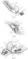
- FIG. 1A One embodiment of the system (10) that can move loads along stairs or other elevated surface is shown in Figure 1A , where its principle of operation is also shown.
- a flat and straight support surface (11) is deployed on stairs or other elevated surface (19) to provide structural support to a load transporting vehicle (12) so that said vehicle can climb along the stairs or the elevated surface (19) as shown in Figure 1B , Figure 2B and Figure 2C .
- the load transporting vehicle has a load support platform (13), means for propulsion (14), and means for maintaining the load support platform at a safe position for the load (15)(41)(42) as shown in Figure 4B .
- the load transporting vehicle makes contact with said support surface to transfer part of the load onto the support surface.
- the load transporting vehicle comprises means for keeping the platform horizontal and traction means for ascending/descending along the support surface placed on stairs or an elevated surface.
- an elevated surface (19) may be an elevated deck or patio as shown in Figure 2B or an elevated uneven terrain as shown in Figure 2C .
- the load (16) is a wheelchair (56) as shown in Figure 5A .
- the load transporting vehicle (12) climbs along the stairs by moving on the support structure while maintaining the load support platform (13) at an essentially horizontal position.
- the load support platform (13) remains at an essentially horizontal position during the entire operation as shown in Figure 2A .
- the load support platform is maintained at an essentially horizontal position by an arm (15) that is supported on a slider crank mechanism (42) on its upper side, and two beams interconnected at a junction point (45), the one being an actuation beam (43) and the other a passive beam (44).
- the movement of the arm in the vertical plane is driven by a balancing actuator (31) as shown in Figure 3A , which may be an electric drive motor (41) attached to the actuation beam (43) as shown in Figure 4B .
- the balancing actuator (31) is used for changing the length of the actuation beam (43), thus altering the angular position of interconnected arm (15) and beams.
- Said actuation beam (43) is non-back-drivable, i.e. achieving safe block in case of loss of power and/or failures.
- the balancing actuator uses a ball-screw actuated mechanism and is equipped with an additional mechanical brake.
- Said actuator that controls the vertical rotation of the arm is adjusted by means of a control system (33) taking feedback from inclination sensors (33) on the load transporting vehicle (12), in order to set the angular position of said arm which in turn sets the inclination of said platform in the essentially horizontal orientation.
- the arm (15) of this embodiment extends from the side of the vehicle positioned at the highest elevation of the stairs where it is supported on a slider crank mechanism (42), towards the side of the vehicle at the lowest elevation of the stairs where it is attached to means of propulsion (14) as shown in Figure 4B .
- Said means of propulsion provide traction to move the vehicle in the forward or backward direction over a flat and straight support surface (11) deployed on stairs, as shown in Figure 1 B.
- the means for propulsion of the load transporting vehicle (12) are two propulsion units (14), each mounted on a movable supporting arm (15) as shown in Figure 4B and Figure 6A , where each unit has a continuous track (32) as shown in Figure 3B .
- a traction actuator (34) controls the rotation of said continuous track (32). Traction force is achieved by mating surfaces, using a series of teeth on the continuous track (32) and a matching pattern on a non-slip top surface (17) of the support surface (11) in Figure 2A .
- the propulsion unit has non-slip wheels (claim 11)
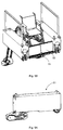
- Each propulsion unit (14) and supporting arm (15) are housed in a protective enclosure (51) to form part of the load bearing structure of the vehicle as shown in Figure 5A .
- a middle load support platform (30) shown in Figure 3B connects the two said enclosures and a load (16) can be positioned onto said platform for transportation along the stairs.
- Said middle load support platform (30) has a floor surface (52) and flaps (53) at both ends of said floor surface so that accidental sliding of the load off the platform can be prevented as shown in Figure 5A .
- Said flaps (53) move between the vertical position ( Figure 5B ), that prevents movement of the load off the platform, and a position where the flaps edge make contact with the ground ( Figure 5A ), that allows movement of the load on and off the platform. Flap movement is effected by a central bar (54) operated by a flap actuator (55) positioned in a channel so as to prevent any obstruction to the positioning or movement of the load on the load support platform, as seen in Figure 5A and Figure 5B
- Said floor surface (52) is manufactured using lightweight multi-layered double-wall structured composite material with cross-orientation.
- Said composite material is a sandwich panel, with thin glass/epoxy or carbon/epoxy skins, manufactured either as resin infusion, using shaped foam inserts, or direct fabrication using aluminium core sandwich panel 'cut-and-fold'
- a support surface (11) has a non-slip top surface (17) to prevent slip between the top surface and the vehicle and a non-slip bottom surface (18) to prevent slip between the bottom surface and the stairs, as shown in Figure 2A .
- Said non-slip top surface (17) has high friction material to prevent sliding of the propulsion means of the vehicle relative to the support surface, and/or geometrical patterns that act as obstacles to the sliding of the propulsion means of the vehicle relative to the support surface.
- Said non-slip bottom surface (18) has high friction material to prevent the sliding of the edge of each step of the stairs relative to the support surface, or geometrical patterns that act as obstacles to the sliding of the edge of each step of the stairs relative to the support surface.
- the load (16) is a wheelchair (56) or a similar device and/or a person.
- the system (10) can communicate with the person or with the wheelchair (56) via any mode of communication so that the system can get ready to receive the load as the load approaches the system, as shown in Figure 1A .
- the load transporting vehicle moves to the correct side of the stairs, namely upper or lower side of the stairs, where the load is anticipated to arrive and opens the flaps as shown in Figure 1A .
- the mode of communication between the load transporting vehicle and the wheelchair is via wireless communication between a sensor installed on the vehicle to uniquely identify a wheelchair user and a dedicated communication device on the wheelchair.
- the method of recognition is a visual recognition using a camera and associated image recognition software, or reception of signal from a smartphone activated by a dedicated application.
- a control system (33) continuously monitors the user input (up/down buttons) and the sensors (e.g. inclination sensors), in order to issues appropriate commands to the actuators (traction actuator (34), balancing actuator (31), flap actuator (55)).
- the sensors e.g. inclination sensors
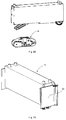
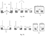
- the load transporting vehicle (12) is easily assembled and disassembled as shown in Figure 7B and Figure 7C .
- said vehicle is packed in two portable containers (70) in the disassembled condition as shown in Figure 7C , where one container houses one movable arm and its attached propulsion unit and another similar container houses the other movable arm and its attached propulsion unit.
- the middle load support platform (30) is arranged in two parts, each of said parts pivotably folding so that the load support platform (11) can be totally folded and securely held at the side of a container as shown in Figure 7C .
- containers can be easily and quickly carried and/or transported from the disassembly location to another location for assembly, therefore serving multiple locations with a single load transporting vehicle.
- said middle load support platform (30) is independently held as a single folded structure (71) in a collapsed condition, wherein the collapse of load support platform (11) into a folded single structure is achieved by a pulling action at the pivot line of the connecting segments, as shown in Figure 7B .
- said load transporting vehicle (12) that comprises of said middle load support platform (30) is packed in a single container (70) that can be easily and quickly carried and/or transported from the disassembly location to another location for assembly, therefore serving multiple locations with a single load transporting vehicle.
Priority Applications (2)
| Application Number | Priority Date | Filing Date | Title |
|---|---|---|---|
| ES16155813T ES2958397T3 (es) | 2016-02-16 | 2016-02-16 | Sistema para mover cargas a lo largo de una superficie inclinada |
| EP16155813.5A EP3208224B1 (fr) | 2016-02-16 | 2016-02-16 | Système de déplacement de charges le long d'une surface inclinée |
Applications Claiming Priority (1)
| Application Number | Priority Date | Filing Date | Title |
|---|---|---|---|
| EP16155813.5A EP3208224B1 (fr) | 2016-02-16 | 2016-02-16 | Système de déplacement de charges le long d'une surface inclinée |
Publications (3)
| Publication Number | Publication Date |
|---|---|
| EP3208224A1 true EP3208224A1 (fr) | 2017-08-23 |
| EP3208224C0 EP3208224C0 (fr) | 2023-08-23 |
| EP3208224B1 EP3208224B1 (fr) | 2023-08-23 |
Family
ID=55411215
Family Applications (1)
| Application Number | Title | Priority Date | Filing Date |
|---|---|---|---|
| EP16155813.5A Active EP3208224B1 (fr) | 2016-02-16 | 2016-02-16 | Système de déplacement de charges le long d'une surface inclinée |
Country Status (2)
| Country | Link |
|---|---|
| EP (1) | EP3208224B1 (fr) |
| ES (1) | ES2958397T3 (fr) |
Cited By (2)
| Publication number | Priority date | Publication date | Assignee | Title |
|---|---|---|---|---|
| CN110329877A (zh) * | 2019-05-15 | 2019-10-15 | 宁波立项电子有限公司 | 一种公共场所辅助轮椅在斜坡上下的扶梯 |
| CN115214819A (zh) * | 2022-08-19 | 2022-10-21 | 浙江工业大学 | 一种高稳定性的全自动爬楼装置 |
Citations (7)
| Publication number | Priority date | Publication date | Assignee | Title |
|---|---|---|---|---|
| US4411330A (en) | 1980-08-21 | 1983-10-25 | J. De Reus B.V. | Stair-climbing apparatus for a wheel chair or similar mobile transport means |
| US4674584A (en) | 1985-10-01 | 1987-06-23 | Gordon W. Rosenberg | Stair-climbing wheelchair with stair step sensing means |
| WO1997019887A1 (fr) | 1995-11-30 | 1997-06-05 | Roeed Svein Erik | Dispositif de levage |
| US6158536A (en) | 1996-10-29 | 2000-12-12 | Sunwa Ltd. | Stair-climbing vehicle for wheelchair |
| US6430769B1 (en) | 2000-10-27 | 2002-08-13 | Richard D. Allen | Wheelchair ramp with keyway joint |
| US7010825B1 (en) | 2003-08-08 | 2006-03-14 | Goldfinch Enterprises, Inc. | Telescoping ramp |
| US20150375965A1 (en) * | 2014-05-26 | 2015-12-31 | Drexel University | Modular Escalating Wheelchair Lift |
-
2016
- 2016-02-16 EP EP16155813.5A patent/EP3208224B1/fr active Active
- 2016-02-16 ES ES16155813T patent/ES2958397T3/es active Active
Patent Citations (7)
| Publication number | Priority date | Publication date | Assignee | Title |
|---|---|---|---|---|
| US4411330A (en) | 1980-08-21 | 1983-10-25 | J. De Reus B.V. | Stair-climbing apparatus for a wheel chair or similar mobile transport means |
| US4674584A (en) | 1985-10-01 | 1987-06-23 | Gordon W. Rosenberg | Stair-climbing wheelchair with stair step sensing means |
| WO1997019887A1 (fr) | 1995-11-30 | 1997-06-05 | Roeed Svein Erik | Dispositif de levage |
| US6158536A (en) | 1996-10-29 | 2000-12-12 | Sunwa Ltd. | Stair-climbing vehicle for wheelchair |
| US6430769B1 (en) | 2000-10-27 | 2002-08-13 | Richard D. Allen | Wheelchair ramp with keyway joint |
| US7010825B1 (en) | 2003-08-08 | 2006-03-14 | Goldfinch Enterprises, Inc. | Telescoping ramp |
| US20150375965A1 (en) * | 2014-05-26 | 2015-12-31 | Drexel University | Modular Escalating Wheelchair Lift |
Cited By (3)
| Publication number | Priority date | Publication date | Assignee | Title |
|---|---|---|---|---|
| CN110329877A (zh) * | 2019-05-15 | 2019-10-15 | 宁波立项电子有限公司 | 一种公共场所辅助轮椅在斜坡上下的扶梯 |
| CN115214819A (zh) * | 2022-08-19 | 2022-10-21 | 浙江工业大学 | 一种高稳定性的全自动爬楼装置 |
| CN115214819B (zh) * | 2022-08-19 | 2024-01-30 | 浙江工业大学 | 一种高稳定性的全自动爬楼装置 |
Also Published As
| Publication number | Publication date |
|---|---|
| EP3208224C0 (fr) | 2023-08-23 |
| EP3208224B1 (fr) | 2023-08-23 |
| ES2958397T3 (es) | 2024-02-08 |
Similar Documents
| Publication | Publication Date | Title |
|---|---|---|
| US11951052B2 (en) | Patient transfer apparatus with integrated tracks | |
| US7246671B2 (en) | Stair-climbing human transporter | |
| US7103935B2 (en) | Marine gangway to enable handicapped users to move between floating and fixed landings and related methods | |
| US20180029707A1 (en) | Cargo handling system, method and apparatus | |
| US10479385B2 (en) | Motorized handling truck | |
| US4747457A (en) | Platform truck for transporting bulky loads | |
| WO2013039425A1 (fr) | Véhicule de transport pour transporter des personnes et des marchandises dans les escaliers et sur des surfaces planes | |
| EP2547587B1 (fr) | Unité d'accès | |
| EP3528761B1 (fr) | Ensemble de rampe de véhicules | |
| EP3208224B1 (fr) | Système de déplacement de charges le long d'une surface inclinée | |
| US6802391B2 (en) | Aircraft non-ambulatory/ambulatory boarding and off-loading system | |
| EP2802524B1 (fr) | Appareil pour la montée et la descente d'escaliers avec un fauteuil roulant | |
| US11174677B2 (en) | Vehicle-mounted elevated access system | |
| WO2004039612A2 (fr) | Vehicule tous-terrains intelligent | |
| US9238512B1 (en) | Portable passenger boarding ramp assembly | |
| WO1997019887A1 (fr) | Dispositif de levage | |
| US8087496B1 (en) | Ramp system | |
| JPH10258781A (ja) | 階段昇降搬送車 | |
| EP3838712A1 (fr) | Chariot pour le transport d'une charge | |
| US11834838B2 (en) | Wheelchair ramp | |
| EP1988050A1 (fr) | Ascenseur d'escalier motorisé | |
| JP2021037865A (ja) | 台車、階段昇降装置及び搬送方法 | |
| JP2001180499A (ja) | ハンドカート | |
| ITUD20100205A1 (it) | Dispositivo per disabili | |
| CN218529090U (zh) | 接运装置的转弯收折轮 |
Legal Events
| Date | Code | Title | Description |
|---|---|---|---|
| PUAI | Public reference made under article 153(3) epc to a published international application that has entered the european phase |
Free format text: ORIGINAL CODE: 0009012 |
|
| STAA | Information on the status of an ep patent application or granted ep patent |
Free format text: STATUS: THE APPLICATION HAS BEEN PUBLISHED |
|
| AK | Designated contracting states |
Kind code of ref document: A1 Designated state(s): AL AT BE BG CH CY CZ DE DK EE ES FI FR GB GR HR HU IE IS IT LI LT LU LV MC MK MT NL NO PL PT RO RS SE SI SK SM TR |
|
| AX | Request for extension of the european patent |
Extension state: BA ME |
|
| STAA | Information on the status of an ep patent application or granted ep patent |
Free format text: STATUS: REQUEST FOR EXAMINATION WAS MADE |
|
| 17P | Request for examination filed |
Effective date: 20180309 |
|
| RBV | Designated contracting states (corrected) |
Designated state(s): AL AT BE BG CH CY CZ DE DK EE ES FI FR GB GR HR HU IE IS IT LI LT LU LV MC MK MT NL NO PL PT RO RS SE SI SK SM TR |
|
| STAA | Information on the status of an ep patent application or granted ep patent |
Free format text: STATUS: EXAMINATION IS IN PROGRESS |
|
| 17Q | First examination report despatched |
Effective date: 20190619 |
|
| 17Q | First examination report despatched |
Effective date: 20190730 |
|
| 17Q | First examination report despatched |
Effective date: 20190806 |
|
| STAA | Information on the status of an ep patent application or granted ep patent |
Free format text: STATUS: EXAMINATION IS IN PROGRESS |
|
| STAA | Information on the status of an ep patent application or granted ep patent |
Free format text: STATUS: EXAMINATION IS IN PROGRESS |
|
| GRAP | Despatch of communication of intention to grant a patent |
Free format text: ORIGINAL CODE: EPIDOSNIGR1 |
|
| STAA | Information on the status of an ep patent application or granted ep patent |
Free format text: STATUS: GRANT OF PATENT IS INTENDED |
|
| INTG | Intention to grant announced |
Effective date: 20220914 |
|
| GRAS | Grant fee paid |
Free format text: ORIGINAL CODE: EPIDOSNIGR3 |
|
| RAP1 | Party data changed (applicant data changed or rights of an application transferred) |
Owner name: GIVOTECH LTD |
|
| GRAA | (expected) grant |
Free format text: ORIGINAL CODE: 0009210 |
|
| STAA | Information on the status of an ep patent application or granted ep patent |
Free format text: STATUS: THE PATENT HAS BEEN GRANTED |
|
| AK | Designated contracting states |
Kind code of ref document: B1 Designated state(s): AL AT BE BG CH CY CZ DE DK EE ES FI FR GB GR HR HU IE IS IT LI LT LU LV MC MK MT NL NO PL PT RO RS SE SI SK SM TR |
|
| REG | Reference to a national code |
Ref country code: GB Ref legal event code: FG4D |
|
| REG | Reference to a national code |
Ref country code: CH Ref legal event code: EP |
|
| REG | Reference to a national code |
Ref country code: IE Ref legal event code: FG4D |
|
| REG | Reference to a national code |
Ref country code: DE Ref legal event code: R096 Ref document number: 602016082083 Country of ref document: DE |
|
| U01 | Request for unitary effect filed |
Effective date: 20230915 |
|
| U07 | Unitary effect registered |
Designated state(s): AT BE BG DE DK EE FI FR IT LT LU LV MT NL PT SE SI Effective date: 20230925 |
|
| PG25 | Lapsed in a contracting state [announced via postgrant information from national office to epo] |
Ref country code: GR Free format text: LAPSE BECAUSE OF FAILURE TO SUBMIT A TRANSLATION OF THE DESCRIPTION OR TO PAY THE FEE WITHIN THE PRESCRIBED TIME-LIMIT Effective date: 20231124 |
|
| PG25 | Lapsed in a contracting state [announced via postgrant information from national office to epo] |
Ref country code: IS Free format text: LAPSE BECAUSE OF FAILURE TO SUBMIT A TRANSLATION OF THE DESCRIPTION OR TO PAY THE FEE WITHIN THE PRESCRIBED TIME-LIMIT Effective date: 20231223 |
|
| PG25 | Lapsed in a contracting state [announced via postgrant information from national office to epo] |
Ref country code: RS Free format text: LAPSE BECAUSE OF FAILURE TO SUBMIT A TRANSLATION OF THE DESCRIPTION OR TO PAY THE FEE WITHIN THE PRESCRIBED TIME-LIMIT Effective date: 20230823 Ref country code: NO Free format text: LAPSE BECAUSE OF FAILURE TO SUBMIT A TRANSLATION OF THE DESCRIPTION OR TO PAY THE FEE WITHIN THE PRESCRIBED TIME-LIMIT Effective date: 20231123 Ref country code: IS Free format text: LAPSE BECAUSE OF FAILURE TO SUBMIT A TRANSLATION OF THE DESCRIPTION OR TO PAY THE FEE WITHIN THE PRESCRIBED TIME-LIMIT Effective date: 20231223 Ref country code: HR Free format text: LAPSE BECAUSE OF FAILURE TO SUBMIT A TRANSLATION OF THE DESCRIPTION OR TO PAY THE FEE WITHIN THE PRESCRIBED TIME-LIMIT Effective date: 20230823 Ref country code: GR Free format text: LAPSE BECAUSE OF FAILURE TO SUBMIT A TRANSLATION OF THE DESCRIPTION OR TO PAY THE FEE WITHIN THE PRESCRIBED TIME-LIMIT Effective date: 20231124 |
|
| REG | Reference to a national code |
Ref country code: ES Ref legal event code: FG2A Ref document number: 2958397 Country of ref document: ES Kind code of ref document: T3 Effective date: 20240208 |
|
| PG25 | Lapsed in a contracting state [announced via postgrant information from national office to epo] |
Ref country code: PL Free format text: LAPSE BECAUSE OF FAILURE TO SUBMIT A TRANSLATION OF THE DESCRIPTION OR TO PAY THE FEE WITHIN THE PRESCRIBED TIME-LIMIT Effective date: 20230823 |