EP3207979A1 - Feinblasige diffusoranordnung - Google Patents
Feinblasige diffusoranordnung Download PDFInfo
- Publication number
- EP3207979A1 EP3207979A1 EP16158077.4A EP16158077A EP3207979A1 EP 3207979 A1 EP3207979 A1 EP 3207979A1 EP 16158077 A EP16158077 A EP 16158077A EP 3207979 A1 EP3207979 A1 EP 3207979A1
- Authority
- EP
- European Patent Office
- Prior art keywords
- diffuser
- circumferential bead
- flexible
- membrane
- edge ring
- Prior art date
- Legal status (The legal status is an assumption and is not a legal conclusion. Google has not performed a legal analysis and makes no representation as to the accuracy of the status listed.)
- Granted
Links
- 239000012528 membrane Substances 0.000 claims abstract description 73
- 239000011324 bead Substances 0.000 claims abstract description 51
- 238000009826 distribution Methods 0.000 claims description 24
- 239000004033 plastic Substances 0.000 claims description 19
- 229920003023 plastic Polymers 0.000 claims description 19
- 238000001746 injection moulding Methods 0.000 claims description 13
- 238000004065 wastewater treatment Methods 0.000 claims description 12
- 230000013011 mating Effects 0.000 claims description 9
- 238000000034 method Methods 0.000 claims description 7
- 229920001971 elastomer Polymers 0.000 claims description 4
- 239000000463 material Substances 0.000 claims description 4
- 238000004891 communication Methods 0.000 claims description 3
- 239000000806 elastomer Substances 0.000 claims description 3
- 238000004519 manufacturing process Methods 0.000 claims description 3
- 239000012815 thermoplastic material Substances 0.000 claims description 2
- 238000005516 engineering process Methods 0.000 abstract description 3
- 238000009434 installation Methods 0.000 abstract description 2
- 239000007789 gas Substances 0.000 description 36
- 230000000712 assembly Effects 0.000 description 15
- 238000000429 assembly Methods 0.000 description 15
- 239000002351 wastewater Substances 0.000 description 9
- -1 but not limited to Polymers 0.000 description 6
- 238000000465 moulding Methods 0.000 description 6
- 238000002347 injection Methods 0.000 description 5
- 239000007924 injection Substances 0.000 description 5
- 230000015572 biosynthetic process Effects 0.000 description 3
- 229920001343 polytetrafluoroethylene Polymers 0.000 description 3
- 239000004810 polytetrafluoroethylene Substances 0.000 description 3
- 229920002943 EPDM rubber Polymers 0.000 description 2
- YCKRFDGAMUMZLT-UHFFFAOYSA-N Fluorine atom Chemical compound [F] YCKRFDGAMUMZLT-UHFFFAOYSA-N 0.000 description 2
- QVGXLLKOCUKJST-UHFFFAOYSA-N atomic oxygen Chemical compound [O] QVGXLLKOCUKJST-UHFFFAOYSA-N 0.000 description 2
- 230000031018 biological processes and functions Effects 0.000 description 2
- 238000005520 cutting process Methods 0.000 description 2
- 229910052731 fluorine Inorganic materials 0.000 description 2
- 239000011737 fluorine Substances 0.000 description 2
- 238000002844 melting Methods 0.000 description 2
- 230000008018 melting Effects 0.000 description 2
- 239000001301 oxygen Substances 0.000 description 2
- 229910052760 oxygen Inorganic materials 0.000 description 2
- 230000008569 process Effects 0.000 description 2
- 230000004044 response Effects 0.000 description 2
- 229930040373 Paraformaldehyde Natural products 0.000 description 1
- 239000004743 Polypropylene Substances 0.000 description 1
- XECAHXYUAAWDEL-UHFFFAOYSA-N acrylonitrile butadiene styrene Chemical compound C=CC=C.C=CC#N.C=CC1=CC=CC=C1 XECAHXYUAAWDEL-UHFFFAOYSA-N 0.000 description 1
- 239000004676 acrylonitrile butadiene styrene Substances 0.000 description 1
- 229920000122 acrylonitrile butadiene styrene Polymers 0.000 description 1
- 238000013459 approach Methods 0.000 description 1
- 230000008859 change Effects 0.000 description 1
- 238000000576 coating method Methods 0.000 description 1
- 230000008878 coupling Effects 0.000 description 1
- 238000010168 coupling process Methods 0.000 description 1
- 238000005859 coupling reaction Methods 0.000 description 1
- 230000007812 deficiency Effects 0.000 description 1
- 238000013461 design Methods 0.000 description 1
- 229920001973 fluoroelastomer Polymers 0.000 description 1
- 230000005484 gravity Effects 0.000 description 1
- 238000005470 impregnation Methods 0.000 description 1
- 239000007788 liquid Substances 0.000 description 1
- 238000012986 modification Methods 0.000 description 1
- 230000004048 modification Effects 0.000 description 1
- 210000003739 neck Anatomy 0.000 description 1
- 229920006324 polyoxymethylene Polymers 0.000 description 1
- 229920001155 polypropylene Polymers 0.000 description 1
- 229920000915 polyvinyl chloride Polymers 0.000 description 1
- 239000004800 polyvinyl chloride Substances 0.000 description 1
- 229920005989 resin Polymers 0.000 description 1
- 239000011347 resin Substances 0.000 description 1
- 239000007787 solid Substances 0.000 description 1
- 239000002910 solid waste Substances 0.000 description 1
- 239000000725 suspension Substances 0.000 description 1
- 229920001169 thermoplastic Polymers 0.000 description 1
- 239000004416 thermosoftening plastic Substances 0.000 description 1
- 238000012546 transfer Methods 0.000 description 1
Images

Classifications
-
- C—CHEMISTRY; METALLURGY
- C02—TREATMENT OF WATER, WASTE WATER, SEWAGE, OR SLUDGE
- C02F—TREATMENT OF WATER, WASTE WATER, SEWAGE, OR SLUDGE
- C02F3/00—Biological treatment of water, waste water, or sewage
- C02F3/02—Aerobic processes
-
- C—CHEMISTRY; METALLURGY
- C02—TREATMENT OF WATER, WASTE WATER, SEWAGE, OR SLUDGE
- C02F—TREATMENT OF WATER, WASTE WATER, SEWAGE, OR SLUDGE
- C02F3/00—Biological treatment of water, waste water, or sewage
- C02F3/02—Aerobic processes
- C02F3/12—Activated sludge processes
- C02F3/20—Activated sludge processes using diffusers
- C02F3/201—Perforated, resilient plastic diffusers, e.g. membranes, sheets, foils, tubes, hoses
-
- B—PERFORMING OPERATIONS; TRANSPORTING
- B01—PHYSICAL OR CHEMICAL PROCESSES OR APPARATUS IN GENERAL
- B01F—MIXING, e.g. DISSOLVING, EMULSIFYING OR DISPERSING
- B01F23/00—Mixing according to the phases to be mixed, e.g. dispersing or emulsifying
- B01F23/20—Mixing gases with liquids
- B01F23/23—Mixing gases with liquids by introducing gases into liquid media, e.g. for producing aerated liquids
- B01F23/231—Mixing gases with liquids by introducing gases into liquid media, e.g. for producing aerated liquids by bubbling
- B01F23/23105—Arrangement or manipulation of the gas bubbling devices
- B01F23/2312—Diffusers
- B01F23/23124—Diffusers consisting of flexible porous or perforated material, e.g. fabric
- B01F23/231241—Diffusers consisting of flexible porous or perforated material, e.g. fabric the outlets being in the form of perforations
-
- B—PERFORMING OPERATIONS; TRANSPORTING
- B01—PHYSICAL OR CHEMICAL PROCESSES OR APPARATUS IN GENERAL
- B01F—MIXING, e.g. DISSOLVING, EMULSIFYING OR DISPERSING
- B01F23/00—Mixing according to the phases to be mixed, e.g. dispersing or emulsifying
- B01F23/20—Mixing gases with liquids
- B01F23/23—Mixing gases with liquids by introducing gases into liquid media, e.g. for producing aerated liquids
- B01F23/231—Mixing gases with liquids by introducing gases into liquid media, e.g. for producing aerated liquids by bubbling
- B01F23/23105—Arrangement or manipulation of the gas bubbling devices
- B01F23/2312—Diffusers
- B01F23/23125—Diffusers characterised by the way in which they are assembled or mounted; Fabricating the parts of the diffusers
-
- B—PERFORMING OPERATIONS; TRANSPORTING
- B01—PHYSICAL OR CHEMICAL PROCESSES OR APPARATUS IN GENERAL
- B01F—MIXING, e.g. DISSOLVING, EMULSIFYING OR DISPERSING
- B01F23/00—Mixing according to the phases to be mixed, e.g. dispersing or emulsifying
- B01F23/20—Mixing gases with liquids
- B01F23/23—Mixing gases with liquids by introducing gases into liquid media, e.g. for producing aerated liquids
- B01F23/231—Mixing gases with liquids by introducing gases into liquid media, e.g. for producing aerated liquids by bubbling
- B01F23/23105—Arrangement or manipulation of the gas bubbling devices
- B01F23/2312—Diffusers
- B01F23/23126—Diffusers characterised by the shape of the diffuser element
- B01F23/231262—Diffusers characterised by the shape of the diffuser element having disc shape
-
- B—PERFORMING OPERATIONS; TRANSPORTING
- B29—WORKING OF PLASTICS; WORKING OF SUBSTANCES IN A PLASTIC STATE IN GENERAL
- B29C—SHAPING OR JOINING OF PLASTICS; SHAPING OF MATERIAL IN A PLASTIC STATE, NOT OTHERWISE PROVIDED FOR; AFTER-TREATMENT OF THE SHAPED PRODUCTS, e.g. REPAIRING
- B29C45/00—Injection moulding, i.e. forcing the required volume of moulding material through a nozzle into a closed mould; Apparatus therefor
- B29C45/14—Injection moulding, i.e. forcing the required volume of moulding material through a nozzle into a closed mould; Apparatus therefor incorporating preformed parts or layers, e.g. injection moulding around inserts or for coating articles
- B29C45/14065—Positioning or centering articles in the mould
-
- B—PERFORMING OPERATIONS; TRANSPORTING
- B29—WORKING OF PLASTICS; WORKING OF SUBSTANCES IN A PLASTIC STATE IN GENERAL
- B29C—SHAPING OR JOINING OF PLASTICS; SHAPING OF MATERIAL IN A PLASTIC STATE, NOT OTHERWISE PROVIDED FOR; AFTER-TREATMENT OF THE SHAPED PRODUCTS, e.g. REPAIRING
- B29C45/00—Injection moulding, i.e. forcing the required volume of moulding material through a nozzle into a closed mould; Apparatus therefor
- B29C45/14—Injection moulding, i.e. forcing the required volume of moulding material through a nozzle into a closed mould; Apparatus therefor incorporating preformed parts or layers, e.g. injection moulding around inserts or for coating articles
- B29C45/14336—Coating a portion of the article, e.g. the edge of the article
- B29C45/14377—Coating a portion of the article, e.g. the edge of the article using an additional insert, e.g. a fastening element
-
- B—PERFORMING OPERATIONS; TRANSPORTING
- B29—WORKING OF PLASTICS; WORKING OF SUBSTANCES IN A PLASTIC STATE IN GENERAL
- B29C—SHAPING OR JOINING OF PLASTICS; SHAPING OF MATERIAL IN A PLASTIC STATE, NOT OTHERWISE PROVIDED FOR; AFTER-TREATMENT OF THE SHAPED PRODUCTS, e.g. REPAIRING
- B29C45/00—Injection moulding, i.e. forcing the required volume of moulding material through a nozzle into a closed mould; Apparatus therefor
- B29C45/17—Component parts, details or accessories; Auxiliary operations
- B29C45/26—Moulds
- B29C45/2628—Moulds with mould parts forming holes in or through the moulded article, e.g. for bearing cages
-
- C—CHEMISTRY; METALLURGY
- C02—TREATMENT OF WATER, WASTE WATER, SEWAGE, OR SLUDGE
- C02F—TREATMENT OF WATER, WASTE WATER, SEWAGE, OR SLUDGE
- C02F3/00—Biological treatment of water, waste water, or sewage
- C02F3/02—Aerobic processes
- C02F3/12—Activated sludge processes
- C02F3/20—Activated sludge processes using diffusers
- C02F3/208—Membrane aeration
-
- C—CHEMISTRY; METALLURGY
- C02—TREATMENT OF WATER, WASTE WATER, SEWAGE, OR SLUDGE
- C02F—TREATMENT OF WATER, WASTE WATER, SEWAGE, OR SLUDGE
- C02F7/00—Aeration of stretches of water
-
- B—PERFORMING OPERATIONS; TRANSPORTING
- B29—WORKING OF PLASTICS; WORKING OF SUBSTANCES IN A PLASTIC STATE IN GENERAL
- B29C—SHAPING OR JOINING OF PLASTICS; SHAPING OF MATERIAL IN A PLASTIC STATE, NOT OTHERWISE PROVIDED FOR; AFTER-TREATMENT OF THE SHAPED PRODUCTS, e.g. REPAIRING
- B29C45/00—Injection moulding, i.e. forcing the required volume of moulding material through a nozzle into a closed mould; Apparatus therefor
- B29C45/14—Injection moulding, i.e. forcing the required volume of moulding material through a nozzle into a closed mould; Apparatus therefor incorporating preformed parts or layers, e.g. injection moulding around inserts or for coating articles
- B29C45/14065—Positioning or centering articles in the mould
- B29C2045/14147—Positioning or centering articles in the mould using pins or needles penetrating through the insert
-
- B—PERFORMING OPERATIONS; TRANSPORTING
- B29—WORKING OF PLASTICS; WORKING OF SUBSTANCES IN A PLASTIC STATE IN GENERAL
- B29C—SHAPING OR JOINING OF PLASTICS; SHAPING OF MATERIAL IN A PLASTIC STATE, NOT OTHERWISE PROVIDED FOR; AFTER-TREATMENT OF THE SHAPED PRODUCTS, e.g. REPAIRING
- B29C45/00—Injection moulding, i.e. forcing the required volume of moulding material through a nozzle into a closed mould; Apparatus therefor
- B29C45/14—Injection moulding, i.e. forcing the required volume of moulding material through a nozzle into a closed mould; Apparatus therefor incorporating preformed parts or layers, e.g. injection moulding around inserts or for coating articles
- B29C45/14336—Coating a portion of the article, e.g. the edge of the article
- B29C2045/14442—Coating a portion of the article, e.g. the edge of the article injecting a grill or grid on the insert
-
- B—PERFORMING OPERATIONS; TRANSPORTING
- B29—WORKING OF PLASTICS; WORKING OF SUBSTANCES IN A PLASTIC STATE IN GENERAL
- B29K—INDEXING SCHEME ASSOCIATED WITH SUBCLASSES B29B, B29C OR B29D, RELATING TO MOULDING MATERIALS OR TO MATERIALS FOR MOULDS, REINFORCEMENTS, FILLERS OR PREFORMED PARTS, e.g. INSERTS
- B29K2101/00—Use of unspecified macromolecular compounds as moulding material
- B29K2101/12—Thermoplastic materials
-
- B—PERFORMING OPERATIONS; TRANSPORTING
- B29—WORKING OF PLASTICS; WORKING OF SUBSTANCES IN A PLASTIC STATE IN GENERAL
- B29K—INDEXING SCHEME ASSOCIATED WITH SUBCLASSES B29B, B29C OR B29D, RELATING TO MOULDING MATERIALS OR TO MATERIALS FOR MOULDS, REINFORCEMENTS, FILLERS OR PREFORMED PARTS, e.g. INSERTS
- B29K2623/00—Use of polyalkenes or derivatives thereof for preformed parts, e.g. for inserts
- B29K2623/16—EPM, i.e. ethylene-propylene copolymers; EPDM, i.e. ethylene-propylene-diene copolymers; EPT, i.e. ethylene-propylene terpolymers
-
- B—PERFORMING OPERATIONS; TRANSPORTING
- B29—WORKING OF PLASTICS; WORKING OF SUBSTANCES IN A PLASTIC STATE IN GENERAL
- B29L—INDEXING SCHEME ASSOCIATED WITH SUBCLASS B29C, RELATING TO PARTICULAR ARTICLES
- B29L2001/00—Articles provided with screw threads
-
- B—PERFORMING OPERATIONS; TRANSPORTING
- B29—WORKING OF PLASTICS; WORKING OF SUBSTANCES IN A PLASTIC STATE IN GENERAL
- B29L—INDEXING SCHEME ASSOCIATED WITH SUBCLASS B29C, RELATING TO PARTICULAR ARTICLES
- B29L2009/00—Layered products
- B29L2009/001—Layered products the layers being loose
-
- B—PERFORMING OPERATIONS; TRANSPORTING
- B29—WORKING OF PLASTICS; WORKING OF SUBSTANCES IN A PLASTIC STATE IN GENERAL
- B29L—INDEXING SCHEME ASSOCIATED WITH SUBCLASS B29C, RELATING TO PARTICULAR ARTICLES
- B29L2031/00—Other particular articles
- B29L2031/737—Articles provided with holes, e.g. grids, sieves
-
- B—PERFORMING OPERATIONS; TRANSPORTING
- B29—WORKING OF PLASTICS; WORKING OF SUBSTANCES IN A PLASTIC STATE IN GENERAL
- B29L—INDEXING SCHEME ASSOCIATED WITH SUBCLASS B29C, RELATING TO PARTICULAR ARTICLES
- B29L2031/00—Other particular articles
- B29L2031/755—Membranes, diaphragms
-
- Y—GENERAL TAGGING OF NEW TECHNOLOGICAL DEVELOPMENTS; GENERAL TAGGING OF CROSS-SECTIONAL TECHNOLOGIES SPANNING OVER SEVERAL SECTIONS OF THE IPC; TECHNICAL SUBJECTS COVERED BY FORMER USPC CROSS-REFERENCE ART COLLECTIONS [XRACs] AND DIGESTS
- Y02—TECHNOLOGIES OR APPLICATIONS FOR MITIGATION OR ADAPTATION AGAINST CLIMATE CHANGE
- Y02W—CLIMATE CHANGE MITIGATION TECHNOLOGIES RELATED TO WASTEWATER TREATMENT OR WASTE MANAGEMENT
- Y02W10/00—Technologies for wastewater treatment
- Y02W10/10—Biological treatment of water, waste water, or sewage
Definitions
- the present invention relates generally to wastewater treatment, and, more particularly, to fine bubble diffuser assemblies for use in wastewater treatment.
- a flexible diffuser typically comprises a disc-, tube-, or strip-shaped membrane that is constructed of rubber or other similar materials, which is punctured to provide a number of perforations in the form of holes or slits. In operation, pressurized air is sent through these perforations to create a plume of small bubbles. The bubbles rise through the wastewater and provide the surrounding wastewater with the oxygen needed to sustain the desired biological processes occurring therein.
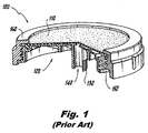
- FIG. 1 shows a partially-broken side perspective view of a fine bubble diffuser assembly 100 that is conventionally used in modem wastewater treatment facilities for "submerged" treatment of the wastewater.
- Wastewater treatment with such assemblies is described in, as just one example, F.L. Burton, Wastewater Engineering (McGraw-Hill College, 2002 ), which is hereby incorporated by reference herein.
- a plurality of diffuser assemblies is arrayed on several lateral distribution pipes that cross a wastewater treatment tank. Diffuser assemblies may, for example, be placed every foot along a given lateral distribution pipe.
- a blower located near the tank sends compressed air to the lateral distribution pipe via several support pipes (e.g., drop pipes and manifold pipes).
- a flexible diffuser membrane 110 sits atop a diffuser body 120.
- the diffuser body 120 comprises a threaded mating tube 130, an air inlet orifice 140, and a receiving surface 150 for coupling to a retainer ring 160.
- the retainer ring 160 holds the flexible diffuser membrane 110 against the diffuser body 120.
- the flexible diffuser membrane 110 collapses on the diffuser body 120 to close the perforations and prevent the liquid from entering the diffuser body 120 in the opposite direction.
- a flexible diffuser membrane 110 configured in this way produces bubbles smaller than five millimeters in diameter. The resultant large ratio of surface area to volume in these bubbles promotes efficient oxygen mass transfer between the bubbles and the surrounding wastewater. The fine bubbles also cause an upward movement in the wastewater treatment tank, which helps to keep solid waste in suspension and to mix the contents of the tank.
- the diffuser assembly In order to change a diffuser membrane on a conventional threaded diffuser assembly like the diffuser assembly 100, for example, the diffuser assembly must be placed on a fixture after being removed from its gas distribution pipe, and the diffuser assembly's retainer ring removed to allow its diffuser membrane to be lifted away. A new diffuser membrane must then be put in its place, and the retainer ring re-greased and re-applied to the correct torque value. In many cases, the retainer ring must also be replaced due to damage. Only then may the completed diffuser assembly be removed from the fixture and re-mounted to its gas distribution pipe, again to the correct torque value.
- Embodiments of the present invention address the above-identified needs by providing a diffuser assembly with a flexible diffuser membrane that is captured by the diffuser body utilizing an integral edge ring that cannot be separated from the remainder of the diffuser body.
- a diffuser assembly may provide a disposable diffuser assembly option with many advantages over conventional technologies, such as improved ease of installation, lower weight, and lower cost.
- aspects of the invention are directed to a diffuser assembly comprising a flexible diffuser membrane and a diffuser body.
- the flexible diffuser membrane defines a circumferential bead.
- the diffuser body defines a circular plate underlying the flexible diffuser membrane, and an edge ring covering a covered portion of the circumferential bead.
- the edge ring defines an inside surface that conforms to an outside shape of the covered portion of the circumferential bead.
- the edge ring is integral to the diffuser body.
- the flexible diffuser membrane may comprise an elastomer and a plurality of perforations therethrough.
- the diffuser body may comprise a thermoplastic material.
- the circular plate may define an opening
- the diffuser body may define a threaded mating tube with an inside gas passage that terminates in the opening.
- the flexible diffuser membrane may define an intact region overlying the opening with no perforations therethrough.
- the edge ring may define a plurality of slots therein, each slot of the plurality of slots exposing a respective outside surface portion of the circumferential bead.
- the covered portion may consist of a majority of the circumferential bead.
- the circumferential bead may not be substantially compressed by the diffuser body.
- a thin sheet may be disposed between the circular plate and the flexible diffuser membrane, and the thin sheet may comprise a plastic material.
- Additional aspects of the invention are directed to a wastewater treatment tank including a diffuser assembly.
- the diffuser assembly comprises a flexible diffuser membrane and a diffuser body.
- the flexible diffuser membrane defines a circumferential bead.
- the diffuser body defines a circular plate underlying the flexible diffuser membrane, and an edge ring covering a covered portion of the circumferential bead.
- the edge ring defines an inside surface that conforms to an outside shape of the covered portion of the circumferential bead.
- the edge ring is integral to the diffuser body.
- the wastewater treatment tank may further comprise a gas distribution pipe, wherein the diffuser assembly is in gaseous communication with an inside of the gas distribution pipe.
- a flexible diffuser membrane is received that defines a circumferential bead.
- a diffuser body is formed at least in part by injection molding defining a circular plate underlying the flexible diffuser membrane, and an edge ring covering a covered portion of the circumferential bead.
- the edge ring defines an inside surface that conforms to an outside shape of the covered portion of the circumferential bead.
- the edge ring is integral to the diffuser body.
- the circumferential bead may be supported by a plurality of supporting teeth during the injection molding.
- the edge ring may define a plurality of slots therein. Each slot of the plurality of slots may expose a respective outside surface portion of the circumferential bead and be positioned where a respective one of the plurality of supporting teeth was located during the injection molding.
- molten plastic may directly contact the covered portion of the circumferential bead.
- the method may further comprise the step of placing a thin sheet against the flexible diffuser membrane before the step of forming the diffuser body so that the thin sheet is disposed between the flexible diffuser membrane and the circular plate after the step of forming the diffuser body.
- the thin sheet may be formed of a plastic.
- the circular plate may define an opening
- the diffuser body may define a threaded mating tube with an inside gas passage that terminates in the opening.
- an element is "not substantially compressed” by something else if the element's volume is not modified by more than ten percent.
- the term “directly” means without any intervening elements.
- a feature defined by an element is “integral” to that element if the feature cannot be separated from the remainder of that element without cutting, breaking, melting, or otherwise damaging the element.
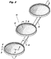
- FIG. 2 shows a perspective view of three diffuser assemblies 200 in accordance with an illustrative embodiment of the invention with the diffuser assemblies 200 attached to a gas distribution pipe 300.
- Each of the diffuser assemblies 200 comprises a respective diffuser body 205, which supports a respective flexible diffuser membrane 210.
- the diffuser assemblies 200 and the gas distribution pipe 300 may be placed at the bottom of a wastewater treatment tank.
- the gas distribution pipe 300 may then be caused to supply a gas (e.g., air) to the diffuser assemblies 200 so as to cause the diffuser assemblies 200 to release bubbles into the surrounding wastewater.
- a gas e.g., air
- FIGS. 2-6 Additional details of a representative one of the diffuser assemblies 200 are shown in FIGS. 2-6 .
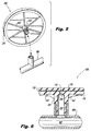
- FIGS. 3 and 4 show perspective sectional views of respective portions of the diffuser assembly 200 along the planes indicated in FIG. 2
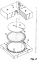
- FIG. 5 shows an exploded perspective view of the underside of the diffuser assembly 200 in relation to the gas distribution pipe 300.
- FIG. 6 shows a sectional view of portions of the diffuser assembly 200 and the gas distribution pipe 300 along the plane indicated in FIG. 2 .
- the flexible diffuser membrane 210 is disk-shaped and defines a circumferential bead 215.
- the circumferential bead 215 has a square cross-section with rounded corners.
- a plurality of perforations penetrate the flexible diffuser membrane 210 except in an intact region at the center of the flexible diffuser membrane 210 (further described and labeled below).
- the diffuser body 205 defines a circular plate 220 that underlies the flexible diffuser membrane 210, as well as an edge ring 225 covering a portion of the circumferential bead 215 of the flexible diffuser membrane 210 (hereinafter, the "covered portion" of the circumferential bead 215).
- the covered portion consists of a majority of the circumferential bead 215.
- the edge ring 225 acts to retain the flexible diffuser membrane 210 to the diffuser body 205.
- the edge ring 225 defines an inside surface 230 that conforms to an outside shape of the covered portion of the circumferential bead 215 without significantly compressing the circumferential bead 215.
- the edge ring 225 defines a plurality of slots 235 therein, each slot 235 exposing a respective outside surface portion 240 of the circumferential bead 215.
- the edge ring 225 is integral to the diffuser body 205, meaning that the edge ring 225 cannot be removed from the remainder of the diffuser body 205 without cutting, breaking, melting, or otherwise damaging the diffuser body 205. This clearly differs from the conventional diffuser assembly 100 in FIG. 1 , where the retainer ring 160 is distinct from the diffuser body 120 and is removably threaded onto the receiving surface 150 of the diffuser body 120.
- the diffuser body 205 further describes a threaded mating tube 245 with an inside gas passage 250 that terminates in an opening 255 in the circular plate 220.
- the inside gas passage 250 is in gaseous communication with an inside 305 of the gas distribution pipe 300.
- the inside gas passage 250 necks down as it approaches the opening 255 in the circular plate 220, forming an orifice 260.
- the size of this orifice 260 may be tailored to the specific application.
- Several ribs 265 on the bottom of the diffuser body 205 lend additional strength to the diffuser body 205.
- a thin circular sheet 270 is disposed between the flexible diffuser membrane 210 and the circular plate 220 of the diffuser body 205.
- the thin circular sheet 270 includes a center hole 275 that overlies the opening 255 in the circular plate 220.
- the integral nature of the edge ring 225 as well as the conformity of the inside surface 230 of the edge ring 225 with respect to the covered portion of the circumferential bead 215 may be obtained by injection molding the diffuser body 205 around the flexible diffuser membrane 210.
- the thin circular sheet 270 aids in this process.
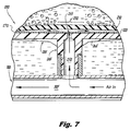
- FIG. 7 shows a sectional view of respective portions of the diffuser assembly 200 and the gas distribution pipe 300 along the plane indicated in FIG. 2 , but in a condition wherein pressurized gas (in this case, air) is being supplied to the diffuser assembly 200 via the gas distribution pipe 300.
- pressurized gas in this case, air
- the gas pressure expands the flexible diffuser membrane 210 away from the diffuser body 205 and causes the gas to discharge from the perforations of the flexible diffuser membrane 210 as fine bubbles.
- An intact region 280 of the flexible diffuser membrane 210 which is devoid of perforations, sits above the opening 255 in the circular plate 220. This intact region 280 allows the diffuser assembly to act as a check valve and prevent wastewater from flooding the gas distribution pipe 300 when the pressurized gas is turned off.
- the flexible diffuser membrane 210 collapses back onto the diffuser body 205 both in response to the natural tendency of the flexible diffuser membrane 210 to return to a relaxed, un-stretched shape and in response to the weight of the surrounding wastewater. So relaxed, the condition shown in FIG. 6 is recreated. With the flexible diffuser membrane 210 positioned as in FIG. 6 , the intact region 280 of the flexible diffuser membrane 210 overlies the opening 255 and prevents wastewater from entering the inside gas passage 250 in the opposite direction.
- the flexible diffuser membrane 210 may comprise an elastomer such as, but not limited to, ethylene propylene diene monomer (EPDM). One or both sides of the flexible diffuser membrane 210 may be covered in a fluoroelastomer such as, for example, polytetrafluoroethylene (PTFE), or the flexible diffuser membrane 210 may be impregnated with fluorine. Both PTFE coatings and fluorine impregnation have been demonstrated to reduce the rate at which diffuser membranes are fouled.
- the diffuser body 205 may comprise an injection-moldable thermoplastic such as, for example, polypropylene, acrylonitrile butadiene styrene, polyvinyl chloride, and polyoxymethylene.
- the thin circular sheet 270 may also comprise a plastic; in a preferred embodiment, the thin circular sheet 270 is formed of the same plastic as the diffuser body 205.
- the diffuser assembly 200 may be formed by injection molding the diffuser body 205 around the flexible diffuser membrane 210 utilizing several molding parts.
- General aspects of injection molding will already be familiar to one having ordinary skill in the relevant arts, and are also described in several readily accessible publications including, as just one example, D.V. Rosatto et al., Injection Molding Handbook (Springer Science & Business Media, 2012 ), which is hereby incorporated by reference herein.
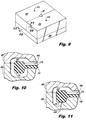
- a partially broken, exploded, perspective view of the molding parts in relation to elements of the diffuser assembly 200 is shown in FIG. 8
- FIG. 9 shows a perspective view of the molding parts closed about the same diffuser assembly elements in a condition prior to the injection of any molten plastic.
- the injection molding set forth in FIGS. 8 and 9 is performed with the flexible diffuser membrane 210 upside-down in relation to its orientation in FIGS. 2-7 .
- the molding parts include a bottom mold 400, a first top mold 405, a second top mold 410, and an insert piece 415.
- the flexible diffuser membrane 210 Prior to injecting any plastic, the flexible diffuser membrane 210 is placed top-down on the bottom mold 400 such that a plurality of supporting teeth 420 on the bottom mold 400 support the circumferential bead 215 of the flexible diffuser membrane 210.
- the thin circular sheet 270 is then placed on the flexible diffuser membrane 210.
- the first top mold 405, the second top mold 410, and the insert piece 415 are arranged on top of the bottom mold 400 to achieve the condition shown in FIG. 9 .
- the molds 400, 405, 410 define a first space 425 for molten plastic about the circumferential bead 215 of the flexible diffuser membrane 210, which allows formation of the edge ring 225 of the diffuser body 205.
- the molds 400, 405, 410 and the insert piece 415 define a second space 430 above the flexible diffuser membrane 210, which allows the formation of the circular plate 220 and the threaded mating tube 245.
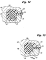
- FIGS. 10 and 11 show sectional views of the spaces 425, 430 proximate to the circumferential bead 215 along the planes indicated in FIG. 9 . From these views, it becomes clear how the supporting teeth 420 help to support the circumferential bead 215 in the space 425 intended for the formation of the edge ring 225.
- FIGS. 12 and 13 show sectional views of the same regions shown in FIGS. 10 and 11 , respectively, but after injection of the plastic forming the diffuser body 205.
- supporting teeth 420 are present ( FIG. 13 )
- no supporting teeth 420 are present ( FIG. 12 )
- the edge ring 225 defines the inside surface 230 that conforms to an outside shape of the covered portion of the circumferential bead 215.
- the just formed circular plate 220 had a tendency to fuse to the flexible diffuser membrane 210. Once so fused, the flexible diffuser membrane 210 did not perform as desired. In contrast, with the thin circular sheet 270 in place, no such fusing was observed and the diffuser assembly 200 performed properly.
- the thin circular sheet 270 is therefore a preferred aspect of the present design because of the manner in which it aids the manufacturing process.
- the above-described diffuser assembly 200 thereby becomes a one-piece, "solid-state" diffuser assembly, meaning that it does not use a separate diffuser membrane, body, and threaded retaining ring in the manner of the conventional diffuser assembly in FIG. 1 .
- the diffuser assembly 200 may provide several advantages over conventional technologies.
- the diffuser assembly 200 may be utilized in the field as a disposable part. When the flexible diffuser membrane 210 ultimately becomes fouled, the entire diffuser assembly 200 is replaced by a new one. Such a replacement is a simple operation, requiring only one new part, with no diffuser disassembly, greasing, special wrenches, or significant concerns about broken parts or leaks.
- the diffuser assembly 200 may weigh significantly less than a diffuser assembly made of separate components because it is not necessary to utilize thick plastic to deal with stress from tightly threaded retaining parts. Lastly, it may be possible to use less costly plastic resins when forming the diffuser assembly 200 because a single diffuser body is structurally more solid than a stressed threaded retaining ring and body. In some cases, recycled plastics may be an option.
Landscapes
- Engineering & Computer Science (AREA)
- Chemical & Material Sciences (AREA)
- Mechanical Engineering (AREA)
- Manufacturing & Machinery (AREA)
- Life Sciences & Earth Sciences (AREA)
- Chemical Kinetics & Catalysis (AREA)
- Hydrology & Water Resources (AREA)
- Water Supply & Treatment (AREA)
- Organic Chemistry (AREA)
- Environmental & Geological Engineering (AREA)
- Microbiology (AREA)
- Biodiversity & Conservation Biology (AREA)
- Separation Using Semi-Permeable Membranes (AREA)
- Aeration Devices For Treatment Of Activated Polluted Sludge (AREA)
Priority Applications (2)
| Application Number | Priority Date | Filing Date | Title |
|---|---|---|---|
| CN201610519039.3A CN107010715B (zh) | 2016-01-27 | 2016-07-04 | 扩散器组件及其制造方法以及包括该组件的废水处理槽 |
| CN201620694166.2U CN205933365U (zh) | 2016-01-27 | 2016-07-04 | 扩散器组件及包括该组件的废水处理槽 |
Applications Claiming Priority (1)
| Application Number | Priority Date | Filing Date | Title |
|---|---|---|---|
| US15/008,099 US10633267B2 (en) | 2016-01-27 | 2016-01-27 | Fine bubble diffuser assembly |
Publications (2)
| Publication Number | Publication Date |
|---|---|
| EP3207979A1 true EP3207979A1 (de) | 2017-08-23 |
| EP3207979B1 EP3207979B1 (de) | 2021-06-09 |
Family
ID=55699322
Family Applications (1)
| Application Number | Title | Priority Date | Filing Date |
|---|---|---|---|
| EP16158077.4A Active EP3207979B1 (de) | 2016-01-27 | 2016-03-01 | Feinblasige diffusoranordnung und herstellungsverfahren |
Country Status (3)
| Country | Link |
|---|---|
| US (1) | US10633267B2 (de) |
| EP (1) | EP3207979B1 (de) |
| CN (1) | CN107010715B (de) |
Families Citing this family (3)
| Publication number | Priority date | Publication date | Assignee | Title |
|---|---|---|---|---|
| DE102016113204B3 (de) * | 2016-07-18 | 2018-01-18 | Alexander Ott | Begasungseinrichtung |
| US10773982B2 (en) | 2017-08-10 | 2020-09-15 | Thomas E. Frankel | Diffuser assembly |
| WO2019060965A1 (en) * | 2017-09-29 | 2019-04-04 | Aquatec Maxcon Pty Ltd | DIFFUSER FOR AERATION OF A FLUID |
Citations (4)
| Publication number | Priority date | Publication date | Assignee | Title |
|---|---|---|---|---|
| EP0704237A2 (de) * | 1994-09-29 | 1996-04-03 | Karl-Heinz SCHÜSSLER | Begasungsvorrichtung |
| DE10119013A1 (de) * | 2001-04-18 | 2002-10-31 | Gummi Jaeger Kg Gmbh & Cie | Vorrichtung zum Belüften von Wasser |
| US20050046054A1 (en) * | 2003-07-25 | 2005-03-03 | Filtros, Ltd. | Diffuser assembly and method of making same |
| WO2006116067A1 (en) * | 2005-04-22 | 2006-11-02 | Hyclone Laboratories, Inc. | Gas spargers and related container systems |
Family Cites Families (24)
| Publication number | Priority date | Publication date | Assignee | Title |
|---|---|---|---|---|
| US1759983A (en) * | 1925-06-22 | 1930-05-27 | Henry B Houston | Screen for flotation processes |
| US4288394A (en) * | 1978-10-19 | 1981-09-08 | Water Pollution Control Corp. | Sewage aeration system |
| US4629126A (en) * | 1985-02-11 | 1986-12-16 | Autotrol Corporation | Fluid diffuser |
| US4569805A (en) * | 1984-09-28 | 1986-02-11 | The Gray Engineering Group Inc. | Apparatus for the submerged introduction of a fluid into a body of liquid |
| US4865778A (en) * | 1988-11-30 | 1989-09-12 | Aeration Engineering Resources | Composite diffuser assembly |
| US5422043A (en) * | 1990-08-31 | 1995-06-06 | Burris; William A. | Diffuser and diffusing method using dual surface tensions |
| US5330688A (en) * | 1993-05-27 | 1994-07-19 | Enviroquip International, Inc. | Flexible diffuser assembly for aeration applications |
| DE29518898U1 (de) * | 1995-12-01 | 1996-03-07 | Envicon Klärtechnik Verwaltungsgesellschaft mbH, 46537 Dinslaken | Belüftungseinrichtung |
| US5858283A (en) * | 1996-11-18 | 1999-01-12 | Burris; William Alan | Sparger |
| EP1089808B1 (de) * | 1998-03-02 | 2005-09-21 | USFilter Corporation | Doppelverteiler-zusammenstellung |
| US6367783B1 (en) * | 1998-06-23 | 2002-04-09 | Red Valve Company, Inc. | Fine bubble diffuser |
| US6464211B1 (en) * | 1999-08-31 | 2002-10-15 | United States Filter Corporation | Diffuser assembly |
| US6811148B2 (en) * | 2003-04-29 | 2004-11-02 | Stamford Scientific Int'l, Inc. | Quick-connect diffuser assembly |
| US6889964B2 (en) * | 2003-07-25 | 2005-05-10 | Filtros, Ltd. | Diffuser |
| US8657268B2 (en) * | 2007-02-28 | 2014-02-25 | Gregory P. Smiltneek | Methods and apparatus for wastewater treatment |
| TW200918160A (en) * | 2007-10-18 | 2009-05-01 | Kang Na Hsiung Entpr Co Ltd | Gas dispersion device for aeration system |
| US8061689B2 (en) * | 2007-12-31 | 2011-11-22 | Environmental Dynamics, Inc. | Disk diffuser with improved seal |
| US8002248B2 (en) * | 2008-06-19 | 2011-08-23 | Kang Na Hsiung Enterprise Co., Ltd. | Diffuser for an aeration system |
| DE102008047092A1 (de) * | 2008-09-12 | 2010-03-18 | Rehau Ag + Co. | Tellerbelüfter zur Abwasserreinigung |
| DE102010029754A1 (de) * | 2010-06-07 | 2011-12-08 | Invent Umwelt- Und Verfahrenstechnik Ag | Vorrichtung zum Begasen von Flüssigkeiten |
| KR101291238B1 (ko) | 2010-11-11 | 2013-08-01 | 주식회사 그린기술산업 | 역류방지 기능이 구비된 멤브레인 산기관 |
| US9567246B2 (en) * | 2012-11-19 | 2017-02-14 | Ant21 Co., Ltd | Air diffusion device |
| SE536982C2 (sv) * | 2013-03-18 | 2014-11-25 | Xylem Ip Man S R L | Luftarsammansättning för spridning av en gas i en vätska |
| CN205933365U (zh) * | 2016-01-27 | 2017-02-08 | 托马斯·E·弗兰克尔 | 扩散器组件及包括该组件的废水处理槽 |
-
2016
- 2016-01-27 US US15/008,099 patent/US10633267B2/en active Active
- 2016-03-01 EP EP16158077.4A patent/EP3207979B1/de active Active
- 2016-07-04 CN CN201610519039.3A patent/CN107010715B/zh active Active
Patent Citations (4)
| Publication number | Priority date | Publication date | Assignee | Title |
|---|---|---|---|---|
| EP0704237A2 (de) * | 1994-09-29 | 1996-04-03 | Karl-Heinz SCHÜSSLER | Begasungsvorrichtung |
| DE10119013A1 (de) * | 2001-04-18 | 2002-10-31 | Gummi Jaeger Kg Gmbh & Cie | Vorrichtung zum Belüften von Wasser |
| US20050046054A1 (en) * | 2003-07-25 | 2005-03-03 | Filtros, Ltd. | Diffuser assembly and method of making same |
| WO2006116067A1 (en) * | 2005-04-22 | 2006-11-02 | Hyclone Laboratories, Inc. | Gas spargers and related container systems |
Non-Patent Citations (2)
| Title |
|---|
| D.V. ROSATTO ET AL.: "Injection Molding Handbook", 2012, SPRINGER SCIENCE & BUSINESS MEDIA |
| F.L. BURTON: "Wastewater Engineering", 2002, MCGRAW-HILL |
Also Published As
| Publication number | Publication date |
|---|---|
| US20170210652A1 (en) | 2017-07-27 |
| CN107010715B (zh) | 2020-08-28 |
| CN107010715A (zh) | 2017-08-04 |
| EP3207979B1 (de) | 2021-06-09 |
| US10633267B2 (en) | 2020-04-28 |
Similar Documents
| Publication | Publication Date | Title |
|---|---|---|
| JP4846339B2 (ja) | 散気装置および散気システム | |
| US10633267B2 (en) | Fine bubble diffuser assembly | |
| US5330688A (en) | Flexible diffuser assembly for aeration applications | |
| KR100850340B1 (ko) | 여과 시스템 및 여과 시스템용 피팅 배치 | |
| WO1999067014A1 (en) | Fine bubble diffuser | |
| KR101246835B1 (ko) | 산기장치 | |
| KR101266507B1 (ko) | 산기장치 | |
| JP4704881B2 (ja) | 散気装置 | |
| JPH02144135A (ja) | 送風装置 | |
| KR101972151B1 (ko) | 견고한 결합과 유지가 가능한 멤브레인 산기관 | |
| US9539550B1 (en) | Coarse bubble diffuser for wastewater treatment | |
| KR101809814B1 (ko) | 일회용 멤브레인 산기관 | |
| JP2006075771A (ja) | 散気用弾性多孔体及び散気装置 | |
| EP3040113B1 (de) | Anordnung zur aufbereitung von abwasser | |
| KR101997611B1 (ko) | 디스크형 멤브레인 산기장치 | |
| JP3175355U (ja) | 散気装置 | |
| KR102482907B1 (ko) | 통기 요소 | |
| US20110132847A1 (en) | Methods and apparatus for wastewater treatment | |
| EP3450002B1 (de) | Diffusoranordnung und herstellungsverfahren dafür | |
| JP2007014899A (ja) | 散気装置 | |
| US20100275783A1 (en) | Liquid Separator and Tank System Comprising a Liquid Separator | |
| US7141203B2 (en) | Method of making a diffuser assembly | |
| CN205933365U (zh) | 扩散器组件及包括该组件的废水处理槽 | |
| KR102117681B1 (ko) | 에어 디퓨저 | |
| US6889964B2 (en) | Diffuser |
Legal Events
| Date | Code | Title | Description |
|---|---|---|---|
| PUAI | Public reference made under article 153(3) epc to a published international application that has entered the european phase |
Free format text: ORIGINAL CODE: 0009012 |
|
| STAA | Information on the status of an ep patent application or granted ep patent |
Free format text: STATUS: THE APPLICATION HAS BEEN PUBLISHED |
|
| AK | Designated contracting states |
Kind code of ref document: A1 Designated state(s): AL AT BE BG CH CY CZ DE DK EE ES FI FR GB GR HR HU IE IS IT LI LT LU LV MC MK MT NL NO PL PT RO RS SE SI SK SM TR |
|
| AX | Request for extension of the european patent |
Extension state: BA ME |
|
| STAA | Information on the status of an ep patent application or granted ep patent |
Free format text: STATUS: REQUEST FOR EXAMINATION WAS MADE |
|
| 17P | Request for examination filed |
Effective date: 20180213 |
|
| RBV | Designated contracting states (corrected) |
Designated state(s): AL AT BE BG CH CY CZ DE DK EE ES FI FR GB GR HR HU IE IS IT LI LT LU LV MC MK MT NL NO PL PT RO RS SE SI SK SM TR |
|
| STAA | Information on the status of an ep patent application or granted ep patent |
Free format text: STATUS: EXAMINATION IS IN PROGRESS |
|
| 17Q | First examination report despatched |
Effective date: 20190531 |
|
| GRAP | Despatch of communication of intention to grant a patent |
Free format text: ORIGINAL CODE: EPIDOSNIGR1 |
|
| STAA | Information on the status of an ep patent application or granted ep patent |
Free format text: STATUS: GRANT OF PATENT IS INTENDED |
|
| RIC1 | Information provided on ipc code assigned before grant |
Ipc: B29C 45/26 20060101ALI20200629BHEP Ipc: B29C 45/14 20060101ALI20200629BHEP Ipc: B29K 623/00 20060101ALN20200629BHEP Ipc: B29L 31/00 20060101ALN20200629BHEP Ipc: B29L 9/00 20060101ALN20200629BHEP Ipc: C02F 3/20 20060101ALI20200629BHEP Ipc: B01F 3/04 20060101AFI20200629BHEP |
|
| RIC1 | Information provided on ipc code assigned before grant |
Ipc: B29C 45/26 20060101ALI20200710BHEP Ipc: B29C 45/14 20060101ALI20200710BHEP Ipc: B29L 31/00 20060101ALN20200710BHEP Ipc: B29L 9/00 20060101ALN20200710BHEP Ipc: C02F 3/20 20060101ALI20200710BHEP Ipc: B29K 623/00 20060101ALN20200710BHEP Ipc: B01F 3/04 20060101AFI20200710BHEP |
|
| INTG | Intention to grant announced |
Effective date: 20200805 |
|
| GRAS | Grant fee paid |
Free format text: ORIGINAL CODE: EPIDOSNIGR3 |
|
| STAA | Information on the status of an ep patent application or granted ep patent |
Free format text: STATUS: GRANT OF PATENT IS INTENDED |
|
| GRAA | (expected) grant |
Free format text: ORIGINAL CODE: 0009210 |
|
| STAA | Information on the status of an ep patent application or granted ep patent |
Free format text: STATUS: THE PATENT HAS BEEN GRANTED |
|
| AK | Designated contracting states |
Kind code of ref document: B1 Designated state(s): AL AT BE BG CH CY CZ DE DK EE ES FI FR GB GR HR HU IE IS IT LI LT LU LV MC MK MT NL NO PL PT RO RS SE SI SK SM TR |
|
| REG | Reference to a national code |
Ref country code: GB Ref legal event code: FG4D |
|
| REG | Reference to a national code |
Ref country code: CH Ref legal event code: EP Ref country code: AT Ref legal event code: REF Ref document number: 1400001 Country of ref document: AT Kind code of ref document: T Effective date: 20210615 |
|
| REG | Reference to a national code |
Ref country code: DE Ref legal event code: R096 Ref document number: 602016059035 Country of ref document: DE |
|
| REG | Reference to a national code |
Ref country code: IE Ref legal event code: FG4D |
|
| REG | Reference to a national code |
Ref country code: LT Ref legal event code: MG9D |
|
| PG25 | Lapsed in a contracting state [announced via postgrant information from national office to epo] |
Ref country code: BG Free format text: LAPSE BECAUSE OF FAILURE TO SUBMIT A TRANSLATION OF THE DESCRIPTION OR TO PAY THE FEE WITHIN THE PRESCRIBED TIME-LIMIT Effective date: 20210909 Ref country code: HR Free format text: LAPSE BECAUSE OF FAILURE TO SUBMIT A TRANSLATION OF THE DESCRIPTION OR TO PAY THE FEE WITHIN THE PRESCRIBED TIME-LIMIT Effective date: 20210609 Ref country code: FI Free format text: LAPSE BECAUSE OF FAILURE TO SUBMIT A TRANSLATION OF THE DESCRIPTION OR TO PAY THE FEE WITHIN THE PRESCRIBED TIME-LIMIT Effective date: 20210609 Ref country code: LT Free format text: LAPSE BECAUSE OF FAILURE TO SUBMIT A TRANSLATION OF THE DESCRIPTION OR TO PAY THE FEE WITHIN THE PRESCRIBED TIME-LIMIT Effective date: 20210609 |
|
| REG | Reference to a national code |
Ref country code: AT Ref legal event code: MK05 Ref document number: 1400001 Country of ref document: AT Kind code of ref document: T Effective date: 20210609 |
|
| REG | Reference to a national code |
Ref country code: NL Ref legal event code: MP Effective date: 20210609 |
|
| REG | Reference to a national code |
Ref country code: DE Ref legal event code: R079 Ref document number: 602016059035 Country of ref document: DE Free format text: PREVIOUS MAIN CLASS: B01F0003040000 Ipc: B01F0023200000 |
|
| PG25 | Lapsed in a contracting state [announced via postgrant information from national office to epo] |
Ref country code: GR Free format text: LAPSE BECAUSE OF FAILURE TO SUBMIT A TRANSLATION OF THE DESCRIPTION OR TO PAY THE FEE WITHIN THE PRESCRIBED TIME-LIMIT Effective date: 20210910 Ref country code: LV Free format text: LAPSE BECAUSE OF FAILURE TO SUBMIT A TRANSLATION OF THE DESCRIPTION OR TO PAY THE FEE WITHIN THE PRESCRIBED TIME-LIMIT Effective date: 20210609 Ref country code: SE Free format text: LAPSE BECAUSE OF FAILURE TO SUBMIT A TRANSLATION OF THE DESCRIPTION OR TO PAY THE FEE WITHIN THE PRESCRIBED TIME-LIMIT Effective date: 20210609 Ref country code: RS Free format text: LAPSE BECAUSE OF FAILURE TO SUBMIT A TRANSLATION OF THE DESCRIPTION OR TO PAY THE FEE WITHIN THE PRESCRIBED TIME-LIMIT Effective date: 20210609 Ref country code: NO Free format text: LAPSE BECAUSE OF FAILURE TO SUBMIT A TRANSLATION OF THE DESCRIPTION OR TO PAY THE FEE WITHIN THE PRESCRIBED TIME-LIMIT Effective date: 20210909 |
|
| PG25 | Lapsed in a contracting state [announced via postgrant information from national office to epo] |
Ref country code: EE Free format text: LAPSE BECAUSE OF FAILURE TO SUBMIT A TRANSLATION OF THE DESCRIPTION OR TO PAY THE FEE WITHIN THE PRESCRIBED TIME-LIMIT Effective date: 20210609 Ref country code: CZ Free format text: LAPSE BECAUSE OF FAILURE TO SUBMIT A TRANSLATION OF THE DESCRIPTION OR TO PAY THE FEE WITHIN THE PRESCRIBED TIME-LIMIT Effective date: 20210609 Ref country code: SM Free format text: LAPSE BECAUSE OF FAILURE TO SUBMIT A TRANSLATION OF THE DESCRIPTION OR TO PAY THE FEE WITHIN THE PRESCRIBED TIME-LIMIT Effective date: 20210609 Ref country code: SK Free format text: LAPSE BECAUSE OF FAILURE TO SUBMIT A TRANSLATION OF THE DESCRIPTION OR TO PAY THE FEE WITHIN THE PRESCRIBED TIME-LIMIT Effective date: 20210609 Ref country code: ES Free format text: LAPSE BECAUSE OF FAILURE TO SUBMIT A TRANSLATION OF THE DESCRIPTION OR TO PAY THE FEE WITHIN THE PRESCRIBED TIME-LIMIT Effective date: 20210609 Ref country code: PT Free format text: LAPSE BECAUSE OF FAILURE TO SUBMIT A TRANSLATION OF THE DESCRIPTION OR TO PAY THE FEE WITHIN THE PRESCRIBED TIME-LIMIT Effective date: 20211011 Ref country code: NL Free format text: LAPSE BECAUSE OF FAILURE TO SUBMIT A TRANSLATION OF THE DESCRIPTION OR TO PAY THE FEE WITHIN THE PRESCRIBED TIME-LIMIT Effective date: 20210609 Ref country code: RO Free format text: LAPSE BECAUSE OF FAILURE TO SUBMIT A TRANSLATION OF THE DESCRIPTION OR TO PAY THE FEE WITHIN THE PRESCRIBED TIME-LIMIT Effective date: 20210609 Ref country code: AT Free format text: LAPSE BECAUSE OF FAILURE TO SUBMIT A TRANSLATION OF THE DESCRIPTION OR TO PAY THE FEE WITHIN THE PRESCRIBED TIME-LIMIT Effective date: 20210609 |
|
| PG25 | Lapsed in a contracting state [announced via postgrant information from national office to epo] |
Ref country code: PL Free format text: LAPSE BECAUSE OF FAILURE TO SUBMIT A TRANSLATION OF THE DESCRIPTION OR TO PAY THE FEE WITHIN THE PRESCRIBED TIME-LIMIT Effective date: 20210609 |
|
| REG | Reference to a national code |
Ref country code: DE Ref legal event code: R097 Ref document number: 602016059035 Country of ref document: DE |
|
| PLBE | No opposition filed within time limit |
Free format text: ORIGINAL CODE: 0009261 |
|
| STAA | Information on the status of an ep patent application or granted ep patent |
Free format text: STATUS: NO OPPOSITION FILED WITHIN TIME LIMIT |
|
| PG25 | Lapsed in a contracting state [announced via postgrant information from national office to epo] |
Ref country code: DK Free format text: LAPSE BECAUSE OF FAILURE TO SUBMIT A TRANSLATION OF THE DESCRIPTION OR TO PAY THE FEE WITHIN THE PRESCRIBED TIME-LIMIT Effective date: 20210609 |
|
| 26N | No opposition filed |
Effective date: 20220310 |
|
| PG25 | Lapsed in a contracting state [announced via postgrant information from national office to epo] |
Ref country code: AL Free format text: LAPSE BECAUSE OF FAILURE TO SUBMIT A TRANSLATION OF THE DESCRIPTION OR TO PAY THE FEE WITHIN THE PRESCRIBED TIME-LIMIT Effective date: 20210609 |
|
| PG25 | Lapsed in a contracting state [announced via postgrant information from national office to epo] |
Ref country code: MC Free format text: LAPSE BECAUSE OF FAILURE TO SUBMIT A TRANSLATION OF THE DESCRIPTION OR TO PAY THE FEE WITHIN THE PRESCRIBED TIME-LIMIT Effective date: 20210609 |
|
| REG | Reference to a national code |
Ref country code: CH Ref legal event code: PL |
|
| REG | Reference to a national code |
Ref country code: BE Ref legal event code: MM Effective date: 20220331 |
|
| PG25 | Lapsed in a contracting state [announced via postgrant information from national office to epo] |
Ref country code: LU Free format text: LAPSE BECAUSE OF NON-PAYMENT OF DUE FEES Effective date: 20220301 Ref country code: LI Free format text: LAPSE BECAUSE OF NON-PAYMENT OF DUE FEES Effective date: 20220331 Ref country code: IE Free format text: LAPSE BECAUSE OF NON-PAYMENT OF DUE FEES Effective date: 20220301 Ref country code: CH Free format text: LAPSE BECAUSE OF NON-PAYMENT OF DUE FEES Effective date: 20220331 |
|
| PG25 | Lapsed in a contracting state [announced via postgrant information from national office to epo] |
Ref country code: BE Free format text: LAPSE BECAUSE OF NON-PAYMENT OF DUE FEES Effective date: 20220331 |
|
| PG25 | Lapsed in a contracting state [announced via postgrant information from national office to epo] |
Ref country code: HU Free format text: LAPSE BECAUSE OF FAILURE TO SUBMIT A TRANSLATION OF THE DESCRIPTION OR TO PAY THE FEE WITHIN THE PRESCRIBED TIME-LIMIT; INVALID AB INITIO Effective date: 20160301 |
|
| PG25 | Lapsed in a contracting state [announced via postgrant information from national office to epo] |
Ref country code: MK Free format text: LAPSE BECAUSE OF FAILURE TO SUBMIT A TRANSLATION OF THE DESCRIPTION OR TO PAY THE FEE WITHIN THE PRESCRIBED TIME-LIMIT Effective date: 20210609 Ref country code: CY Free format text: LAPSE BECAUSE OF FAILURE TO SUBMIT A TRANSLATION OF THE DESCRIPTION OR TO PAY THE FEE WITHIN THE PRESCRIBED TIME-LIMIT Effective date: 20210609 |
|
| PGFP | Annual fee paid to national office [announced via postgrant information from national office to epo] |
Ref country code: DE Payment date: 20240305 Year of fee payment: 9 Ref country code: GB Payment date: 20240318 Year of fee payment: 9 |
|
| PGFP | Annual fee paid to national office [announced via postgrant information from national office to epo] |
Ref country code: IT Payment date: 20240305 Year of fee payment: 9 Ref country code: FR Payment date: 20240315 Year of fee payment: 9 |
|
| PG25 | Lapsed in a contracting state [announced via postgrant information from national office to epo] |
Ref country code: TR Free format text: LAPSE BECAUSE OF FAILURE TO SUBMIT A TRANSLATION OF THE DESCRIPTION OR TO PAY THE FEE WITHIN THE PRESCRIBED TIME-LIMIT Effective date: 20210609 |
|
| PG25 | Lapsed in a contracting state [announced via postgrant information from national office to epo] |
Ref country code: MT Free format text: LAPSE BECAUSE OF FAILURE TO SUBMIT A TRANSLATION OF THE DESCRIPTION OR TO PAY THE FEE WITHIN THE PRESCRIBED TIME-LIMIT Effective date: 20210609 |