EP3207694B1 - Verfahren zum betreiben einer anzeigevorrichtung, anordnung und kraftfahrzeug - Google Patents
Verfahren zum betreiben einer anzeigevorrichtung, anordnung und kraftfahrzeug Download PDFInfo
- Publication number
- EP3207694B1 EP3207694B1 EP15784603.1A EP15784603A EP3207694B1 EP 3207694 B1 EP3207694 B1 EP 3207694B1 EP 15784603 A EP15784603 A EP 15784603A EP 3207694 B1 EP3207694 B1 EP 3207694B1
- Authority
- EP
- European Patent Office
- Prior art keywords
- display device
- value
- providing
- rgb value
- colour space
- Prior art date
- Legal status (The legal status is an assumption and is not a legal conclusion. Google has not performed a legal analysis and makes no representation as to the accuracy of the status listed.)
- Active
Links
Images


Classifications
-
- H—ELECTRICITY
- H04—ELECTRIC COMMUNICATION TECHNIQUE
- H04N—PICTORIAL COMMUNICATION, e.g. TELEVISION
- H04N1/00—Scanning, transmission or reproduction of documents or the like, e.g. facsimile transmission; Details thereof
- H04N1/46—Colour picture communication systems
- H04N1/56—Processing of colour picture signals
- H04N1/60—Colour correction or control
- H04N1/603—Colour correction or control controlled by characteristics of the picture signal generator or the picture reproducer
-
- H—ELECTRICITY
- H04—ELECTRIC COMMUNICATION TECHNIQUE
- H04N—PICTORIAL COMMUNICATION, e.g. TELEVISION
- H04N9/00—Details of colour television systems
- H04N9/64—Circuits for processing colour signals
- H04N9/68—Circuits for processing colour signals for controlling the amplitude of colour signals, e.g. automatic chroma control circuits
- H04N9/69—Circuits for processing colour signals for controlling the amplitude of colour signals, e.g. automatic chroma control circuits for modifying the colour signals by gamma correction
-
- H—ELECTRICITY
- H04—ELECTRIC COMMUNICATION TECHNIQUE
- H04N—PICTORIAL COMMUNICATION, e.g. TELEVISION
- H04N1/00—Scanning, transmission or reproduction of documents or the like, e.g. facsimile transmission; Details thereof
- H04N1/46—Colour picture communication systems
- H04N1/56—Processing of colour picture signals
- H04N1/60—Colour correction or control
- H04N1/603—Colour correction or control controlled by characteristics of the picture signal generator or the picture reproducer
- H04N1/6052—Matching two or more picture signal generators or two or more picture reproducers
-
- H—ELECTRICITY
- H04—ELECTRIC COMMUNICATION TECHNIQUE
- H04N—PICTORIAL COMMUNICATION, e.g. TELEVISION
- H04N5/00—Details of television systems
- H04N5/14—Picture signal circuitry for video frequency region
- H04N5/16—Circuitry for reinsertion of DC and slowly varying components of signal; Circuitry for preservation of black or white level
- H04N5/165—Circuitry for reinsertion of DC and slowly varying components of signal; Circuitry for preservation of black or white level to maintain the black level constant
-
- H—ELECTRICITY
- H04—ELECTRIC COMMUNICATION TECHNIQUE
- H04N—PICTORIAL COMMUNICATION, e.g. TELEVISION
- H04N9/00—Details of colour television systems
- H04N9/64—Circuits for processing colour signals
- H04N9/67—Circuits for processing colour signals for matrixing
Definitions
- the present invention relates to a method for operating a display device and a further display device, in particular in a motor vehicle.
- the invention further relates to an arrangement that is designed to carry out the method and a motor vehicle that has the arrangement.
- Display devices can display slightly different colors for the same input signal.
- display devices can be provided, which are usually installed very close to one another. Therefore, even slight differences in color in a motor vehicle can be disruptive to a user.
- From the US 2011/0157212 A1 is a method for operating a display device known with providing an input signal that includes at least one RGB value, providing a gamma value of the display device, providing a matching matrix that maps the color space of the display device to the determined target color space, normalizing the RGB value as a function of the gamma value, multiplying the normalized RGB value with the adjustment matrix and thereby determining an output value, transforming the output value back as a function of the gamma value and thereby determining a corrected RGB value, and providing an output signal for the display device which comprises the corrected RGB value .
- a target color space It is known to define a target color space as an intersection of several display devices. From the US 2008/0101695 A1 a method for color rendering correction is known. From the DE 103 55 462 A1 is an optical display system for a vehicle is known. The publication “ “Investigation on Color Shifts for Different Gamma of Display System in CIECAM02-Based Uniform Color Space” by Ping He et al. examines color shifts at different gamma values . The US 8,860,745 B2 concerns color gamut adjustments. The WO 2013/008282 A1 concerns viewing angle correction CN 1845232 A concerns color temperature corrections.
- a solution according to the invention is specified in claim 1 and in claims 4 and 5.
- an ambient temperature is determined for both display devices and, depending on the ambient temperature, a further correction value, the temperature correction value, is provided and applied.
- a method for operating a display device and a further display device comprises providing an input signal for each of the display devices, which comprises at least one RGB value.
- a gamma value of the respective display device is provided.
- a matching matrix of the respective display device is provided.
- the RGB value is normalized depending on the gamma value.
- the normalized RGB value is multiplied by the adjustment matrix and an initial value is thereby determined.
- the output value is transformed back depending on the gamma value and a corrected RGB value is determined.
- An output signal for the respective display device is provided that includes the corrected RGB value.
- the input signal is thus corrected taking into account the gamma value of the respective display device. This results in the same color or at least a very similar color within narrow tolerances, particularly when displaying combinations of the primary colors (red, green, blue) on different display devices.
- the input signal which includes the at least one RGB value, is in particular a signal for transmitting color video signals.
- the three primary colors red, green and blue are each transmitted individually.
- the gamma value of the respective display device stands in particular for the exponential brightness characteristic of the respective display device. This means that the brightness that people perceive in different colors is taken into account and, in particular, balanced.
- the input signal must be corrected with the gamma value in order to enable a linear perception by a user.
- a typical gamma value for the display devices is 2.2.
- an ambient temperature of the respective display device is determined.
- a respective temperature correction value is provided depending on the determined ambient temperature.
- the respective temperature correction value is applied to the determined output value before inverse transformation. This also compensates for different color representations that result from different behavior of the respective display device at different temperatures. This makes it possible to always display a color the same or as much as possible on the respective display device, even at very different temperatures from up to -20° C to + 40° C.
- a correction value for a black level correction of the RGB value is provided.
- the correction value is subtracted from the determined initial value.
- the inverse transformation takes place depending on the gamma value and the corrected RGB value is determined. This also makes it possible to display black reliably on the display device, with black being a very dark gray in the RGB color space.
- a viewing angle of the display device is determined.
- a viewing angle correction value is provided depending on the determined viewing angle.
- the viewing angle correction value is applied to the determined initial value before inverse transformation. This also compensates for different color perceptions that arise from different viewing angles. For example, in a motor vehicle, it is taken into account whether the display device is arranged directly in front of the driver, so that there is a viewing angle of essentially 90°, or whether the display device is arranged to the side of the driver, for example in the center console, and the driver therefore looks at the driver at an angle Display device looks. Accordingly, it is also possible to take the viewing angle into account for other users, for example a passenger.
- the method is used to operate at least one further display device.
- the method is particularly suitable for operating two display devices or more.
- a further input signal is provided for the further display device, which includes the at least one RGB value.
- a further gamma value of the further display device is provided.
- a further adjustment matrix of the further display device is provided.
- the RGB value is normalized depending on the additional gamma value.
- the further standardized RGB value is multiplied by the further adjustment matrix, thereby determining a further initial value.
- the further output value is transformed back depending on the further gamma value and thereby becomes a further corrected one RGB value determined.
- a further output signal for the further display device is provided, which includes the further corrected RGB value.
- a color locus of the display device associated with the corrected RGB value and a further color locus of the further display device associated with the further corrected RGB value are essentially the same.
- the two color locations are the same or very similar within specified tolerances. It is therefore possible for the multiple display devices to display the same color locus given the same input data. For example, when image content is moved from one display device to the other display device, a uniform perception is made possible and annoying color differences are avoided.
- Figure 1 shows a motor vehicle 100, in particular a passenger car.
- the motor vehicle 100 has two display devices 101, 113.
- the motor vehicle 100 has more than two display devices.
- the display devices are based on the same technology or, according to further embodiments, have different technologies, for example OLED, IPS, MVA, TN or other technologies.
- An arrangement 116 is provided, which is designed to convert input signals 102, 114 for the display devices 101, 113 and to provide output signals 108, 120 for the display devices 101, 113. By means of the arrangement 116, a color adjustment for the display devices 101, 113 on a common target color space is possible.
- the input signals 102, 114 are adjusted by means of the arrangement 116, in particular in real time, so that the display devices 101, 113 display the same colors for the same input signals 102, 114.
- the input signal 102 and the output signal 108 are assigned to the display device 101.
- the input signal 114 and the output signal 120 are assigned to the display device 113.
- the input signals 102 and 118 each include the same RGB value 103 ( Figure 2 ).
- the RGB value specifies which color should be displayed on the display device 101 and the display device 113.
- Figure 2 shows an example of the conversion for the display device 101.
- the conversion for the display device 113 is carried out analogously, with the correction factors assigned to the display device 113 being used instead of the correction factors assigned to the display device 101.
- the RGB value 103 of the input signal 102 is normalized with a gamma value 104.
- the result of the normalization with the gamma value 104 is a normalized RGB value 115.
- the gamma value 104 is specified for the display device 101 and stored in the arrangement 116, for example.
- the gamma value depends, for example, on the technology of the display device 101.
- the normalized RGB value 115 is multiplied by a matching matrix 105.
- the adjustment matrix 105 serves in particular to to convert the colors that can be displayed by the display device 101 to a target color space.
- the target color space is specified depending on the two display devices 101 and 113.
- the target color space is in particular the color space that can be displayed by both display devices 101 and 113.
- the colors that can be displayed by the display devices 101 and 113 can be symbolized by triangles that limit the color space that can be displayed. For example, if the color triangle of the display device 101 lies in the color triangle of the display device 113, the color space of the display device 101 is selected as the target color space for both display devices 101 and 113. If the two color triangles of the display devices 101 and 113 only partially overlap and partially do not, the area in which the two color triangles overlap is selected as the target color space.
- a correction value 109 for a black value correction is added to the product of the standardized RGB value 115 and the adjustment matrix 105. This serves to display gray and almost black RGB values as equally as possible on the display devices 101 and 113.
- An initial value 106 is determined as a result. Taking the gamma value 104 into account, the output value 106 is transformed back into the RGB world and output to the display device 101 as a corrected RGB value 107.
- the method and the individual calculation steps take place in the arrangement 116, in particular in real time.
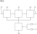
- FIG. 3 shows a schematic flowchart of the process.
- the RGB value 103 of the input signal 102 is normalized in step 200, taking into account the gamma characteristic, in particular the gamma value 104, of the display device 101 for the subsequent calculation.
- the standardized RGB value 115 is multiplied by the adjustment matrix 105 and the correction value 109 is added for correcting the black color location.
- the output value 106 is transformed back to the corresponding color depth Display device 101 taking into account the gamma value 104.
- a further correction value or further correction values are provided before the inverse transformation in step 203.
- a temperature correction value 111 is provided.
- a viewing angle correction value 112 can be provided.
- an ambient temperature at the display device 101 or an ambient temperature at the display device 113 is determined.
- the temperature correction value 111 is provided for the display device 101 and the display device 113.
- the RGB value 103 is therefore also corrected with regard to different display behavior of the display devices 101 and 113 when ambient temperatures change. This ensures that the same colors are displayed on the two display devices 101 and 113 with the same input signals 102 and 114, regardless of the ambient temperature.
- an viewing angle of the display device is determined.
- the viewing angle is determined in real time. This is done, for example, via cameras that are arranged inside the motor vehicle 100 and that are aimed at the driver. Using evaluation logic, the driver's viewing angle can be determined from the video signal from the camera. Alternatively, the system is calibrated once and a viewing angle is stored, for example, in the arrangement 116. For example, the installation position of the display devices 101 and 113 relative to the driver's seat is taken into account.
- the viewing angle correction value 112 Using the viewing angle correction value 112, a different perception of the display of the display devices 101 and 113 depending on the viewing angle is taken into account. For example, a displayed color of the display device 113 appears different depending on whether a viewer looks vertically at the display device 113 or obliquely.
- the display device 101 In the motor vehicle 100, the display device 101 is arranged, for example, directly in front of the driver in the instrument cluster.
- the display device 113 is arranged, for example, at an angle to the driver in the center console.
- the driver's different viewing angles on the display devices 101 and 113 are taken into account by the viewing angle correction value 112, so that the colors on the display devices 101 and 113 are each displayed in such a way that they appear the same to the driver.
- Figure 4A shows a color triangle 117 of the display device 101 and a color triangle 118 of the display device 113.
- Figure 4A shows the representation of the RGB value 103 without the correction method according to the application.
- the representation 119 on the display device 101 and the representation 120 on the display device 113 have a deviation, although the same input signal 102 or 114 with the same RGB value 103 is present.
- the representations 119 and 120 in particular have a deviation from one another that is greater than a predetermined tolerance. In particular, there is no conventional normalization depending on the gamma value 104.
- Figure 4B shows a representation 121 of the display device 101 and a representation 122 of the display device 113, after which the RGB value 103 was processed using the method according to the application.
- Representations 121 and 122 are the same or very close to each other.
- a deviation of the representations 121 and 122 is in particular smaller than the specified tolerance.
- almost identical color locations are obtained for all colors. This makes it possible to match the display devices 101 and 113 in a common target color space.
- a very small deviation or the avoidance of deviations between the display devices 101 and 113 is possible.
- several parameter sets are specified for the correction values, in particular for different viewing angles of the driver, the front passenger or passengers in the rear and/or different temperatures. This ensures a reliable comparison of the color appearance of the display devices 101 and 113.
Landscapes
- Engineering & Computer Science (AREA)
- Multimedia (AREA)
- Signal Processing (AREA)
- Instrument Panels (AREA)
- Fittings On The Vehicle Exterior For Carrying Loads, And Devices For Holding Or Mounting Articles (AREA)
Description
- Die vorliegende Erfindung betrifft ein Verfahren zum Betreiben einer Anzeigevorrichtung und einer weiteren Anzeigevorrichtung, insbesondere in einem Kraftfahrzeug. Die Erfindung betrifft weiterhin eine Anordnung, die zum Durchführen des Verfahrens ausgebildet ist, sowie ein Kraftfahrzeug, das die Anordnung aufweist.
- Anzeigevorrichtungen, insbesondere Bildschirme (sogenannte Displays), können bei einem gleichen Eingangssignal leicht unterschiedliche Farben darstellen. Beispielsweise in Kraftfahrzeugen können mehrere Anzeigevorrichtungen vorgesehen sein, die meist recht nahe zueinander eingebaut sind. Daher können im Kraftfahrzeug für einen Nutzer auch schon leichte farbliche Differenzen als störend wirken.
- Aus der
US 2011/0157212 A1 ist ein Verfahren zum Betreiben einer Anzeigevorrichtung bekannt mit Bereitstellen eines Eingangssignals, das mindestens einen RGB-Wert umfasst, Bereitstellen eines Gammawertes der Anzeigevorrichtung, Bereitstellen einer Abgleichsmatrix, die den Farbraum der Anzeigevorrichtung auf den ermittelten Zielfarbraum abbildet, Normieren des RGB-Werts in Abhängigkeit von dem Gammawert, Multiplizieren des normierten RGB-Werts mit der Abgleichsmatrix und dadurch Ermitteln eines Ausgangswertes, Rücktransformieren des Ausgangswertes in Abhängigkeit von dem Gammawert und dadurch Ermitteln eines korrigierten RGB-Werts, und Bereitstellen eines Ausgangssignals für die Anzeigevorrichtung, das den korrigierten RGB-Wert umfasst. Aus der Publikation "Color Gamut Matching for Tiled Display Walls" von Grant Wallace et al. ist es bekannt, einen Zielfarbraum als Schnittmenge mehrerer Anzeigevorrichtungen zu definieren. Aus derUS 2008/0101695 A1 ist ein Verfahren zur Farbwiedergabekorrektur bekannt. Aus derDE 103 55 462 A1 ist ein optisches Anzeigesystem für ein Fahrzeug bekannt. Die Publikation "Investigation on Color Shifts for Different Gamma of Display System in CIECAM02-Based Uniform Color Space" von Ping He et al. untersucht Farbverschiebungen bei unterschiedlichen Gamma-Werten. DieUS 8,860,745 B2 betrifft Farbgamutanpassungen. DieWO 2013/008282 A1 betrifft Blickwinkelkorrektur, dieCN 1845232 A betrifft Farbtemperaturkorrekturen. - Es ist wünschenswert, ein Verfahren zum Betreiben einer Anzeigevorrichtung und einer weiteren Anzeigevorrichtung anzugeben, das ein verlässliches Betreiben der Anzeigevorrichtungen ermöglicht. Insbesondere ist es Aufgabe der Erfindung, anzugeben, wie die Anzeigevorrichtungen temperaturunabhängig die gleichen Farben darstellen. Zudem ist es wünschenswert, eine Anordnung anzugeben, die dazu ausgebildet ist, das Verfahren auszuführen sowie ein Kraftfahrzeug, das eine derartige Anordnung aufweist.
- Eine erfindungsgemäße Lösung dazu ist in Anspruch 1, sowie in Anspruch 4 und 5 angegeben. Erfindungsgemäß wird für beide Anzeigevorrichtungen eine Umgebungstemperatur ermittelt, und in Abhängigkeit von der Umgebungstemperatur ein weiterer Korrekturwert, der Temperatur-Korrekturwert, bereitgestellt und angewendet.
- Gemäß zumindest einer Ausführungsform der Erfindung umfasst ein Verfahren zum Betreiben einer Anzeigevorrichtung und einer weiteren Anzeigevorrichtung ein Bereitstellen je eines Eingangssignals für die Anzeigevorrichtungen, das mindestens einen RGB-Wert umfasst. Ein Gammawert der jeweiligen Anzeigevorrichtung wird bereitgestellt. Eine Abgleichmatrix der jeweiligen Anzeigevorrichtung wird bereitgestellt. Der RGB-Wert wird in Abhängigkeit von dem Gammawert normiert. Der normierte RGB-Wert wird mit der Abgleichsmatrix multipliziert und dadurch ein Ausgangswert ermittelt. Der Ausgangswert wird in Abhängigkeit von dem Gammawert rücktransformiert und dadurch wird ein korrigierter RGB-Wert ermittelt. Ein Ausgangssignal für die jeweilige Anzeigevorrichtung wird bereitgestellt, das den korrigierten RGB-Wert umfasst.
- Das Eingangssignal wird somit unter Berücksichtigung des Gammawerts der jeweiligen Anzeigevorrichtung korrigiert. Somit ergibt sich insbesondere auch bei der Darstellung von Kombinationen der Grundfarben (Rot, Grün, Blau) auf unterschiedlichen Anzeigevorrichtungen die gleiche Farbe oder zumindest eine sehr ähnliche Farbe innerhalb von engen Toleranzen.
- Das Eingangssignal, das den mindestens einen RGB-Wert umfasst, ist insbesondere ein Signal zur Übertragung von Farbvideosignalen. Die drei Grundfarben Rot, Grün und Blau werden jeweils einzeln übertragen. Der Gammawert der jeweiligen Anzeigevorrichtung steht insbesondere für die exponentielle Helligkeitscharakteristik der jeweiligen Anzeigevorrichtung. Somit werden vom Menschen bei unterschiedlichen Farben empfundene Helligkeiten berücksichtigt und insbesondere ausgeglichen. Bei einem linear arbeitenden Anzeigegerät, wie beispielsweise den Anzeigevorrichtungen, muss das Eingangssignal mit dem Gammawert korrigiert werden, um ein lineares Wahrnehmen durch einen Nutzer zu ermöglichen. Ein typischer Gammawert für die Anzeigevorrichtungen ist beispielsweise 2,2.
- Erfindungsgemäß wird eine Umgebungstemperatur der jeweiligen Anzeigevorrichtung ermittelt. Ein jeweiliger Temperaturkorrekturwert wird in Abhängigkeit der ermittelten Umgebungstemperatur bereitgestellt. Der jeweilige Temperaturkorrekturwert wird auf dem ermittelten Ausgangswert vor dem Rücktransformieren angewendet. Somit werden auch unterschiedliche Farbdarstellungen ausgeglichen, die aus einem unterschiedlichen Verhalten der jeweiligen Anzeigevorrichtung bei unterschiedlichen Temperaturen resultieren. Somit ist es möglich, eine Farbe auch bei stark unterschiedlichen Temperaturen von bis zu -20° C bis + 40° C stets gleich oder möglichst gleich auf der jeweiligen Anzeigevorrichtung darzustellen.
- Gemäß Ausführungsformen wird ein Korrekturwert für eine Schwarzwertkorrektur des RGB-Werts bereitgestellt. Der Korrekturwert wird von dem ermittelten Ausgangswert subtrahiert. Nachfolgend erfolgt das Rücktransformieren in Abhängigkeit von dem Gammawert und das Ermitteln des korrigierten RGB-Werts. Somit ist auch eine verlässliche Anzeige von Schwarz auf der Anzeigevorrichtung möglich, wobei Schwarz im RGB-Farbraum ein sehr dunkles Grau ist.
- Gemäß weiteren Ausführungsformen wird ein Blickwinkel auf die Anzeigevorrichtung ermittelt. Ein Blickwinkelkorrekturwert wird in Abhängigkeit von dem ermittelten Blickwinkel bereitgestellt. Der Blickwinkelkorrekturwert wird auf dem ermittelten Ausgangswert vor dem Rücktransformieren angewendet. Somit wird auch eine unterschiedliche Farbwahrnehmung ausgeglichen, die aufgrund von unterschiedlichen Blickwinkeln entsteht. Beispielsweise in einem Kraftfahrzeug wird so berücksichtigt, ob die Anzeigevorrichtung unmittelbar vor dem Fahrer angeordnet ist, sodass ein Blickwinkel von im Wesentlichen 90° vorliegt, oder ob die Anzeigevorrichtung seitlich vom Fahrer angeordnet ist, beispielsweise in der Mittelkonsole, und der Fahrer daher schräg auf die Anzeigevorrichtung blickt. Entsprechend ist auch eine Berücksichtigung des Blickwinkels für andere Nutzer möglich, beispielweise einem Beifahrer.
- Erfindungsgemäß wird das Verfahren verwendet, um mindestens eine weitere Anzeigevorrichtung zu betreiben. Das Verfahren ist insbesondere geeignet, zwei Anzeigevorrichtungen oder mehr zu betreiben. Für die weitere Anzeigevorrichtung wird ein weiteres Eingangssignal bereitgestellt, das den mindestens einen RGB-Wert umfasst. Ein weiterer Gammawert der weiteren Anzeigevorrichtung wird bereitgestellt. Eine weitere Abgleichmatrix der weiteren Anzeigevorrichtung wird bereitgestellt. Der RGB-Wert wird in Abhängigkeit von dem weiteren Gammawert normiert. Der weitere normierte RGB-Wert wird mit der weiteren Abgleichmatrix multipliziert und dadurch ein weiterer Ausgangswert ermittelt. Der weitere Ausgangswert wird in Abhängigkeit von dem weiteren Gammawert rücktransformiert und dadurch ein weiterer korrigierter RGB-Wert ermittelt. Ein weiteres Ausgangssignal für die weitere Anzeigevorrichtung wird bereitgestellt, das den weiteren korrigierten RGB-Wert umfasst. Ein dem korrigierten RGB-Wert zugehöriger Farbort der Anzeigevorrichtung und ein dem weiteren korrigierten RGB-Wert zugehöriger weiterer Farbort der weiteren Anzeigevorrichtung sind im Wesentlichen gleich. Insbesondere sind die beiden Farborte gleich oder innerhalb von vorgegebenen Toleranzen sehr ähnlich. Somit ist es möglich, dass die mehreren Anzeigevorrichtungen bei denselben Eingangsdaten den gleichen Farbort darstellen. Beispielsweise wenn Bildinhalte von einer Anzeigevorrichtung zu der weiteren Anzeigevorrichtung geschoben werden, wird somit eine einheitliche Wahrnehmung ermöglicht und störende farbliche Differenzen werden vermieden.
- Weitere Merkmale, Vorteile und Weiterbildungen ergeben sich aus den nachfolgenden in Verbindung mit den Figuren erläuterten Beispielen. Gleiche, gleichartige und gleich wirkende Elemente können dabei mit den gleichen Bezugszeichen versehen sein.
- Es zeigen:
- Figur 1
- eine schematische Darstellung eines Kraftfahrzeugs gemäß Ausführungsformen,
- Figur 2
- eine schematische Darstellung eines Verfahrens gemäß Ausführungsformen,
- Figur 3
- eine schematische Darstellung eines Flussdiagramms gemäß Ausführungsformen und
- Figuren 4A und 4B
- den Vergleich von zwei Anzeigevorrichtungen auf einer Farbtafel gemäß Ausführungsformen.
-
Figur 1 zeigt ein Kraftfahrzeug 100, insbesondere einen Personenkraftwagen. Das Kraftfahrzeug 100 weist zwei Anzeigevorrichtungen 101, 113 auf. Gemäß weiteren Ausführungsformen weist das Kraftfahrzeug 100 mehr als zwei Anzeigevorrichtungen auf. Die Anzeigevorrichtungen basieren gemäß Ausführungsformen auf der gleichen Technologie oder haben gemäß weiteren Ausführungsformen unterschiedliche Technologien, beispielsweise OLED, IPS, MVA, TN oder weitere Technologien. Eine Anordnung 116 ist vorgesehen, die dazu ausgebildet ist, Eingangssignale 102, 114 für die Anzeigevorrichtungen 101, 113 umzuwandeln und Ausgangssignale 108, 120 für die Anzeigevorrichtungen 101, 113 zur Verfügung zu stellen. Mittels der Anordnung 116 ist ein Farbabgleich für die Anzeigevorrichtungen 101, 113 auf einem gemeinsamen Zielfarbraum möglich. Die Eingangssignale 102, 114 werden mittels der Anordnung 116 insbesondere in Echtzeit so angepasst, dass die Anzeigevorrichtungen 101, 113 bei denselben Eingangssignalen 102, 114 die gleichen Farben darstellen. Das Eingangssignal 102 und das Ausgangssignal 108 sind der Anzeigevorrichtung 101 zugeordnet. Das Eingangssignal 114 und das Ausgangssignal 120 sind der Anzeigevorrichtung 113 zugeordnet. - Die Eingangssignale 102 und 118 umfassen jeweils den gleichen RGB-Wert 103 (
Figur 2 ). Der RGB-Wert gibt vor, welche Farbe auf der Anzeigevorrichtung 101 und der Anzeigevorrichtung 113 angezeigt werden soll.Figur 2 zeigt dabei exemplarisch die Umrechnung für die Anzeigevorrichtung 101. Die Umrechnung für die Anzeigevorrichtung 113 erfolgt analog, wobei die der Anzeigevorrichtung 113 zugeordneten Korrekturfaktoren anstelle der der Anzeigevorrichtung 101 zugeordneten Korrekturfaktoren verwendet werden. - Der RGB-Wert 103 des Eingangssignals 102 wird mit einem Gammawert 104 normiert. Das Ergebnis der Normierung mit dem Gammawert 104 ist ein normierter RGB-Wert 115. Der Gammawert 104 ist für die Anzeigevorrichtung 101 vorgegeben und beispielsweise in der Anordnung 116 hinterlegt. Der Gammawert ist beispielsweise von der Technologie der Anzeigevorrichtung 101 abhängig.
- Der normierte RGB-Wert 115 wird mit einer Abgleichsmatrix 105 multipliziert. Die Abgleichsmatrix 105 dient insbesondere dazu, die von der Anzeigevorrichtung 101 anzeigbaren Farben auf einen Zielfarbraum umzurechnen. Der Zielfarbraum ist in Abhängigkeit von den beiden Anzeigevorrichtungen 101 und 113 vorgegeben. Der Zielfarbraum ist insbesondere der Farbraum, der von beiden Anzeigevorrichtungen 101 und 113 darstellbar ist. In einer Normtafel nach DIN 5033 lassen sich die von den Anzeigevorrichtungen 101 und 113 darstellbaren Farben durch Dreiecke symbolisieren, die den darstellbaren Farbraum eingrenzen. Liegt beispielsweise das Farbdreieck der Anzeigevorrichtung 101 in dem Farbdreieck der Anzeigevorrichtung 113, wird als Zielfarbraum für beide Anzeigevorrichtungen 101 und 113 der Farbraum der Anzeigevorrichtung 101 gewählt. Überlappen die beiden Farbdreiecke der Anzeigevorrichtungen 101 und 113 nur teilweise und teilweise nicht, wird als Zielfarbraum der Bereich gewählt, in dem die beiden Farbdreiecke überlappen.
- Zu dem Produkt aus normierten RGB-Wert 115 und Abgleichsmatrix 105 wird ein Korrekturwert 109 für eine Schwarzwertkorrektur addiert. Dies dient zur möglichst gleichen Darstellung grauer und nahezu schwarzer RGB-Werte auf den Anzeigevorrichtungen 101 und 113. Als Ergebnis wird ein Ausgangswert 106 ermittelt. Unter Berücksichtigung des Gammawerts 104 wird der Ausgangswert 106 wieder zurück in die RGB-Welt transformiert und als korrigierter RGB-Wert 107 an die Anzeigevorrichtung 101 ausgegeben.
- Das Verfahren und die einzelnen Rechenschritte erfolgen in der Anordnung 116 insbesondere in Echtzeit.
-
Figur 3 zeigt schematisch ein Flussdiagramm des Verfahrens. Der RGB-Wert 103 des Eingangssignals 102 wird im Schritt 200 unter Berücksichtigung der Gammacharakteristik, insbesondere des Gammawerts 104, der Anzeigevorrichtung 101 für die nachfolgende Berechnung normiert. In Schritt 201 erfolgt die Multiplikation des normierten RGB-Werts 115 mit der Abgleichmatrix 105 und die Addition des Korrekturwerts 109 für die Korrektur des Schwarzfarborts. In Schritt 202 erfolgt das Rücktransformieren des Ausgangswerts 106 auf die entsprechende Farbtiefe der Anzeigevorrichtung 101 unter Berücksichtigung des Gammawerts 104. - Zusätzlich wird gemäß Ausführungsbeispielen vor dem Rücktransformieren in Schritt 203 ein weiterer Korrekturwert oder weitere Korrekturwerte bereitgestellt. Erfindungsgemäß wird ein Temperaturkorrekturwert 111 bereitgestellt. Zusätzlich kann beispielsweise ein Blickwinkelkorrekturwert 112 bereitgestellt werden.
- Zum Bereitstellen des Temperaturkorrekturwerts 111 wird eine Umgebungstemperatur an der Anzeigevorrichtung 101 beziehungsweise eine Umgebungstemperatur an der Anzeigevorrichtung 113 ermittelt. In Abhängigkeit der ermittelten Temperatur wird der Temperaturkorrekturwert 111 jeweils für die Anzeigevorrichtung 101 und die Anzeigevorrichtung 113 bereitgestellt. Somit wird der RGB-Wert 103 auch im Hinblick auf ein unterschiedliches Darstellungsverhalten der Anzeigevorrichtungen 101 und 113 bei sich ändernden Umgebungstemperaturen korrigiert. Somit ist gewährleistet, dass unabhängig von der Umgebungstemperatur auf den beiden Anzeigevorrichtungen 101 und 113 bei denselben Eingangssignalen 102 und 114 die gleichen Farben dargestellt werden.
- Zum Bereitstellen des Blickwinkelkorrekturwerts 112 wird insbesondere ein Blickwinkel auf die Anzeigevorrichtung ermittelt. Der Blickwinkel wird beispielsweise in Echtzeit ermittelt. Dies erfolgt beispielsweise über Kameras, die im Inneren des Kraftfahrzeugs 100 angeordnet sind, und die auf den Fahrer gerichtet sind. Mittels einer Auswertelogik kann aus dem Videosignal der Kamera der Blickwinkel des Fahrers ermittelt werden. Alternativ wird das System einmalig kalibriert und ein Blickwinkel beispielsweise in der Anordnung 116 hinterlegt. Dabei wird beispielsweise die Einbauposition der Anzeigevorrichtungen 101 und 113 relativ zum Fahrersitz berücksichtigt.
- Mittels des Blickwinkelkorrekturwerts 112 wird eine unterschiedliche Wahrnehmung der Anzeige der Anzeigevorrichtungen 101 und 113 in Abhängigkeit des Blickwinkels berücksichtigt. Beispielsweise wirkt eine dargestellte Farbe der Anzeigevorrichtung 113 unterschiedlich, je nachdem, ob ein Betrachter senkrecht auf die Anzeigevorrichtung 113 blickt oder schräg. Im Kraftfahrzeug 100 ist die Anzeigevorrichtung 101 beispielsweise unmittelbar vor dem Fahrer im Kombiinstrument angeordnet. Die Anzeigevorrichtung 113 ist beispielsweise schräg zum Fahrer in der Mittelkonsole angeordnet. Die unterschiedlichen Blickwinkel des Fahrers auf die Anzeigevorrichtungen 101 und 113 werden durch den Blickwinkelkorrekturwert 112 berücksichtigt, sodass die Farben auf den Anzeigevorrichtungen 101 und 113 jeweils so dargestellt werden, dass sie für den Fahrer gleich wirken.
-
Figur 4A zeigt ein Farbdreieck 117 der Anzeigevorrichtung 101 und ein Farbdreieck 118 der Anzeigevorrichtung 113.Figur 4A zeigt die Darstellung des RGB-Werts 103 ohne das anmeldungsgemäße Korrekturverfahren. Die Darstellung 119 auf der Anzeigevorrichtung 101 und die Darstellung 120 auf der Anzeigevorrichtung 113 weisen eine Abweichung auf, obwohl das gleiche Eingangssignal 102 beziehungsweise 114 mit dem gleichen RGB-Wert 103 vorliegt. Die Darstellungen 119 und 120 weisen insbesondere eine Abweichung voneinander auf, die größer als eine vorgegebene Toleranz ist. Insbesondere erfolgt herkömmlich keine Normierung in Abhängigkeit von dem Gammawert 104. -
Figur 4B zeigt eine Darstellung 121 der Anzeigevorrichtung 101 und eine Darstellung 122 der Anzeigevorrichtung 113, nach dem der RGB-Wert 103 mittels des anmeldungsgemäßen Verfahrens bearbeitet wurde. Die Darstellungen 121 und 122 sind gleich beziehungsweise liegen sehr nahe beieinander. Eine Abweichung der Darstellungen 121 und 122 ist insbesondere kleiner als die vorgegebene Toleranz. Bei allen Farben stellt sich nach dem Abgleich mit dem anmeldungsgemäßen Verfahren nahezu der identische Farbort ein. Somit ist ein Farbabgleich der Anzeigevorrichtungen 101 und 113 auf einem gemeinsamen Zielfarbraum möglich. Insbesondere bei der Darstellung von Kombinationen der Grundfarben ist eine sehr geringe Abweichung beziehungsweise das Vermeiden von Abweichungen zwischen den Anzeigevorrichtungen 101 und 113 möglich. Gemäß Ausführungsbeispielen werden mehrere Parametersätze für die Korrekturwerte vorgegeben, insbesondere für verschiedene Blickwinkel des Fahrers, des Beifahrers oder Passagieren im Fond und/oder verschiedene Temperaturen. Somit ist ein verlässlicher Abgleich der farblichen Anmutung der Anzeigevorrichtungen 101 und 113 gegeben.
Claims (5)
- Verfahren zum Betreiben einer Anzeigevorrichtung (101) und einer weiteren Anzeigevorrichtung (113), umfassend:- Bereitstellen eines Eingangssignals (102), das mindestens einen RGB-Wert (103) umfasst,- Bereitstellen eines Gammawertes (104) der Anzeigevorrichtung,- Ermitteln eines Zielfarbraums für die Anzeigevorrichtung (101) in Abhängigkeit vom Farbraum der weiteren Anzeigevorrichtung (113) gemäß- liegt der Farbraum einer der beiden Anzeigevorrichtungen (101,113)in dem Farbraum der anderen Anzeigevorrichtung (113,101) , so wird als Zielfarbraum der Farbraum gewählt, der in dem anderen Farbraum liegt,- überlappen die Farbräume der beiden Anzeigevorrichtungen (101,113) nur teilweise und teilweise nicht, so wird als Zielfarbraum der Bereich gewählt, in dem die beiden Farbräume überlappen,- Bereitstellen einer Abgleichsmatrix (105), die den Farbraum der Anzeigevorrichtung auf den ermittelten Zielfarbraum abbildet,- Normieren (200) des RGB-Werts (103) in Abhängigkeit von dem Gammawert (104),- Multiplizieren (201) des normierten RGB-Werts (115) mit der Abgleichsmatrix (105) und dadurch Ermitteln eines Ausgangswertes (106),- Rücktransformieren (202) des Ausgangswertes (106) in Abhängigkeit von dem Gammawert (104) und dadurch Ermitteln eines korrigierten RGB-Werts (107),- Bereitstellen eines Ausgangssignals (108) für die Anzeigevorrichtung, das den korrigierten RGB-Wert (107) umfasst,- Bereitstellen eines weiteren Eingangssignals (114), das mindestens einen RGB-Wert (103) umfasst,- Bereitstellen eines weiteren Gammawertes (104) der weiteren Anzeigevorrichtung (113),- Bereitstellen einer Abgleichsmatrix (105), die den Farbraum der weiteren Anzeigevorrichtung (113) auf den ermittelten Zielfarbraum derart abbildet, daß bei identischen RGB-Werten (103) des Eingangssignals (102) und des weiteren Eingangssignals (114) ein dem korrigierten RGB-Wert (107) zugehöriger Farbort der Anzeigvorrichtung (101) und ein dem weiteren korrigierten RGB-Wert (107) zugehöriger weiterer Farbort der weiteren Anzeigevorrichtung (113) gleich sind,- Normieren (200) des RGB-Werts (103) in Abhängigkeit von dem weiteren Gammawert,- Multiplizieren (201) des weiteren normierten RGB-Werts (115) mit der weiteren Abgleichsmatrix (105) und dadurch Ermitteln eines weiteren Ausgangswertes (106),- Rücktransformieren (202) des weiteren Ausgangswertes (106) in Abhängigkeit von dem weiteren Gammawert und dadurch Ermitteln eines weiteren korrigierten RGB-Werts (107),- Bereitstellen eines weiteren Ausgangssignals (120) für die weitere Anzeigevorrichtung (113), das den weiteren korrigierten RGB-Wert (107) umfasst,weiterhin umfassend:- Ermitteln einer Umgebungstemperatur an der Anzeigevorrichtung (101),- Bereitstellen (203) eines Temperatur-Korrekturwerts (111) für die Anzeigevorrichtung (101) in Abhängigkeit der ermittelten Umgebungstemperatur,- Anwenden des Temperatur-Korrekturwertes (111) auf den ermittelten Ausgangswert vor dem Rücktransformieren,- Ermitteln einer Umgebungstemperatur an der weiteren Anzeigevorrichtung (113),- Bereitstellen (203) eines weiteren Temperatur-Korrekturwerts (111) für die weitere Anzeigevorrichtung (113) in Abhängigkeit der ermittelten Umgebungstemperatur,- Anwenden des weiteren Temperatur-Korrekturwertes (111) auf den ermittelten weiteren Ausgangswert für die weitere Anzeigevorrichtung (113) vor dem Rücktransformieren.
- Verfahren nach Anspruch 1, umfassend:- Bereitstellen eines Korrekturwertes (109) für eine Schwarzwert-Korrektur des RGB-Werts,- Addieren des Korrekturwertes (109) zu dem Produkt aus normiertem RGB-Wert (115) und Abgleichsmatrix (105) zum Ermitteln eines Ausgangswerts (106) vor dem Rücktransformieren.
- Verfahren nach einem der Ansprüche 1 bis 2, umfassend:- Ermitteln eines Blickwinkels auf die Anzeigevorrichtung,- Bereitstellen eines Blickwinkel-Korrekturwerts (112) in Abhängigkeit von dem ermittelten Blickwinkel,- Anwenden des Blinkwinkel-Korrekturwertes (112) auf den ermittelten Ausgangswert vor dem Rücktransformieren.
- Anordnung (116) zum Betreiben zweier Anzeigevorrichtungen (101,113), wobei die Anordnung (116) dazu ausgebildet ist, Eingangssignale (102,114) für die Anzeigevorrichtungen (101,113) gemäß einem Verfahren nach einem der Ansprüche 1 bis 3 in Ausgangssignale (108,120) für die Anzeigevorrichtungen (101,113) umzuwandeln.
- Kraftfahrzeug, aufweisend:- eine Anordnung (116) nach Anspruch 4,- die Anzeigevorrichtungen (101,113).
Applications Claiming Priority (2)
| Application Number | Priority Date | Filing Date | Title |
|---|---|---|---|
| DE102014221057.7A DE102014221057A1 (de) | 2014-10-16 | 2014-10-16 | Verfahren zum Betreiben einer Anzeigevorrichtung, Anordnung und Kraftfahrzeug |
| PCT/EP2015/073881 WO2016059156A1 (de) | 2014-10-16 | 2015-10-15 | Verfahren zum betreiben einer anzeigevorrichtung, anordnung und kraftfahrzeug |
Publications (2)
| Publication Number | Publication Date |
|---|---|
| EP3207694A1 EP3207694A1 (de) | 2017-08-23 |
| EP3207694B1 true EP3207694B1 (de) | 2023-09-13 |
Family
ID=54347494
Family Applications (1)
| Application Number | Title | Priority Date | Filing Date |
|---|---|---|---|
| EP15784603.1A Active EP3207694B1 (de) | 2014-10-16 | 2015-10-15 | Verfahren zum betreiben einer anzeigevorrichtung, anordnung und kraftfahrzeug |
Country Status (3)
| Country | Link |
|---|---|
| EP (1) | EP3207694B1 (de) |
| DE (1) | DE102014221057A1 (de) |
| WO (1) | WO2016059156A1 (de) |
Citations (2)
| Publication number | Priority date | Publication date | Assignee | Title |
|---|---|---|---|---|
| CN1845232A (zh) * | 2005-04-08 | 2006-10-11 | 浙江大学 | 液晶显示器gamma曲线与色温自动测量和校正方法及系统 |
| WO2013008282A1 (ja) * | 2011-07-08 | 2013-01-17 | Necディスプレイソリューションズ株式会社 | 視野角補正装置、視野角補正方法および視野角補正プログラム |
Family Cites Families (11)
| Publication number | Priority date | Publication date | Assignee | Title |
|---|---|---|---|---|
| US6775633B2 (en) * | 2001-12-31 | 2004-08-10 | Kodak Polychrome Graphics, Llc | Calibration techniques for imaging devices |
| US7397485B2 (en) * | 2002-12-16 | 2008-07-08 | Eastman Kodak Company | Color OLED display system having improved performance |
| DE10355462A1 (de) * | 2003-11-27 | 2005-06-23 | Daimlerchrysler Ag | Optisches Anzeigesystem für ein Fahrzeug |
| JP2008109328A (ja) * | 2006-10-25 | 2008-05-08 | Infovision Optoelectronics Holdings Ltd | 色再現域補正回路と補正方法 |
| US8860745B2 (en) * | 2009-06-01 | 2014-10-14 | Stmicroelectronics, Inc. | System and method for color gamut mapping |
| US8654141B2 (en) * | 2009-12-29 | 2014-02-18 | Intel Corporation | Techniques for adapting a color gamut |
| US8704859B2 (en) * | 2010-09-30 | 2014-04-22 | Apple Inc. | Dynamic display adjustment based on ambient conditions |
| WO2012107152A1 (en) * | 2011-02-10 | 2012-08-16 | Thomson Licensing | Color calibration of a 3d display system comprising a 3d display device and 3d glasses |
| DE102011007518A1 (de) * | 2011-04-15 | 2012-10-18 | Robert Bosch Gmbh | Anzeigevorrichtung für Kraftfahrzeuge |
| DE102011088760A1 (de) * | 2011-12-15 | 2013-06-20 | Robert Bosch Gmbh | Anzeigevorrichtung |
| US20140292616A1 (en) * | 2013-03-28 | 2014-10-02 | Nvidia Corporation | Computer monitor equalization using handheld device |
-
2014
- 2014-10-16 DE DE102014221057.7A patent/DE102014221057A1/de active Pending
-
2015
- 2015-10-15 WO PCT/EP2015/073881 patent/WO2016059156A1/de not_active Ceased
- 2015-10-15 EP EP15784603.1A patent/EP3207694B1/de active Active
Patent Citations (2)
| Publication number | Priority date | Publication date | Assignee | Title |
|---|---|---|---|---|
| CN1845232A (zh) * | 2005-04-08 | 2006-10-11 | 浙江大学 | 液晶显示器gamma曲线与色温自动测量和校正方法及系统 |
| WO2013008282A1 (ja) * | 2011-07-08 | 2013-01-17 | Necディスプレイソリューションズ株式会社 | 視野角補正装置、視野角補正方法および視野角補正プログラム |
Also Published As
| Publication number | Publication date |
|---|---|
| DE102014221057A1 (de) | 2016-04-21 |
| WO2016059156A1 (de) | 2016-04-21 |
| EP3207694A1 (de) | 2017-08-23 |
Similar Documents
| Publication | Publication Date | Title |
|---|---|---|
| DE102012025322A1 (de) | Kraftfahrzeug mit Kamera-Monitor-System | |
| DE102015206477A1 (de) | Verfahren zur Darstellung einer Fahrzeugumgebung eines Fahrzeuges | |
| DE102016225066A1 (de) | Rundumsichtsystem für ein Fahrzeug | |
| DE102013020950A1 (de) | Verfahren zum Betreiben eines Rückansichtskamerasystems eines Kraftfahrzeugs, Rückansichtskamerasystem und Kraftfahrzeug | |
| DE102013021711A1 (de) | Angleichung von Computerbildschirmen unter Verwendung eines Handgerätes | |
| DE102011010859B4 (de) | Verfahren zum Betreiben eines Kamerasystems in einem Kraftfahrzeug, Kamerasystem und Kraftfahrzeug | |
| DE102014006153A1 (de) | Verfahren zur Bilddarstellung eines indirekten Sichtfeldes im Fahrzeugumfeld eines Fahrzeugs, insbesondere eines Nutzfahrzeugs, mit einem Kamera-Monitor-System | |
| DE102011007518A1 (de) | Anzeigevorrichtung für Kraftfahrzeuge | |
| WO2016165799A1 (de) | Verfahren zum betreiben einer virtual-reality-brille und system mit einer virtual-reality-brille | |
| DE102020134814A1 (de) | Vorrichtung zum Überwachen von Umgebungen eines Fahrzeugs | |
| DE102014116441A1 (de) | Verfahren zum Darstellen einer Sicherheitsinformation, Fahrerassistenzsystem und Kraftfahrzeug | |
| DE102017000674B3 (de) | Visuelle Unterstützung einer manuellen Kalibrierung eines Head-Up-Displays in einem Fahrzeug | |
| DE102015105529A1 (de) | Verfahren zum Transformieren eines Bildes einer virtuellen Kamera, Computerprogrammprodukt, Anzeigesystem und Kraftfahrzeug | |
| EP2816802A1 (de) | Verfahren und Vorrichtung zum Anpassen eines Bildparameters | |
| DE102018110597B4 (de) | Verfahren zur Bildharmonisierung, Bildverarbeitungseinrichtung, Kamerasystem und Kraftfahrzeug | |
| DE102016115128A1 (de) | Verfahren zum Angleichen zumindest zweier Bilder bezüglich der Farbe und/oder der Helligkeit, Kamarasystem sowie Kraftfahrzeug | |
| DE102014221057A1 (de) | Verfahren zum Betreiben einer Anzeigevorrichtung, Anordnung und Kraftfahrzeug | |
| EP1206123B1 (de) | Verfahren zur Falschfarbendarstellung von Bildinformation | |
| DE102012016865A1 (de) | Verbessertes Alpha-Blending von Bildern eines Kamerasystems eines Kraftfahrzeugs | |
| DE102014219418B4 (de) | Verfahren zur Stereorektifizierung von Stereokamerabildern und Fahrerassistenzsystem | |
| DE102012007982A1 (de) | Verfahren zum Weißabgleich eines Bildes unter Berücksichtigung der Farbgebung des Kraftfahrzeugs | |
| DE102021126187A1 (de) | Anzeigeverfahren sowie transparente Anzeigevorrichtung, Fahrerassistenzsystem und Fortbewegungsmittel zum Ausführen des Anzeigeverfahrens | |
| DE60212441T2 (de) | Farbkalibrierung | |
| DE102016124315A1 (de) | Kamerabefestigungseinrichtung, Kamerasystem, Kraftfahrzeuganhänger, Kraftfahrzeug und Verfahren zum Befestigen einer Kamera an einem Kraftfahrzeuganhänger | |
| DE102012201805A1 (de) | Vorrichtung und Verfahren zum Bestimmen eines Kompensationsparameters für ein Übersprechen bei einem mehrsichtbetriebsfähigen Anzeigegerät |
Legal Events
| Date | Code | Title | Description |
|---|---|---|---|
| STAA | Information on the status of an ep patent application or granted ep patent |
Free format text: STATUS: THE INTERNATIONAL PUBLICATION HAS BEEN MADE |
|
| PUAI | Public reference made under article 153(3) epc to a published international application that has entered the european phase |
Free format text: ORIGINAL CODE: 0009012 |
|
| STAA | Information on the status of an ep patent application or granted ep patent |
Free format text: STATUS: REQUEST FOR EXAMINATION WAS MADE |
|
| 17P | Request for examination filed |
Effective date: 20170516 |
|
| AK | Designated contracting states |
Kind code of ref document: A1 Designated state(s): AL AT BE BG CH CY CZ DE DK EE ES FI FR GB GR HR HU IE IS IT LI LT LU LV MC MK MT NL NO PL PT RO RS SE SI SK SM TR |
|
| AX | Request for extension of the european patent |
Extension state: BA ME |
|
| DAV | Request for validation of the european patent (deleted) | ||
| DAX | Request for extension of the european patent (deleted) | ||
| RAP1 | Party data changed (applicant data changed or rights of an application transferred) |
Owner name: CONTINENTAL AUTOMOTIVE GMBH |
|
| STAA | Information on the status of an ep patent application or granted ep patent |
Free format text: STATUS: EXAMINATION IS IN PROGRESS |
|
| 17Q | First examination report despatched |
Effective date: 20201021 |
|
| RAP1 | Party data changed (applicant data changed or rights of an application transferred) |
Owner name: CONTINENTAL AUTOMOTIVE TECHNOLOGIES GMBH |
|
| GRAP | Despatch of communication of intention to grant a patent |
Free format text: ORIGINAL CODE: EPIDOSNIGR1 |
|
| STAA | Information on the status of an ep patent application or granted ep patent |
Free format text: STATUS: GRANT OF PATENT IS INTENDED |
|
| INTG | Intention to grant announced |
Effective date: 20230508 |
|
| P01 | Opt-out of the competence of the unified patent court (upc) registered |
Effective date: 20230522 |
|
| GRAS | Grant fee paid |
Free format text: ORIGINAL CODE: EPIDOSNIGR3 |
|
| GRAA | (expected) grant |
Free format text: ORIGINAL CODE: 0009210 |
|
| STAA | Information on the status of an ep patent application or granted ep patent |
Free format text: STATUS: THE PATENT HAS BEEN GRANTED |
|
| AK | Designated contracting states |
Kind code of ref document: B1 Designated state(s): AL AT BE BG CH CY CZ DE DK EE ES FI FR GB GR HR HU IE IS IT LI LT LU LV MC MK MT NL NO PL PT RO RS SE SI SK SM TR |
|
| REG | Reference to a national code |
Ref country code: GB Ref legal event code: FG4D Free format text: NOT ENGLISH |
|
| REG | Reference to a national code |
Ref country code: CH Ref legal event code: EP |
|
| REG | Reference to a national code |
Ref country code: DE Ref legal event code: R096 Ref document number: 502015016596 Country of ref document: DE |
|
| REG | Reference to a national code |
Ref country code: IE Ref legal event code: FG4D Free format text: LANGUAGE OF EP DOCUMENT: GERMAN |
|
| REG | Reference to a national code |
Ref country code: LT Ref legal event code: MG9D |
|
| REG | Reference to a national code |
Ref country code: NL Ref legal event code: MP Effective date: 20230913 |
|
| PG25 | Lapsed in a contracting state [announced via postgrant information from national office to epo] |
Ref country code: GR Free format text: LAPSE BECAUSE OF FAILURE TO SUBMIT A TRANSLATION OF THE DESCRIPTION OR TO PAY THE FEE WITHIN THE PRESCRIBED TIME-LIMIT Effective date: 20231214 |
|
| PG25 | Lapsed in a contracting state [announced via postgrant information from national office to epo] |
Ref country code: SE Free format text: LAPSE BECAUSE OF FAILURE TO SUBMIT A TRANSLATION OF THE DESCRIPTION OR TO PAY THE FEE WITHIN THE PRESCRIBED TIME-LIMIT Effective date: 20230913 Ref country code: RS Free format text: LAPSE BECAUSE OF FAILURE TO SUBMIT A TRANSLATION OF THE DESCRIPTION OR TO PAY THE FEE WITHIN THE PRESCRIBED TIME-LIMIT Effective date: 20230913 Ref country code: NO Free format text: LAPSE BECAUSE OF FAILURE TO SUBMIT A TRANSLATION OF THE DESCRIPTION OR TO PAY THE FEE WITHIN THE PRESCRIBED TIME-LIMIT Effective date: 20231213 Ref country code: LV Free format text: LAPSE BECAUSE OF FAILURE TO SUBMIT A TRANSLATION OF THE DESCRIPTION OR TO PAY THE FEE WITHIN THE PRESCRIBED TIME-LIMIT Effective date: 20230913 Ref country code: LT Free format text: LAPSE BECAUSE OF FAILURE TO SUBMIT A TRANSLATION OF THE DESCRIPTION OR TO PAY THE FEE WITHIN THE PRESCRIBED TIME-LIMIT Effective date: 20230913 Ref country code: HR Free format text: LAPSE BECAUSE OF FAILURE TO SUBMIT A TRANSLATION OF THE DESCRIPTION OR TO PAY THE FEE WITHIN THE PRESCRIBED TIME-LIMIT Effective date: 20230913 Ref country code: GR Free format text: LAPSE BECAUSE OF FAILURE TO SUBMIT A TRANSLATION OF THE DESCRIPTION OR TO PAY THE FEE WITHIN THE PRESCRIBED TIME-LIMIT Effective date: 20231214 Ref country code: FI Free format text: LAPSE BECAUSE OF FAILURE TO SUBMIT A TRANSLATION OF THE DESCRIPTION OR TO PAY THE FEE WITHIN THE PRESCRIBED TIME-LIMIT Effective date: 20230913 |
|
| REG | Reference to a national code |
Ref country code: DE Ref legal event code: R081 Ref document number: 502015016596 Country of ref document: DE Owner name: CONTINENTAL AUTOMOTIVE TECHNOLOGIES GMBH, DE Free format text: FORMER OWNER: CONTINENTAL AUTOMOTIVE TECHNOLOGIES GMBH, 30165 HANNOVER, DE Ref country code: DE Ref legal event code: R081 Ref document number: 502015016596 Country of ref document: DE Owner name: AUMOVIO GERMANY GMBH, DE Free format text: FORMER OWNER: CONTINENTAL AUTOMOTIVE TECHNOLOGIES GMBH, 30165 HANNOVER, DE |
|
| PG25 | Lapsed in a contracting state [announced via postgrant information from national office to epo] |
Ref country code: NL Free format text: LAPSE BECAUSE OF FAILURE TO SUBMIT A TRANSLATION OF THE DESCRIPTION OR TO PAY THE FEE WITHIN THE PRESCRIBED TIME-LIMIT Effective date: 20230913 |
|
| P02 | Opt-out of the competence of the unified patent court (upc) changed |
Effective date: 20240207 |
|
| PG25 | Lapsed in a contracting state [announced via postgrant information from national office to epo] |
Ref country code: IS Free format text: LAPSE BECAUSE OF FAILURE TO SUBMIT A TRANSLATION OF THE DESCRIPTION OR TO PAY THE FEE WITHIN THE PRESCRIBED TIME-LIMIT Effective date: 20240113 |
|
| RAP4 | Party data changed (patent owner data changed or rights of a patent transferred) |
Owner name: CONTINENTAL AUTOMOTIVE TECHNOLOGIES GMBH |
|
| PG25 | Lapsed in a contracting state [announced via postgrant information from national office to epo] |
Ref country code: ES Free format text: LAPSE BECAUSE OF FAILURE TO SUBMIT A TRANSLATION OF THE DESCRIPTION OR TO PAY THE FEE WITHIN THE PRESCRIBED TIME-LIMIT Effective date: 20230913 |
|
| PG25 | Lapsed in a contracting state [announced via postgrant information from national office to epo] |
Ref country code: SM Free format text: LAPSE BECAUSE OF FAILURE TO SUBMIT A TRANSLATION OF THE DESCRIPTION OR TO PAY THE FEE WITHIN THE PRESCRIBED TIME-LIMIT Effective date: 20230913 Ref country code: RO Free format text: LAPSE BECAUSE OF FAILURE TO SUBMIT A TRANSLATION OF THE DESCRIPTION OR TO PAY THE FEE WITHIN THE PRESCRIBED TIME-LIMIT Effective date: 20230913 Ref country code: IS Free format text: LAPSE BECAUSE OF FAILURE TO SUBMIT A TRANSLATION OF THE DESCRIPTION OR TO PAY THE FEE WITHIN THE PRESCRIBED TIME-LIMIT Effective date: 20240113 Ref country code: ES Free format text: LAPSE BECAUSE OF FAILURE TO SUBMIT A TRANSLATION OF THE DESCRIPTION OR TO PAY THE FEE WITHIN THE PRESCRIBED TIME-LIMIT Effective date: 20230913 Ref country code: EE Free format text: LAPSE BECAUSE OF FAILURE TO SUBMIT A TRANSLATION OF THE DESCRIPTION OR TO PAY THE FEE WITHIN THE PRESCRIBED TIME-LIMIT Effective date: 20230913 Ref country code: CZ Free format text: LAPSE BECAUSE OF FAILURE TO SUBMIT A TRANSLATION OF THE DESCRIPTION OR TO PAY THE FEE WITHIN THE PRESCRIBED TIME-LIMIT Effective date: 20230913 Ref country code: PT Free format text: LAPSE BECAUSE OF FAILURE TO SUBMIT A TRANSLATION OF THE DESCRIPTION OR TO PAY THE FEE WITHIN THE PRESCRIBED TIME-LIMIT Effective date: 20240115 Ref country code: SK Free format text: LAPSE BECAUSE OF FAILURE TO SUBMIT A TRANSLATION OF THE DESCRIPTION OR TO PAY THE FEE WITHIN THE PRESCRIBED TIME-LIMIT Effective date: 20230913 |
|
| REG | Reference to a national code |
Ref country code: CH Ref legal event code: PK Free format text: DIE PUBLIKATION VOM 27.03.2024 WURDE AM 24.04.2024 IRRTUEMLICHERWEISE ERNEUT PUBLIZIERT. LA PUBLICATION DU 27.03.2024 A ETE REPUBLIEE PAR ERREUR LE 24.04.2024. LA PUBBLICAZIONE DEL 27.03.2024 E STATA ERRONEAMENTE RIPUBBLICATA IL 24.04.2024. |
|
| PG25 | Lapsed in a contracting state [announced via postgrant information from national office to epo] |
Ref country code: PL Free format text: LAPSE BECAUSE OF FAILURE TO SUBMIT A TRANSLATION OF THE DESCRIPTION OR TO PAY THE FEE WITHIN THE PRESCRIBED TIME-LIMIT Effective date: 20230913 Ref country code: IT Free format text: LAPSE BECAUSE OF FAILURE TO SUBMIT A TRANSLATION OF THE DESCRIPTION OR TO PAY THE FEE WITHIN THE PRESCRIBED TIME-LIMIT Effective date: 20230913 |
|
| REG | Reference to a national code |
Ref country code: CH Ref legal event code: PL |
|
| REG | Reference to a national code |
Ref country code: DE Ref legal event code: R097 Ref document number: 502015016596 Country of ref document: DE |
|
| REG | Reference to a national code |
Ref country code: BE Ref legal event code: MM Effective date: 20231031 |
|
| PG25 | Lapsed in a contracting state [announced via postgrant information from national office to epo] |
Ref country code: LU Free format text: LAPSE BECAUSE OF NON-PAYMENT OF DUE FEES Effective date: 20231015 |
|
| PG25 | Lapsed in a contracting state [announced via postgrant information from national office to epo] |
Ref country code: LU Free format text: LAPSE BECAUSE OF NON-PAYMENT OF DUE FEES Effective date: 20231015 |
|
| PG25 | Lapsed in a contracting state [announced via postgrant information from national office to epo] |
Ref country code: MC Free format text: LAPSE BECAUSE OF FAILURE TO SUBMIT A TRANSLATION OF THE DESCRIPTION OR TO PAY THE FEE WITHIN THE PRESCRIBED TIME-LIMIT Effective date: 20230913 |
|
| PG25 | Lapsed in a contracting state [announced via postgrant information from national office to epo] |
Ref country code: DK Free format text: LAPSE BECAUSE OF FAILURE TO SUBMIT A TRANSLATION OF THE DESCRIPTION OR TO PAY THE FEE WITHIN THE PRESCRIBED TIME-LIMIT Effective date: 20230913 |
|
| PG25 | Lapsed in a contracting state [announced via postgrant information from national office to epo] |
Ref country code: CH Free format text: LAPSE BECAUSE OF NON-PAYMENT OF DUE FEES Effective date: 20231031 |
|
| PLBE | No opposition filed within time limit |
Free format text: ORIGINAL CODE: 0009261 |
|
| STAA | Information on the status of an ep patent application or granted ep patent |
Free format text: STATUS: NO OPPOSITION FILED WITHIN TIME LIMIT |
|
| PG25 | Lapsed in a contracting state [announced via postgrant information from national office to epo] |
Ref country code: MC Free format text: LAPSE BECAUSE OF FAILURE TO SUBMIT A TRANSLATION OF THE DESCRIPTION OR TO PAY THE FEE WITHIN THE PRESCRIBED TIME-LIMIT Effective date: 20230913 Ref country code: DK Free format text: LAPSE BECAUSE OF FAILURE TO SUBMIT A TRANSLATION OF THE DESCRIPTION OR TO PAY THE FEE WITHIN THE PRESCRIBED TIME-LIMIT Effective date: 20230913 Ref country code: CH Free format text: LAPSE BECAUSE OF NON-PAYMENT OF DUE FEES Effective date: 20231031 |
|
| 26N | No opposition filed |
Effective date: 20240614 |
|
| GBPC | Gb: european patent ceased through non-payment of renewal fee |
Effective date: 20231213 |
|
| PG25 | Lapsed in a contracting state [announced via postgrant information from national office to epo] |
Ref country code: BE Free format text: LAPSE BECAUSE OF NON-PAYMENT OF DUE FEES Effective date: 20231031 |
|
| PG25 | Lapsed in a contracting state [announced via postgrant information from national office to epo] |
Ref country code: IE Free format text: LAPSE BECAUSE OF NON-PAYMENT OF DUE FEES Effective date: 20231015 |
|
| PG25 | Lapsed in a contracting state [announced via postgrant information from national office to epo] |
Ref country code: GB Free format text: LAPSE BECAUSE OF NON-PAYMENT OF DUE FEES Effective date: 20231213 |
|
| PG25 | Lapsed in a contracting state [announced via postgrant information from national office to epo] |
Ref country code: SI Free format text: LAPSE BECAUSE OF FAILURE TO SUBMIT A TRANSLATION OF THE DESCRIPTION OR TO PAY THE FEE WITHIN THE PRESCRIBED TIME-LIMIT Effective date: 20230913 |
|
| PG25 | Lapsed in a contracting state [announced via postgrant information from national office to epo] |
Ref country code: SI Free format text: LAPSE BECAUSE OF FAILURE TO SUBMIT A TRANSLATION OF THE DESCRIPTION OR TO PAY THE FEE WITHIN THE PRESCRIBED TIME-LIMIT Effective date: 20230913 Ref country code: IE Free format text: LAPSE BECAUSE OF NON-PAYMENT OF DUE FEES Effective date: 20231015 Ref country code: GB Free format text: LAPSE BECAUSE OF NON-PAYMENT OF DUE FEES Effective date: 20231213 |
|
| PG25 | Lapsed in a contracting state [announced via postgrant information from national office to epo] |
Ref country code: BG Free format text: LAPSE BECAUSE OF FAILURE TO SUBMIT A TRANSLATION OF THE DESCRIPTION OR TO PAY THE FEE WITHIN THE PRESCRIBED TIME-LIMIT Effective date: 20230913 |
|
| PG25 | Lapsed in a contracting state [announced via postgrant information from national office to epo] |
Ref country code: BG Free format text: LAPSE BECAUSE OF FAILURE TO SUBMIT A TRANSLATION OF THE DESCRIPTION OR TO PAY THE FEE WITHIN THE PRESCRIBED TIME-LIMIT Effective date: 20230913 |
|
| REG | Reference to a national code |
Ref country code: AT Ref legal event code: MM01 Ref document number: 1612463 Country of ref document: AT Kind code of ref document: T Effective date: 20231015 |
|
| PG25 | Lapsed in a contracting state [announced via postgrant information from national office to epo] |
Ref country code: AT Free format text: LAPSE BECAUSE OF NON-PAYMENT OF DUE FEES Effective date: 20231015 |
|
| PG25 | Lapsed in a contracting state [announced via postgrant information from national office to epo] |
Ref country code: AT Free format text: LAPSE BECAUSE OF NON-PAYMENT OF DUE FEES Effective date: 20231015 |
|
| PG25 | Lapsed in a contracting state [announced via postgrant information from national office to epo] |
Ref country code: CY Free format text: LAPSE BECAUSE OF FAILURE TO SUBMIT A TRANSLATION OF THE DESCRIPTION OR TO PAY THE FEE WITHIN THE PRESCRIBED TIME-LIMIT; INVALID AB INITIO Effective date: 20151015 |
|
| PG25 | Lapsed in a contracting state [announced via postgrant information from national office to epo] |
Ref country code: HU Free format text: LAPSE BECAUSE OF FAILURE TO SUBMIT A TRANSLATION OF THE DESCRIPTION OR TO PAY THE FEE WITHIN THE PRESCRIBED TIME-LIMIT; INVALID AB INITIO Effective date: 20151015 |
|
| PG25 | Lapsed in a contracting state [announced via postgrant information from national office to epo] |
Ref country code: TR Free format text: LAPSE BECAUSE OF FAILURE TO SUBMIT A TRANSLATION OF THE DESCRIPTION OR TO PAY THE FEE WITHIN THE PRESCRIBED TIME-LIMIT Effective date: 20230913 |
|
| PGFP | Annual fee paid to national office [announced via postgrant information from national office to epo] |
Ref country code: DE Payment date: 20251031 Year of fee payment: 11 |
|
| PGFP | Annual fee paid to national office [announced via postgrant information from national office to epo] |
Ref country code: FR Payment date: 20251027 Year of fee payment: 11 |
|
| REG | Reference to a national code |
Ref country code: DE Ref legal event code: R081 Ref document number: 502015016596 Country of ref document: DE Owner name: AUMOVIO GERMANY GMBH, DE Free format text: FORMER OWNER: CONTINENTAL AUTOMOTIVE TECHNOLOGIES GMBH, 30175 HANNOVER, DE |