EP3206541B1 - Horizontaler entsafter - Google Patents
Horizontaler entsafter Download PDFInfo
- Publication number
- EP3206541B1 EP3206541B1 EP15771116.9A EP15771116A EP3206541B1 EP 3206541 B1 EP3206541 B1 EP 3206541B1 EP 15771116 A EP15771116 A EP 15771116A EP 3206541 B1 EP3206541 B1 EP 3206541B1
- Authority
- EP
- European Patent Office
- Prior art keywords
- food
- pulp
- module
- juice
- juice extractor
- Prior art date
- Legal status (The legal status is an assumption and is not a legal conclusion. Google has not performed a legal analysis and makes no representation as to the accuracy of the status listed.)
- Active
Links
- 235000011389 fruit/vegetable juice Nutrition 0.000 title claims description 178
- 235000013305 food Nutrition 0.000 claims description 134
- 238000007906 compression Methods 0.000 claims description 45
- 230000006835 compression Effects 0.000 claims description 44
- 238000004140 cleaning Methods 0.000 claims description 22
- 230000007423 decrease Effects 0.000 claims description 5
- 230000003247 decreasing effect Effects 0.000 claims description 4
- 238000001914 filtration Methods 0.000 claims description 3
- 239000000463 material Substances 0.000 description 9
- 238000000034 method Methods 0.000 description 6
- 238000006073 displacement reaction Methods 0.000 description 4
- 239000012530 fluid Substances 0.000 description 4
- 230000000903 blocking effect Effects 0.000 description 3
- 239000004033 plastic Substances 0.000 description 3
- 229920003023 plastic Polymers 0.000 description 3
- 239000011521 glass Substances 0.000 description 2
- 238000000926 separation method Methods 0.000 description 2
- 238000005266 casting Methods 0.000 description 1
- 239000000470 constituent Substances 0.000 description 1
- 230000003670 easy-to-clean Effects 0.000 description 1
- 230000022233 establishment of spindle orientation Effects 0.000 description 1
- 239000000835 fiber Substances 0.000 description 1
- 230000005484 gravity Effects 0.000 description 1
- 239000007788 liquid Substances 0.000 description 1
- 239000002184 metal Substances 0.000 description 1
- 229910001092 metal group alloy Inorganic materials 0.000 description 1
- 238000000465 moulding Methods 0.000 description 1
- 239000007787 solid Substances 0.000 description 1
- 125000006850 spacer group Chemical group 0.000 description 1
- 230000000007 visual effect Effects 0.000 description 1
- XLYOFNOQVPJJNP-UHFFFAOYSA-N water Substances O XLYOFNOQVPJJNP-UHFFFAOYSA-N 0.000 description 1
Images


Classifications
-
- A—HUMAN NECESSITIES
- A47—FURNITURE; DOMESTIC ARTICLES OR APPLIANCES; COFFEE MILLS; SPICE MILLS; SUCTION CLEANERS IN GENERAL
- A47J—KITCHEN EQUIPMENT; COFFEE MILLS; SPICE MILLS; APPARATUS FOR MAKING BEVERAGES
- A47J19/00—Household machines for straining foodstuffs; Household implements for mashing or straining foodstuffs
- A47J19/02—Citrus fruit squeezers; Other fruit juice extracting devices
-
- A—HUMAN NECESSITIES
- A23—FOODS OR FOODSTUFFS; TREATMENT THEREOF, NOT COVERED BY OTHER CLASSES
- A23N—MACHINES OR APPARATUS FOR TREATING HARVESTED FRUIT, VEGETABLES OR FLOWER BULBS IN BULK, NOT OTHERWISE PROVIDED FOR; PEELING VEGETABLES OR FRUIT IN BULK; APPARATUS FOR PREPARING ANIMAL FEEDING- STUFFS
- A23N1/00—Machines or apparatus for extracting juice
- A23N1/02—Machines or apparatus for extracting juice combined with disintegrating or cutting
-
- A—HUMAN NECESSITIES
- A47—FURNITURE; DOMESTIC ARTICLES OR APPLIANCES; COFFEE MILLS; SPICE MILLS; SUCTION CLEANERS IN GENERAL
- A47J—KITCHEN EQUIPMENT; COFFEE MILLS; SPICE MILLS; APPARATUS FOR MAKING BEVERAGES
- A47J19/00—Household machines for straining foodstuffs; Household implements for mashing or straining foodstuffs
- A47J19/02—Citrus fruit squeezers; Other fruit juice extracting devices
- A47J19/025—Citrus fruit squeezers; Other fruit juice extracting devices including a pressing screw
-
- B—PERFORMING OPERATIONS; TRANSPORTING
- B30—PRESSES
- B30B—PRESSES IN GENERAL
- B30B9/00—Presses specially adapted for particular purposes
- B30B9/02—Presses specially adapted for particular purposes for squeezing-out liquid from liquid-containing material, e.g. juice from fruits, oil from oil-containing material
- B30B9/12—Presses specially adapted for particular purposes for squeezing-out liquid from liquid-containing material, e.g. juice from fruits, oil from oil-containing material using pressing worms or screws co-operating with a permeable casing
- B30B9/14—Presses specially adapted for particular purposes for squeezing-out liquid from liquid-containing material, e.g. juice from fruits, oil from oil-containing material using pressing worms or screws co-operating with a permeable casing operating with only one screw or worm
Definitions
- the present invention relates to a horizontal juice extractor comprising a food processing chamber comprising a juice outlet, a food entry section having a food inlet in an upper portion and a food compression section extending from the food entry section and having a food pulp outlet; a spindle extending through the food processing chamber for transporting food from the food entry section through the food compression section, said spindle comprising a body and a helical member extending from said body; and a drivetrain adapted to rotate the spindle.
- Electric juice extractors such as horizontal masticating juicers have been used for many decades now.
- An example of such a horizontal masticating juicer is for instance provided by US 2009/064875 A1 .
- food products to be juiced are inserted into the juice extractor and the solid constituents, e.g. food fibres, sometimes referred to as pulp, is separated from the juice, with the juice and pulp being expelled from the juice extractor through separate outlets.
- such juice extractors may further comprise a filter for capturing pulp from the juice to be expelled, which is typically placed such that the extracted juice must pass the filter before it is expelled from the juice extractor through the juice outlet.
- Such horizontal masticating juicers have a number of drawbacks that hamper the commercial success of such juicers. For instance, the lifetime of such a juice extractor can be limited due to mechanical failure of the housing at a distal end of the juice extractor relative to the drivetrain.
- GB 1,000,773 discloses a press and cage assembly for expressing fluid from a fluid bearing material comprising a plurality of elongated grid bars separable from the framework of the press and rigid spacers positioned between adjacent pairs of grid bars so as to provide substantially unrestricted fluid flow passages between the grid bars.
- the grid bars are located in the feeder section and press section of the assembly. This has the disadvantage that liquid collection is cumbersome, as it is spread over a relatively large area.
- the extractor disclosed in GB1506455 suffers from the same disadvantage, with the spindle of the extractor being enclosed in a perforated casing.
- the perforations form fluid outlets scattered over a relatively large area of the extractor.
- the cleaning process after use of the juice extractor is rather involved, in particular for the filter, as it is difficult to remove pulp residue, e.g. food fibres, from the filter apertures.
- the present invention seeks to provide a horizontal juice extractor with good mechanical stability and aesthetic appearance.
- a horizontal juice extractor comprising a main body delimiting a food processing chamber comprising a juice outlet, a food entry section having a food inlet; and a food compression section extending from the food entry section and having a food pulp outlet; a spindle extending through the food processing chamber for transporting food from the food entry section through the food compression section, said spindle comprising a body and a helical member extending from said body; and a drivetrain adapted to rotate the spindle, wherein the food compression section is located in between the food entry section and said drivetrain and wherein the juice outlet is a single juice outlet, the food entry section comprises said juice outlet at or near a distal end of said main body relative to the drivetrain, and wherein the juice outlet is vertically displaced relative to the food inlet.
- the horizontal juice extractor of the present invention gives the visual impression of producing juice rather than producing pulp, as the distal outlet is predominantly visible in normal use of the horizontal juice extractor. This therefore gives the horizontal juice extractor an improved aesthetic appearance, which improves the appeal of the horizontal juice extractor and therefore its marketability. Moreover, it produces the juice in a more accessible position, thereby improving the user friendliness of the horizontal juice extractor, for instance because it facilitates a user to place a large glass or other receptacle for collecting the juice under the juice outlet.
- the horizontal juice extractor further comprises a pulp restriction element in the food compression section, said spindle terminating at the pulp restriction element, the pulp restriction element comprising a plurality of apertures causing food pulp transported by the spindle to be expelled into the food pulp outlet; and a plurality of juice channels delimited by the spindle and extending from the pulp restriction element to the juice outlet.
- the spindle may be coupled to the drivetrain by a drive shaft engaging with said body, the drive shaft extending through a region of the food compression section proximal to the drivetrain, wherein the pulp outlet is in a lower portion of the region.
- This facilitates the expulsion of the pulp through the pulp outlet without blocking this region.
- the pulp outlet extends over a full width (W) of the region, as it has been found that this arrangement is particularly effective in expelling pulp from the horizontal juice extractor.
- W full width
- the region may have an upper portion delimited by curved corners in some embodiments to further assist in forcing the pulp downward through the pulp outlet.
- the spindle may have a decreasing outer diameter, which may be combined with an increasing core diameter, in the direction from the food entry section towards the pulp outlet such that the available volume for the pulp on the spindle is gradually reduced in the direction of the drivetrain and the pulp outlet.
- the pitch and/or the height of the helical member may decrease in the direction from the food entry section towards the pulp outlet at least inside the food compression section to gradually reduce the available volume for the pulp on the spindle, thereby gradually compressing the pulp.
- the inner dimensions of the food compression section may decrease in a direction from the food entry section towards the pulp outlet to gradually reduce the available volume for the pulp between the spindle and the food compression section, thereby gradually compressing the pulp.
- the horizontal juice extractor further comprises a filter for filtering the extracted juice.
- a filter for filtering the extracted juice.
- Such a filter may assist in reducing the pulp content in the juice expelled from the horizontal juice extractor through the juice outlet.
- the filter may be a telescopic filter including a first module having a plurality of first protrusions engaged with a second module having a plurality of second protrusions such that the telescopic filter can be axially extended from an engaged position in which the first protrusions and the second protrusions cooperate to define a plurality of apertures to an extended position for cleaning the first module and the second module.
- the provision of such a telescopic filter facilitates the cleaning process of such a filter due to the fact that the apertures can be significantly widened by telescopically extending the filter, such that the filter may be cleaned simply by rinsing without the need for cleaning tools such as brushes.
- Such a telescopic filter for instance may be designed as a unit in which the first and second modules are permanently engaged with each other, such that the first and second modules cannot be (easily) separated from each other to avoid inadvertent separation of these modules.
- the filter may be a modular filter including a first module and a second module, the filter further comprising a plurality of apertures each delimited by the first module and the second module.
- the ability to separate the first and second modules into separate modules may further facilitate the cleaning process of the filter.
- the first module comprises a first body from which a plurality of first protrusions extends; and the second module comprises a second body from which a plurality of second protrusions extends, wherein the first protrusions and the second protrusions are shaped to cooperate such that said apertures are at least partially delimited by said first protrusions and said second protrusions.
- the apertures are significantly widened due to the fact that neighbouring protrusions of a particular module are no longer separated by a protrusion of the other module of the filter. This therefore facilitates a cleaning process for which cleaning implements such as brushes are not required, as such a filter can be effectively cleaned simply by rinsing.
- the filter may have a planar or arcuate shape.
- the filter may have an annular shape for surrounding a part of said spindle above the juice outlet to effectively prevent pulp from escaping the horizontal juice extractor through the juice outlet.
- the positioning of the first module relative to the second module is adjustable, said adjustment adjusting the size of the apertures.
- adjustable apertures for instance may be used to control the pulp content in the juice, e.g. to produce clear or cloudy juices, or may be used to dimension the apertures in accordance with the type of food that is being juiced, for instance to match the aperture dimensions to typical average fiber length in the relevant pulp, thereby controlling the amount of pulp entering the juice and preventing the apertures being clogged up by the pulp.
- the term 'horizontal' refers to the predominant orientation of the spindle of the juice extractor when the juice extractor is placed on a horizontal surface.
- the term 'horizontal' refers to the dominant component of the spindle orientation when this orientation is decomposed in a horizontal and a vertical component, i.e. to orientations in which the horizontal component of this orientation is larger than the vertical component.
- the vertical component of this orientation is less than 40%, less than 30%, less than 20% or less than 10% of the overall orientation. In some embodiments, the vertical component is zero or near-zero.
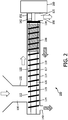
- FIG. 1 schematically depicts a horizontal juice extractor 100 according to an embodiment.
- the horizontal juice extractor 100 may be a masticating juice extractor in at least some embodiments.
- the horizontal juice extractor 100 comprises a main body delimiting a food processing chamber 110 in which a spindle 120 is housed.
- the juice extractor 100 further comprises a drivetrain 160 including a gearbox (not shown) that is coupled to the spindle 120, for instance through a drive shaft 162, and is arranged to rotate the spindle 120 during operation of the horizontal juice extractor 100.
- the food processing chamber 110 comprises a food entry section 112 that is adapted to receive food inserted into the juice extractor 100 through a food inlet 130 and a food compression section 114 in which the food is compressed to extract the juice from the food.
- the food inlet 130 may have any suitable shape, e.g. a funnel shape, and typically includes a wall portion 132 that is proximal to the food compression section 114 for reasons that will be explained in more detail later.
- the food compression section 114 cooperates with the spindle 120 to compress chunks of food that are transported by the spindle 120 from the food entry section 112 to the food compression section 114.
- Such compression is typically realized by gradually reducing the available volume housing the chunks of food as these chains are being transported from the food entry section 112 through the food compression section 114 towards a pulp outlet 150.
- This compression creates a pressure gradient of increasing pressure from the food entry section 112 in the direction of the pulp outlet 150. This pressure gradient forces the juice squeezed out of the chunks of food in the direction of the food entry section 112, where it can exit the juice extractor 100 through juice outlet 140.
- This for instance may be achieved by remaining a small gap 117 between the spindle 120 and the inner wall of the food compression section 114, wherein the gap 117 is dimensioned such that the extracted juice can flow through the gap towards the juice outlet 140, whilst preventing food pulp remaining on the spindle 120 from entering this gap, i.e. the small gap 117 acts as a juice channel in a bottom portion of the food processing chamber 110.
- the juice outlet 140 is located in a bottom portion of the food processing chamber 110 such that the juice outlet 140 is located at or near a distal end of the main body relative to the drivetrain 160.
- This has the advantage that the horizontal juice extractor 100 produces the juice in a particularly accessible location, i.e. at its distal end, which facilitates juice collection and furthermore gives the appearance of the horizontal juice extractor 100 producing juice rather than pulp in case of prior art horizontal juice extractors having a pulp outlet at such a distal end, which is less visually appealing.
- the juice outlet 140 may be arranged such that the juice outlet 140 is further away from the drivetrain 160 than the food inlet 130, i.e.
- the horizontal juice extractor 100 is closer to the distal end of the horizontal juice extractor 100, thereby for instance enabling a large glass or other suitable receptacle for collecting the juice to be placed under the juice outlet 140.
- the horizontal juice extractor 100 preferably comprises a single juice outlet 140 in this location to facilitate easy collection of the expelled juice.
- the pulp outlet 150 is located at a proximal end of the food processing chamber 110 relative to the drivetrain 160, i.e. in a region 115, which may be a terminal region of the food compression section 114 or a region immediately adjacent to the food compression section 114. This has the advantage that the pulp is expelled from the horizontal juice extractor 100 out of immediate view of the user of the horizontal juice extractor 100, thus further improving its appearance.
- the horizontal juice extractor 100 may further comprise a pulp restriction element 154, e.g. a plate or the like, which may be placed in any suitable location, such as in the food compression section 114 such that the helical spindle 120 terminates at the pulp restriction element 154.
- the pulp restriction element 154 typically comprises one or more apertures that cause the pulp transported by the spindle 120 to be forced through the apertures into the region 115 from which the pulp is expelled from the horizontal juice extractor 100 through the pulp outlet 150. This restriction increases the pressure exerted on the pulp, thus forcing the juice to be removed from the pulp.
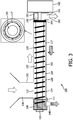
- the removed juice may be collected in one or more juice channels formed by the gaps 117 (shown in the inset of FIG. 3 depicting the cross-section of the horizontal juice extractor as identified by the dashed line), and transported, e.g. gravity-fed and/or pressure gradient-driven, towards the juice outlet 140, as indicated by the hashed block arrows.
- the juice channels may be delimited by the spindle 120 and may extend from the pulp restriction element 154 towards the juice outlet 140.
- the region 115 may comprise a pulp deflection member 152 for deflecting the pulp towards the pulp outlet 150. This will be explained in more detail later.
- the pulp deflection member 152 and the pulp restriction element 154 may form part of a single unit, which for instance reduces the number of components of the horizontal juice extractor 100 and may facilitate the cleaning process of these components.
- pulp restriction element 154 proximal to the drivetrain 160 is that it becomes more straightforward to design the main body of the horizontal juice extractor 100 such that the main body can cope with the forces generated in this pulp restriction area.
- this pulp restriction area is located relatively close to the drivetrain 160, which is typically mounted in relatively rigid housing, a relatively rigid portion of the main body including this pulp restriction area may be directly coupled to the relatively rigid housing of the drivetrain 160, thereby ensuring that the positioning of this part of the main body relative to the pulp restriction element 154 can be well-maintained. It is noted that when such a pulp restriction element 154 is located distal to the drivetrain 160, i.e.
- the spindle 120 comprises a body 122 carrying a helical cutting portion 124 that will be explained in more detail later.
- the helical cutting portion 124 is present on the body 122 at least in the food entry section 112 of the food processing chamber 110.
- the helical cutting portion 124 may extend over the whole of the spindle 120.
- the helical cutting portion 124 may cooperate with a helical food transport portion adjoining the helical cutting portion 124, wherein the helical food transport portion is arranged to transport the food chunks cut by the helical cutting portion 124 from the food entry section 112 towards and through the food compression section 114.
- the spindle 120 will have a constant outer diameter D, which is the combination of the diameter D' of the body 122 and the height H by which the helical member 123 extends from the body 122 as can be seen in the inset showing a magnified view of the portion of the spindle 120 highlighted by the dashed box in FIG. 1 .
- the body 122 may be frustoconical body having a gradually increasing diameter D' in the direction of the pulp outlet 150 such that the height H of the helical member 123 reduces at the same rate and in the same direction in order to ensure that the outer diameter D of the spindle 120 remains constant.
- the inset further depicts the pitch P of the helical member 123, i.e. the distance between neighbouring turns of the helical member 123.
- the pitch P is constant over the full length of the spindle 120, i.e. throughout the food processing chamber 110.
- the pitch P may be variable, e.g. decrease at least in a part of the food compression section 114 in order to aid with the compression of the food chunks inside the food compression section 114 by gradually reducing the available volume for the food chunks transported towards the pulp restriction element 154.
- the horizontal juice extractor 100 further comprises a second and optionally a third helical member on the spindle 120, which additional helical members may start on the spindle 120 downstream from the food inlet 130.
- additional helical members reduce the available volume for the pulp on the spindle 120, thereby compressing the pulp and extracting the juice therefrom.
- the above measures are measures to reduce the volume available to the food chunks by reducing the volume of the compartments defined on the spindle 120.
- the food compression section 114 of the food processing chamber 110 may have a progressively decreasing dimension, e.g. a progressively decreasing diameter, in the food transport direction, such that the gap between the spindle 120 and the inner wall(s) of the food compression section 114 is progressively reduced to reduce the volume available to the food chunks as the food chunks are being transported through the food compression section 114.
- this embodiment may be combined with any of the embodiments in which the volume of the compartments defined on the body 122 of the spindle 120 is progressively reduced in the food transport direction through the food compression section 114.
- the spindle 120 is typically arranged to transport food chunks from the food inlet 130 towards the food compression section 114 as indicated by the clear block arrows in FIG. 1 .
- the helical cutting member 124 of the spindle 120 is shaped such that upon rotation of the spindle 120 by the drivetrain 160, the food chunks are transported towards the drivetrain 160, in contrast with conventional horizontal juice extractors in which the pulp outlet 150 is typically distal to the drivetrain 160, such that the spindle 120 is dimensioned to transport food chunks away from the drivetrain 160.
- the spindle 120 is made of a plastic material. This has the advantage that the spindle 120 can be manufactured cheaply, for instance by molding or casting techniques and is light-weight. This facilitates easy handling of the spindle 120, for instance when it is removed from the juice extractor 100 for cleaning purposes, e.g. for cleaning in a dishwasher.
- the horizontal juice extractor 100 of FIG. 1 further comprises a filter 200 arranged such that the juice extracted from the food pulp in the food compression section 114 must pass the filter 200 in the food compression section 114.
- the filter 200 typically comprises a plurality of apertures (not shown) for passing the juice and capturing pulp residues, such that the juice collected in the gap 117 acting as a juice channel is relatively free of such pulp residues.
- the filter 200 may have a planar or arcuate shape and be located in between the spindle 120 and the gap 117 to collect the juice extracted from the food.
- the filter 200 may be an annular filter enveloping the spindle 120.
- the filter 200 may be secured in the main body of the horizontal juice extractor 100 in any suitable manner.
- the filter 200 may be a modular filter that can be disassembled for easy cleaning, e.g. by rinsing.
- the modular filter may be a telescopic filter that can be extended from an engaged configuration to a disengaged configuration for easy cleaning, e.g. by rinsing.
- the filter 200 may be located in any suitable location of the horizontal juice extractor 100. As shown in FIG. 3 by way of non-limiting example, the filter 200 may alternatively be located over the juice outlet 140 in the food entry section 112. In this embodiment, the juice channel defined by the gap 117 may terminate in the filter 200 such that the juice and pulp transported through the juice channel are collected in the filter 200, and the pulp is separated from the juice by the filter 200 before the juice exits the horizontal juice extractor 100 through juice outlet 140.
- the filter 200 is located in a compartment 111 that may be removed or opened to provide access to the filter 200 for cleaning purposes.
- the filter 200 may be removed in its entirety from the compartment 111.
- part, e.g. a module, of the filter 200 may be secured in the compartment 111, e.g. integrated in the main body of the horizontal juice extractor 100, wherein the other module(s) of the filter 200 may be removed from the compartment 111 for cleaning purposes.
- a knob or dial 113 may be present at an outer surface of the main body, e.g.
- the aperture size may be adjusted to control the pulp content in the juice produced by the horizontal juice extractor 100.
- FIG. 4 schematically depicts a particularly advantageous embodiment of the region 115 in more detail. It has been found by the present inventors that in the horizontal juice extractor 100 according to embodiments of the present invention wherein the pulp is transported towards the drivetrain 160, the geometry of the region 115 has a marked influence on the risk of blocking region 115 or a part of the food compression chamber 114 adjacent to the region 115. For instance, when using a relatively narrow pulp outlet 150 and/or a curved pulp deflector in an upper portion of the region 115 for deflecting pulp towards the pulp outlet 150, it has been found that such geometries when used in the horizontal juice extractor 100 according to embodiments of the present invention may lead to pulp blockages at least for certain food types. In particular, when the width W of the pulp outlet 150 is substantially smaller than the overall width of the region 115, it may be difficult to avoid such blockages.
- such blockages are effectively avoided by ensuring that the width W of the pulp outlet 150 is substantially equal to the overall width of the region 115, thereby creating a free-fall condition for the pulp expelled from the horizontal juice extractor 100.
- the spindle 120 is coupled to the drivetrain 160 by a drive shaft 162 which has a substantially smaller diameter than the spindle 120, which drive shaft 162 extends through the region 115.
- the region 115 may further comprise curved corners 151 in an upper portion of the region 115, which upper portion may be radially extended in an upward direction from the exit of the adjacent region of the food compression chamber 114 by an amount R to further reduce the risk of pulp blockages as this elevated upper portion further reduces the risk of the pulp sticking to the upper portion of the region 115.
- R may be in the range of 10-15 mm and W may be in the range of 30-45 mm to obtain a region 115 that may handle pulp from a wide variety of food products without blocking the region 115.
- the horizontal juice extractor 100 may further comprise a filter 200 for filtering pulp from the extracted juice.
- a filter 200 for filtering pulp from the extracted juice.
- the applicability of these embodiments is not limited to the horizontal juice extractor 100 of the present invention.
- the below embodiments of the filter 200 may be used in any suitable juice extractor.
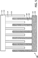
- a first embodiment of a modular filter 200 is schematically depicted in FIG. 5 .
- the modular filter has a first module 210 and a second module 220 that are designed to engage with each other to form an assembled filter 200, whereas in disengaged form the first module 210 and the second module 220 may be easily cleaned, e.g. by rinsing with water.
- the first module 210 comprises a first body 211 from which a plurality of first protrusions 212 extend. Neighbouring first protrusions 212 are separated by respective first gaps 214.
- the second module 220 comprises a second body 221 from which a plurality of second protrusions 222 extend. Neighbouring second protrusions 222 are separated by respective second gaps 224.
- the first body 211 and the second body 221 typically have matching shapes, which for instance may be a planar shape or an arcuate shape.
- the first protrusions 212 and the second protrusions 222 have matching, e.g. identical or complimentary, shapes.
- the first protrusions 212 and the second protrusions 232 may have any suitable shape, such as a shape having a constant width as shown in FIG. 5 .
- the first gaps 214 are dimensioned such that they can receive the second protrusions 222 and the second gaps 224 are dimensioned such that they can receive the first protrusions 212 when the first module 210 is engaged with the second module 220 to assemble the modular filter 200.
- the first module 210 and the second module 220 may be made of any suitable material, e.g. a metal, metal alloy, plastics material and so on, which material may be dishwasher safe such that the respective modules may be cleaned in a dishwasher.
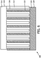
- FIG. 6 schematically depicts the modular filter 200 of FIG. 5 in an assembled form.
- the first protrusions 212 cooperate with the second protrusions 222 to define apertures 230 delimited by the first protrusions 212, the second protrusions 222, the first body 211 and the second body 221.
- the apertures 230 only exist when the first module 210 and the second module 220 of the modular filter 200 are engaged with each other, the modular filter 200 is easy to clean when disassembled due to the fact that any pulp material trapped in the apertures 230 is no longer contained by the apertures 230 when the modular filter 200 is disassembled, such that such pulp material can be easily removed from the respective modules of the modular filter 200 without requiring cleaning utensils, e.g. by rinsing the first module 210 and the second module 220 or by cleaning these modules in a dishwasher.
- the first module 210 may be engaged with the second module 220 in any suitable manner.
- the first protrusions 212 and/or the second protrusions 222 may have a terminal shape for engaging with a matching shape on the second body 221 and/or the first body 211.
- the first module 210 may be engaged with the second module 220 such that the first protrusions 212 and the second protrusions 222 are equidistantly spaced to define a plurality of equally sized apertures 230 wherein each protrusion apart from the terminal protrusions borders a pair of such apertures 230.
- the size of the apertures 230 determines the amount of pulp that can pass through the modular filter 200, thereby controlling the pulp content in the juice that passes through this filter.
- the modular filter 200 is designed such that the size of the apertures 230 may be controlled by the engagement configuration of the first module 210 and the second module 220 in order to control the pulp content in the juice passing through the modular filter 200.
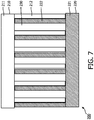
- An example of such an adjustable configuration is schematically shown in FIG. 7 , in which the first module 200 is engaged with the second module 220 such that each first protrusion 210 abuts a second protrusion 220, such that each protrusion is bordered by an opposite protrusion on one side and an aperture 230 on the other side. Consequently, larger sized apertures 230 are formed in this configuration compared to the configuration shown in FIG. 6 .
- the overall aperture area of the modular filter 200 is substantially the same in the respective configurations shown in FIG.
- the flow rate of the juice through the modular filter 200 is not significantly affected by the different configurations, such that the performance of a juice extractor such as the horizontal juice extractor 100 is not affected by the choice of configuration.
- the provision of a modular filter 200 that can be assembled in a plurality of different configurations having different aperture sizes may be achieved in any suitable manner.
- the first body 211 and/or the second body 221 may comprise a plurality of receiving portions for each opposing protrusion, i.e. a plurality of such receiving portions in each gap 214 and/or 224 such that the opposing module can be slotted into the appropriate receiving portion in order to assemble the modular filter in the desired configuration.
- the size of the apertures 230 is controlled by the lateral displacement of the first protrusions 212 and the second protrusions 222 relative to each other.
- FIG. 8 schematically depicts an alternative embodiment of a modular filter 200 in which the size of the apertures 230 may be controlled by the shape of these protrusions.
- the first protrusions 212 and the second protrusions 222 have a trapezoidal or tapered shape wherein each protrusion is at its widest proximal to the body from which these protrusions extend, i.e. the first body 211 and the second body 221 respectively.
- the longitudinal displacement of the first module 210 relative to the second module 220 may be used to control the size of the apertures 230.
- the first module 210 is separated from the second module 220 such that the first subset of the apertures 230 is mainly formed between an end portion of a first protrusion 210, a pair of opposing second protrusions 222 and the second body 221 from which the opposing second protrusions 222 extend and a second subset of the apertures 230 is mainly formed between an end portion of a second protrusion 220, a pair of opposing first protrusions 212 and the first body 211 from which the opposing first protrusions 212 extend.
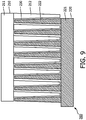
- the size of the apertures 230 may be controlled by controlling the longitudinal displacement of the first module 210 relative to the second module 220 as is shown in FIG. 9 in which the first module 210 is brought into close proximity to the second module 220 such that the apertures 230 are significantly reduced in size.
- the overall aperture area is a function of individual aperture size, such that the flow rate of juice through the modular filter 200 is a function of the chosen configuration of the modular filter 200.
- the first body 211 and the second body 221 may have any suitable shape, such as a planar shape, arcuate shape or annular shape.
- FIG. 10 and 11 schematically depict an aspect of an annular modular filter 200, e.g. a drum filter, having configurable aperture sizes, wherein the size of the apertures 230 may be controlled by rotating one of the modules relative to the other of the modules, thereby altering the positions of the first protrusions 212 relative to the second protrusions 222 as previously explained in more detail with the aid of FIG. 5-7 .
- this has the advantage that the size of the apertures may be configured to control the amount of pulp passing through the modular filter 200 whilst remaining the overall aperture area substantially constant, i.e. independent of the chosen configuration, such that the overall flow characteristics of the modular filter 200 are not significantly affected by the chosen filter configuration.
- FIG. 12 schematically depicts an annular modular filter 200, e.g. a drum filter in a partially assembled state, in which the first slots 215 on the first module 210 for engaging with the end portions 223 of the second protrusions 222 in the assembled state of the annular modular filter 200, as well as the second slots 225 on the second module 220 for engaging with the end portions 213 of the first protrusions 212 in the assembled state of the annular modular filter 200 are shown.
- annular modular filter 200 e.g. a drum filter in a partially assembled state
- FIG. 13 schematically depicts the annular modular filter 200 of FIG. 12 in the assembled form, in which the apertures 230 delimited by opposing protrusions 212, 222 can be identified.
- FIG. 14 schematically depicts a perspective view of a cross-section of an annular modular filter 200 highlighting a particularly advantageous shape of the first protrusions 212 and the second protrusions 222.
- the first protrusions 212 and the second protrusions 222 are tapered in a radial direction such that the apertures 230 radially widen in an outward direction.
- This has the advantage that a relatively narrow aperture 230 is provided at the inner annular surface of the modular filter 200 as defined by the first protrusions 212 and the second protrusions 222, which effectively prevents most of the pulp from passing through the aperture 230, whilst allowing the extracted juice to freely pass through these apertures 230.
- the first module 210 of the annular modular filter 200 having an adjustable aperture size may be mounted in the horizontal juice extractor 100, for instance mounted in the compartment 111 such that the first module 210 may be radially displaced relative to the second module 220 using the knob 113 in order to adjust the size of the apertures 230.
- the knob 113 for instance may be a sprung knob that can be pulled away from the outer wall of the compartment 111 on which the knob is mounted to facilitate the radial displacement of the first module 210 relative to the second module 220.
- the first module 210 may be removably mounted in the compartment 111 to facilitate cleaning of the first module 210 away from the compartment 111.
- the modular filter 200 is designed such that it cannot be accidentally disassembled (or not disassembled at all). This for instance may be achieved by engaging the first module 210 with the second module 220 in a (semi-)permanent fashion, but wherein the first module 210 may be displaced relative to the second module 220, e.g. longitudinally displaced, in order to disrupt the apertures 230 formed in between neighboring first protrusions 212 and second protrusions 222 to facilitate the cleaning of the modular filter 200.
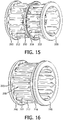
- FIG. 15 schematically depicts the telescopic modular filter 200 in an extended state
- FIG. 16 schematically depicts the telescopic modular filter 200 in an engaged state in which the apertures 230 are delimited by a first protrusion 212 and a second protrusion 222 as previously explained.
- the end portions of the first protrusions 212 are joined by an adjoining ring 216, with the end portions 223 of the second protrusions 222 having a barb shape or the like for engaging with the adjoining ring 216.
- the second protrusions 222 may extend through the adjoining ring 216 with the barbed end portions 223 engaging with the adjoining ring in the extended configuration of the telescopic modular filter 200.
- the adjoining ring 216 acts as a guide when sliding the second module 220 relative to the first module 210 (or vice versa) whilst the barbed end portions 223 prevent the second module 220 from being accidentally separated from the first module 210.
- the second module 220 may be separated from the first module 210 by squeezing the second protrusions 220 inwardly in case the second protrusions 220 are made of a flexible material, e.g. a plastic material, such that the barbed end portions 223 clear the adjoining ring 216 and allow for these and portions to be pulled through the adjoining ring 216 to disassemble the telescopic modular filter 200.
- a flexible material e.g. a plastic material
- the end portions 223 of the second protrusions 222 may also be joined together by a further adjoining ring (not shown), which further adjoining ring for instance may slide over the first protrusions 212 during adjustments of the telescopic modular filter 200.
- the adjoining ring 216 and the further adjoining ring typically abut in the extended configuration of the telescopic modular filter 200, thereby preventing the disassembly of the filter.
Claims (15)
- Horizontaler Entsafter (100), umfassend:einen Hauptkörper, der eine Nahrungsmittelverarbeitungskammer (110) begrenzt, die einen Saftauslass (140), einen Nahrungsmitteleintrittsabschnitt (112), der einen Nahrungsmitteleinlass (130) und einen Nahrungsmittelverdichtungsabschnitt (114) aufweist, der sich von dem Nahrungsmitteleintrittsabschnitt erstreckt und einen Nahrungsmittel-Fruchtfleischauslass (150) aufweist, umfasst;eine Spindel (120), die sich durch die Nahrungsmittelverarbeitungskammer zum Transportieren von Nahrungsmitteln von dem Nahrungsmitteleintrittsabschnitt durch den Nahrungsmittelverdichtungsabschnitt erstreckt, wobei die Spindel einen Körper (122) und ein sich von dem Körper erstreckendes schraubenförmiges Element (123) umfasst; undeinen Antriebsstrang (160), der angepasst ist, um die Spindel zu drehen, wobei der Nahrungsmittelverdichtungsabschnitt (114) sich zwischen dem Nahrungsmitteleintrittsabschnitt (112) und dem Antriebsstrang (160) befindet, dadurch gekennzeichnet, dassder Saftauslass ein einzelner Saftauslass (140) ist;der Nahrungsmitteleintrittsabschnitt (112) den Saftauslass (140) an oder nahe einem distalen Ende des Hauptkörpers relativ zu dem Antriebsstrang umfasst;und dass der Saftauslass (140) relativ zu dem Nahrungsmitteleinlass (130) vertikal verschoben ist.
- Horizontaler Entsafter (100) nach Anspruch 1, weiter umfassend:ein Fruchtfleischbeschränkungselement (154) in dem Nahrungsmittelverdichtungsabschnitt (114), wobei die Spindel (120) an dem Fruchtfleischbeschränkungselement endet, wobei das Fruchtfleischbeschränkungselement eine Vielzahl von Öffnungen umfasst, die bewirken, dass von der Spindel transportierter Nahrungsmittelfruchtfleisch in den Nahrungsmittel-Fruchtfleischauslass (150) ausgestoßen wird; undeine Vielzahl von Saftkanälen, die durch die Spindel begrenzt sind und sich von dem Fruchtfleischbeschränkungselement zu dem Saftauslass (140) erstrecken.
- Horizontaler Entsafter (100) nach Anspruch 1 oder 2, wobei die Spindel (120) mit dem Antriebsstrang (160) durch eine Antriebswelle (162) gekoppelt ist, die mit dem Körper (122) in Eingriff steht, wobei sich die Antriebswelle durch einen Bereich (115) des Nahrungsmittelverdichtungsabschnitts (114) proximal an dem Antriebsstrang erstreckt, wobei sich der Fruchtfleischauslass (150) in einem unteren Abschnitt des Bereichs befindet.
- Horizontaler Entsafter (100) nach Anspruch 3, wobei sich der Fruchtfleischauslass über eine volle Breite (W) des Bereichs (115) erstreckt.
- Horizontaler Entsafter (100) nach Anspruch 3 oder 4, wobei der Bereich einen oberen Abschnitt (152) aufweist, der durch gekrümmte Ecken begrenzt ist.
- Horizontaler Entsafter (100) nach einem der Ansprüche 1-5, wobei die Spindel (120) einen abnehmenden Außendurchmesser in der Richtung von dem Nahrungsmitteleintrittsabschnitt (112) zu dem Fruchtfleischauslass (150) aufweist.
- Horizontaler Entsafter (100) nach einem der Ansprüche 1-6, wobei die Steigung (P) und/oder die Höhe (H) des schraubenförmigen Elements (123) in der Richtung von dem Nahrungsmitteleintrittsabschnitt (112) zu dem Fruchtfleischauslass (150) zumindest innerhalb des Nahrungsmittelverdichtungsabschnitts (114) abnimmt.
- Horizontaler Entsafter (100) nach einem der Ansprüche 1-7, wobei die Innenabmessungen des Nahrungsmittelverdichtungsabschnitts (114) in einer Richtung von dem Nahrungsmitteleintrittsabschnitt (112) zu dem Fruchtfleischauslass (150) abnehmen.
- Horizontaler Entsafter (100) nach einem der Ansprüche 1-8, weiter umfassend einen Filter (200) zum Filtern des extrahierten Safts.
- Horizontaler Entsafter (100) nach Anspruch 9, wobei der Filter (200) ein Teleskopfilter ist, der ein erstes Modul (210) beinhaltet, das eine Vielzahl von ersten Vorsprüngen (212) aufweist, die mit einem zweiten Modul (220) in Eingriff stehen, das eine Vielzahl von zweiten Vorsprüngen (222) aufweist, sodass der Teleskopfilter axial von einer Eingriffsposition, in der die ersten Vorsprünge und die zweiten Vorsprünge zusammenwirken, gestreckt werden kann, um eine Vielzahl von Öffnungen (230) in einer gestreckten Position zum Reinigen des ersten Moduls und des zweiten Moduls zu definieren.
- Horizontaler Entsafter (100) nach Anspruch 9, wobei der Filter (200) ein modularer Filter ist, das ein erstes Modul (210) und ein zweites Modul (220) beinhaltet, wobei der Filter weiter eine Vielzahl von Öffnungen (230) umfasst, die jeweils durch das erste Modul und das zweite Modul begrenzt sind.
- Horizontaler Entsafter (100) nach Anspruch 11, wobei:das erste Modul (210) einen ersten Körper (211) umfasst, von dem sich eine Vielzahl von ersten Vorsprüngen (212) erstreckt; unddas zweite Modul (220) einen zweiten Körper (221) umfasst, von dem sich eine Vielzahl von zweiten Vorsprüngen (222) erstrecken, wobei die ersten Vorsprünge und die zweiten Vorsprünge geformt sind, um so zusammenwirken, dass die Öffnungen (230) zumindest teilweise durch die ersten Vorsprünge und die zweiten Vorsprünge begrenzt sind.
- Horizontaler Entsafter (100) nach Anspruch 12, wobei der Filter (200) eine ebene oder bogenförmige Form aufweist.
- Horizontaler Entsafter (100) nach Anspruch 12, wobei der Nahrungsmitteleinlass (130) näher an dem Nahrungsmittelverdichtungsabschnitt (114) ist als der Saftauslass (140), und der Filter eine ringförmige Form aufweist, um einen Teil der Spindel über dem Saftauslass zu umgeben.
- Horizontaler Entsafter (100) nach einem der Ansprüche 11 bis 14, wobei die Positionierung des ersten Moduls (210) relativ zu dem zweiten Modul (220) einstellbar ist, wobei die Einstellung die Größe der Öffnungen (230) einstellt.
Priority Applications (1)
| Application Number | Priority Date | Filing Date | Title |
|---|---|---|---|
| PL15771116T PL3206541T3 (pl) | 2014-10-15 | 2015-09-30 | Pozioma wyciskarka do soków |
Applications Claiming Priority (2)
| Application Number | Priority Date | Filing Date | Title |
|---|---|---|---|
| EP14189084 | 2014-10-15 | ||
| PCT/EP2015/072503 WO2016058829A1 (en) | 2014-10-15 | 2015-09-30 | Horizontal juice extractor |
Publications (2)
| Publication Number | Publication Date |
|---|---|
| EP3206541A1 EP3206541A1 (de) | 2017-08-23 |
| EP3206541B1 true EP3206541B1 (de) | 2018-12-12 |
Family
ID=51703059
Family Applications (1)
| Application Number | Title | Priority Date | Filing Date |
|---|---|---|---|
| EP15771116.9A Active EP3206541B1 (de) | 2014-10-15 | 2015-09-30 | Horizontaler entsafter |
Country Status (8)
| Country | Link |
|---|---|
| US (1) | US10646063B2 (de) |
| EP (1) | EP3206541B1 (de) |
| JP (1) | JP6422571B2 (de) |
| CN (2) | CN205234237U (de) |
| MX (1) | MX2017004625A (de) |
| PL (1) | PL3206541T3 (de) |
| RU (1) | RU2711270C2 (de) |
| WO (1) | WO2016058829A1 (de) |
Families Citing this family (8)
| Publication number | Priority date | Publication date | Assignee | Title |
|---|---|---|---|---|
| US10654235B2 (en) * | 2012-06-13 | 2020-05-19 | Iogen Energy Corporation | Method for removing liquid from a slurry |
| US10646063B2 (en) | 2014-10-15 | 2020-05-12 | Koninklijke Philips N.V. | Horizontal juice extractor |
| US10118358B2 (en) * | 2014-12-22 | 2018-11-06 | Us Farm Systems, Inc. | Screw press for separation of liquid from bulk materials |
| WO2018073195A1 (en) | 2016-10-17 | 2018-04-26 | Koninklijke Philips N.V. | Juice extractor |
| CN107280020A (zh) * | 2017-08-10 | 2017-10-24 | 安徽独秀山蓝莓科技开发有限公司 | 一种蓝莓挤汁装置 |
| CN109730518B (zh) * | 2019-02-26 | 2021-06-25 | 许昌学院 | 一种食品加工机渣汁分离装置 |
| TWM615621U (zh) * | 2021-04-23 | 2021-08-11 | 林國義 | 可更換加工器的多用途食品加工機 |
| CN113662203B (zh) * | 2021-09-03 | 2023-09-15 | 中禾宝桑生物科技有限公司 | 一种果蔬打浆机 |
Family Cites Families (15)
| Publication number | Priority date | Publication date | Assignee | Title |
|---|---|---|---|---|
| GB1000773A (en) * | 1963-03-04 | 1965-08-11 | Coproducts Corporation | Extracting Fluids from Solids by Means of a Press and Cage Assembly |
| GB1506455A (en) * | 1975-03-13 | 1978-04-05 | Stork Amsterdam | Device for the extraction of liquids from fibrous substances eg oil-containing fruits |
| US4273035A (en) * | 1978-08-29 | 1981-06-16 | Cusi Dante S | Method and apparatus for stabilizing operation of a press |
| KR960003079Y1 (ko) | 1993-12-24 | 1996-04-16 | 이몽용 | 착즙기 |
| US5592873A (en) | 1995-12-01 | 1997-01-14 | Angel Life Co., Ltd. | Juice extractor |
| US5906154A (en) * | 1997-11-25 | 1999-05-25 | Dong-A Engineering Co., Ltd. | Juice extractor |
| CN2458957Y (zh) * | 2001-01-10 | 2001-11-14 | 叶仲伦 | 手动渣汁分离型榨汁机 |
| KR200274699Y1 (ko) * | 2002-02-15 | 2002-05-04 | 김영기 | 착즙 분쇄기 |
| US8474374B2 (en) | 2007-09-06 | 2013-07-02 | Russell T. Trovinger | Juicer with alternate cutters |
| CN101697857B (zh) * | 2009-10-29 | 2012-09-05 | 九阳股份有限公司 | 易清洗挤压式榨汁机 |
| KR101282313B1 (ko) * | 2011-06-14 | 2013-07-04 | 김영기 | 착즙기 |
| US20130074707A1 (en) | 2011-09-27 | 2013-03-28 | Greenfield World Trade, Inc. | Horizontal juicer with compression strainer device |
| KR101319763B1 (ko) * | 2011-11-09 | 2013-10-17 | 염무연 | 곡물 착유기 |
| CN203555515U (zh) * | 2013-11-22 | 2014-04-23 | 宁波凯普电子有限公司 | 水平出口可调节榨汁机 |
| US10646063B2 (en) | 2014-10-15 | 2020-05-12 | Koninklijke Philips N.V. | Horizontal juice extractor |
-
2015
- 2015-09-30 US US15/518,334 patent/US10646063B2/en active Active
- 2015-09-30 RU RU2017116508A patent/RU2711270C2/ru active
- 2015-09-30 PL PL15771116T patent/PL3206541T3/pl unknown
- 2015-09-30 JP JP2017513534A patent/JP6422571B2/ja not_active Expired - Fee Related
- 2015-09-30 EP EP15771116.9A patent/EP3206541B1/de active Active
- 2015-09-30 WO PCT/EP2015/072503 patent/WO2016058829A1/en active Application Filing
- 2015-09-30 MX MX2017004625A patent/MX2017004625A/es unknown
- 2015-10-14 CN CN201520794869.8U patent/CN205234237U/zh active Active
- 2015-10-14 CN CN201510663224.5A patent/CN105520498B/zh active Active
Non-Patent Citations (1)
| Title |
|---|
| None * |
Also Published As
| Publication number | Publication date |
|---|---|
| PL3206541T3 (pl) | 2019-05-31 |
| US10646063B2 (en) | 2020-05-12 |
| RU2711270C2 (ru) | 2020-01-16 |
| JP2017534319A (ja) | 2017-11-24 |
| JP6422571B2 (ja) | 2018-11-14 |
| CN105520498A (zh) | 2016-04-27 |
| US20170303723A1 (en) | 2017-10-26 |
| WO2016058829A1 (en) | 2016-04-21 |
| BR112017007454A2 (pt) | 2018-01-16 |
| RU2017116508A3 (de) | 2019-05-08 |
| CN105520498B (zh) | 2019-12-06 |
| RU2017116508A (ru) | 2018-11-15 |
| MX2017004625A (es) | 2017-06-30 |
| CN205234237U (zh) | 2016-05-18 |
| EP3206541A1 (de) | 2017-08-23 |
Similar Documents
| Publication | Publication Date | Title |
|---|---|---|
| EP3206541B1 (de) | Horizontaler entsafter | |
| EP3197325B1 (de) | Modularer sieb und entsafter | |
| EP2731472B1 (de) | Separator mit mahlwerk zum abtrennen von obst- oder gemüsesaft vom fruchtfleisch | |
| EP2545817A1 (de) | Zentrifugaltrenner zum Entfernen von Fruchtfleisch aus Obst- oder Gemüsesaft | |
| TW201417751A (zh) | 用於榨汁機的榨汁模組 | |
| US20200367696A1 (en) | Juicing devices with a removable grinder assembly | |
| EP3016554B1 (de) | Saftextraktor | |
| CN104783635B (zh) | 具有空心取汁螺杆的取汁装置 | |
| CN106913188B (zh) | 用于通过挤压制备食物汁液的电器 | |
| DE102009049208B4 (de) | Zentrifuge mit hohem Durchsatz | |
| KR101432635B1 (ko) | 사탕수수용 착즙기 | |
| US20150201667A1 (en) | Masticating separator for separating fruit or vegetable juice from fruit or vegetable pulp | |
| DE202015104963U1 (de) | Lebensmittel-Verarbeitungsvorrichtung | |
| CN106308443B (zh) | 料理机 | |
| WO2018001381A1 (zh) | 一种用于榨汁机或榨油机的滤网结构及具有该滤网结构的榨汁机或榨油机 | |
| CN209899056U (zh) | 滤网组件及具有其的原汁机 | |
| CN208694404U (zh) | 一种花椒油制作用过滤装置 | |
| CN208447194U (zh) | 榨汁机榨碗结构 | |
| CN111317341B (zh) | 榨汁网、食物处理杯组件及食物处理机 | |
| EP3468425B1 (de) | Lebensmittelverarbeitungsvorrichtung und deren spindel | |
| BR112017007454B1 (pt) | Extrator de suco horizontal | |
| CN106333599B (zh) | 网孔筒组件及具有该网孔筒组件的料理机 | |
| CN106308574B (zh) | 料理机 | |
| CN106798486A (zh) | 食物处理装置 | |
| WO2018209610A1 (zh) | 无滤网易清洗的慢速榨汁装置 |
Legal Events
| Date | Code | Title | Description |
|---|---|---|---|
| STAA | Information on the status of an ep patent application or granted ep patent |
Free format text: STATUS: THE INTERNATIONAL PUBLICATION HAS BEEN MADE |
|
| PUAI | Public reference made under article 153(3) epc to a published international application that has entered the european phase |
Free format text: ORIGINAL CODE: 0009012 |
|
| STAA | Information on the status of an ep patent application or granted ep patent |
Free format text: STATUS: REQUEST FOR EXAMINATION WAS MADE |
|
| 17P | Request for examination filed |
Effective date: 20170515 |
|
| AK | Designated contracting states |
Kind code of ref document: A1 Designated state(s): AL AT BE BG CH CY CZ DE DK EE ES FI FR GB GR HR HU IE IS IT LI LT LU LV MC MK MT NL NO PL PT RO RS SE SI SK SM TR |
|
| AX | Request for extension of the european patent |
Extension state: BA ME |
|
| DAV | Request for validation of the european patent (deleted) | ||
| DAX | Request for extension of the european patent (deleted) | ||
| GRAP | Despatch of communication of intention to grant a patent |
Free format text: ORIGINAL CODE: EPIDOSNIGR1 |
|
| STAA | Information on the status of an ep patent application or granted ep patent |
Free format text: STATUS: GRANT OF PATENT IS INTENDED |
|
| INTG | Intention to grant announced |
Effective date: 20180628 |
|
| GRAS | Grant fee paid |
Free format text: ORIGINAL CODE: EPIDOSNIGR3 |
|
| GRAA | (expected) grant |
Free format text: ORIGINAL CODE: 0009210 |
|
| STAA | Information on the status of an ep patent application or granted ep patent |
Free format text: STATUS: THE PATENT HAS BEEN GRANTED |
|
| AK | Designated contracting states |
Kind code of ref document: B1 Designated state(s): AL AT BE BG CH CY CZ DE DK EE ES FI FR GB GR HR HU IE IS IT LI LT LU LV MC MK MT NL NO PL PT RO RS SE SI SK SM TR |
|
| REG | Reference to a national code |
Ref country code: GB Ref legal event code: FG4D |
|
| REG | Reference to a national code |
Ref country code: CH Ref legal event code: EP |
|
| REG | Reference to a national code |
Ref country code: AT Ref legal event code: REF Ref document number: 1074884 Country of ref document: AT Kind code of ref document: T Effective date: 20181215 |
|
| REG | Reference to a national code |
Ref country code: DE Ref legal event code: R096 Ref document number: 602015021444 Country of ref document: DE |
|
| REG | Reference to a national code |
Ref country code: IE Ref legal event code: FG4D |
|
| REG | Reference to a national code |
Ref country code: NL Ref legal event code: MP Effective date: 20181212 |
|
| REG | Reference to a national code |
Ref country code: LT Ref legal event code: MG4D |
|
| PG25 | Lapsed in a contracting state [announced via postgrant information from national office to epo] |
Ref country code: BG Free format text: LAPSE BECAUSE OF FAILURE TO SUBMIT A TRANSLATION OF THE DESCRIPTION OR TO PAY THE FEE WITHIN THE PRESCRIBED TIME-LIMIT Effective date: 20190312 Ref country code: LT Free format text: LAPSE BECAUSE OF FAILURE TO SUBMIT A TRANSLATION OF THE DESCRIPTION OR TO PAY THE FEE WITHIN THE PRESCRIBED TIME-LIMIT Effective date: 20181212 Ref country code: NO Free format text: LAPSE BECAUSE OF FAILURE TO SUBMIT A TRANSLATION OF THE DESCRIPTION OR TO PAY THE FEE WITHIN THE PRESCRIBED TIME-LIMIT Effective date: 20190312 Ref country code: FI Free format text: LAPSE BECAUSE OF FAILURE TO SUBMIT A TRANSLATION OF THE DESCRIPTION OR TO PAY THE FEE WITHIN THE PRESCRIBED TIME-LIMIT Effective date: 20181212 Ref country code: LV Free format text: LAPSE BECAUSE OF FAILURE TO SUBMIT A TRANSLATION OF THE DESCRIPTION OR TO PAY THE FEE WITHIN THE PRESCRIBED TIME-LIMIT Effective date: 20181212 Ref country code: HR Free format text: LAPSE BECAUSE OF FAILURE TO SUBMIT A TRANSLATION OF THE DESCRIPTION OR TO PAY THE FEE WITHIN THE PRESCRIBED TIME-LIMIT Effective date: 20181212 Ref country code: ES Free format text: LAPSE BECAUSE OF FAILURE TO SUBMIT A TRANSLATION OF THE DESCRIPTION OR TO PAY THE FEE WITHIN THE PRESCRIBED TIME-LIMIT Effective date: 20181212 |
|
| REG | Reference to a national code |
Ref country code: AT Ref legal event code: MK05 Ref document number: 1074884 Country of ref document: AT Kind code of ref document: T Effective date: 20181212 |
|
| PG25 | Lapsed in a contracting state [announced via postgrant information from national office to epo] |
Ref country code: GR Free format text: LAPSE BECAUSE OF FAILURE TO SUBMIT A TRANSLATION OF THE DESCRIPTION OR TO PAY THE FEE WITHIN THE PRESCRIBED TIME-LIMIT Effective date: 20190313 Ref country code: SE Free format text: LAPSE BECAUSE OF FAILURE TO SUBMIT A TRANSLATION OF THE DESCRIPTION OR TO PAY THE FEE WITHIN THE PRESCRIBED TIME-LIMIT Effective date: 20181212 Ref country code: RS Free format text: LAPSE BECAUSE OF FAILURE TO SUBMIT A TRANSLATION OF THE DESCRIPTION OR TO PAY THE FEE WITHIN THE PRESCRIBED TIME-LIMIT Effective date: 20181212 Ref country code: AL Free format text: LAPSE BECAUSE OF FAILURE TO SUBMIT A TRANSLATION OF THE DESCRIPTION OR TO PAY THE FEE WITHIN THE PRESCRIBED TIME-LIMIT Effective date: 20181212 |
|
| PG25 | Lapsed in a contracting state [announced via postgrant information from national office to epo] |
Ref country code: NL Free format text: LAPSE BECAUSE OF FAILURE TO SUBMIT A TRANSLATION OF THE DESCRIPTION OR TO PAY THE FEE WITHIN THE PRESCRIBED TIME-LIMIT Effective date: 20181212 |
|
| PG25 | Lapsed in a contracting state [announced via postgrant information from national office to epo] |
Ref country code: PT Free format text: LAPSE BECAUSE OF FAILURE TO SUBMIT A TRANSLATION OF THE DESCRIPTION OR TO PAY THE FEE WITHIN THE PRESCRIBED TIME-LIMIT Effective date: 20190412 Ref country code: CZ Free format text: LAPSE BECAUSE OF FAILURE TO SUBMIT A TRANSLATION OF THE DESCRIPTION OR TO PAY THE FEE WITHIN THE PRESCRIBED TIME-LIMIT Effective date: 20181212 |
|
| PG25 | Lapsed in a contracting state [announced via postgrant information from national office to epo] |
Ref country code: IS Free format text: LAPSE BECAUSE OF FAILURE TO SUBMIT A TRANSLATION OF THE DESCRIPTION OR TO PAY THE FEE WITHIN THE PRESCRIBED TIME-LIMIT Effective date: 20190412 Ref country code: SK Free format text: LAPSE BECAUSE OF FAILURE TO SUBMIT A TRANSLATION OF THE DESCRIPTION OR TO PAY THE FEE WITHIN THE PRESCRIBED TIME-LIMIT Effective date: 20181212 Ref country code: RO Free format text: LAPSE BECAUSE OF FAILURE TO SUBMIT A TRANSLATION OF THE DESCRIPTION OR TO PAY THE FEE WITHIN THE PRESCRIBED TIME-LIMIT Effective date: 20181212 Ref country code: SM Free format text: LAPSE BECAUSE OF FAILURE TO SUBMIT A TRANSLATION OF THE DESCRIPTION OR TO PAY THE FEE WITHIN THE PRESCRIBED TIME-LIMIT Effective date: 20181212 Ref country code: EE Free format text: LAPSE BECAUSE OF FAILURE TO SUBMIT A TRANSLATION OF THE DESCRIPTION OR TO PAY THE FEE WITHIN THE PRESCRIBED TIME-LIMIT Effective date: 20181212 |
|
| REG | Reference to a national code |
Ref country code: DE Ref legal event code: R097 Ref document number: 602015021444 Country of ref document: DE |
|
| PLBE | No opposition filed within time limit |
Free format text: ORIGINAL CODE: 0009261 |
|
| STAA | Information on the status of an ep patent application or granted ep patent |
Free format text: STATUS: NO OPPOSITION FILED WITHIN TIME LIMIT |
|
| PG25 | Lapsed in a contracting state [announced via postgrant information from national office to epo] |
Ref country code: DK Free format text: LAPSE BECAUSE OF FAILURE TO SUBMIT A TRANSLATION OF THE DESCRIPTION OR TO PAY THE FEE WITHIN THE PRESCRIBED TIME-LIMIT Effective date: 20181212 Ref country code: AT Free format text: LAPSE BECAUSE OF FAILURE TO SUBMIT A TRANSLATION OF THE DESCRIPTION OR TO PAY THE FEE WITHIN THE PRESCRIBED TIME-LIMIT Effective date: 20181212 Ref country code: SI Free format text: LAPSE BECAUSE OF FAILURE TO SUBMIT A TRANSLATION OF THE DESCRIPTION OR TO PAY THE FEE WITHIN THE PRESCRIBED TIME-LIMIT Effective date: 20181212 |
|
| 26N | No opposition filed |
Effective date: 20190913 |
|
| PG25 | Lapsed in a contracting state [announced via postgrant information from national office to epo] |
Ref country code: TR Free format text: LAPSE BECAUSE OF FAILURE TO SUBMIT A TRANSLATION OF THE DESCRIPTION OR TO PAY THE FEE WITHIN THE PRESCRIBED TIME-LIMIT Effective date: 20181212 |
|
| PG25 | Lapsed in a contracting state [announced via postgrant information from national office to epo] |
Ref country code: MC Free format text: LAPSE BECAUSE OF FAILURE TO SUBMIT A TRANSLATION OF THE DESCRIPTION OR TO PAY THE FEE WITHIN THE PRESCRIBED TIME-LIMIT Effective date: 20181212 |
|
| REG | Reference to a national code |
Ref country code: CH Ref legal event code: PL |
|
| PG25 | Lapsed in a contracting state [announced via postgrant information from national office to epo] |
Ref country code: CH Free format text: LAPSE BECAUSE OF NON-PAYMENT OF DUE FEES Effective date: 20190930 Ref country code: LI Free format text: LAPSE BECAUSE OF NON-PAYMENT OF DUE FEES Effective date: 20190930 Ref country code: LU Free format text: LAPSE BECAUSE OF NON-PAYMENT OF DUE FEES Effective date: 20190930 Ref country code: IE Free format text: LAPSE BECAUSE OF NON-PAYMENT OF DUE FEES Effective date: 20190930 |
|
| REG | Reference to a national code |
Ref country code: BE Ref legal event code: MM Effective date: 20190930 |
|
| PG25 | Lapsed in a contracting state [announced via postgrant information from national office to epo] |
Ref country code: BE Free format text: LAPSE BECAUSE OF NON-PAYMENT OF DUE FEES Effective date: 20190930 |
|
| GBPC | Gb: european patent ceased through non-payment of renewal fee |
Effective date: 20190930 |
|
| PG25 | Lapsed in a contracting state [announced via postgrant information from national office to epo] |
Ref country code: GB Free format text: LAPSE BECAUSE OF NON-PAYMENT OF DUE FEES Effective date: 20190930 |
|
| PG25 | Lapsed in a contracting state [announced via postgrant information from national office to epo] |
Ref country code: CY Free format text: LAPSE BECAUSE OF FAILURE TO SUBMIT A TRANSLATION OF THE DESCRIPTION OR TO PAY THE FEE WITHIN THE PRESCRIBED TIME-LIMIT Effective date: 20181212 |
|
| PG25 | Lapsed in a contracting state [announced via postgrant information from national office to epo] |
Ref country code: HU Free format text: LAPSE BECAUSE OF FAILURE TO SUBMIT A TRANSLATION OF THE DESCRIPTION OR TO PAY THE FEE WITHIN THE PRESCRIBED TIME-LIMIT; INVALID AB INITIO Effective date: 20150930 Ref country code: MT Free format text: LAPSE BECAUSE OF FAILURE TO SUBMIT A TRANSLATION OF THE DESCRIPTION OR TO PAY THE FEE WITHIN THE PRESCRIBED TIME-LIMIT Effective date: 20181212 |
|
| PG25 | Lapsed in a contracting state [announced via postgrant information from national office to epo] |
Ref country code: MK Free format text: LAPSE BECAUSE OF FAILURE TO SUBMIT A TRANSLATION OF THE DESCRIPTION OR TO PAY THE FEE WITHIN THE PRESCRIBED TIME-LIMIT Effective date: 20181212 |
|
| P01 | Opt-out of the competence of the unified patent court (upc) registered |
Effective date: 20230530 |
|
| PGFP | Annual fee paid to national office [announced via postgrant information from national office to epo] |
Ref country code: IT Payment date: 20230920 Year of fee payment: 9 |
|
| PGFP | Annual fee paid to national office [announced via postgrant information from national office to epo] |
Ref country code: PL Payment date: 20230920 Year of fee payment: 9 Ref country code: FR Payment date: 20230926 Year of fee payment: 9 Ref country code: DE Payment date: 20230928 Year of fee payment: 9 |
|
| REG | Reference to a national code |
Ref country code: DE Ref legal event code: R081 Ref document number: 602015021444 Country of ref document: DE Owner name: VERSUNI HOLDING B.V., NL Free format text: FORMER OWNER: KONINKLIJKE PHILIPS N.V., EINDHOVEN, NL |