EP3206296A1 - Electric power supply system, control device, vehicle, and engine/generator unit for vehicle drive - Google Patents
Electric power supply system, control device, vehicle, and engine/generator unit for vehicle drive Download PDFInfo
- Publication number
- EP3206296A1 EP3206296A1 EP15864204.1A EP15864204A EP3206296A1 EP 3206296 A1 EP3206296 A1 EP 3206296A1 EP 15864204 A EP15864204 A EP 15864204A EP 3206296 A1 EP3206296 A1 EP 3206296A1
- Authority
- EP
- European Patent Office
- Prior art keywords
- current
- winding
- stator core
- adjustment unit
- engine
- Prior art date
- Legal status (The legal status is an assumption and is not a legal conclusion. Google has not performed a legal analysis and makes no representation as to the accuracy of the status listed.)
- Granted
Links
Images



Classifications
-
- B—PERFORMING OPERATIONS; TRANSPORTING
- B60—VEHICLES IN GENERAL
- B60K—ARRANGEMENT OR MOUNTING OF PROPULSION UNITS OR OF TRANSMISSIONS IN VEHICLES; ARRANGEMENT OR MOUNTING OF PLURAL DIVERSE PRIME-MOVERS IN VEHICLES; AUXILIARY DRIVES FOR VEHICLES; INSTRUMENTATION OR DASHBOARDS FOR VEHICLES; ARRANGEMENTS IN CONNECTION WITH COOLING, AIR INTAKE, GAS EXHAUST OR FUEL SUPPLY OF PROPULSION UNITS IN VEHICLES
- B60K1/00—Arrangement or mounting of electrical propulsion units
- B60K1/02—Arrangement or mounting of electrical propulsion units comprising more than one electric motor
-
- B—PERFORMING OPERATIONS; TRANSPORTING
- B60—VEHICLES IN GENERAL
- B60K—ARRANGEMENT OR MOUNTING OF PROPULSION UNITS OR OF TRANSMISSIONS IN VEHICLES; ARRANGEMENT OR MOUNTING OF PLURAL DIVERSE PRIME-MOVERS IN VEHICLES; AUXILIARY DRIVES FOR VEHICLES; INSTRUMENTATION OR DASHBOARDS FOR VEHICLES; ARRANGEMENTS IN CONNECTION WITH COOLING, AIR INTAKE, GAS EXHAUST OR FUEL SUPPLY OF PROPULSION UNITS IN VEHICLES
- B60K1/00—Arrangement or mounting of electrical propulsion units
-
- B—PERFORMING OPERATIONS; TRANSPORTING
- B60—VEHICLES IN GENERAL
- B60K—ARRANGEMENT OR MOUNTING OF PROPULSION UNITS OR OF TRANSMISSIONS IN VEHICLES; ARRANGEMENT OR MOUNTING OF PLURAL DIVERSE PRIME-MOVERS IN VEHICLES; AUXILIARY DRIVES FOR VEHICLES; INSTRUMENTATION OR DASHBOARDS FOR VEHICLES; ARRANGEMENTS IN CONNECTION WITH COOLING, AIR INTAKE, GAS EXHAUST OR FUEL SUPPLY OF PROPULSION UNITS IN VEHICLES
- B60K6/00—Arrangement or mounting of plural diverse prime-movers for mutual or common propulsion, e.g. hybrid propulsion systems comprising electric motors and internal combustion engines
- B60K6/20—Arrangement or mounting of plural diverse prime-movers for mutual or common propulsion, e.g. hybrid propulsion systems comprising electric motors and internal combustion engines the prime-movers consisting of electric motors and internal combustion engines, e.g. HEVs
-
- B—PERFORMING OPERATIONS; TRANSPORTING
- B60—VEHICLES IN GENERAL
- B60K—ARRANGEMENT OR MOUNTING OF PROPULSION UNITS OR OF TRANSMISSIONS IN VEHICLES; ARRANGEMENT OR MOUNTING OF PLURAL DIVERSE PRIME-MOVERS IN VEHICLES; AUXILIARY DRIVES FOR VEHICLES; INSTRUMENTATION OR DASHBOARDS FOR VEHICLES; ARRANGEMENTS IN CONNECTION WITH COOLING, AIR INTAKE, GAS EXHAUST OR FUEL SUPPLY OF PROPULSION UNITS IN VEHICLES
- B60K6/00—Arrangement or mounting of plural diverse prime-movers for mutual or common propulsion, e.g. hybrid propulsion systems comprising electric motors and internal combustion engines
- B60K6/20—Arrangement or mounting of plural diverse prime-movers for mutual or common propulsion, e.g. hybrid propulsion systems comprising electric motors and internal combustion engines the prime-movers consisting of electric motors and internal combustion engines, e.g. HEVs
- B60K6/22—Arrangement or mounting of plural diverse prime-movers for mutual or common propulsion, e.g. hybrid propulsion systems comprising electric motors and internal combustion engines the prime-movers consisting of electric motors and internal combustion engines, e.g. HEVs characterised by apparatus, components or means specially adapted for HEVs
- B60K6/26—Arrangement or mounting of plural diverse prime-movers for mutual or common propulsion, e.g. hybrid propulsion systems comprising electric motors and internal combustion engines the prime-movers consisting of electric motors and internal combustion engines, e.g. HEVs characterised by apparatus, components or means specially adapted for HEVs characterised by the motors or the generators
-
- B—PERFORMING OPERATIONS; TRANSPORTING
- B60—VEHICLES IN GENERAL
- B60L—PROPULSION OF ELECTRICALLY-PROPELLED VEHICLES; SUPPLYING ELECTRIC POWER FOR AUXILIARY EQUIPMENT OF ELECTRICALLY-PROPELLED VEHICLES; ELECTRODYNAMIC BRAKE SYSTEMS FOR VEHICLES IN GENERAL; MAGNETIC SUSPENSION OR LEVITATION FOR VEHICLES; MONITORING OPERATING VARIABLES OF ELECTRICALLY-PROPELLED VEHICLES; ELECTRIC SAFETY DEVICES FOR ELECTRICALLY-PROPELLED VEHICLES
- B60L50/00—Electric propulsion with power supplied within the vehicle
- B60L50/10—Electric propulsion with power supplied within the vehicle using propulsion power supplied by engine-driven generators, e.g. generators driven by combustion engines
-
- B—PERFORMING OPERATIONS; TRANSPORTING
- B60—VEHICLES IN GENERAL
- B60L—PROPULSION OF ELECTRICALLY-PROPELLED VEHICLES; SUPPLYING ELECTRIC POWER FOR AUXILIARY EQUIPMENT OF ELECTRICALLY-PROPELLED VEHICLES; ELECTRODYNAMIC BRAKE SYSTEMS FOR VEHICLES IN GENERAL; MAGNETIC SUSPENSION OR LEVITATION FOR VEHICLES; MONITORING OPERATING VARIABLES OF ELECTRICALLY-PROPELLED VEHICLES; ELECTRIC SAFETY DEVICES FOR ELECTRICALLY-PROPELLED VEHICLES
- B60L50/00—Electric propulsion with power supplied within the vehicle
- B60L50/10—Electric propulsion with power supplied within the vehicle using propulsion power supplied by engine-driven generators, e.g. generators driven by combustion engines
- B60L50/13—Electric propulsion with power supplied within the vehicle using propulsion power supplied by engine-driven generators, e.g. generators driven by combustion engines using AC generators and AC motors
-
- B—PERFORMING OPERATIONS; TRANSPORTING
- B60—VEHICLES IN GENERAL
- B60L—PROPULSION OF ELECTRICALLY-PROPELLED VEHICLES; SUPPLYING ELECTRIC POWER FOR AUXILIARY EQUIPMENT OF ELECTRICALLY-PROPELLED VEHICLES; ELECTRODYNAMIC BRAKE SYSTEMS FOR VEHICLES IN GENERAL; MAGNETIC SUSPENSION OR LEVITATION FOR VEHICLES; MONITORING OPERATING VARIABLES OF ELECTRICALLY-PROPELLED VEHICLES; ELECTRIC SAFETY DEVICES FOR ELECTRICALLY-PROPELLED VEHICLES
- B60L50/00—Electric propulsion with power supplied within the vehicle
- B60L50/10—Electric propulsion with power supplied within the vehicle using propulsion power supplied by engine-driven generators, e.g. generators driven by combustion engines
- B60L50/14—Electric propulsion with power supplied within the vehicle using propulsion power supplied by engine-driven generators, e.g. generators driven by combustion engines using DC generators and AC motors
-
- B—PERFORMING OPERATIONS; TRANSPORTING
- B60—VEHICLES IN GENERAL
- B60L—PROPULSION OF ELECTRICALLY-PROPELLED VEHICLES; SUPPLYING ELECTRIC POWER FOR AUXILIARY EQUIPMENT OF ELECTRICALLY-PROPELLED VEHICLES; ELECTRODYNAMIC BRAKE SYSTEMS FOR VEHICLES IN GENERAL; MAGNETIC SUSPENSION OR LEVITATION FOR VEHICLES; MONITORING OPERATING VARIABLES OF ELECTRICALLY-PROPELLED VEHICLES; ELECTRIC SAFETY DEVICES FOR ELECTRICALLY-PROPELLED VEHICLES
- B60L50/00—Electric propulsion with power supplied within the vehicle
- B60L50/50—Electric propulsion with power supplied within the vehicle using propulsion power supplied by batteries or fuel cells
- B60L50/60—Electric propulsion with power supplied within the vehicle using propulsion power supplied by batteries or fuel cells using power supplied by batteries
- B60L50/61—Electric propulsion with power supplied within the vehicle using propulsion power supplied by batteries or fuel cells using power supplied by batteries by batteries charged by engine-driven generators, e.g. series hybrid electric vehicles
-
- B—PERFORMING OPERATIONS; TRANSPORTING
- B60—VEHICLES IN GENERAL
- B60W—CONJOINT CONTROL OF VEHICLE SUB-UNITS OF DIFFERENT TYPE OR DIFFERENT FUNCTION; CONTROL SYSTEMS SPECIALLY ADAPTED FOR HYBRID VEHICLES; ROAD VEHICLE DRIVE CONTROL SYSTEMS FOR PURPOSES NOT RELATED TO THE CONTROL OF A PARTICULAR SUB-UNIT
- B60W10/00—Conjoint control of vehicle sub-units of different type or different function
- B60W10/04—Conjoint control of vehicle sub-units of different type or different function including control of propulsion units
- B60W10/06—Conjoint control of vehicle sub-units of different type or different function including control of propulsion units including control of combustion engines
-
- B—PERFORMING OPERATIONS; TRANSPORTING
- B60—VEHICLES IN GENERAL
- B60W—CONJOINT CONTROL OF VEHICLE SUB-UNITS OF DIFFERENT TYPE OR DIFFERENT FUNCTION; CONTROL SYSTEMS SPECIALLY ADAPTED FOR HYBRID VEHICLES; ROAD VEHICLE DRIVE CONTROL SYSTEMS FOR PURPOSES NOT RELATED TO THE CONTROL OF A PARTICULAR SUB-UNIT
- B60W10/00—Conjoint control of vehicle sub-units of different type or different function
- B60W10/04—Conjoint control of vehicle sub-units of different type or different function including control of propulsion units
- B60W10/08—Conjoint control of vehicle sub-units of different type or different function including control of propulsion units including control of electric propulsion units, e.g. motors or generators
-
- B—PERFORMING OPERATIONS; TRANSPORTING
- B60—VEHICLES IN GENERAL
- B60W—CONJOINT CONTROL OF VEHICLE SUB-UNITS OF DIFFERENT TYPE OR DIFFERENT FUNCTION; CONTROL SYSTEMS SPECIALLY ADAPTED FOR HYBRID VEHICLES; ROAD VEHICLE DRIVE CONTROL SYSTEMS FOR PURPOSES NOT RELATED TO THE CONTROL OF A PARTICULAR SUB-UNIT
- B60W20/00—Control systems specially adapted for hybrid vehicles
-
- B—PERFORMING OPERATIONS; TRANSPORTING
- B60—VEHICLES IN GENERAL
- B60W—CONJOINT CONTROL OF VEHICLE SUB-UNITS OF DIFFERENT TYPE OR DIFFERENT FUNCTION; CONTROL SYSTEMS SPECIALLY ADAPTED FOR HYBRID VEHICLES; ROAD VEHICLE DRIVE CONTROL SYSTEMS FOR PURPOSES NOT RELATED TO THE CONTROL OF A PARTICULAR SUB-UNIT
- B60W20/00—Control systems specially adapted for hybrid vehicles
- B60W20/10—Controlling the power contribution of each of the prime movers to meet required power demand
- B60W20/15—Control strategies specially adapted for achieving a particular effect
- B60W20/19—Control strategies specially adapted for achieving a particular effect for achieving enhanced acceleration
-
- B—PERFORMING OPERATIONS; TRANSPORTING
- B60—VEHICLES IN GENERAL
- B60W—CONJOINT CONTROL OF VEHICLE SUB-UNITS OF DIFFERENT TYPE OR DIFFERENT FUNCTION; CONTROL SYSTEMS SPECIALLY ADAPTED FOR HYBRID VEHICLES; ROAD VEHICLE DRIVE CONTROL SYSTEMS FOR PURPOSES NOT RELATED TO THE CONTROL OF A PARTICULAR SUB-UNIT
- B60W20/00—Control systems specially adapted for hybrid vehicles
- B60W20/50—Control strategies for responding to system failures, e.g. for fault diagnosis, failsafe operation or limp mode
-
- G—PHYSICS
- G07—CHECKING-DEVICES
- G07C—TIME OR ATTENDANCE REGISTERS; REGISTERING OR INDICATING THE WORKING OF MACHINES; GENERATING RANDOM NUMBERS; VOTING OR LOTTERY APPARATUS; ARRANGEMENTS, SYSTEMS OR APPARATUS FOR CHECKING NOT PROVIDED FOR ELSEWHERE
- G07C5/00—Registering or indicating the working of vehicles
- G07C5/006—Indicating maintenance
-
- G—PHYSICS
- G07—CHECKING-DEVICES
- G07C—TIME OR ATTENDANCE REGISTERS; REGISTERING OR INDICATING THE WORKING OF MACHINES; GENERATING RANDOM NUMBERS; VOTING OR LOTTERY APPARATUS; ARRANGEMENTS, SYSTEMS OR APPARATUS FOR CHECKING NOT PROVIDED FOR ELSEWHERE
- G07C5/00—Registering or indicating the working of vehicles
- G07C5/008—Registering or indicating the working of vehicles communicating information to a remotely located station
-
- G—PHYSICS
- G07—CHECKING-DEVICES
- G07C—TIME OR ATTENDANCE REGISTERS; REGISTERING OR INDICATING THE WORKING OF MACHINES; GENERATING RANDOM NUMBERS; VOTING OR LOTTERY APPARATUS; ARRANGEMENTS, SYSTEMS OR APPARATUS FOR CHECKING NOT PROVIDED FOR ELSEWHERE
- G07C5/00—Registering or indicating the working of vehicles
- G07C5/08—Registering or indicating performance data other than driving, working, idle, or waiting time, with or without registering driving, working, idle or waiting time
- G07C5/0816—Indicating performance data, e.g. occurrence of a malfunction
- G07C5/0825—Indicating performance data, e.g. occurrence of a malfunction using optical means
-
- H—ELECTRICITY
- H02—GENERATION; CONVERSION OR DISTRIBUTION OF ELECTRIC POWER
- H02K—DYNAMO-ELECTRIC MACHINES
- H02K1/00—Details of the magnetic circuit
- H02K1/06—Details of the magnetic circuit characterised by the shape, form or construction
- H02K1/22—Rotating parts of the magnetic circuit
- H02K1/27—Rotor cores with permanent magnets
-
- H—ELECTRICITY
- H02—GENERATION; CONVERSION OR DISTRIBUTION OF ELECTRIC POWER
- H02K—DYNAMO-ELECTRIC MACHINES
- H02K21/00—Synchronous motors having permanent magnets; Synchronous generators having permanent magnets
- H02K21/02—Details
- H02K21/021—Means for mechanical adjustment of the excitation flux
-
- H—ELECTRICITY
- H02—GENERATION; CONVERSION OR DISTRIBUTION OF ELECTRIC POWER
- H02K—DYNAMO-ELECTRIC MACHINES
- H02K21/00—Synchronous motors having permanent magnets; Synchronous generators having permanent magnets
- H02K21/02—Details
- H02K21/021—Means for mechanical adjustment of the excitation flux
- H02K21/022—Means for mechanical adjustment of the excitation flux by modifying the relative position between field and armature, e.g. between rotor and stator
- H02K21/025—Means for mechanical adjustment of the excitation flux by modifying the relative position between field and armature, e.g. between rotor and stator by varying the thickness of the air gap between field and armature
- H02K21/026—Axial air gap machines
-
- H—ELECTRICITY
- H02—GENERATION; CONVERSION OR DISTRIBUTION OF ELECTRIC POWER
- H02K—DYNAMO-ELECTRIC MACHINES
- H02K21/00—Synchronous motors having permanent magnets; Synchronous generators having permanent magnets
- H02K21/02—Details
- H02K21/021—Means for mechanical adjustment of the excitation flux
- H02K21/028—Means for mechanical adjustment of the excitation flux by modifying the magnetic circuit within the field or the armature, e.g. by using shunts, by adjusting the magnets position, by vectorial combination of field or armature sections
-
- H—ELECTRICITY
- H02—GENERATION; CONVERSION OR DISTRIBUTION OF ELECTRIC POWER
- H02K—DYNAMO-ELECTRIC MACHINES
- H02K21/00—Synchronous motors having permanent magnets; Synchronous generators having permanent magnets
- H02K21/02—Details
- H02K21/021—Means for mechanical adjustment of the excitation flux
- H02K21/028—Means for mechanical adjustment of the excitation flux by modifying the magnetic circuit within the field or the armature, e.g. by using shunts, by adjusting the magnets position, by vectorial combination of field or armature sections
- H02K21/029—Vectorial combination of the fluxes generated by a plurality of field sections or of the voltages induced in a plurality of armature sections
-
- H—ELECTRICITY
- H02—GENERATION; CONVERSION OR DISTRIBUTION OF ELECTRIC POWER
- H02K—DYNAMO-ELECTRIC MACHINES
- H02K21/00—Synchronous motors having permanent magnets; Synchronous generators having permanent magnets
- H02K21/12—Synchronous motors having permanent magnets; Synchronous generators having permanent magnets with stationary armatures and rotating magnets
- H02K21/24—Synchronous motors having permanent magnets; Synchronous generators having permanent magnets with stationary armatures and rotating magnets with magnets axially facing the armatures, e.g. hub-type cycle dynamos
-
- H—ELECTRICITY
- H02—GENERATION; CONVERSION OR DISTRIBUTION OF ELECTRIC POWER
- H02K—DYNAMO-ELECTRIC MACHINES
- H02K7/00—Arrangements for handling mechanical energy structurally associated with dynamo-electric machines, e.g. structural association with mechanical driving motors or auxiliary dynamo-electric machines
- H02K7/006—Structural association of a motor or generator with the drive train of a motor vehicle
-
- H—ELECTRICITY
- H02—GENERATION; CONVERSION OR DISTRIBUTION OF ELECTRIC POWER
- H02K—DYNAMO-ELECTRIC MACHINES
- H02K7/00—Arrangements for handling mechanical energy structurally associated with dynamo-electric machines, e.g. structural association with mechanical driving motors or auxiliary dynamo-electric machines
- H02K7/18—Structural association of electric generators with mechanical driving motors, e.g. with turbines
- H02K7/1807—Rotary generators
- H02K7/1815—Rotary generators structurally associated with reciprocating piston engines
-
- H—ELECTRICITY
- H02—GENERATION; CONVERSION OR DISTRIBUTION OF ELECTRIC POWER
- H02M—APPARATUS FOR CONVERSION BETWEEN AC AND AC, BETWEEN AC AND DC, OR BETWEEN DC AND DC, AND FOR USE WITH MAINS OR SIMILAR POWER SUPPLY SYSTEMS; CONVERSION OF DC OR AC INPUT POWER INTO SURGE OUTPUT POWER; CONTROL OR REGULATION THEREOF
- H02M7/00—Conversion of AC power input into DC power output; Conversion of DC power input into AC power output
- H02M7/42—Conversion of DC power input into AC power output without possibility of reversal
- H02M7/44—Conversion of DC power input into AC power output without possibility of reversal by static converters
-
- H—ELECTRICITY
- H02—GENERATION; CONVERSION OR DISTRIBUTION OF ELECTRIC POWER
- H02P—CONTROL OR REGULATION OF ELECTRIC MOTORS, ELECTRIC GENERATORS OR DYNAMO-ELECTRIC CONVERTERS; CONTROLLING TRANSFORMERS, REACTORS OR CHOKE COILS
- H02P9/00—Arrangements for controlling electric generators for the purpose of obtaining a desired output
- H02P9/04—Control effected upon non-electric prime mover and dependent upon electric output value of the generator
-
- H—ELECTRICITY
- H02—GENERATION; CONVERSION OR DISTRIBUTION OF ELECTRIC POWER
- H02P—CONTROL OR REGULATION OF ELECTRIC MOTORS, ELECTRIC GENERATORS OR DYNAMO-ELECTRIC CONVERTERS; CONTROLLING TRANSFORMERS, REACTORS OR CHOKE COILS
- H02P9/00—Arrangements for controlling electric generators for the purpose of obtaining a desired output
- H02P9/14—Arrangements for controlling electric generators for the purpose of obtaining a desired output by variation of field
-
- H—ELECTRICITY
- H02—GENERATION; CONVERSION OR DISTRIBUTION OF ELECTRIC POWER
- H02P—CONTROL OR REGULATION OF ELECTRIC MOTORS, ELECTRIC GENERATORS OR DYNAMO-ELECTRIC CONVERTERS; CONTROLLING TRANSFORMERS, REACTORS OR CHOKE COILS
- H02P9/00—Arrangements for controlling electric generators for the purpose of obtaining a desired output
- H02P9/40—Arrangements for controlling electric generators for the purpose of obtaining a desired output by variation of reluctance of magnetic circuit of generator
-
- B—PERFORMING OPERATIONS; TRANSPORTING
- B60—VEHICLES IN GENERAL
- B60K—ARRANGEMENT OR MOUNTING OF PROPULSION UNITS OR OF TRANSMISSIONS IN VEHICLES; ARRANGEMENT OR MOUNTING OF PLURAL DIVERSE PRIME-MOVERS IN VEHICLES; AUXILIARY DRIVES FOR VEHICLES; INSTRUMENTATION OR DASHBOARDS FOR VEHICLES; ARRANGEMENTS IN CONNECTION WITH COOLING, AIR INTAKE, GAS EXHAUST OR FUEL SUPPLY OF PROPULSION UNITS IN VEHICLES
- B60K1/00—Arrangement or mounting of electrical propulsion units
- B60K2001/001—Arrangement or mounting of electrical propulsion units one motor mounted on a propulsion axle for rotating right and left wheels of this axle
-
- B—PERFORMING OPERATIONS; TRANSPORTING
- B60—VEHICLES IN GENERAL
- B60K—ARRANGEMENT OR MOUNTING OF PROPULSION UNITS OR OF TRANSMISSIONS IN VEHICLES; ARRANGEMENT OR MOUNTING OF PLURAL DIVERSE PRIME-MOVERS IN VEHICLES; AUXILIARY DRIVES FOR VEHICLES; INSTRUMENTATION OR DASHBOARDS FOR VEHICLES; ARRANGEMENTS IN CONNECTION WITH COOLING, AIR INTAKE, GAS EXHAUST OR FUEL SUPPLY OF PROPULSION UNITS IN VEHICLES
- B60K6/00—Arrangement or mounting of plural diverse prime-movers for mutual or common propulsion, e.g. hybrid propulsion systems comprising electric motors and internal combustion engines
- B60K6/20—Arrangement or mounting of plural diverse prime-movers for mutual or common propulsion, e.g. hybrid propulsion systems comprising electric motors and internal combustion engines the prime-movers consisting of electric motors and internal combustion engines, e.g. HEVs
- B60K6/22—Arrangement or mounting of plural diverse prime-movers for mutual or common propulsion, e.g. hybrid propulsion systems comprising electric motors and internal combustion engines the prime-movers consisting of electric motors and internal combustion engines, e.g. HEVs characterised by apparatus, components or means specially adapted for HEVs
- B60K6/24—Arrangement or mounting of plural diverse prime-movers for mutual or common propulsion, e.g. hybrid propulsion systems comprising electric motors and internal combustion engines the prime-movers consisting of electric motors and internal combustion engines, e.g. HEVs characterised by apparatus, components or means specially adapted for HEVs characterised by the combustion engines
-
- B—PERFORMING OPERATIONS; TRANSPORTING
- B60—VEHICLES IN GENERAL
- B60K—ARRANGEMENT OR MOUNTING OF PROPULSION UNITS OR OF TRANSMISSIONS IN VEHICLES; ARRANGEMENT OR MOUNTING OF PLURAL DIVERSE PRIME-MOVERS IN VEHICLES; AUXILIARY DRIVES FOR VEHICLES; INSTRUMENTATION OR DASHBOARDS FOR VEHICLES; ARRANGEMENTS IN CONNECTION WITH COOLING, AIR INTAKE, GAS EXHAUST OR FUEL SUPPLY OF PROPULSION UNITS IN VEHICLES
- B60K6/00—Arrangement or mounting of plural diverse prime-movers for mutual or common propulsion, e.g. hybrid propulsion systems comprising electric motors and internal combustion engines
- B60K6/20—Arrangement or mounting of plural diverse prime-movers for mutual or common propulsion, e.g. hybrid propulsion systems comprising electric motors and internal combustion engines the prime-movers consisting of electric motors and internal combustion engines, e.g. HEVs
- B60K6/22—Arrangement or mounting of plural diverse prime-movers for mutual or common propulsion, e.g. hybrid propulsion systems comprising electric motors and internal combustion engines the prime-movers consisting of electric motors and internal combustion engines, e.g. HEVs characterised by apparatus, components or means specially adapted for HEVs
- B60K6/34—Arrangement or mounting of plural diverse prime-movers for mutual or common propulsion, e.g. hybrid propulsion systems comprising electric motors and internal combustion engines the prime-movers consisting of electric motors and internal combustion engines, e.g. HEVs characterised by apparatus, components or means specially adapted for HEVs characterised by the absence of energy storing means
-
- B—PERFORMING OPERATIONS; TRANSPORTING
- B60—VEHICLES IN GENERAL
- B60K—ARRANGEMENT OR MOUNTING OF PROPULSION UNITS OR OF TRANSMISSIONS IN VEHICLES; ARRANGEMENT OR MOUNTING OF PLURAL DIVERSE PRIME-MOVERS IN VEHICLES; AUXILIARY DRIVES FOR VEHICLES; INSTRUMENTATION OR DASHBOARDS FOR VEHICLES; ARRANGEMENTS IN CONNECTION WITH COOLING, AIR INTAKE, GAS EXHAUST OR FUEL SUPPLY OF PROPULSION UNITS IN VEHICLES
- B60K6/00—Arrangement or mounting of plural diverse prime-movers for mutual or common propulsion, e.g. hybrid propulsion systems comprising electric motors and internal combustion engines
- B60K6/20—Arrangement or mounting of plural diverse prime-movers for mutual or common propulsion, e.g. hybrid propulsion systems comprising electric motors and internal combustion engines the prime-movers consisting of electric motors and internal combustion engines, e.g. HEVs
- B60K6/42—Arrangement or mounting of plural diverse prime-movers for mutual or common propulsion, e.g. hybrid propulsion systems comprising electric motors and internal combustion engines the prime-movers consisting of electric motors and internal combustion engines, e.g. HEVs characterised by the architecture of the hybrid electric vehicle
- B60K6/46—Series type
-
- B—PERFORMING OPERATIONS; TRANSPORTING
- B60—VEHICLES IN GENERAL
- B60K—ARRANGEMENT OR MOUNTING OF PROPULSION UNITS OR OF TRANSMISSIONS IN VEHICLES; ARRANGEMENT OR MOUNTING OF PLURAL DIVERSE PRIME-MOVERS IN VEHICLES; AUXILIARY DRIVES FOR VEHICLES; INSTRUMENTATION OR DASHBOARDS FOR VEHICLES; ARRANGEMENTS IN CONNECTION WITH COOLING, AIR INTAKE, GAS EXHAUST OR FUEL SUPPLY OF PROPULSION UNITS IN VEHICLES
- B60K6/00—Arrangement or mounting of plural diverse prime-movers for mutual or common propulsion, e.g. hybrid propulsion systems comprising electric motors and internal combustion engines
- B60K6/20—Arrangement or mounting of plural diverse prime-movers for mutual or common propulsion, e.g. hybrid propulsion systems comprising electric motors and internal combustion engines the prime-movers consisting of electric motors and internal combustion engines, e.g. HEVs
- B60K6/42—Arrangement or mounting of plural diverse prime-movers for mutual or common propulsion, e.g. hybrid propulsion systems comprising electric motors and internal combustion engines the prime-movers consisting of electric motors and internal combustion engines, e.g. HEVs characterised by the architecture of the hybrid electric vehicle
- B60K6/48—Parallel type
-
- B—PERFORMING OPERATIONS; TRANSPORTING
- B60—VEHICLES IN GENERAL
- B60L—PROPULSION OF ELECTRICALLY-PROPELLED VEHICLES; SUPPLYING ELECTRIC POWER FOR AUXILIARY EQUIPMENT OF ELECTRICALLY-PROPELLED VEHICLES; ELECTRODYNAMIC BRAKE SYSTEMS FOR VEHICLES IN GENERAL; MAGNETIC SUSPENSION OR LEVITATION FOR VEHICLES; MONITORING OPERATING VARIABLES OF ELECTRICALLY-PROPELLED VEHICLES; ELECTRIC SAFETY DEVICES FOR ELECTRICALLY-PROPELLED VEHICLES
- B60L2220/00—Electrical machine types; Structures or applications thereof
- B60L2220/10—Electrical machine types
- B60L2220/14—Synchronous machines
-
- B—PERFORMING OPERATIONS; TRANSPORTING
- B60—VEHICLES IN GENERAL
- B60L—PROPULSION OF ELECTRICALLY-PROPELLED VEHICLES; SUPPLYING ELECTRIC POWER FOR AUXILIARY EQUIPMENT OF ELECTRICALLY-PROPELLED VEHICLES; ELECTRODYNAMIC BRAKE SYSTEMS FOR VEHICLES IN GENERAL; MAGNETIC SUSPENSION OR LEVITATION FOR VEHICLES; MONITORING OPERATING VARIABLES OF ELECTRICALLY-PROPELLED VEHICLES; ELECTRIC SAFETY DEVICES FOR ELECTRICALLY-PROPELLED VEHICLES
- B60L2220/00—Electrical machine types; Structures or applications thereof
- B60L2220/50—Structural details of electrical machines
-
- B—PERFORMING OPERATIONS; TRANSPORTING
- B60—VEHICLES IN GENERAL
- B60L—PROPULSION OF ELECTRICALLY-PROPELLED VEHICLES; SUPPLYING ELECTRIC POWER FOR AUXILIARY EQUIPMENT OF ELECTRICALLY-PROPELLED VEHICLES; ELECTRODYNAMIC BRAKE SYSTEMS FOR VEHICLES IN GENERAL; MAGNETIC SUSPENSION OR LEVITATION FOR VEHICLES; MONITORING OPERATING VARIABLES OF ELECTRICALLY-PROPELLED VEHICLES; ELECTRIC SAFETY DEVICES FOR ELECTRICALLY-PROPELLED VEHICLES
- B60L2240/00—Control parameters of input or output; Target parameters
- B60L2240/40—Drive Train control parameters
- B60L2240/42—Drive Train control parameters related to electric machines
- B60L2240/429—Current
-
- B—PERFORMING OPERATIONS; TRANSPORTING
- B60—VEHICLES IN GENERAL
- B60W—CONJOINT CONTROL OF VEHICLE SUB-UNITS OF DIFFERENT TYPE OR DIFFERENT FUNCTION; CONTROL SYSTEMS SPECIALLY ADAPTED FOR HYBRID VEHICLES; ROAD VEHICLE DRIVE CONTROL SYSTEMS FOR PURPOSES NOT RELATED TO THE CONTROL OF A PARTICULAR SUB-UNIT
- B60W2300/00—Indexing codes relating to the type of vehicle
- B60W2300/36—Cycles; Motorcycles; Scooters
- B60W2300/365—Scooters
-
- B—PERFORMING OPERATIONS; TRANSPORTING
- B60—VEHICLES IN GENERAL
- B60W—CONJOINT CONTROL OF VEHICLE SUB-UNITS OF DIFFERENT TYPE OR DIFFERENT FUNCTION; CONTROL SYSTEMS SPECIALLY ADAPTED FOR HYBRID VEHICLES; ROAD VEHICLE DRIVE CONTROL SYSTEMS FOR PURPOSES NOT RELATED TO THE CONTROL OF A PARTICULAR SUB-UNIT
- B60W2510/00—Input parameters relating to a particular sub-units
- B60W2510/08—Electric propulsion units
- B60W2510/083—Torque
-
- B—PERFORMING OPERATIONS; TRANSPORTING
- B60—VEHICLES IN GENERAL
- B60W—CONJOINT CONTROL OF VEHICLE SUB-UNITS OF DIFFERENT TYPE OR DIFFERENT FUNCTION; CONTROL SYSTEMS SPECIALLY ADAPTED FOR HYBRID VEHICLES; ROAD VEHICLE DRIVE CONTROL SYSTEMS FOR PURPOSES NOT RELATED TO THE CONTROL OF A PARTICULAR SUB-UNIT
- B60W2520/00—Input parameters relating to overall vehicle dynamics
- B60W2520/10—Longitudinal speed
- B60W2520/105—Longitudinal acceleration
-
- B—PERFORMING OPERATIONS; TRANSPORTING
- B60—VEHICLES IN GENERAL
- B60W—CONJOINT CONTROL OF VEHICLE SUB-UNITS OF DIFFERENT TYPE OR DIFFERENT FUNCTION; CONTROL SYSTEMS SPECIALLY ADAPTED FOR HYBRID VEHICLES; ROAD VEHICLE DRIVE CONTROL SYSTEMS FOR PURPOSES NOT RELATED TO THE CONTROL OF A PARTICULAR SUB-UNIT
- B60W2710/00—Output or target parameters relating to a particular sub-units
- B60W2710/06—Combustion engines, Gas turbines
- B60W2710/0644—Engine speed
-
- B—PERFORMING OPERATIONS; TRANSPORTING
- B60—VEHICLES IN GENERAL
- B60W—CONJOINT CONTROL OF VEHICLE SUB-UNITS OF DIFFERENT TYPE OR DIFFERENT FUNCTION; CONTROL SYSTEMS SPECIALLY ADAPTED FOR HYBRID VEHICLES; ROAD VEHICLE DRIVE CONTROL SYSTEMS FOR PURPOSES NOT RELATED TO THE CONTROL OF A PARTICULAR SUB-UNIT
- B60W2710/00—Output or target parameters relating to a particular sub-units
- B60W2710/08—Electric propulsion units
-
- B—PERFORMING OPERATIONS; TRANSPORTING
- B60—VEHICLES IN GENERAL
- B60W—CONJOINT CONTROL OF VEHICLE SUB-UNITS OF DIFFERENT TYPE OR DIFFERENT FUNCTION; CONTROL SYSTEMS SPECIALLY ADAPTED FOR HYBRID VEHICLES; ROAD VEHICLE DRIVE CONTROL SYSTEMS FOR PURPOSES NOT RELATED TO THE CONTROL OF A PARTICULAR SUB-UNIT
- B60W2710/00—Output or target parameters relating to a particular sub-units
- B60W2710/08—Electric propulsion units
- B60W2710/083—Torque
-
- B—PERFORMING OPERATIONS; TRANSPORTING
- B60—VEHICLES IN GENERAL
- B60W—CONJOINT CONTROL OF VEHICLE SUB-UNITS OF DIFFERENT TYPE OR DIFFERENT FUNCTION; CONTROL SYSTEMS SPECIALLY ADAPTED FOR HYBRID VEHICLES; ROAD VEHICLE DRIVE CONTROL SYSTEMS FOR PURPOSES NOT RELATED TO THE CONTROL OF A PARTICULAR SUB-UNIT
- B60W2720/00—Output or target parameters relating to overall vehicle dynamics
- B60W2720/10—Longitudinal speed
- B60W2720/106—Longitudinal acceleration
-
- B—PERFORMING OPERATIONS; TRANSPORTING
- B60—VEHICLES IN GENERAL
- B60Y—INDEXING SCHEME RELATING TO ASPECTS CROSS-CUTTING VEHICLE TECHNOLOGY
- B60Y2200/00—Type of vehicle
- B60Y2200/90—Vehicles comprising electric prime movers
- B60Y2200/92—Hybrid vehicles
-
- H—ELECTRICITY
- H02—GENERATION; CONVERSION OR DISTRIBUTION OF ELECTRIC POWER
- H02P—CONTROL OR REGULATION OF ELECTRIC MOTORS, ELECTRIC GENERATORS OR DYNAMO-ELECTRIC CONVERTERS; CONTROLLING TRANSFORMERS, REACTORS OR CHOKE COILS
- H02P2101/00—Special adaptation of control arrangements for generators
- H02P2101/25—Special adaptation of control arrangements for generators for combustion engines
-
- H—ELECTRICITY
- H02—GENERATION; CONVERSION OR DISTRIBUTION OF ELECTRIC POWER
- H02P—CONTROL OR REGULATION OF ELECTRIC MOTORS, ELECTRIC GENERATORS OR DYNAMO-ELECTRIC CONVERTERS; CONTROLLING TRANSFORMERS, REACTORS OR CHOKE COILS
- H02P2101/00—Special adaptation of control arrangements for generators
- H02P2101/45—Special adaptation of control arrangements for generators for motor vehicles, e.g. car alternators
-
- H—ELECTRICITY
- H02—GENERATION; CONVERSION OR DISTRIBUTION OF ELECTRIC POWER
- H02P—CONTROL OR REGULATION OF ELECTRIC MOTORS, ELECTRIC GENERATORS OR DYNAMO-ELECTRIC CONVERTERS; CONTROLLING TRANSFORMERS, REACTORS OR CHOKE COILS
- H02P27/00—Arrangements or methods for the control of AC motors characterised by the kind of supply voltage
- H02P27/04—Arrangements or methods for the control of AC motors characterised by the kind of supply voltage using variable-frequency supply voltage, e.g. inverter or converter supply voltage
- H02P27/06—Arrangements or methods for the control of AC motors characterised by the kind of supply voltage using variable-frequency supply voltage, e.g. inverter or converter supply voltage using DC to AC converters or inverters
-
- Y—GENERAL TAGGING OF NEW TECHNOLOGICAL DEVELOPMENTS; GENERAL TAGGING OF CROSS-SECTIONAL TECHNOLOGIES SPANNING OVER SEVERAL SECTIONS OF THE IPC; TECHNICAL SUBJECTS COVERED BY FORMER USPC CROSS-REFERENCE ART COLLECTIONS [XRACs] AND DIGESTS
- Y02—TECHNOLOGIES OR APPLICATIONS FOR MITIGATION OR ADAPTATION AGAINST CLIMATE CHANGE
- Y02T—CLIMATE CHANGE MITIGATION TECHNOLOGIES RELATED TO TRANSPORTATION
- Y02T10/00—Road transport of goods or passengers
- Y02T10/60—Other road transportation technologies with climate change mitigation effect
- Y02T10/62—Hybrid vehicles
-
- Y—GENERAL TAGGING OF NEW TECHNOLOGICAL DEVELOPMENTS; GENERAL TAGGING OF CROSS-SECTIONAL TECHNOLOGIES SPANNING OVER SEVERAL SECTIONS OF THE IPC; TECHNICAL SUBJECTS COVERED BY FORMER USPC CROSS-REFERENCE ART COLLECTIONS [XRACs] AND DIGESTS
- Y02—TECHNOLOGIES OR APPLICATIONS FOR MITIGATION OR ADAPTATION AGAINST CLIMATE CHANGE
- Y02T—CLIMATE CHANGE MITIGATION TECHNOLOGIES RELATED TO TRANSPORTATION
- Y02T10/00—Road transport of goods or passengers
- Y02T10/60—Other road transportation technologies with climate change mitigation effect
- Y02T10/64—Electric machine technologies in electromobility
-
- Y—GENERAL TAGGING OF NEW TECHNOLOGICAL DEVELOPMENTS; GENERAL TAGGING OF CROSS-SECTIONAL TECHNOLOGIES SPANNING OVER SEVERAL SECTIONS OF THE IPC; TECHNICAL SUBJECTS COVERED BY FORMER USPC CROSS-REFERENCE ART COLLECTIONS [XRACs] AND DIGESTS
- Y02—TECHNOLOGIES OR APPLICATIONS FOR MITIGATION OR ADAPTATION AGAINST CLIMATE CHANGE
- Y02T—CLIMATE CHANGE MITIGATION TECHNOLOGIES RELATED TO TRANSPORTATION
- Y02T10/00—Road transport of goods or passengers
- Y02T10/60—Other road transportation technologies with climate change mitigation effect
- Y02T10/70—Energy storage systems for electromobility, e.g. batteries
-
- Y—GENERAL TAGGING OF NEW TECHNOLOGICAL DEVELOPMENTS; GENERAL TAGGING OF CROSS-SECTIONAL TECHNOLOGIES SPANNING OVER SEVERAL SECTIONS OF THE IPC; TECHNICAL SUBJECTS COVERED BY FORMER USPC CROSS-REFERENCE ART COLLECTIONS [XRACs] AND DIGESTS
- Y02—TECHNOLOGIES OR APPLICATIONS FOR MITIGATION OR ADAPTATION AGAINST CLIMATE CHANGE
- Y02T—CLIMATE CHANGE MITIGATION TECHNOLOGIES RELATED TO TRANSPORTATION
- Y02T10/00—Road transport of goods or passengers
- Y02T10/60—Other road transportation technologies with climate change mitigation effect
- Y02T10/7072—Electromobility specific charging systems or methods for batteries, ultracapacitors, supercapacitors or double-layer capacitors
-
- Y—GENERAL TAGGING OF NEW TECHNOLOGICAL DEVELOPMENTS; GENERAL TAGGING OF CROSS-SECTIONAL TECHNOLOGIES SPANNING OVER SEVERAL SECTIONS OF THE IPC; TECHNICAL SUBJECTS COVERED BY FORMER USPC CROSS-REFERENCE ART COLLECTIONS [XRACs] AND DIGESTS
- Y02—TECHNOLOGIES OR APPLICATIONS FOR MITIGATION OR ADAPTATION AGAINST CLIMATE CHANGE
- Y02T—CLIMATE CHANGE MITIGATION TECHNOLOGIES RELATED TO TRANSPORTATION
- Y02T10/00—Road transport of goods or passengers
- Y02T10/60—Other road transportation technologies with climate change mitigation effect
- Y02T10/72—Electric energy management in electromobility
-
- Y—GENERAL TAGGING OF NEW TECHNOLOGICAL DEVELOPMENTS; GENERAL TAGGING OF CROSS-SECTIONAL TECHNOLOGIES SPANNING OVER SEVERAL SECTIONS OF THE IPC; TECHNICAL SUBJECTS COVERED BY FORMER USPC CROSS-REFERENCE ART COLLECTIONS [XRACs] AND DIGESTS
- Y10—TECHNICAL SUBJECTS COVERED BY FORMER USPC
- Y10S—TECHNICAL SUBJECTS COVERED BY FORMER USPC CROSS-REFERENCE ART COLLECTIONS [XRACs] AND DIGESTS
- Y10S903/00—Hybrid electric vehicles, HEVS
- Y10S903/902—Prime movers comprising electrical and internal combustion motors
- Y10S903/903—Prime movers comprising electrical and internal combustion motors having energy storing means, e.g. battery, capacitor
- Y10S903/904—Component specially adapted for hev
- Y10S903/905—Combustion engine
-
- Y—GENERAL TAGGING OF NEW TECHNOLOGICAL DEVELOPMENTS; GENERAL TAGGING OF CROSS-SECTIONAL TECHNOLOGIES SPANNING OVER SEVERAL SECTIONS OF THE IPC; TECHNICAL SUBJECTS COVERED BY FORMER USPC CROSS-REFERENCE ART COLLECTIONS [XRACs] AND DIGESTS
- Y10—TECHNICAL SUBJECTS COVERED BY FORMER USPC
- Y10S—TECHNICAL SUBJECTS COVERED BY FORMER USPC CROSS-REFERENCE ART COLLECTIONS [XRACs] AND DIGESTS
- Y10S903/00—Hybrid electric vehicles, HEVS
- Y10S903/902—Prime movers comprising electrical and internal combustion motors
- Y10S903/903—Prime movers comprising electrical and internal combustion motors having energy storing means, e.g. battery, capacitor
- Y10S903/904—Component specially adapted for hev
- Y10S903/906—Motor or generator
-
- Y—GENERAL TAGGING OF NEW TECHNOLOGICAL DEVELOPMENTS; GENERAL TAGGING OF CROSS-SECTIONAL TECHNOLOGIES SPANNING OVER SEVERAL SECTIONS OF THE IPC; TECHNICAL SUBJECTS COVERED BY FORMER USPC CROSS-REFERENCE ART COLLECTIONS [XRACs] AND DIGESTS
- Y10—TECHNICAL SUBJECTS COVERED BY FORMER USPC
- Y10S—TECHNICAL SUBJECTS COVERED BY FORMER USPC CROSS-REFERENCE ART COLLECTIONS [XRACs] AND DIGESTS
- Y10S903/00—Hybrid electric vehicles, HEVS
- Y10S903/902—Prime movers comprising electrical and internal combustion motors
- Y10S903/903—Prime movers comprising electrical and internal combustion motors having energy storing means, e.g. battery, capacitor
- Y10S903/93—Conjoint control of different elements
Definitions
- the present invention relates to an electric power supply system, a control device, a vehicle, and an engine generator unit for driving a vehicle.
- Patent Literature 1 shows a vehicle.
- the vehicle shown in Patent Literature 1 is a hybrid vehicle.
- This vehicle includes an engine, an accelerator pedal, a first rotary electric machine, a second rotary electric machine, and a drive wheel.
- the first rotary electric machine is coupled to an output shaft of the engine.
- the first rotary electric machine functions mainly as a generator.
- the second rotary electric machine is electrically connected to the first rotary electric machine.
- the second rotary electric machine functions mainly as a motor. By a current flowing in the first rotary electric machine and the second rotary electric machine, power generation and power running/consumption are performed.
- the second rotary electric machine is coupled to the drive wheel of the vehicle.
- a depression of the accelerator pedal depressed by a driver represents a request for acceleration of the vehicle.
- the vehicle as shown in Patent Literature 1 is, if provided with an electronic-controlled throttle device, able to optionally adjust the amount of air taken in by the engine.
- the vehicle is, therefore, controlled in the following manner.
- a target output of the second rotary electric machine (motor) is determined based on the vehicle speed and the amount of depression of the accelerator pedal depressed by the driver.
- a target electric power to be generated by the first rotary electric machine (generator) is determined in accordance with the target output of the second rotary electric machine.
- a target output of the engine is determined in accordance with the target electric power to be generated.
- the amount of air taken in and the amount of fuel injected by the engine are controlled so as to achieve the target output.
- the first rotary electric machine is controlled in its generating electric power and the second rotary electric machine is controlled in its output.
- the electric power generated by the first rotary electric machine and the output of the second rotary electric machine are controlled in accordance with an actual output of the engine.
- electric power (output) of the rotary electric machine is controlled so as to allow applications to various types of vehicles with different characteristics.
- Patent Literature 1 to increase a current to be supplied to the second rotary electric machine serving as the motor, a control is performed so as to increase the amount of air taken in and the amount of fuel injected by the engine.
- the rotation speed of the engine increases, and as a result, the voltage output from the first rotary electric machine functioning as the generator increases.
- the current output from the generator is less readily increased than the rotation speed of the generator. Therefore, an attempt to increase the current output from the generator requires an excessive increase of the output power of the engine. This may decrease the fuel efficiency. Dealing with the voltage, which increases in response to the increase of the output power of the engine, may also decrease the fuel efficiency.
- An object of the present invention is to provide an electric power supply system, a control device, a vehicle, and an engine generator unit for driving a vehicle that are able to make adjustments responsive to a requirement of increasing a current resulting in suppression of a decrease in fuel efficiency.
- the present invention adopts the following configurations.
- one engine generator unit is mountable to a plurality of different vehicles in different time zones. That is, one engine generator unit can be shared among a plurality of vehicles.
- the present invention is able to make adjustments responsive to a requirement of increasing a current resulting in suppression of a decrease in fuel efficiency.
- the second rotary electric machine serving as the motor requires a supply of a high voltage when, for example, rotating at a high speed.
- the vehicle increases the amount of air taken in and the amount of fuel injected by the engine.
- the vehicle increases the voltage to be supplied from the first rotary electric machine serving as the generator to the second rotary electric machine.
- Patent Literature 1 When an increase of the current to be supplied to the motor is required, the vehicle as shown in Patent Literature 1 increases the amount of air taken in and the amount of fuel injected by the engine. A situation requiring an increase of the current to be supplied to the motor occurs in a sudden acceleration or uphill traveling, for example. The rotation speed of the engine increases, and thus the voltage output from the generator increases. An increase of a power generation voltage causes an increase of a power generation current of the generator.
- the power generation current flows in a winding.
- the power generation current is impeded by the impedance of the winding.
- the impedance can be expressed as the product ⁇ L of the inductance of the winding of the generator and the angular velocity of rotation. As the rotation speed of the engine increases, the impedance of the winding which impedes the power generation current increases.
- an attempt to increase the power generation current of the generator results in a greater increase of the voltage of the generator as compared with an increase of the power generation current.
- An electrical component connected thereto needs to have a high breakdown voltage.
- An output current of the generator is precisely controlled by, for example, turning on/off switching elements that are arranged between the generator and the motor.
- the switching elements having a high breakdown voltage for withstanding the increased voltage have a high on-resistance. This leads to a decrease in efficiency due to a heat loss of the switching elements.
- Patent Literature 1 causes a decrease in fuel efficiency.
- Patent Literature 1 The present inventor made further studies on the above-described problems. As a result, the present inventor discovered that the reason why the above-described problems occur in the vehicle as shown in Patent Literature 1 is that the output is controlled without distinction between the current and voltage so that the current and the voltage are highly interactive with each other.
- a voltage is increased by, for example, an increase of the rotation speed, an increase of a magnetic force, or an increase of the number of turns of a winding.
- a current reaches saturation as the rotation speed increases due to an armature reaction. The increase of the magnetic force or the increase of the number of turns of the winding leads to a size increase.
- the present inventor focused on a magnetic circuit.
- a magnetic circuit that influences the inductance is a magnetic circuit for a winding.
- the magnetic circuit for a winding is different from a magnetic circuit that extends from a magnet of a rotor and passes through a winding.
- the studies conducted by the present inventor were based on the clear distinction between the magnetic circuit for a winding and the magnetic circuit that extends from a magnet of a rotor and passes through a winding.
- the present inventor consequently discovered that a large change of the inductance can be caused by changing the magnetic resistance of the magnetic circuit for a winding.
- the present inventor obtained the following findings: in an electric power supply system, adjusting a current by changing the inductance of a winding in addition to adjusting the rotational power of an engine makes it possible to reduce interaction between the current and voltage. Reducing interaction between the current and voltage enables the current to be increased while maintaining a balance between the current and voltage.
- an electric power supply system of the present invention is accomplished based on the findings above.
- an engine output adjustment unit adjusts rotational power.
- a supply current adjustment unit changes the magnetic resistance of a magnetic circuit for a winding, which passes through a stator core. In this way, the supply current adjustment unit changes the inductance of the winding, thus adjusting a current to be supplied to an electrical load device.
- the ratio of a current change to a voltage change obtained when changing the magnetic resistance of the magnetic circuit for the winding, which passes through the stator core is higher than that obtained when, for example, changing the rotation speed of a drive source.
- the electric power supply system of the present invention is, therefore, able to adjust the current with less interaction between the voltage change and the current change as compared with, for example, not changing the inductance. Accordingly, the electric power supply system of the present invention is able to increase the current to be supplied to the electrical load device resulting in suppression of an excessive increase of the rotational power and an excessive increase of the voltage as compared with , for example, not changing the inductance. This leads to an improvement in the fuel efficiency of the engine. Also, an excessive increase of the voltage is suppressed. This allows adoption of a switching element with a low breakdown voltage. The switching element with a low breakdown voltage has a low resistance when it is ON. A heat loss is suppressed and, therefore, a high fuel efficiency can be obtained.
- a control device controls both the engine output adjustment unit and the supply current adjustment unit.
- adjustment of the rotational power of the engine and adjustment of the inductance of the winding are controlled in an integrated manner. This makes it easy to precisely adjust a timing for adjusting the rotational power of the engine and a timing for adjusting the inductance of the winding. Therefore, even in the process of adjustment responding to a requirement of increasing the current, an excessive increase of the rotational power of the engine and an excessive increase of the voltage can be suppressed.
- the control device directs the engine output adjustment unit to increase the rotational power of the engine while directing the supply current adjustment unit to reduce the inductance of the winding. Even in the process of increasing the output current, an excessive increase of the rotational power and an excessive increase of the voltage can be suppressed. Thus, a high efficiency is obtained.
- the electric power supply system of the present invention is able to respond to the requirement of increasing the current resulting in suppression of a decrease in fuel efficiency.
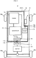
- Fig. 1 is a block diagram showing an outline configuration of an apparatus having mounted thereon an electric power supply system P according to a first embodiment of the present invention.
- Fig. 1 shows a vehicle V as an example of the apparatus having mounted thereon the electric power supply system P.
- the vehicle V includes the electric power supply system P and a vehicle body D.
- the vehicle body D of the vehicle V includes wheels Wa, Wb, Wc, Wd, a request indication unit A, a vehicle connector 17b, an inverter J, and a motor 18.
- the motor 18 is connected to drive wheels Wc, Wd among the wheels Wa to Wd.
- the motor 18 drives the drive wheels Wc, Wd in rotation so that the vehicle V travels.
- the motor 18 is operated by electric power that is supplied from the electric power supply system P.
- a request for each of the current and voltage to be supplied to the motor 18 varies depending on a situation where the vehicle V is traveling. For example, at a time of acceleration or uphill traveling of the vehicle V, a request for increasing the current to be supplied to the motor 18 is issued.
- the motor 18 represents one example of the electrical load device of the present invention.
- the drive wheels Wc, Wd represent one example of a driving member of the present invention.
- the electric power supply system P is a drive source of the vehicle V.
- the electric power supply system P includes a generator 10, an engine 14, a control device 15, and a converter 16.
- the electric power supply system P does not output mechanical power to the outside of the electric power supply system P.
- the electric power supply system P outputs electric power to the outside of the electric power supply system P.
- the electric power supply system P supplies electric power to the motor 18. Details of the electric power supply system P will be given later.
- the request indication unit A outputs a current request.
- the request indication unit A has an accelerator operator.
- the request indication unit A is operated by a driver of the vehicle V.
- the request indication unit A accordingly outputs a request for acceleration of the vehicle V.
- the request for acceleration of the vehicle V corresponds to a torque for driving the drive wheels Wc, Wd.
- the request for acceleration of the vehicle V also serves as an output request requesting an output of the vehicle V.
- the output of the vehicle V corresponds to an output of the motor 18.
- the request for acceleration of the vehicle V corresponds to a request for an output torque of the motor 18.
- the output torque of the motor 18 corresponds to a current supplied to the motor 18.
- the current request that the request indication unit A outputs to the electric power supply system P corresponds to a requirement of a current to be supplied to the motor 18. That is, the current request that the request indication unit A outputs to the electric power supply system P is a requirement of a current that the electric power supply system P outputs to the motor 18.
- the request indication unit A outputs the current request to the electric power supply system P. To be precise, the request indication unit A outputs a signal representing the request.
- the request indication unit A outputs a current request and a voltage request to the electric power supply system P. For example, in a situation requesting mainly an increase of the output torque of the motor 18, an increase of the current is requested. For example, in a situation requesting mainly an increase of the rotation speed of the motor 18, an increase of the voltage is requested.
- the electric power supply system P supplies a current to the motor 18 via the inverter J.
- the inverter J supplies to the motor 18 a current for driving the motor 18.
- the motor 18 of this embodiment is a three-phase brushless motor.
- the inverter J converts a DC output from the electric power supply system P into a three-phase current with phases shifted by 120 degrees.
- the phases of the three-phase current correspond to the three phases of the three-phase brushless motor, respectively.
- the motor 18 is operated by electric power that is supplied from the electric power supply system P via the inverter J.
- the inverter J may be included in the motor 18.
- an induction motor or a stepper motor may be adopted as the motor 18.
- a DC motor with brushes may also be adopted as the motor 18.
- the motor 18 is a DC motor, the inverter J is not provided.
- Fig. 2 is a system configuration diagram showing an outline configuration of the electric power supply system P shown in Fig. 1 .
- the electric power supply system P of this embodiment constitutes an engine generator unit P' for driving the vehicle.
- the vehicle body D of the vehicle V shown in Fig. 1 has a storage part B.
- the engine generator unit P' is placed in the storage part B.
- the engine generator unit P' for driving the vehicle can be mounted to and dismounted from the vehicle body D of the vehicle V (see Fig. 1 ).
- the engine generator unit P' for driving the vehicle includes the electric power supply system P, a connector 17a, and a control connector 19a.
- the electric power supply system P includes the generator 10, the engine 14, and the control device 15.
- the electric power supply system P also includes a fuel tank 10A, an air cleaner 10B, a muffler 10D, and the converter 16.
- the generator 10, the engine 14, the control device 15, the connector 17a, the fuel tank 10A, the air cleaner 10B, the muffler 10D, and the converter 16 are integrally assembled. Accordingly, the engine 14, the control device 15, the connector 17a, the fuel tank 10A, the air cleaner 10B, the muffler 10D, and the converter 16, which form the engine generator unit P', are integrally mounted to or dismounted from the vehicle body D of the vehicle V.
- the engine generator unit P' is an apparatus that is, as a physically single body, mounted to and dismounted from the vehicle body D.
- the engine generator unit P' is configured such that all parts included in the engine generator unit P' form a single body that is mountable to and dismountable from the vehicle body D. All parts included in the engine generator unit P' are, for example, the generator 10, the engine 14, the control device 15, and the like.
- the engine generator unit P' may be configured to be mounted to and dismounted from the vehicle body D without using a fixture member (e.g., a screw) that is attachable to and detachable from the vehicle body D and the engine generator unit P'.
- the engine generator unit P' may be configured to be mounted to and dismounted from the vehicle body D by a mounting mechanism provided in the vehicle body D and/or the engine generator unit P'.
- the engine generator unit P' may be configured to be mounted to and dismounted from the vehicle body D with a fixture member that is attachable to and detachable from the vehicle body D and the engine generator unit P'.
- the engine generator unit P' may be configured such that a worker can perform an operation for mounting or dismounting the engine generator unit P' by physically and directly operating the engine generator unit P' with or without use of a tool.
- the engine generator unit P' may be configured such that the operation for mounting or dismounting the engine generator unit P' can be performed by machine equipment without a worker performing a direct and physical operation on the engine generator unit P'.
- the engine generator unit P' may be configured as a physically single body that is mountable to and dismountable from the vehicle body D and that has at least one component thereof individually mountable to and dismountable from the vehicle body D.
- the engine generator unit P' may be configured such that it can be refueled while being mounted to the vehicle body D of the vehicle V.
- the engine generator unit P' may be configured such that it can be refueled with an engine oil while being mounted to the vehicle body D of the vehicle V.
- the engine generator unit P' can be dismounted from the vehicle V for repair.
- the engine generator unit P' can be easily transferred to an apparatus other than the vehicle V.
- the engine generator unit P' can be easily transferred to a vehicle of a different type than the vehicle V.
- the vehicle of the different type has a structure capable of storing the engine generator unit P' and includes a mating connector connectable with the connector 17a.
- one engine generator unit P' is shared among a plurality of types of vehicles.
- the connector 17a For mounting the engine generator unit P' to the vehicle body D of the vehicle V, the connector 17a is connected to the vehicle connector 17b (see Fig. 1 ) provided in the vehicle body D of the vehicle V.
- the connector 17a and the vehicle connector 17b relay the current supplied from the generator 10 of the electric power supply system P to the motor 18.
- the control connector 19a For mounting the engine generator unit P' to the vehicle body D of the vehicle V, the control connector 19a is connected to a vehicle control connector 19b (see Fig. 1 ) provided in the vehicle body D of the vehicle V.
- the control connector 19a and the vehicle control connector 19b relay a signal representing the amount of operation supplied from the request indication unit A to the control device 15 of the electric power supply system P.
- the control connector 19a may be integrated with the connector 17a.
- the engine 14 is an internal combustion engine.
- the engine 14 causes fuel combustion.
- the engine 14 outputs mechanical power.
- the engine 14 includes an output shaft C.
- the output shaft C is, for example, a crankshaft.
- Fig. 2 schematically shows the connection relationship between the engine 14 and the output shaft C.
- the engine 14 includes a cylinder 142, a piston 143, a connecting rod 145, and a crank case 146.
- the cylinder 142 and the piston 143 define a combustion chamber.
- the piston 143 and the crankshaft serving as the output shaft C are connected via the connecting rod 145.
- the engine 14 is supplied with air via the air cleaner 10B.
- the engine 14 is supplied with a fuel from the fuel tank 10A.
- the engine 14 causes the fuel supplied from the fuel tank 10A to combust in the combustion chamber, so that the piston 143 moves to-and-fro.
- the crankshaft serving as the output shaft C converts the to-and-fro movement into rotational power.
- the engine 14 outputs mechanical power through the output shaft C.
- An exhaust gas generated by the combustion in the engine 14 is discharged via the muffler 10D.
- the rotation speed of the output shaft C represents the rotation speed of the engine 14.
- the engine 14 is not connected to the drive wheels Wc, Wd by any mechanical component.
- a mechanical system of the electric power supply system P is closed in the electric power supply system P. That is, all of the rotational power output from the engine 14 is converted into power other than mechanical power in the electric power supply system P.
- the rotational power generated by the engine 14 is converted exclusively into electric power. More specifically, all of the mechanical power generated by the engine 14, except a loss, is converted into electric power by the generator 10.
- the electric power resulting from the conversion in the generator 10 is, in the outside of the electric power supply system P, converted into mechanical power by the motor 18.
- the electric power supply system P does not directly drive an external mechanism arranged outside the electric power supply system P by using rotational power of the engine 14. Therefore, the control of the rotational power of the engine 14 is less influenced by constraints inherent in operation characteristics of the external mechanism. This provides a high degree of freedom in terms of controlling the rotational power of the engine 14.
- the engine 14 includes an engine output adjustment unit 141.
- the engine output adjustment unit 141 adjusts the rotational power of the engine 14.
- the engine output adjustment unit 141 includes a throttle valve adjustment mechanism 141a and a fuel injection device 141b.
- the throttle valve adjustment mechanism 141a adjusts the amount of air taken in by the engine 14.
- the fuel injection device 141b supplies the fuel to the engine 14.
- the engine output adjustment unit 141 controls the amount of air taken in and the amount of fuel injected by the engine 14. In this manner, the engine output adjustment unit 141 adjusts the rotational power output from the engine 14. For example, the engine output adjustment unit 141 increases the amount of air taken in and the amount of fuel injected by the engine 14. This causes an increase of the rotational power of the engine 14. As the rotational power of the engine 14 increases, the rotation speed of the output shaft C increases. The rotation speed of the output shaft C represents the rotation speed of the engine 14.
- the engine output adjustment unit 141 changes the rotational power of the engine 14, thus adjusting the voltage and current generated by the generator 10.
- the generator 10 is mechanically connected to the engine 14.
- the generator 10 is connected to the output shaft C of the engine 14.
- the generator 10 is directly connected to the output shaft C.
- the generator 10 receives the rotational power from the engine 14, and supplies a current to the motor 18.
- the generator 10 is, for example, attached to the crank case 146 of the engine 14.
- the generator 10 may be arranged in a position distant from the crank case 146.
- the generator 10 includes a rotor 11, a stator 12, and a supply current adjustment unit 131.
- the generator 10 is a three-phase brushless generator.
- the rotor 11 and the stator 12 constitute a three-phase brushless generator.
- the rotor 11 includes permanent magnets.
- the rotor 11 includes a plurality of magnetic pole parts 111 and a back yoke part 112.
- the magnetic pole part 111 is made of a permanent magnet.
- the back yoke part 112 is made of, for example, a ferromagnetic material.
- the magnetic pole parts 111 are arranged between the back yoke part 112 and the stator 12.
- the magnetic pole parts 111 are attached to the back yoke part 112.
- the plurality of magnetic pole parts 111 are arranged so as to align in a circumferential direction Z about the rotation axis of the rotor 11, that is, so as to align in the direction of rotation of the rotor 11.
- the plurality of magnetic pole parts 111 are arranged such that N-poles and S-poles alternate with respect to the circumferential direction Z.
- the generator 10 is a three-phase brushless generator of permanent magnet type. A winding for supplying a current is not provided on the rotor 11.
- the stator 12 is arranged opposite to the rotor 11.
- the stator 12 includes a plurality of windings 121 and a stator core 122.
- the stator core 122 is made of, for example, a ferromagnetic material.
- the stator core 122 forms a magnetic circuit of the stator 12.
- the plurality of windings 121 are wound on the stator core 122.
- the stator core 122 includes a core main body 122a (see Fig. 3(A) ) and a plurality of teeth 122b.
- the core main body 122a functions as a yoke.
- the plurality of teeth 122b extends from the core main body 122a toward the rotor 11.
- the plurality of teeth 122b protrudes from the core main body 122a toward the rotor 11.
- the teeth 122b extending toward the rotor 11 have their distal end surfaces opposite to the magnetic pole parts 111 of the rotor 11 with an air gap therebetween.
- the teeth 122b of the stator core 122 and the magnetic pole parts 111 of the rotor 11 directly face each other.
- the plurality of teeth 122b which are arranged at intervals with respect to the circumferential direction Z, align in the circumferential direction Z.
- Each of the plurality of windings 121 is wound on each of the plurality of teeth 122b.
- Each winding 121 is wound so as to pass through a slot between the plurality of teeth 122b.
- Each winding 121 corresponds to any of the three phases, namely, U-phase, V-phase, and W-phase.
- the windings 121 corresponding to U-phase, V-phase, and W-phase are arranged in order in the circumferential direction Z.
- the rotor 11 is connected to the output shaft C of the engine 14.
- the rotor 11 is rotated along with rotation of the output shaft C.
- the rotor 11 has the magnetic pole parts 111 rotating in a state where the magnetic pole parts 111 are opposite to the teeth 122b of the stator core 122.
- magnetic fluxes linked with the windings 121 change.
- an induced voltage is generated in the windings 121.
- the generator 10 supplies a generated current to the motor 18.
- the current output from the generator 10 is supplied to the motor 18.
- the current output from the generator 10 is supplied to the motor 18.
- the current output from the generator 10 is supplied to the motor 18 via the converter 16 and the inverter J.
- a voltage output from the generator 10 is supplied to the motor 18 via the converter 16 and the inverter J.
- the rotor 11 and the stator 12 have an axial gap structure.
- the rotor 11 and the stator 12 are opposite to each other with respect to the direction (axial direction) X of the rotation axis of the rotor 11.
- the plurality of teeth 122b included in the stator 12 protrude in the axial direction X from the core main body 122a.
- the axial direction X is a direction in which the rotor 11 and the stator 12 are opposite to each other.
- the supply current adjustment unit 131 adjusts the current to be supplied from the generator 10 to the motor 18. For adjusting the current to be supplied to the motor 18, the supply current adjustment unit 131 changes the inductance of the winding 121.
- the supply current adjustment unit 131 changes the magnetic resistance of a magnetic circuit for the winding 121, which passes through the stator core 122. In this manner, the supply current adjustment unit 131 changes the inductance of the winding 121.
- the supply current adjustment unit 131 is a current adjustment mechanism.
- the magnetic circuit for the winding 121 is, for example, a closed-loop circuit.
- the magnetic circuit for the winding 121 is a circuit that passes through an internal path of the winding 121, then goes out from one end portion (the end portion close to the rotor) of the internal path of the winding 121, then enters one end portion (the end portion close to the rotor) of an internal path of an adjacent winding 121, then passes through the internal path of the adjacent winding 121, then goes out from the other end portion (the end portion remote from the rotor) of the internal path of the adjacent winding 121, and then enters the other end portion (the end portion remote from the rotor) of the internal path of the winding 121.
- the internal path of the winding 121 is a path provided within the winding 121 so as to extend in the direction in which the rotor 11 and the stator 12 are opposite to each other.
- the magnetic circuit for the winding 121 partially has a non-magnetic gap such as an air gap.
- the magnetic circuit for the winding 121 is, for example, made up of the stator core 122 and a non-magnetic gap.
- the control device 15 of the electric power supply system P controls the current to be supplied to the motor 18 (see Fig. 1 ) serving as the electrical load device. Upon a requirement of increasing the current to be supplied to the motor 18, the control device 15 controls the current to be supplied to the motor 18. Upon a requirement of increasing power to be output to the motor 18 serving as the electrical load device, the control device 15 controls the current to be supplied to the motor 18.
- the control device 15 is connected to the engine output adjustment unit 141 and the supply current adjustment unit 131.
- a current request issued to the electric power supply system P is output from the request indication unit A in accordance with the amount of operation of the request indication unit A.
- the control device 15 controls the engine output adjustment unit 141 and the supply current adjustment unit 131 in accordance with the current request output from the request indication unit A.
- the electric power supply system P of this embodiment adjusts a balance between the inductance of the generator 10 and the rotation of the engine 14 by means of the control device 15. Therefore, the vehicle body D (see Fig. 1 ) serving as the apparatus on which the electric power supply system P is mounted does not need to adjust the balance.
- the electric power supply system P is dealt with like a battery unit that receives the current request.
- the vehicle V having the electric power supply system P mounted thereon is able to obtain a current responsive to the request from the electric power supply system P, without the need of its built-in control device that directly controls the amount of air taken in and the amount of fuel injected by the engine 14.
- the control device 15 includes a current request receiving unit 151 and an adjustment control unit 152.
- the control device 15 is constituted of a microcontroller, for example.
- the control device 15 includes a central processing unit (not shown) and a storage device (not shown).
- the central processing unit performs computational processing based on a control program.
- the storage device stores data concerning programs and computation.
- the current request receiving unit 151 and the adjustment control unit 152 are implemented by the central processing unit executing programs.
- the current request receiving unit 151 receives a current request.
- the current request represents a requirement of the current to be supplied to the motor 18.
- the current request receiving unit 151 receives a current request which is output in accordance with the amount of operation of the request indication unit A.
- the adjustment control unit 152 controls the engine output adjustment unit 141 and the supply current adjustment unit 131. Thus, the adjustment control unit 152 controls the current to be supplied to the motor 18.
- the adjustment control unit 152 performs the control so as to increase the current to be supplied to the motor 18. That is, to increase output power of the motor 18, the adjustment control unit 152 performs the control so as to increase the current to be supplied to the motor 18.
- the electric power supply system P also includes the converter 16.
- the converter 16 rectifies the current output from the generator 10.
- the converter 16 converts a three-phase AC output from the generator 10 into a DC.
- the converter 16 outputs the DC.
- the converter 16 has an inverter circuit, for example.
- the converter 16 has a three-phase bridge inverter circuit, for example.
- the three-phase bridge inverter circuit includes switching elements Sa corresponding to the respective three phases. On/off operations of the switching elements Sa are controlled based on a signal supplied from a position sensor (not shown) that detects the rotation position of the rotor 11.
- the operation of the converter 16 is controlled by the control device 15.
- the current to be supplied to the motor 18 can be adjusted by, for example, changing the timing for turning on/off the switching elements of the converter 16 relative to a predetermined phase angle in the three-phase AC. Even when the engine 14 and the generator 10 are in operation, the rotation of the motor 18 can be stopped by, for example, the converter 16 blocking the current generated by the generator 10. A stopped state of the vehicle V can be maintained in this manner.
- the adjustment made by the converter 16 is mainly for limiting the current generated by the generator 10.
- the adjustment made by the converter 16 is different from controlling the current by changing the inductance of the generator 10. The following description will be given under the assumption that the limiting of the current made by the converter 16 is kept to a minimum.
- the converter 16 has a bridge circuit including diodes. That is, the converter 16 may be configured as a rectifier. In such a case, the control of the current by the control device 15 is not performed.
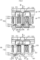
- Fig. 3(A) and Fig. 3(B) are schematic diagrams explaining the adjustment made by the supply current adjustment unit 131 provided in the generator 10 shown in Fig. 2 .
- Fig. 3(A) shows a state in which the inductance of the winding 121 is set to the highest settable value.
- Fig. 3(B) shows a state in which the inductance of the winding 121 is set to a value lower than that of Fig. 3(A) .
- Fig. 3(A) illustrates a part of the rotor 11 and a part of the stator 12 provided in the generator 10.
- the generator 10 of this embodiment includes an SPM (Surface Permanent Magnet) generator.
- the rotor 11 and the stator 12 are opposite to each other. More specifically, the magnetic pole parts 111 of the rotor 11 and the teeth 122b of the stator core 122 of the stator 12 are opposite to each other with the air gap therebetween.
- the magnetic pole parts 111 are exposed to the stator 12.
- the supply current adjustment unit 131 changes the magnetic resistance of a magnetic circuit F22 for the winding 121, which passes through the stator core 122. In this manner, the supply current adjustment unit 131 changes the inductance of the winding 121, to adjust the current to be supplied to the motor 18. In more detail, the supply current adjustment unit 131 moves the position of the stator core 122 relative to the winding 121. This is how the supply current adjustment unit 131 changes the magnetic resistance of the magnetic circuit F22 for the winding 121, which passes through the stator core 122.
- the windings 121 are secured to a casing (not shown) of the generator 10.
- the stator core 122 is supported on the casing such that the stator core 122 is freely movable in the axial direction X relative to the windings 121.
- the windings 121 are not secured to the teeth 122b.
- a gap is ensured between each winding 121 having a cylindrical shape and each tooth 122b. The gap is to such an extent that the tooth 122b is freely movable relative to the winding 121.
- the supply current adjustment unit 131 moves the stator core 122 so as to move the teeth 122b in a direction into and out of the cylindrically wound windings 121. In this embodiment, the supply current adjustment unit 131 moves the stator core 122 in the axial direction X.
- the control device 15 operates the supply current adjustment unit 131 in accordance with the current request.
- the supply current adjustment unit 131 is schematically illustrated in the form of a rack-and-pinion mechanism and a motor.
- mechanisms other than the illustrated one may be adopted as the supply current adjustment unit 131 that moves the stator core 122.
- a mechanism including a cylindrical member that is arranged concentric with a stator core and in threaded engagement with the stator core may be adopted.
- Such a mechanism is able to move the stator core in the axial direction X by, for example, rotating the cylindrical member relative to the stator core.
- the supply current adjustment unit 131 moves the position of the stator core 122 relative to the winding 121 while maintaining the position of the stator core 122 relative to the rotor 11.
- the broken lines Q express that the rotor 11 moves in conjunction with the stator core 122 in the axial direction X.
- a structure for maintaining the relative position between the rotor 11 and the stator core 122 is implemented by, for example, a bearing part 113 rotatably supporting the rotor 11. The position of the bearing part 113 is fixed relative to the stator core 122.
- Fig. 3(A) and Fig. 3(B) illustrate primary magnetic fluxes F1 generated by the magnetic pole parts 111.
- the line of each magnetic flux F1 represents a primary magnetic circuit through which the magnetic flux F1 generated by the magnetic pole part 111 passes.
- the magnetic circuit through which the magnetic flux F1 passes will be referred to as a magnetic circuit F1.
- the primary magnetic flux F1 generated by the magnetic pole part 111 flows through the magnetic pole part 111, the air gap between the magnetic pole part 111 and the tooth 122b, the tooth 122b, the core main body 122a, and the back yoke part 112.
- the magnetic circuit F1 is made up of the magnetic pole part 111, the air gap between the magnetic pole part 111 and the tooth 122b, the tooth 122b, the core main body 122a, and the back yoke part 112.
- Fig. 3(A) and Fig. 3(B) show three teeth 122b among the plurality of teeth 122b arranged in the circumferential direction.
- Fig. 3(A) and Fig. 3(B) show a state in which the magnetic pole part 111 is opposite to the middle tooth 122b among the three teeth 122b.
- the amount of magnetic flux generated by the magnetic pole part 111 and linked with the winding 121 changes.
- the change of the amount of magnetic flux linked with the winding 121 causes an induced voltage to occur in the winding 121. That is, power is generated.
- the induced voltage caused in the winding 121 depends on the amount of magnetic flux linked with the winding 121.
- the magnetic resistance of the magnetic circuit F1 depends mainly on the magnetic resistance of the air gap between the tooth 122b and the magnetic pole part 111.
- the magnetic resistance of the air gap between the tooth 122b and the magnetic pole part 111 depends on an air gap length L1 of the air gap between the tooth 122b and the magnetic pole part 111.
- the induced voltage caused in the winding 121 depends on the air gap length L1 of the air gap between the tooth 122b and the magnetic pole part 111.
- Fig. 3(A) and Fig. 3(B) illustrate a primary magnetic flux F2 generated by a current flowing in the winding 121.
- the magnetic flux F2 is generated by the current flowing in the winding 121 at the time of power generation.
- the line of each magnetic flux F2 represents a primary magnetic circuit through which the magnetic flux F2 generated by the current in the winding 121 passes.
- the magnetic circuit through which the magnetic flux F2 passes will be referred to as a magnetic circuit F2.
- the magnetic circuit F2 is the magnetic circuit for the winding 121.
- the magnetic circuit F2 for the winding 121 is made up of a path passing through the inside of the winding 121 and providing the minimum magnetic resistance of the entire magnetic circuit F2.
- the magnetic circuit F2 passes through the stator core 122.
- the magnetic circuit F2 passes through adjacent teeth 122b.
- three teeth 122b among the plurality of teeth 122b arranged in the circumferential direction are shown.
- the magnetic circuit F2 for the winding 121 wound on the middle tooth 122b among the three teeth 122b is illustrated as a typical example.
- a magnetic circuit F2 for a certain winding 121 passes through a tooth 122b having the certain winding 121 wound thereon and two teeth 122b adjacent to the certain tooth 122b.
- the primary magnetic flux F2 generated by the current in the winding 121 passes through the teeth 122b, the core main body 122a, and the air gap between the two adjacent teeth 122b.
- the magnetic circuit F2 is made up of the teeth 122b, the core main body 122a, and the air gap between the two adjacent teeth 122b.
- the magnetic circuit F2 passing through the stator core 122 includes one air gap. A portion of the magnetic circuit F2 including the air gap is indicated by the bold line. The bold-line portion of the magnetic circuit F2 including the air gap will be simply referred to as an air gap F2a.
- the air gap F2a exists between the winding 121 and the rotor 11.
- the air gap F2a included in the magnetic circuit F2 exists between the winding 121 and the rotor 11 and between the adjacent teeth 122b.
- the air gap F2a is a non-magnetic gap.
- a portion of the magnetic circuit F2 corresponding to the air gap F2a is provided so as to connect respective portions of the two adjacent teeth 122b opposite to the rotor 11.
- the magnetic circuit F2 for the winding 121 includes the air gap F2a between the two adjacent teeth 122b.
- the magnetic circuit F2 does substantially not include the back yoke part 112 of the rotor 11. Most of the magnetic flux F2 generated by the current in the winding 121 passes through the air gap between the two adjacent teeth 122b without going to the back yoke part 112 of the rotor 11, for the following reasons.
- the magnetic pole part 111 is considered simply as a magnetic flux path.
- the magnetic pole part 111 is made of a permanent magnet which has a magnetic permeability that is as low as air.
- the magnetic pole part 111 can therefore be considered as equivalent to air for the magnetic circuit F2. Since the magnetic pole part 111 is equivalent to air, the substantial air gap length of the air gap between the stator 12 and the rotor 11 is equal to a distance L11 from the tooth 122b to the back yoke part 112.
- the distance L11 from the tooth 122b to the back yoke part 112 includes the thickness of the magnetic pole part 111 with respect to the axial direction X. Thus, the distance L11 is longer than a distance L1 from the tooth 122b to the magnetic pole part 111.
- the amount of the magnetic flux F2 generated by the current in the winding 121 is smaller than the amount of magnetic flux generated by the permanent magnet of the magnetic pole part 111. Most of the magnetic flux F2 generated by the current in the winding 121 is less likely to reach the back yoke part 112 across the air gap length L11. Little of the magnetic flux F2 generated by the current in the winding 121 passes through the back yoke part 112.
- the inductance of the winding 121 is set to the highest settable value.
- the air gap F2a included in the magnetic circuit F2 has the highest magnetic resistance among portions of the magnetic circuit F2.
- the air gap F2a has a higher magnetic resistance than that of a remaining portion F2b of the magnetic circuit F2 other than the air gap F2a.
- the inductance of the winding 121 depends on the magnetic resistance of the magnetic circuit F2 for the winding 121.
- the inductance of the winding 121 is in reverse proportion to the magnetic resistance of the magnetic circuit F2 for the winding 121.
- the magnetic resistance of the magnetic circuit F2 for the winding 121 is the magnetic resistance of the magnetic circuit F2 through which the magnetic flux F2 generated by the current in the winding 121 flows.
- the magnetic resistance of the magnetic circuit F2 for the winding 121 which passes through the stator core 122, includes the magnetic resistance of the air gap F2a between the two adjacent teeth 122b.
- the magnetic flux F2 generated by the current in the winding 121 passes through both the stator 12 and the rotor 11. As described above, however, most of the magnetic flux generated by the current in the winding 121 passes through the air gap F2a between the two adjacent teeth 122b without going to the back yoke part 112 of the rotor 11.
- the magnetic resistance to the winding 121 depends more strongly on the magnetic resistance of the magnetic circuit F2 passing through the stator 12 than on the magnetic resistance of the magnetic circuit F1 passing through the rotor 11. That is, the inductance of the winding 121 depends more strongly on the magnetic resistance of the magnetic circuit F2, which passes through the stator core 122 when viewed from the winding 121 side, than on the magnetic resistance of the magnetic circuit F1, which passes through the rotor 11 when viewed from the winding 121 side. Accordingly, the inductance of the winding 121 substantially depends on the magnetic resistance of the magnetic circuit F2, which passes through the stator core 122 when viewed from the winding 121 side.
- the supply current adjustment unit 131 moves the position of the stator core 122 relative to the windings 121. In this manner, the supply current adjustment unit 131 changes the magnetic resistance of the magnetic circuit F2 for the winding 121. This is how the supply current adjustment unit 131 changes the inductance of the winding 121. For example, in case of the supply current adjustment unit 131 moving the stator core 122 in a direction indicated by the arrow X1, the teeth 122b of the stator core 122 are moved in the direction out of the cylindrically wound windings 121.
- Fig. 3(B) shows a state having a lower inductance than that of the state shown in Fig. 3(A) .
- the length of the air gap F2a constituting the magnetic circuit F2 increases. This increases the magnetic resistance of the air gap F2a between the winding 121 and the rotor 11. That is, the magnetic resistance of the air gap F2a, which has a magnetic resistance that is highest, increases. As a result, the magnetic resistance of the magnetic circuit F2 for the winding 121, which passes through the stator core 122, increases. Consequently, the inductance of the winding 121 decreases.
- the supply current adjustment unit 131 changes the magnetic resistance of the air gap F2a which has a magnetic resistance that is highest. In this manner, the supply current adjustment unit 131 changes the magnetic resistance of the magnetic circuit F2 passing through the adjacent teeth 122b. This can cause a larger change of the inductance of the winding 121 as compared with, for example, changing the magnetic resistance of a portion other than the air gap F2a.
- the supply current adjustment unit 131 changes the inductance of the winding 121 such that the change rate of the inductance of the winding 121 is higher than the change rate of the magnetic flux linked with the winding 121. This is how the supply current adjustment unit 131 adjusts the current.
- the supply current adjustment unit 131 of the generator 10 moves the position of the stator core 122 relative to the windings 121 while maintaining the position of the stator core 122 relative to the rotor 11.
- the supply current adjustment unit 131 moves the stator core 122 in the direction of the arrow X1, the rotor 11 is accordingly moved in the direction of the arrow X1. Therefore, the position of the stator core 122 relative to the rotor 11 is maintained. This can suppress a change of the air gap length L1 between the teeth 122b and the magnetic pole parts 111, which otherwise might be caused by movement of the stator core 122. Accordingly, a change of the magnetic flux F1 flowing from the magnetic pole part 111 to the stator core 122 is suppressed. That is, a change of the magnetic flux F1 linked with the winding 121 is suppressed.
- Fig. 4 is a circuit diagram schematically showing an equivalent circuit of the winding 121 of the generator 10 shown in Fig. 3(A) .
- FIG. 4 The circuit depicted in Fig. 4 is simplified for the purpose of outlining a change of the voltage and current generated by the generator 10.
- illustration of the converter 16 and the inverter J is omitted on the assumption that their states are fixed.
- the winding 121 in an electrical sense includes an AC voltage source 121A, an inductor 121B, and a resistance 121C.
- the AC voltage source 121A outputs an induced voltage E which depends mainly on a magnetic flux ⁇ linked with the winding 121. More specifically, the induced voltage E depends on the product of the magnetic flux F1 and the rotation speed ⁇ of the rotor 11.
- An inductance L of the inductor 121B depends mainly on the magnetic resistance of the magnetic circuit F2 for the winding 121, which passes through the stator core 122.
- a resistance value R of the resistance 121C is a winding resistance.
- Impedance Zg of the winding 121 is schematically expressed as ⁇ L 2 + R 2 1 / 2 .
- the supply current adjustment unit 131 moves the position of the stator core 122 relative to the winding 121 in accordance with the current request.
- the supply current adjustment unit 131 changes the magnetic resistance of the magnetic circuit F2 for the winding 121, which passes through the stator core 122.
- the supply current adjustment unit 131 changes the inductance of the winding 121L.
- the change of the inductance L leads to a change of the impedance Zg. As a result, a current I to be supplied from the generator 10 is adjusted.
- the supply current adjustment unit 131 changes the inductance of the winding 121 such that the change rate of the magnetic flux ⁇ linked with the winding 121 is lower than the change rate of the inductance of the winding 121L. This is how the supply current adjustment unit 131 adjusts the current I. Accordingly, the current is adjusted with less change of the induced voltage E.
- the engine output adjustment unit 141 changes the rotation speed of the engine 14, to change the rotation speed ⁇ of the rotor 11, so that the voltage to be supplied to the motor 18 is adjusted.
- the output (rotational power) of the engine 14 mainly changes the rotation speed of the output shaft C, that is, the rotation speed ⁇ of the rotor 11.
- the rotation speed ⁇ of the rotor 11 influences both the induced voltage E of the winding 121 and the impedance (( ⁇ L) 2 +R 2 ) 1/2 . Therefore, adoption of only the method of changing the rotation speed of the output shaft C of the engine 14 cannot avoid high interaction between the supply voltage and the supply current.
- the generator 10 moves the position of the stator core 122 relative to the winding 121 in accordance with the current request, to change the magnetic resistance of the magnetic circuit F2 for the winding 121, which passes through the stator core 122.
- the inductance of the winding 121 is changed. Therefore, the ratio of a current change to a voltage change obtained when changing the magnetic resistance of the magnetic circuit F2 for the winding 121 is different from that obtained when changing the rotation speed ⁇ of the rotor 11.
- the generator of this embodiment is able to adjust the current to be supplied to the motor 18 with less interaction between the voltage change and the current change as compared with when, for example, only the rotation speed of the output shaft C of the engine 14 is changed by the engine output adjustment unit 141.
- a movement of the position of the stator core 122 relative to the winding 121 causes a change of the magnetic resistance of the magnetic circuit F2 for the winding 121.
- the inductance of the winding 121L is changed, so that the current is adjusted.
- This embodiment can gradually change the inductance L because the change of the inductance L is implemented by a change of the magnetic resistance of the magnetic circuit F2 for the winding 121, which passes through the stator core 122.
- changing the substantial number of turns of the winding is also conceivable as a method for changing the inductance.
- a terminal provided at an end of the winding and a terminal provided in the middle of the winding are selectively switched for use as a current output terminal.
- a terminal provided in the middle of the winding is short-circuited to another terminal. This changes the substantial number of turns which affect the current. As a result, the inductance is changed.
- the magnetic resistance of the stator core 122 is changed, so that the inductance of the winding 121L is changed.
- the inductance of the winding 121L can be changed gradually. This can suppress a rapid increase of the voltage occurring in the winding 121. It is therefore possible that a component having a low breakdown voltage is connected to the generator 10. This provides a high efficiency. This also eliminates the need to provide the switching element for switching the current. This also allows use of a relatively thin wire for the winding. A size increase of the generator 10 is suppressed.
- Fig. 5 is a flowchart of the operation of the electric power supply system P.
- the electric power supply system P performs a control process.
- the control device 15 controls the current and voltage to be supplied to the motor 18.
- the control device 15 repeats the control process shown in Fig. 5 .
- the control of the voltage and current output from the electric power supply system P will be described with reference to Figs. 2 to 3 , too.
- the current request receiving unit 151 of the control device 15 receives a request for electric power (S11).
- the current request receiving unit 151 receives a current request.
- the current request represents a requirement of the current to be supplied to the motor 18.
- the current request receiving unit 151 receives the amount of operation of the request indication unit A.
- the current request receiving unit 151 obtains the current request based on the amount of operation of the request indication unit A. More specifically, the current request receiving unit 151 obtains the current request based on the amount of operation of the request indication unit A, the state of traveling of the vehicle V, setting of the target fuel efficiency, and setting of the followability to the operation.
- the adjustment control unit 152 controls the current to be supplied to the motor 18 based on the current request received by the current request receiving unit 151 (S12).
- the adjustment control unit 152 controls the current to be supplied to the motor 18 based on a request for increasing the current. More specifically, upon a request for increasing the current, the adjustment control unit 152 performs the control so as to increase the current to be supplied to the motor 18.
- the adjustment control unit 152 controls the current and voltage to be supplied to the motor 18.
- the adjustment control unit 152 controls the current and voltage to be supplied to the motor 18 based on the amount of operation of the request indication unit A.
- the adjustment control unit 152 is configured to control both the supply current adjustment unit 131 and the engine output adjustment unit 141.
- the adjustment control unit 152 controls the amount of adjustment made by the supply current adjustment unit 131 and the amount of adjustment made by the engine output adjustment unit 141.
- the adjustment control unit 152 controls a distribution between the amount of adjustment made by the supply current adjustment unit 131 and the amount of adjustment made by the engine output adjustment unit 141.
- the control device 15 controls a distribution between the increase in the amount of the current and the increase in the amount of the voltage.
- a typical example of a control with a large increase in the amount of the voltage and a typical example of a control with a large increase in the amount of the current will be described.
- the typical example of the control with a large increase in the amount of the voltage will be referred to as a voltage control.
- the typical example of the control with a large increase in the amount of the current will be referred to as a current control.
- the control device 15 performs any of the current control, the voltage control, or a combination of the current control and the voltage control, in accordance with the request received.
- the control device 15 directs the engine output adjustment unit 141 (see Fig. 2 ) to increase the rotational power of the engine 14.
- the control device 15 directs the engine output adjustment unit 141 to increase the amount of air taken in and the amount of fuel injected by the engine 14.
- the increase of the power of the engine 14 leads to an increase of the rotation speed of the engine 14 which means the rotation speed ⁇ of the rotor 11 of the generator 10.
- the control device 15 does not direct the supply current adjustment unit 131 to perform the adjustment for reducing the inductance L of the winding 121.
- the supply current adjustment unit 131 maintains the state in which the teeth 122b of the stator core 122 are completely received in the cylindrical shapes of the windings 121, as shown in Fig. 3 .
- control device 15 upon a request for increasing the voltage, the control device 15 does not direct the supply current adjustment unit 131 to reduce the inductance L of the winding 121.
- the control device 15 directs the engine output adjustment unit 141 to increase the rotational power of the engine 14.
- the induced voltage E of the AC voltage source 121A shown in Fig. 4 increases.
- the induced voltage E is substantially in proportion to the rotation speed ⁇ . This results in an increase of the voltage output from the electric power supply system P. That is, the voltage supplied to the motor 18 increases.
- the motor 18 While the motor 18 is rotating at a constant speed according to the voltage that has been already supplied, an induced voltage generated by the rotation occurs in the motor 18.
- the induced voltage of the motor 18 is generated in such a direction that the current flowing from the electric power supply system P to the motor 18 is impeded. Therefore, the current flowing from the electric power supply system P to the motor 18 is relatively small. That is, impedance Z18 of the motor 18 itself is high. In such a state, the current flowing in the winding 121 of the generator 10 is relatively small. Accordingly, the impedance Zg of the winding 121 is less influential to the output voltage of the electric power supply system P.
- the impedance Zg of the winding 121 increases.
- the increase of the impedance Zg of the winding 121 is, however, less influential to the output voltage of the electric power supply system P when the impedance Z18 of the motor 18 is high. Therefore, the voltage supplied to the motor 18 increases substantially in accordance with the increase of the rotation speed ⁇ .
- the increase of the voltage supplied to the motor 18 leads to an increase of the rotation speed of the motor 18.
- the control device 15 directs the supply current adjustment unit 131 to adjust the position of the stator core 122 such that the inductance of the winding 121L is reduced.
- the supply current adjustment unit 131 adjusts the position of the stator core 122 so as to increase the magnetic resistance of the magnetic circuit F2 for the winding 121, which passes through the stator core 122.
- the supply current adjustment unit 131 moves the stator core 122 in such a direction that the teeth 122b of the stator core 122 are moved out of the cylindrical shapes of the windings 121 shown in Fig. 3 . As a result, the inductance L of the winding 121 is reduced.
- the control device 15 directs the supply current adjustment unit 131 to adjust the magnetic resistance of the magnetic circuit F2 for the winding 121 in accordance with a current request. In this manner, the supply current adjustment unit 131 changes the inductance of the winding 121. This is how to control the current to be supplied to the motor 18 serving as the electrical load device.
- the control device 15 directs the supply current adjustment unit 131 to increase the magnetic resistance of the magnetic circuit F2 for the winding 121, in accordance with a request for increasing the current.
- the supply current adjustment unit 131 reduces the inductance of the winding 121. This can increase the current to be supplied to the motor 18 serving as the electrical load device.
- the supply current adjustment unit 131 changes the inductance of the winding 121 by changing the magnetic resistance of the air gap F2a existing between the winding 121 and the rotor 11.
- the magnetic pole parts 111 moving along with rotation of the rotor 11 cause an alternating magnetic field to occur between the windings 121 and the rotor 11.
- reducing the magnetic resistance of the air gap F2a existing between the winding 121 and the rotor 11 leads to a reduction of an alternating magnetic field loss.
- a core loss in the magnetic circuit F2 passing through the air gap F2a is reduced.
- the reduction of the loss enables a large current to be output. Accordingly, the current to be supplied to the motor 18 serving as the electrical load device can be adjusted to an increased degree.
- the control device 15 directs the engine output adjustment unit 141 ( Fig. 2 ) to increase the rotational power of the engine 14. More specifically, the control device 15 directs the engine output adjustment unit 141 to increase the amount of air taken in and the amount of fuel injected by the engine 14. The increase of the rotational power of the engine 14 leads to an increase of the rotation speed of the engine 14 which means the rotation speed ⁇ of the rotor 11 of the generator 10.
- the induced voltage E of the AC voltage source 121A increases.
- the induced voltage E is substantially in proportion to the rotation speed ⁇ .
- the increase of the induced voltage E results in an increase of the current output from the electric power supply system P. That is, the current to be supplied to the motor 18 increases.
- the control device 15 performs the control by using, for example, a map in which the inductance, the rotation speed, and the output current are stored in association with one another.
- the map is obtained by, for example, preliminarily measuring or simulating the relationship between the rotation speed and the output current of the engine 14 for a plurality of inductances L.
- the relationship shown in the graph of Fig. 9 is one example of the relationship between the rotation speed and the output current of the engine 14.
- the control device 15 sets the requested current as a target.
- the control device 15 controls the engine output adjustment unit 141 and the supply current adjustment unit 131 so as to obtain the inductance L that enables the target current to be achieved at the minimum rotation speed.
- control device 15 is configured to control the engine output adjustment unit 141 and the supply current adjustment unit 131 by, for example, calculating expressions instead of using the map.
- the control device 15 is configured to control both the supply current adjustment unit 131 and the engine output adjustment unit 141.
- the control device 15 directs the supply current adjustment unit 131 to reduce the inductance of the winding 121 while directing the engine output adjustment unit 141 to increase the rotational power of the engine 14.
- an entire period in which the supply current adjustment unit 131 reduces the inductance of the winding 121 has an overlap with an entire period in which the engine output adjustment unit 141 increases the rotational power of the engine 14.
- a period in which the supply current adjustment unit 131 is reducing the inductance of the winding 121 has an overlap with a period in which the engine output adjustment unit 141 is increasing the rotational power of the engine 14.
- the rotation speed ⁇ of the rotor 11 of the generator 10 increases due to the adjustment made by the engine output adjustment unit 141.
- the inductance L of the winding 121 is reduced due to the adjustment made by the supply current adjustment unit 131.
- an increase of the impedance Zg of the winding 121 which depends on the product of the rotation speed ⁇ and the inductance L, is suppressed. Accordingly, a greater increase of the current is obtained as compared with when the inductance of the winding 121L is not reduced.
- the excessive increase of the rotational power causes an excessive increase of the induced voltage E.
- the current supplied to the motor 18 decreases. This makes the impedance Zg of the winding 121 less influential. Accordingly, a voltage corresponding to the induced voltage E, which has excessively increased, is output from the generator 10.
- the converter 16 is arranged between the generator 10 and the motor 18, though not shown in Fig. 4 .
- a high voltage corresponding to the induced voltage E is applied to the switching elements of the converter 16.
- a switching element having a high breakdown voltage for withstanding a high voltage has a high on-resistance. Thus, a large loss is caused by the switching element.
- the electric power supply system P of this embodiment is configured such that the supply current adjustment unit 131 reduces the inductance L of the winding 121 in response to a request for an increase of the current.
- an increase of the impedance Zg of the winding 121 is suppressed.
- This allows a greater increase of the current to be obtained from the increase of the rotational power of the engine 14 as compared with when, for example, the inductance L is not reduced.
- an excessive increase of the rotational power in response to a request for increasing the current is suppressed.
- This improves the fuel efficiency of the engine 14.
- an excessive increase of the output voltage is suppressed. This allows adoption of a switching element with a low breakdown voltage, which has an on-resistance that is low. Accordingly, a high fuel efficiency is obtained.
- the electric power supply system P of this embodiment is able to enhance separation between the adjustment of the current to be supplied to the electrical load device and the adjustment of the voltage to be supplied to the electrical load device.
- the electric power supply system P is, therefore, able to make adjustment more responsive to each of the current request and the voltage request.
- Fig. 6(A) and Fig. 6(B) are schematic diagrams explaining the adjustment made by a supply current adjustment unit provided in a generator 20 of an electric power supply system according to the second embodiment.
- Fig. 6(A) shows a state in which the inductance of a winding 221 is set to the highest settable value.
- Fig. 6(B) shows a state in which the inductance of the winding 221 is set to a value lower than that of Fig. 6(A) .
- a magnetic circuit F21 is a magnetic circuit through which a magnetic flux generated by a magnetic pole part 211 passes.
- a magnetic circuit F22 is a magnetic circuit for the winding 221.
- the magnetic circuit F22 for the winding 221 is made up of a path passing through the inside of the winding 221 and providing the minimum magnetic resistance of the entire magnetic circuit F22.
- the magnetic circuit F22 passes through the stator core 222.
- the magnetic circuit F22 passes through two adjacent teeth 222b.
- the magnetic circuit F22 passing through the stator core 222 includes an air gap F22a.
- the air gap F22a exists between the winding 221 and the rotor 21.
- the air gap F22a included in the magnetic circuit F22 exists between the winding 221 and the rotor 21 and between the two adjacent teeth 222b.
- the air gap F22a included in the magnetic circuit F22 is provided so as to connect respective portions of the two adjacent teeth 222b opposite to the rotor 21.
- the magnetic circuit F22 for the winding 221 does not pass through a back yoke part 212 of the rotor 21.
- the magnetic circuit F22 for the winding 221 includes the air gap F22a between the two adjacent teeth 122b.
- the air gap F22a included in the magnetic circuit F22 has the highest magnetic resistance among portions of the magnetic circuit F22.
- the air gap F22a has a higher magnetic resistance than that of a remaining portion F22b of the magnetic circuit F22 other than the air gap F22a.
- a supply current adjustment unit 231 moves the windings 221 in accordance with a current request.
- the supply current adjustment unit 231 changes the magnetic resistance of the magnetic circuit F22 for the winding 221.
- the supply current adjustment unit 231 changes the inductance of the winding 221, to adjust the current to be supplied to the motor 18 (see Fig. 1 ).
- the supply current adjustment unit 231 moves the windings 221 without moving the stator core 222 of the stator 22.
- stator core 222 is secured to a casing (not shown).
- the rotor 21 is rotatably supported on the casing.
- the rotor 21 is secured with respect to the axial direction X.
- the windings 221 are supported on the casing such that the windings 221 are freely movable in the axial direction X relative to the casing.
- the supply current adjustment unit 231 moves the windings 221 in the direction that causes the teeth 222b to move into and out of the cylindrical shapes of the windings 221.
- the supply current adjustment unit 231 moves the windings 221 in the axial direction X.
- the supply current adjustment unit 231 moves the windings 221 in a direction indicated by the arrow X2, for example. All the windings 221 wound on the teeth 222b provided in the generator 20 are moved integrally.
- the control device 15 operates the supply current adjustment unit 231 in accordance with the current request.
- Fig. 6(B) shows a state having a lower inductance than that of the state shown in Fig. 6(A) .
- the state shown in Fig. 6(B) is a state after the windings 221 are moved in the direction of the arrow X2.
- the supply current adjustment unit 231 moves the windings 221 alone, in accordance with the current request. In this manner, the supply current adjustment unit 231 moves the position of the stator core 222 relative to the windings 221. Thus, the supply current adjustment unit 231 changes the magnetic resistance of the magnetic circuit F22 for the winding 221, which passes through the stator core 222.
- the teeth 222b of the stator core 222 are pulled out of the windings 221.
- Pulling the teeth 222b out of the windings 221 reduces the volume of the stator core 222 existing within the windings 221.
- the length of the air gap F22a included in the magnetic circuit F22 for the winding 221 increases.
- the magnetic resistance of the magnetic circuit F22 for the winding 221 increases. Consequently, the inductance of the winding 221 decreases.
- the supply current adjustment unit 231 changes the magnetic resistance of the air gap F22a which has a magnetic resistance that is highest.
- the supply current adjustment unit 231 changes the magnetic resistance of the magnetic circuit F22 passing through the adjacent teeth 222b. Accordingly, a larger change of the inductance of the winding 221 is likely to occur as compared with, for example, changing the magnetic resistance of the portion F22b other than the air gap F22a.
- the supply current adjustment unit 231 changes the magnetic resistance of the magnetic circuit F22 for the winding 221.
- the supply current adjustment unit 231 changes the inductance of the winding 221.
- the supply current adjustment unit 231 increases the magnetic resistance of the magnetic circuit F22 for the winding 221 in accordance with a request for increasing the current.
- the supply current adjustment unit 231 reduces the inductance of the winding 221.
- the current to be supplied to the motor 18 (see Fig. 1 ) serving as the electrical load device can be increased.
- the supply current adjustment unit 231 changes the inductance of the winding 221 by changing the magnetic resistance of the air gap F22a existing between the winding 221 and the rotor 21. This results in a reduction of an alternating magnetic field loss. Accordingly, the current to be supplied to the motor 18 serving as the electrical load device can be adjusted to an increased degree.
- Fig. 7 is a schematic diagram showing a generator 30 of an electric power supply system according to the third embodiment.
- a stator core 322 provided in the generator 30 shown in Fig. 7 includes a plurality of first stator core parts 323 and a second stator core part 324.
- Each of the plurality of first stator core parts 323 is provided with a facing portion 323a that is opposite to the rotor 31 with an air gap therebetween.
- the plurality of first stator core parts 323 are annularly arranged at intervals. That is, the plurality of first stator core parts 323 align in the circumferential direction Z.
- the plurality of first stator core parts 323 function as primary teeth in the stator 32.
- the first stator core parts 323 may also be referred to as first teeth 323.
- the length of the facing portion 323a of the first stator core part 323 with respect to the circumferential direction Z is longer than the length of any portion of the first stator core part 323 other than the facing portion 323a with respect to the circumferential direction Z.
- a winding 321 is wound on each of the first stator core parts 323.
- the second stator core part 324 is arranged at a position opposite to the rotor 31 across the first stator core parts 323.
- the first stator core parts 323 are arranged between the second stator core part 324 and the rotor 31.
- the second stator core part 324 is not provided with the facing portion 323a that is opposite to the rotor 31.
- the second stator core part 324 includes a stator yoke portion 324a having an annular shape and a plurality of second teeth 324b.
- the second teeth 324b protrude from the stator yoke portion 324a and toward the first stator core part 323.
- the number of the second teeth 324b is equal to the number of the first stator core parts 323.
- the stator yoke portion 324a and the second teeth 324b may be configured such that substantially all of the magnetic fluxes passing through the second teeth 324b flow through the stator yoke portion 324a. That is, the second teeth 324b may be formed integral with the stator yoke portion 324a. Alternatively, the second teeth 324b may be formed separate from the stator yoke portion 324a such that they are attachable to the stator yoke portion 324a.
- the second teeth 324b are arranged so as to align in the circumferential direction Z.
- the plurality of second teeth 324b are annularly arranged at intervals equal to the intervals of the first stator core parts 323.
- a supply current adjustment unit 331 of the generator 30 of this embodiment moves the position of a part of the stator core 322 relative to the winding 321.
- the supply current adjustment unit 331 moves one of the plurality of first stator core parts 323 and the second stator core part 324 relative to the other. In this manner, the supply current adjustment unit 331 changes the magnetic resistance for the winding 321. This is how the supply current adjustment unit 331 adjusts the current to be supplied to the motor 18.
- first stator core parts 323 are secured to a casing (not shown).
- the second stator core part 324 is supported so as to be rotatable in the circumferential direction Z.
- the supply current adjustment unit 331 rotates the second stator core part 324 in the circumferential direction Z about the rotation axis of the rotor 31. In this manner, the supply current adjustment unit 331 moves the second stator core part 324 from a first state (see Fig. 8(A) ) to a second state (see Fig. 8(B) ).
- Fig. 8(A) is a schematic diagram showing that the stator 32 illustrated in Fig. 7 is in the first state.
- Fig. 8(B) is a schematic diagram showing that the stator 32 illustrated in Fig. 7 is in the second state.
- the inductance of the winding 321 is set to the highest settable value.
- the inductance of the winding 321 is set to a value lower than that of Fig. 8(A) .
- each of the plurality of second teeth 324b is positioned with respect to the circumferential direction Z so as to confront each of the plurality of first stator core parts 323.
- an air gap length L32 between each of the plurality of first stator core parts 323 and the second stator core part 324 is shorter than an air gap length L33 between adjacent ones of the plurality of first stator core parts 323.
- the air gap length L33 is the length of an air gap formed between respective portions of the first stator core parts 323, each of the portions arranged between the winding 321 and the rotor 31 with respect to a direction in which the rotor 31 and the stator 32 are opposite to each other.
- each of the plurality of second teeth 324b is positioned between adjacent ones of the first stator core parts 323 with respect to the circumferential direction Z.
- an air gap length L34 between each of the plurality of first stator core parts 323 and the second stator core part 324 is longer than the air gap length L33 between adjacent ones of the plurality of first stator core parts 323.
- Fig. 8(A) and Fig. 8(B) illustrate a magnetic circuit F31 through which a magnetic flux generated by a magnetic pole part 311 passes, and a magnetic circuit F32 for the winding 321.
- the magnetic circuit F32 for the winding 321 is made up of a path passing through the inside of the winding 321 and providing the minimum magnetic resistance of the entire magnetic circuit F32.
- the magnetic circuit F32 passes through the stator core 322.
- the magnetic circuit F32 passes through two adjacent first stator core parts 323 (first teeth 323).
- the magnetic circuit F32 includes three air gaps. A portion of the magnetic circuit F32 corresponding to an air gap between the two adjacent first stator core parts 323 (first teeth 323) will be referred to as an air gap F32a. Portions of the magnetic circuit F32 corresponding to air gaps each between each of the two adjacent first stator core parts 323 (first teeth 323) and the second stator core part 324 will be referred to as air gaps F32c.
- the air gap F32a between the two adjacent first stator core parts 323 (first teeth 323) exists between the winding 321 and the rotor 31.
- the air gap F32a included in the magnetic circuit F32 exists between the winding 321 and the rotor 31 and between the two adjacent first stator core parts 323 (first teeth 323).
- the air gap F32a is provided so as to connect mutually opposite end surfaces of the respective two adjacent first stator core parts 323 (first teeth 323).
- the air gap length L32 between each of the plurality of first stator core parts 323 (first teeth 323) and the second stator core part 324 is shorter than the air gap length L33 between adjacent ones of the plurality of first stator core parts 323 (first teeth 323).
- the air gap length L33 is the largest air gap length in the magnetic circuit F32.
- the air gap F32a between the adjacent first stator core parts 323 has the highest magnetic resistance among portions of the magnetic circuit F32 for the winding 321.
- the magnetic resistance of the air gap F32a is higher than the magnetic resistance of any of remaining portions F32b, F32c, and F32d of the magnetic circuit F32 other than the air gap F32a.
- the magnetic resistance of the air gap F32a is higher than the magnetic resistance of the air gap F32c between the first stator core part 323 and the second stator core part 324.
- a magnetic flux F32 generated by the current in the winding 321 flows through the adjacent first stator core parts 323 and the second stator core part 324, as shown in Fig. 8(A) .
- the magnetic resistance of the magnetic circuit F32 for the winding 321, which passes through the stator core 322, depends on the air gap length L33 between the adjacent first stator core parts 323.
- the air gap length L33 is the largest air gap length in the magnetic circuit F32.
- the magnetic flux F31 generated by the magnetic pole part 311 passes through the two adjacent first stator core parts 323.
- the magnetic flux F31 passes through one magnetic pole part 311, a gap between the magnetic pole part 311 and the first stator core part 323, the first stator core part 323, the second stator core part 324, an adjacent first stator core part 323, a gap between the first stator core part 323 and the magnetic pole part 311, an adjacent magnetic pole part 311, and the back yoke part 312.
- the magnetic circuit F31 for the magnetic pole part 311 passes through the two adjacent first stator core parts 323 and the second stator core part 324.
- the air gap length L34 between each of the plurality of first stator core parts 323 and the second stator core part 324 is longer than the air gap length L33 between adjacent ones of the plurality of first stator core parts 323. Therefore, the magnetic resistance of the magnetic circuit F32 for the winding 321, which passes through the stator core 322, is strongly influenced by the air gap length L34 between the first stator core part 323 and the second stator core part 324. As a result, in the second state, the magnetic resistance of the magnetic circuit F32 for the winding 321 is higher than the magnetic resistance in the first state.
- the magnetic flux F31 generated by the magnetic pole part 311 passes through one magnetic pole part 311, the gap between the magnetic pole part 311 and the first stator core part 323, and the first stator core part 323.
- the magnetic flux F31 flows from the first stator core part 323 directly to the adjacent first stator core part 323.
- the magnetic flux F31 generated by the magnetic pole part 311 passes through a gap between the two adjacent first stator core parts 323.
- the path of the magnetic flux F31 generated by the magnetic pole part 311 is switched as described above. In the second state, even if the path of the magnetic flux F31 is not switched, at least a portion of the magnetic flux F31 generated by the magnetic pole part 311 is increased, the portion passing through the gap between the two adjacent first stator core parts 323.
- the change rate of the inductance of the winding 321 is higher than the change rate of the magnetic flux that is generated by the magnetic pole part 311 and linked with the winding 321.
- the inductance of the winding 321 is liable to be in reverse proportion to the magnetic resistance for the winding 321. Therefore, the inductance of the winding 321 in the second state is lower than the inductance of the winding 321 in the first state.
- the supply current adjustment unit 331 moves one of the plurality of first stator core parts 323 and the second stator core part 324 relative to the other so as to shift from the first state (see Fig. 8(A) ) to the second state (see Fig. 8(B) ) in accordance with the request for increasing the current, for example. In this manner, the supply current adjustment unit 331 changes the magnetic resistance for the winding 321. Thus, the supply current adjustment unit 331 changes the inductance of the winding 321. This is how to adjust the current to be supplied to the motor 18 (see Fig. 1 ).
- the supply current adjustment unit 331 changes the magnetic resistance of the air gap F32a.
- the supply current adjustment unit 331 changes the magnetic resistance of the air gap F32a without changing the air gap length L33 between the first stator core parts 323 serving as the adjacent teeth.
- the supply current adjustment unit 331 changes the magnetic resistance of the magnetic circuit F32 passing through the first stator core parts 323 serving as the adjacent teeth.
- the air gap F32a has the highest magnetic resistance among portions of the magnetic circuit F32. Therefore, a change of the inductance of the winding 321 can be greater than that obtained when, for example, changing the magnetic resistance of portions other than the air gap F32a.
- the supply current adjustment unit 331 changes the inductance of the winding 321 by changing the magnetic resistance of the air gap F32a existing between the winding 321 and the rotor 31. This results in a reduction of an alternating magnetic field loss. Accordingly, the current to be supplied to the motor 18 serving as the electrical load device can be adjusted to an increased degree.
- Fig. 9 is a graph showing output current characteristics relative to the rotation speed of the rotor 31 of the generator 30 shown in Fig. 7 .
- the rotation speed of the rotor 31 is, therefore, also usable to adjust the output current of the electric power supply system.
- the rotation speed of the rotor 31 corresponds to the rotation speed of the output shaft C (see Fig. 2 ) of the engine 14.
- the increase of the output current in accordance with the increase of the rotation speed is steep in a region where the rotation speed of the rotor 31 is relatively low.
- the increase of the output current in accordance with the increase of the rotation speed is gentle in a region where the rotation speed is relatively high. That is, the change rate of the output current relative to the change of the rotation speed is low in the region where the rotation speed is relatively high.
- the vehicle V (see Fig. 1 ) traveling at a high speed requires a further increase of the output torque of the motor 18 when the vehicle starts uphill traveling or overtakes another vehicle during traveling. A request for an increased current is issued in such a situation.
- the induced voltage of the winding 321 is substantially in proportion to the rotation speed of the rotor 31.
- a significant increase of the rotation speed causes a significant increase of the induced voltage.
- electrical components need to have a high breakdown voltage. This leads to a decrease in efficiency due to an increased breakdown voltage of the electrical components.
- the control device 15 controls the supply current adjustment unit 331 (see Fig. 6 ) in addition to the engine output adjustment unit 141 (see Fig. 2 ). In this manner, the control device 15 changes the magnetic resistance of the magnetic circuit F32 for the winding 321 in accordance with the current request. Thus, the control device 15 changes the inductance of the winding 321. This is how to adjust the current to be supplied to the motor 18.
- the supply current adjustment unit 331 moves the second stator core part 324 from the first state (see Fig. 8(A) ) to the second state (see Fig. 8(B) ). As a result, the output current characteristics change from the one represented by the broken line H1 to the one represented by the solid line H2 in Fig. 9 .
- the control device 15 reduces the inductance while increasing the rotation speed of the engine 14 to N2. This increases the output current to I2.
- the control device 15 controls the adjustment made by the engine output adjustment unit 141 and the adjustment made by the supply current adjustment unit 331 in an integrated manner.
- the control device 15 controls the engine output adjustment unit 141 and the supply current adjustment unit 331 as follows.
- the supply current adjustment unit 331 starts a process of reducing the inductance of the winding 121 before the engine output adjustment unit 141 terminates a process of increasing the rotational power of the engine 14. That is, there is an overlap between a period in which the supply current adjustment unit 331 is reducing the inductance of the winding 121 and a period in which the engine output adjustment unit 141 is increasing the rotational power of the engine 14.
- control performed by the control device 15 is able to provide a smooth increase of the current supplied from the electric power supply system P to the motor 18.
- occurrence of a situation can be suppressed in which the rotational power of the engine 14 excessively increases before the output current of the generator 30 reaches a requested current value in the process of adjusting the rotational power.
- control device 15 A voltage control performed by the control device 15 is described. Upon a request for increasing the voltage, the control device 15 does not reduce the inductance L. The control device 15 directs the engine output adjustment unit 141 (see Fig. 2 ) to increase the rotational power of the engine 14 without directing the supply current adjustment unit 331 to reduce the inductance L of the winding 321.
- control device 15 directs the engine output adjustment unit 141 to increase the rotational power of the engine 14, while maintaining the supply current adjustment unit 331 (see Fig. 7 ) in the first state (see Fig. 8(A) ) which corresponds to the broken line H1 in the graph of Fig. 9 .
- the induced voltage E (see Fig. 4 ) generated in the generator 30 is substantially in proportion to the rotation speed ⁇ .
- a situation requesting an increase of the voltage generally occurs when impedance Zm of the motor 18 itself is high.
- the impedance Zg of the winding 321 is less influential to the output voltage of the electric power supply system P. Therefore, a voltage according to the induced voltage E is output from the electric power supply system P.
- the electric power supply system P is able to respond to a request for increasing the voltage, without directing the supply current adjustment unit 331 to reduce the inductance L of the winding 321.
- a commonly-used generator that is unable to change the inductance can provide output current characteristics as represented by the solid line H2 of Fig. 9 , it is necessary to increase the thickness of the winding or the amount of magnets. Increasing the thickness of the winding or the amount of magnets leads to a size increase of the electric power supply system itself. As a result, the mountability to vehicle and the portability of the electric power supply system P are deteriorated. If a commonly-used generator that is unable to change the inductance is configured so as to provide output current characteristics as represented by the solid line H2, such generator cannot provide output current characteristics as represented by the broken line H1.
- a DC-DC converter configured to input and output electric power capable of driving the vehicle V, however, cannot avoid a size increase of its component such as a built-in transformer in response to an increase of required electric power.
- the control device 15 controls the supply current adjustment unit 331 so as to change the magnetic resistance of the magnetic circuit F32 for the winding 321 in accordance with the current request.
- the control device 15 changes the inductance of the winding 321. This enables the control device 15 to adjust the current in accordance with the current request without increasing the thickness of the winding or the amount of magnets.
- the generator 30 includes the supply voltage adjustment unit 344 in addition to the supply current adjustment unit 331.
- the supply voltage adjustment unit 344 is under control of the control device 15.
- the supply voltage adjustment unit 344 changes a linkage flux that is output from the magnetic pole part 311 of the rotor 31 and linked with the winding 321. In this manner, the supply voltage adjustment unit 344 changes the induced voltage of the winding 321. This is how the supply voltage adjustment unit 344 adjusts the voltage to be supplied to the motor 18. To be specific, the supply voltage adjustment unit 344 moves the rotor 31 in the axial direction X. Thus, the supply voltage adjustment unit 344 changes an air gap length L31 between the rotor 31 and the stator 32.
- Such a movement of the rotor 31 in the axial direction X is implemented by, for example, the supply voltage adjustment unit 344 configured to move a bearing part 313 in the axial direction X, the bearing part 313 supporting the rotor 31 in a rotatable manner.
- the change of the air gap length L31 between the rotor 31 and the stator 32 leads to a change of the magnetic resistance between the rotor 31 and the stator 32.
- the amount of the magnetic flux generated by the magnetic pole part 311 and linked with the winding 321 is changed.
- the voltage generated by the generator 30 is changed accordingly.
- the electric power supply system of this embodiment is able to adjust the voltage to be supplied to the motor 18 in a way other than by the engine output adjustment unit 141 adjusting the rotational power of the engine 14. This provides an increased degree of freedom in terms of controlling, resulting in suppression of a decrease in fuel efficiency.
- the supply voltage adjustment unit 344 is capable of more reduction of a variation in the linkage flux linked with the winding 321, the variation caused by an operation of the supply current adjustment unit 331, the more reduction achieved in the following manner.
- the linkage flux that is output from the magnetic pole part 311 of the rotor 31 and linked with the winding 321 flows through the stator core 322. Specifically, the linkage flux that is output from the magnetic pole part 311 and linked with the winding 321 flows through the first stator core part 323 and the second stator core part 324.
- the supply voltage adjustment unit 344 changes the air gap length L31 between the rotor 31 and the stator 32 so as to compensate for a variation in the linkage flux linked with the winding 321, the variation caused by the operation of the supply current adjustment unit 33. This can reduce the variation in the linkage flux linked with the winding 321, the variation caused by the operation of the supply current adjustment unit 331.
- the supply current adjustment unit 33 in combination with the compensation made by the supply voltage adjustment unit 344, is able to adjust the current while less influenced by voltage constraints.
- the generator 30 includes both the supply current adjustment unit 331 and the supply voltage adjustment unit 344.
- the supply voltage adjustment unit is not indispensable in the electric power supply system of the present invention.
- the third embodiment described above with reference to the current characteristics graph of Fig. 9 illustrates that the current to be supplied to the motor 18 can be adjusted while controlling the inductance.
- the current to be supplied to the motor 18 can be adjusted while controlling the inductance.
- the rotor and the stator having an axial gap structure are illustrated as an example.
- the electric power supply system of the present invention is also applicable to a radial gap structure in which a rotor and a stator are opposite to each other with an air gap therebetween with respect to a radial direction.
- the axial direction X ( Fig. 3 ) defined in the axial gap structure of these embodiments is one example of the direction in which the rotor and the stator of the present invention are opposite to each other.
- the rotor and the stator are opposite to each other with respect to the radial direction.
- the generator including an SPM generator is illustrated as an example.
- the generator of the present invention may be an IPM (Interior Permanent Magnet) generator.
- the air gap illustrated in the embodiments described above is one example of the non-magnetic gap.
- the non-magnetic gap is a gap made of a single type of a non-magnetic material or a plurality of types of non-magnetic materials. No particular limitation is put on the non-magnetic material. Examples of the non-magnetic material include air, aluminum, and resins. It is preferable that the non-magnetic gap includes at least an air gap.
- the configuration in which the rotor 11 is connected directly to the output shaft C of the engine 14 is illustrated as a specific example of the configuration in which the rotor 11 is connected to the engine 14.
- the output shaft C of the engine 14 and the rotor 11 of the generator 10 may be connected with interposition of a transmission mechanism as typified by a belt, a gear, or a drive shaft.
- control device 15 configured to concurrently control both the engine output adjustment unit 141 and the supply current adjustment unit 131 for a current control is illustrated as an example of the control device. This, however, is not limiting the present invention. It may be possible that the control device controls the engine output adjustment unit and the supply current adjustment unit at different timings.
- control device controls both the engine output adjustment unit and the supply current adjustment unit upon each current increase request.
- control device controls both the engine output adjustment unit and the supply current adjustment unit in response to a single current increase request and where the control device controls the engine output adjustment unit or the supply current adjustment unit in response to a single current increase request.
- control device may be configured to control both the engine output adjustment unit and the supply current adjustment unit in response to a single current increase request or to control the engine output adjustment unit or the supply current adjustment unit in response to a single current increase request, depending on at least the contents of the current increase request and/or the status of operation of the electric power supply system.
- the control device may be configured to, in a case of controlling both the engine output adjustment unit and the supply current adjustment unit in response to a single current increase request, start the control of at least one of the engine output adjustment unit and the supply current adjustment unit during a period in which the single current increase request is issued. In such a case, the control device may continue the control of at least one of the engine output adjustment unit and the supply current adjustment unit after the single current increase request is issued.
- the current increase request is a request for increasing the current, and it does not include a request for maintaining the increased current. It may be possible that the voltage is changed in accordance with the current control at a time of the current control. It may be possible that the current is changed in accordance with the voltage control at a time of the voltage control.
- control device 15 configured to receive a current request and a voltage request from the request indication unit A is illustrated as an example of the control device. This, however, is not limiting the present invention. In a possible example, the control device may be configured to receive a current request from a device that outputs the current request and a voltage request from another device that outputs the voltage request.
- control device 15 configured to perform the current control, the voltage control, and the combination of the current control and the voltage control is illustrated as an example of the control device.
- the control device may perform the current control and the voltage control alone. Alternatively, the control device may perform the current control alone.
- the accelerator operator is illustrated as an example of the request indication unit A.
- the current request of the present invention may not always need to be an output of the accelerator operator.
- the following is some examples of the request indication unit and the current request issued by the request indication unit:
- the embodiments described above illustrate the example in which the supply current adjustment unit 131 under control of the control device 15 reduces the inductance of the winding 121 by reducing the magnetic resistance of the magnetic circuit F2 for the winding 121 in accordance with the request for increasing the current. It is however not always necessary that the reduction of the magnetic resistance of the magnetic circuit for the winding implemented by the supply current adjustment unit of the present invention is in accordance with the request for increasing the current.
- the embodiments described above illustrate the example in which the control device configured to receive a signal is provided.
- the current request issued to the electric power supply system is not limited to an electrical signal. It may be also acceptable that the control device of the present invention is operated by, for example, a wire connected to an operation lever. In such a configuration, the supply current adjustment unit may move the stator core by using a force transmitted from the wire.
- the engine output adjustment unit 141 including the throttle valve adjustment mechanism 141a and the fuel injection device 141b is illustrated as an example of the engine output adjustment unit. It is not always necessary that the engine output adjustment unit uses both the throttle valve adjustment mechanism and the fuel injection device for adjustment of the rotational power. For example, the engine output adjustment unit may adjust the rotational power by using one of the throttle valve adjustment mechanism and the fuel injection device.
- the engine output adjustment unit of the present invention may be, for example, a valve arrangement that adjusts the flow rate of a gaseous fuel.
- the engine of the present invention may use a liquid fuel or a gaseous fuel.
- the three-phase brushless motor is illustrated as an example of the motor 18.
- the motor 18 of the present invention may be a motor having the same structure as that of the generator described in this embodiment.
- the motor 18 may be structured so as to include the plurality of first stator core parts and the second stator core part and configured to move one of the first stator core part and the second stator core part relative to the other.
- the vehicle V including the electric power supply system P that supplies electric power to the motor 18 is illustrated as an example of the vehicle.
- the vehicle may be provided with a battery for storing electric power supplied from an electric power supply system.
- the motor of the vehicle may be driven by electric power stored in the battery, for example.
- the motor of the vehicle may be operated by electric power that is supplied concurrently from both the electric power supply system P and the battery, for example.
- the vehicle V having four wheels is illustrated as an example of the apparatus to which the electric power supply system is applied.
- Applications of the electric power supply system of the present invention are not limited thereto, and it may be applicable to a vehicle with three wheels or less, a vehicle with five wheels or more, and a vehicle with no wheel.
- the electric power supply system of the present invention is applicable to, for example, a vehicle including a motor that receives electric power for driving wheels.
- the electric power supply system of the present invention is applicable to, for example, motorcycles, motor tricycles, buses, trucks, golf carts, carts, ATVs (All-Terrain Vehicles), ROVs (Recreational Off-highway Vehicles), and track-type vehicles.
- the electric power supply system of the present invention is applicable to, for example, a vehicle in which a drive mechanism different from wheels is driven by a motor.
- the electric power supply system of the present invention is applicable to, for example, industrial vehicles typified by forklifts, snow blowers, agricultural vehicles, military vehicles, snowmobiles, construction machines, small planing boats (water vehicles), marine crafts, outboard engines, inboard engines, airplanes, and helicopters.
- the electric power supply system of the present invention is applicable to, for example, engine blowers, snow blowers, lawn mowers, agricultural implements, gas engine heat pumps, and general-purpose machines.
- the electric power supply system of the present invention is applicable to general-purpose engine generator apparatuses.
- an exemplary engine generator unit is illustrated as an example of the electric power supply system.
- the present invention is not limited to a unit.
- the electric power supply system may be structured such that individual component parts are separately mounted to an apparatus.
- the engine generator unit P' including the fuel tank 10A, the air cleaner 10B, and the muffler 10D is illustrated as an example of the engine generator unit.
- a fuel tank, an air cleaner, and a muffler are provided not in the engine generator unit but in the vehicle body of the vehicle V. That is, it suffices that the engine of the present invention includes at least a cylinder for fuel combustion to output rotational power, a piston, and an output shaft.
- the engine of the present invention does not include a fuel tank, an air cleaner, and a muffler.
- control device 15 constituted of a microcontroller is illustrated as an example of the control device. This, however, is not limiting the present invention.
- the control device may be constituted of a wired logic, for example.
- the change of the inductance of the winding is implemented by changing the magnetic resistance of the magnetic circuit for the winding, which passes through the stator core.
- the change of the magnetic resistance of the magnetic circuit for the winding, which passes through the stator core may be implemented in a plurality of stages or in a single stage, or may be implemented continuously.
- the output current characteristics of the generator may be changed in a plurality of stages or in a single stage, or may be changed continuously.
- the broken line H1 of Fig. 9 represents exemplary output current characteristics obtained when the magnetic resistance of the magnetic circuit for the winding, which passes through the stator core, is low.
- FIG. 9 represents exemplary output current characteristics obtained when the magnetic resistance of the magnetic circuit for the winding, which passes through the stator core, is high. That is, the output current characteristics of the generator shown in Fig. 9 are not to be interpreted as limiting the change of the magnetic resistance of the magnetic circuit for the winding, which passes through the stator core, to a two-stage change as illustrated in this embodiment.
- the output current characteristics represented by the broken line H1 and the solid line H2 of Fig. 9 are contained in the output current characteristics that are changed in a plurality of stages, in a single stage, or continuously.
- the magnetic resistance of the magnetic circuit for the winding, which passes through the stator core may be changed in two stages.
- a situation where the supply current adjustment unit changes the state of the generator from one of a high-resistance state and a low-resistance state to the other is described.
- the magnetic resistance of the magnetic circuit for the winding, which passes through the stator core is lower than that in the high-resistance state.
- the state of the generator is changed so as to increase the magnetic resistance of the magnetic circuit for the winding, which passes through the stator core; the state of the generator before the change is the low-resistance state and the state of the generator after the change is the high-resistance state.
- the state of the generator is changed so as to reduce the magnetic resistance of the magnetic circuit for the winding, which passes through the stator core; the state of the generator before the change is the high-resistance state and the state of the generator after the change is the low-resistance state.
- the absolute value of the magnetic resistance of the magnetic circuit for the winding, which passes through the stator core in each of the high-resistance state and the low-resistance state.
- the high-resistance state and the low-resistance state are defined in a relative sense.
- the inductance of the winding in the high-resistance state is lower than the inductance of the winding in the low-resistance state.
- exemplary output current characteristics of the generator in the low-resistance state correspond to the broken line H1 of Fig. 9
- exemplary output current characteristics of the generator in the high-resistance state correspond to the solid line H2 of Fig. 9
- the generator in the high-resistance state and the generator in the low-resistance state output an equal magnitude of current at the equal rotation speed (M).
- an output current characteristic curve means a curve representing the output current of the generator relative to the rotation speed of the rotor.
- the generator of the present invention is configured such that, in a case where the supply current adjustment unit changes the state of the generator from the low-resistance state to the high-resistance state, the generator in the high-resistance state (H2) is able to output a current (I2) when rotating at a rotation speed (M+) higher than the rotation speed (M), the current (I2) being larger than the maximum current that could be output by the generator in the low-resistance state (H1) rotating at the rotation speed (M+).
- the state of the generator is changed so as to increase the magnetic resistance of the magnetic circuit for the winding, which passes through the stator core, thus enabling the generator to output a large current that could not be output at a relatively high rotation speed before the change.
- the generator of the present invention is configured such that, in a case where the supply current adjustment unit changes the state of the generator from the high-resistance state to the low-resistance state, the generator in the low-resistance state (H1) is able to output a current when rotating at a rotation speed (M-) lower than the rotation speed (M), the current being larger than the maximum current that could be output by the generator in the high-resistance state (H2) rotating at the rotation speed (M-).
- the state of the generator is changed so as to reduce the magnetic resistance of the magnetic circuit for the winding, which passes through the stator core, thus enabling the generator to output a large current that could not be output at a relatively low rotation speed before the change.
- the generator of the present invention is configured such that the generator after the supply current adjustment unit changes the magnetic resistance of the magnetic circuit for the winding, which passes through the stator core, is able to output a current at the rotation speed (M- or M+) higher or lower than the rotation speed (M), the current being larger than the maximum current that the generator could output at the rotation speed (M- or M+) before the change.
Landscapes
- Engineering & Computer Science (AREA)
- Power Engineering (AREA)
- Transportation (AREA)
- Mechanical Engineering (AREA)
- Chemical & Material Sciences (AREA)
- Combustion & Propulsion (AREA)
- Physics & Mathematics (AREA)
- General Physics & Mathematics (AREA)
- Automation & Control Theory (AREA)
- Life Sciences & Earth Sciences (AREA)
- Sustainable Development (AREA)
- Sustainable Energy (AREA)
- Health & Medical Sciences (AREA)
- Biomedical Technology (AREA)
- General Health & Medical Sciences (AREA)
- Electric Propulsion And Braking For Vehicles (AREA)
- Control Of Eletrric Generators (AREA)
- Hybrid Electric Vehicles (AREA)
- Control Of Vehicle Engines Or Engines For Specific Uses (AREA)
- Control Of Ac Motors In General (AREA)
- Combined Controls Of Internal Combustion Engines (AREA)
- Permanent Magnet Type Synchronous Machine (AREA)
- Arrangement Or Mounting Of Propulsion Units For Vehicles (AREA)
Abstract
Description
- The present invention relates to an electric power supply system, a control device, a vehicle, and an engine generator unit for driving a vehicle.
- For example, Patent Literature 1 (PTL1) shows a vehicle. The vehicle shown in
Patent Literature 1 is a hybrid vehicle. This vehicle includes an engine, an accelerator pedal, a first rotary electric machine, a second rotary electric machine, and a drive wheel. The first rotary electric machine is coupled to an output shaft of the engine. The first rotary electric machine functions mainly as a generator. The second rotary electric machine is electrically connected to the first rotary electric machine. The second rotary electric machine functions mainly as a motor. By a current flowing in the first rotary electric machine and the second rotary electric machine, power generation and power running/consumption are performed. The second rotary electric machine is coupled to the drive wheel of the vehicle. - In the vehicle as shown in
Patent Literature 1, a depression of the accelerator pedal depressed by a driver represents a request for acceleration of the vehicle. The vehicle as shown inPatent Literature 1 is, if provided with an electronic-controlled throttle device, able to optionally adjust the amount of air taken in by the engine. The vehicle is, therefore, controlled in the following manner. A target output of the second rotary electric machine (motor) is determined based on the vehicle speed and the amount of depression of the accelerator pedal depressed by the driver. A target electric power to be generated by the first rotary electric machine (generator) is determined in accordance with the target output of the second rotary electric machine. A target output of the engine is determined in accordance with the target electric power to be generated. The amount of air taken in and the amount of fuel injected by the engine are controlled so as to achieve the target output. In this control, the first rotary electric machine is controlled in its generating electric power and the second rotary electric machine is controlled in its output. In a case where the vehicle as shown inPatent Literature 1 is configured with its accelerator pedal mechanically coupled with its engine throttle, the electric power generated by the first rotary electric machine and the output of the second rotary electric machine are controlled in accordance with an actual output of the engine. InPatent Literature 1, as described above, electric power (output) of the rotary electric machine is controlled so as to allow applications to various types of vehicles with different characteristics. - PTL1: Japanese Patent Application Laid-Open No.
2002-345109 - In the vehicle as shown in
Patent Literature 1, for example, to increase a current to be supplied to the second rotary electric machine serving as the motor, a control is performed so as to increase the amount of air taken in and the amount of fuel injected by the engine. The rotation speed of the engine increases, and as a result, the voltage output from the first rotary electric machine functioning as the generator increases. Here, there has been a problem in that the current output from the generator is less readily increased than the rotation speed of the generator. Therefore, an attempt to increase the current output from the generator requires an excessive increase of the output power of the engine. This may decrease the fuel efficiency. Dealing with the voltage, which increases in response to the increase of the output power of the engine, may also decrease the fuel efficiency. - An object of the present invention is to provide an electric power supply system, a control device, a vehicle, and an engine generator unit for driving a vehicle that are able to make adjustments responsive to a requirement of increasing a current resulting in suppression of a decrease in fuel efficiency.
- To solve the problems described above, the present invention adopts the following configurations.
- (1) An electric power supply system configured to supply electric power to an electrical load device that requires a current that can be variable,
the electric power supply system comprising:- an engine that outputs rotational power, the engine including an engine output adjustment unit that adjusts the rotational power;
- a generator that receives the rotational power from the engine and supplies a current to the electrical load device, the generator including a rotor, a stator, and a supply current adjustment unit, the rotor connected to the engine, the rotor including a permanent magnet, the stator arranged opposite to the rotor, the stator including a winding and a stator core with the winding wound thereon, the supply current adjustment unit configured to adjust the current to be supplied to the electrical load device, the adjustment implemented by changing an inductance of the winding, the change implemented by changing a magnetic resistance of a magnetic circuit for the winding, which passes through the stator core; and
- a control device configured to, upon a requirement of increasing the current to be supplied to the electrical load device, control the current to be supplied to the electrical load device by controlling both the engine output adjustment unit and the supply current adjustment unit that adjusts the current by changing the inductance of the winding.
In the electric power supply system of (1), the engine output adjustment unit adjusts the rotational power of the engine. In addition, the supply current adjustment unit changes the magnetic resistance of the magnetic circuit for the winding of the generator, which passes through the stator core. Thus, the supply current adjustment unit changes the inductance of the winding, to adjust the current to be supplied to the electrical load device.
In the generator, the ratio of a current change to a voltage change obtained when changing the magnetic resistance of the magnetic circuit for the winding, which passes through the stator core, is different from the ratio of a current change to a voltage change obtained when changing the rotational power of the engine. For example, a current change can be made larger relative to a voltage change by changing the magnetic resistance of the magnetic circuit for the winding, which passes through the stator core.
In the electric power supply system of (1), the control device controls both the engine output adjustment unit and the supply current adjustment unit. This is how the electric power supply system of (1) is able to increase the current to be supplied to the electrical load device while suppressing an excessive increase of the rotational power of the engine and an excessive increase of the voltage. In addition, the control device controls both the engine output adjustment unit and the supply current adjustment unit. This enables adjustment of the rotational power of the engine and adjustment of the inductance of the winding to be controlled in an integrated manner. Therefore, the engine output adjustment unit and the supply current adjustment unit are able to make adjustments for increasing the current to be supplied to the electrical load device while suppressing an excessive increase of the rotational power of the engine and an excessive increase of the voltage. Thus, a loss that may be caused by an excessive increase of the rotational power and an excessive increase of the voltage can be suppressed. Accordingly, the electric power supply system of (1) is able to make adjustments responsive to a requirement of increasing the current, resulting in suppression of a decrease in fuel efficiency. - (2) The electric power supply system of (1), wherein
the magnetic circuit for the winding, which passes through the stator core, includes at least one non-magnetic gap, and
the supply current adjustment unit adjusts the current to be supplied to the electrical load device, the adjustment implemented by changing the inductance of the winding, the change implemented by changing a magnetic resistance of a non-magnetic gap being among the at least one non-magnetic gap, the non-magnetic gap existing between the winding and the rotor.
In the configuration of (2), the supply current adjustment unit changes the inductance of the winding by changing the magnetic resistance of the non-magnetic gap existing between the winding and the rotor. The permanent magnet moving along with rotation of the rotor causes an alternating magnetic field to occur between the winding and the rotor. For example, reducing the magnetic resistance of the non-magnetic gap existing between the winding and the rotor leads to a reduction of an alternating magnetic field loss. This can increase the current relative to the rotational power supplied to the rotor. Accordingly, the current to be supplied to the electrical load device can be adjusted to an increased degree. - (3) The electric power supply system of (1) or (2), wherein
the magnetic circuit for the winding, which passes through the stator core, includes at least one non-magnetic gap, and
the supply current adjustment unit adjusts the current to be supplied to the electrical load device, the adjustment implemented by changing the inductance of the winding, the change implemented by changing a magnetic resistance of a non-magnetic gap being among the at least one non-magnetic gap, the magnetic resistance of the non-magnetic gap is highest when the inductance of the winding is set to the highest settable value.
The configuration of (3) changes the magnetic resistance of the non-magnetic gap which has a magnetic resistance that is highest when the inductance of the winding is set to the highest settable value. This makes it easy to increase the amount of change of the inductance of the winding. Accordingly, the current can be adjusted to an increased degree. - (4) The electric power supply system of any one of (1) to (3), wherein
the supply current adjustment unit adjusts the supply current by changing the inductance of the winding such that the change rate of a magnetic flux linked with the winding is lower than the change rate of the inductance of the winding, the change implemented by changing the magnetic resistance of the magnetic circuit for the winding, which passes through the stator core, in accordance with a control performed by the control device.
In the configuration of (4), the supply current adjustment unit changes the inductance of the winding such that the change rate of the magnetic flux linked with the winding is lower than the change rate of the inductance of the winding. The magnetic flux linked with the winding is influential to the voltage and current. The inductance of the winding is influential mainly to the current. The supply current adjustment unit is, therefore, able to adjust the supply current with the change rate of the voltage being lower than the change rate of the current. That is, the supply current adjustment unit is able to adjust the current while less influenced by voltage constraints. Accordingly, the configuration of (4) is able to respond to a requirement of increasing the current, with further suppression of a decrease in fuel efficiency. - (5) The electric power supply system of any one of (1) to (4), wherein
the supply current adjustment unit adjusts the current to be supplied to the electrical load device, the adjustment implemented by changing the inductance of the winding, the change implemented by changing the magnetic resistance of the magnetic circuit for the winding, which passes through the stator core, the change of the magnetic resistance implemented by moving the position of at least a portion of the stator core relative to the winding in accordance with a control performed by the control device.
In the configuration of (5), the supply current adjustment unit changes the magnetic resistance of the magnetic circuit for the winding, which passes through the stator core, the change implemented by moving the position of at least a portion of the stator core relative to the winding. Thus, the inductance of the winding can be changed easily. Accordingly, the current to be supplied to the electrical load device is readily adjustable. - (6) The electric power supply system of (5), wherein
the supply current adjustment unit adjusts the current to be supplied to the electrical load device, the adjustment implemented by changing the inductance of the winding, the change implemented by changing the magnetic resistance of the magnetic circuit for the winding, which passes through the stator core, the change of the magnetic resistance implemented by moving the position of the stator core relative to the winding while maintaining the position of the stator core relative to the rotor in accordance with a control performed by the control device.
The configuration of (6) moves the position of the stator core relative to the winding while maintaining the position of the stator core relative to the rotor. This can suppress a change of the magnetic flux that flows from the permanent magnet of the rotor to the stator core. That is, a change of the magnetic flux generated by the permanent magnet and linked with the winding is suppressed. As a result, a change of the voltage is suppressed which otherwise might be caused when the position of the stator core relative to the winding is moved. Accordingly, the configuration of (6) is able to respond to a requirement of increasing the current, with further suppression of a decrease in fuel efficiency. - (7) The electric power supply system of any one of (1) to (5), wherein
the supply current adjustment unit adjusts the current to be supplied to the electrical load device, the adjustment implemented by changing the inductance of the winding, the change implemented by changing the magnetic resistance of the magnetic circuit for the winding, which passes through the stator core, the change of the magnetic resistance implemented by moving the winding in accordance with a control performed by the control device.
The configuration of (7) moves the position of the winding relative to the stator core while maintaining the position of the stator core relative to the rotor. This can suppress a change of the magnetic flux that flows from the permanent magnet of the rotor to the stator core. That is, a change of the magnetic flux generated by the permanent magnet and linked with the winding is suppressed. As a result, a change of the voltage is suppressed which otherwise might be caused when the position of the stator core relative to the winding is moved. Accordingly, the configuration of (7) is able to respond to a requirement of increasing the current, with further suppression of a decrease in fuel efficiency. - (8) The electric power supply system of any one of (1) to (5), wherein
the generator includes a supply voltage adjustment unit that adjusts a voltage to be supplied to the electrical load device, the adjustment implemented by changing an induced voltage of the winding, the change implemented by changing a linkage flux flowing from the permanent magnet of the rotor and linked with the winding.
The configuration of (8) is able to adjust the voltage output from the generator in a way other than by the engine output adjustment unit adjusting the rotational power. This provides an increased degree of freedom in terms of controlling, resulting in suppression of a decrease in fuel efficiency. - (9) The electric power supply system of any one of (1) to (5), wherein
the stator core includes a plurality of first stator core parts and a second stator core part, each of the plurality of first stator core parts having a facing portion that is opposite to the rotor with a non-magnetic gap therebetween, the second stator core part not having the facing portion, and
the supply current adjustment unit changes the magnetic resistance of the magnetic circuit for the winding, which passes through the stator core, the change implemented by moving one of the plurality of first stator core parts and the second stator core part relative to the other in accordance with a current requirement of the electric power supply system.
In the configuration of (9), the supply current adjustment unit moves one of the plurality of first stator core parts and the second stator core part included in the stator core relative to the other. Such a configuration provides a larger change of the magnetic resistance of the magnetic circuit for the winding, which passes through the stator core, as compared with a configuration in which, for example, one of the stator core and a member different from the stator core is moved relative to the other. Thus, the current to be supplied to the electrical load device can be adjusted over a wider range in accordance with a current requirement of the electric power supply system. Accordingly, the configuration of (9) is able to respond to a requirement of increasing the current over a wider range, with further suppression of a decrease in fuel efficiency. - (10) The electric power supply system of (9), wherein
the supply current adjustment unit changes the magnetic resistance of the magnetic circuit for the winding, which passes through the stator core, the change implemented by moving one of the plurality of first stator core parts and the second stator core part relative to the other so as to shift from a first state to a second state,
the first state being a state in which the length of a non-magnetic gap between each of the plurality of first stator core parts and the second stator core part is shorter than the length of a non-magnetic gap between adjacent ones of the plurality of first stator core parts,
the second state being a state in which the length of the non-magnetic gap between each of the plurality of first stator core parts and the second stator core part is longer than the length of the non-magnetic gap between adjacent ones of the plurality of first stator core parts.
In the configuration of (10), in the first state, the length of the non-magnetic gap between each of the plurality of first stator core parts and the second stator core part is shorter than the length of a non-magnetic gap between adjacent ones of the plurality of first stator core parts. In the second state, the length of the non-magnetic gap between each of the plurality of first stator core parts and the second stator core part is longer than the length of a non-magnetic gap between adjacent ones of the plurality of first stator core parts.
In the first state, therefore, a portion of the magnetic flux generated by the current in the winding, which portion flows through the non-magnetic gap between the adjacent first stator core parts, flows mainly through the non-magnetic gap between the first stator core part and the second stator core part. That is, the magnetic flux generated by the current in the winding flows mainly through both the adjacent first stator core parts and the second stator core part. In the second state, the magnetic resistance of the magnetic circuit passing through the first stator core part is higher. The magnetic resistance of the magnetic circuit for the winding, which passes through the stator core, changes in larger magnitude. Accordingly, the configuration of (10) is able to respond to a requirement of further increasing the current, with further suppression of a decrease in fuel efficiency. - (11) A control device for use in the electric power supply system of any one of (1) to (10),
the control device connected to the engine output adjustment unit and the supply current adjustment unit,
the control device comprising:- a current request receiving unit configured to receive a current request that represents a requirement of a current to be supplied to the electrical load device; and
- an adjustment control unit configured to, when the current request received by the current request receiving unit is a requirement of increasing the current to be supplied to the electrical load device, control the current to be supplied to the electrical load device by controlling both the engine output adjustment unit and the supply current adjustment unit.
The control device of (11) is able to control the electric power supply system so as to respond to a requirement of increasing the current resulting in suppression of a decrease in fuel efficiency. - (12) A vehicle comprising:
- the electric power supply system of any one of (1) to (10);
- a motor operable based on electric power supplied from the electric power supply system, the motor serving as the electrical load device; and
- a driving member that is driven by the motor, to drive the vehicle.
In the vehicle of (12), the requirement of the current to be supplied from the electric power supply system to the motor varies depending on the status of traveling of the vehicle. If an increase of the current to be supplied to the motor is required, the electric power supply system is able to respond to the requirement of increasing the current resulting in suppression of a decrease in fuel efficiency. Accordingly, the vehicle of (12) is able to deal with a change of the status of traveling of the vehicle, resulting in suppression of a decrease in fuel efficiency. - (13) An engine generator unit for driving a vehicle, comprising:
- the electric power supply system of any of (1) to (10); and
- a connector connectable to a vehicle connector provided in the vehicle, to relay a current that is supplied from the generator to a motor serving as the electrical load device,
- the engine, the generator, and the control device integrally mounted to the vehicle in a dismountable manner.
The engine generator unit for driving a vehicle of (13) can be easily mounted to and dismounted from the vehicle. This makes it easy to perform a maintenance operation of the unit that is able to respond to a requirement of increasing the current in accordance with the status of driving of the vehicle resulting in suppression of a decrease in fuel efficiency. In addition, the engine generator unit can be easily transferred to a vehicle of another type having a structure capable of storing the engine generator unit therein. One engine generator unit is mountable to a plurality of different vehicles in different time zones. That is, one engine generator unit can be shared among a plurality of vehicles. - (14) A vehicle comprising:
- the engine generator unit for driving a vehicle of (13);
- a storage part that stores the engine generator unit for driving a vehicle;
- the vehicle connector connectable to the connector;
- a motor operable based on electric power supplied from the electric power supply system, the motor serving as the electrical load device; and
- a driving member that is driven by the motor, to drive the vehicle.
- In the vehicle of (14), mounting and dismounting of the engine generator unit is easy. Therefore, maintenance of the vehicle is easy. In addition, one engine generator unit is mountable to a plurality of different vehicles in different time zones. That is, one engine generator unit can be shared among a plurality of vehicles.
- The present invention is able to make adjustments responsive to a requirement of increasing a current resulting in suppression of a decrease in fuel efficiency.
-
- [
Fig. 1 ] A block diagram showing an outline configuration of an apparatus having mounted thereon an electric power supply system according to a first embodiment of the present invention. - [
Fig. 2 ] A system configuration diagram showing an outline configuration of the electric power supply system shown inFig. 1 . - [
Fig. 3 ] (A) is a schematic diagram explaining the adjustment made by a supply current adjustment unit included in a generator shown inFig. 2 ; and (B) is a schematic diagram showing a state in which the inductance of a winding is set lower than that of (A). - [
Fig. 4 ] A circuit diagram schematically showing an equivalent circuit of a winding included in the generator shown inFig. 3 . - [
Fig. 5 ] A flowchart of an operation of the electric power supply system. - [
Fig. 6 ] (A) is a schematic diagram explaining the adjustment made by a supply current adjustment unit included in a generator of an electric power supply system according to a second embodiment; and (B) is a schematic diagram showing a state in which the inductance of a winding is set lower than that of (A). - [
Fig. 7 ] A schematic diagram showing a generator of an electric power supply system according to a third embodiment. - [
Fig. 8 ] (A) is a schematic diagram showing a first state of a stator shown inFig. 7 ; and (B) is a schematic diagram showing a second state of the stator shown inFig. 7 . - [
Fig. 9 ] A graph showing output current characteristics relative to the rotation speed of a rotor included in the generator shown inFig. 7 . - Studies conducted by the present inventor about an electric power supply system that responds to a requirement of increasing a current are described.
- In the vehicle as shown in
Patent Literature 1, the second rotary electric machine serving as the motor requires a supply of a high voltage when, for example, rotating at a high speed. The vehicle increases the amount of air taken in and the amount of fuel injected by the engine. Thus, the vehicle increases the voltage to be supplied from the first rotary electric machine serving as the generator to the second rotary electric machine. - When an increase of the current to be supplied to the motor is required, the vehicle as shown in
Patent Literature 1 increases the amount of air taken in and the amount of fuel injected by the engine. A situation requiring an increase of the current to be supplied to the motor occurs in a sudden acceleration or uphill traveling, for example. The rotation speed of the engine increases, and thus the voltage output from the generator increases. An increase of a power generation voltage causes an increase of a power generation current of the generator. - The power generation current flows in a winding. The power generation current is impeded by the impedance of the winding. The impedance can be expressed as the product ωL of the inductance of the winding of the generator and the angular velocity of rotation. As the rotation speed of the engine increases, the impedance of the winding which impedes the power generation current increases.
- In the vehicle as shown in
Patent Literature 1, therefore, an attempt to increase the power generation current of the generator results in a greater increase of rotational power of the engine as compared with an increase of the power generation current. This can lead to an increased loss. - In the vehicle as shown in
Patent Literature 1, moreover, an attempt to increase the power generation current of the generator results in a greater increase of the voltage of the generator as compared with an increase of the power generation current. An electrical component connected thereto needs to have a high breakdown voltage. An output current of the generator is precisely controlled by, for example, turning on/off switching elements that are arranged between the generator and the motor. The switching elements having a high breakdown voltage for withstanding the increased voltage have a high on-resistance. This leads to a decrease in efficiency due to a heat loss of the switching elements. - Hence, the vehicle shown in
Patent Literature 1 causes a decrease in fuel efficiency. - The present inventor made further studies on the above-described problems. As a result, the present inventor discovered that the reason why the above-described problems occur in the vehicle as shown in
Patent Literature 1 is that the output is controlled without distinction between the current and voltage so that the current and the voltage are highly interactive with each other. - For solving the above-described problems, the present inventor further made intensive studies.
- It has been believed that an increase of a current output from a generator is caused mainly by an increase of a voltage, and this is not unique to the vehicle as shown in
Patent Literature 1. A voltage is increased by, for example, an increase of the rotation speed, an increase of a magnetic force, or an increase of the number of turns of a winding. A current reaches saturation as the rotation speed increases due to an armature reaction. The increase of the magnetic force or the increase of the number of turns of the winding leads to a size increase. - One conceivable way to increase the current output from the generator is reducing the armature reaction which is caused by an inductance. However, it has been considered that reducing the inductance of a winding leads to reducing a linkage flux, which makes it difficult to increase the current.
- The present inventor focused on a magnetic circuit. A magnetic circuit that influences the inductance is a magnetic circuit for a winding. The magnetic circuit for a winding is different from a magnetic circuit that extends from a magnet of a rotor and passes through a winding. The studies conducted by the present inventor were based on the clear distinction between the magnetic circuit for a winding and the magnetic circuit that extends from a magnet of a rotor and passes through a winding. The present inventor consequently discovered that a large change of the inductance can be caused by changing the magnetic resistance of the magnetic circuit for a winding.
- As a consequence, the present inventor obtained the following findings: in an electric power supply system, adjusting a current by changing the inductance of a winding in addition to adjusting the rotational power of an engine makes it possible to reduce interaction between the current and voltage. Reducing interaction between the current and voltage enables the current to be increased while maintaining a balance between the current and voltage.
- An electric power supply system of the present invention is accomplished based on the findings above. In the electric power supply system of the present invention, an engine output adjustment unit adjusts rotational power. A supply current adjustment unit changes the magnetic resistance of a magnetic circuit for a winding, which passes through a stator core. In this way, the supply current adjustment unit changes the inductance of the winding, thus adjusting a current to be supplied to an electrical load device. The ratio of a current change to a voltage change obtained when changing the magnetic resistance of the magnetic circuit for the winding, which passes through the stator core, is higher than that obtained when, for example, changing the rotation speed of a drive source. The electric power supply system of the present invention is, therefore, able to adjust the current with less interaction between the voltage change and the current change as compared with, for example, not changing the inductance. Accordingly, the electric power supply system of the present invention is able to increase the current to be supplied to the electrical load device resulting in suppression of an excessive increase of the rotational power and an excessive increase of the voltage as compared with , for example, not changing the inductance. This leads to an improvement in the fuel efficiency of the engine. Also, an excessive increase of the voltage is suppressed. This allows adoption of a switching element with a low breakdown voltage. The switching element with a low breakdown voltage has a low resistance when it is ON. A heat loss is suppressed and, therefore, a high fuel efficiency can be obtained.
- In the electric power supply system of the present invention, furthermore, a control device controls both the engine output adjustment unit and the supply current adjustment unit. Thus, adjustment of the rotational power of the engine and adjustment of the inductance of the winding are controlled in an integrated manner. This makes it easy to precisely adjust a timing for adjusting the rotational power of the engine and a timing for adjusting the inductance of the winding. Therefore, even in the process of adjustment responding to a requirement of increasing the current, an excessive increase of the rotational power of the engine and an excessive increase of the voltage can be suppressed. Upon a requirement of increasing the current to be supplied to the electrical load device, for example, the control device directs the engine output adjustment unit to increase the rotational power of the engine while directing the supply current adjustment unit to reduce the inductance of the winding. Even in the process of increasing the output current, an excessive increase of the rotational power and an excessive increase of the voltage can be suppressed. Thus, a high efficiency is obtained.
- As described above, the electric power supply system of the present invention is able to respond to the requirement of increasing the current resulting in suppression of a decrease in fuel efficiency.
- In the following, the present invention is described based on preferred embodiments and with reference to the drawings.
-
Fig. 1 is a block diagram showing an outline configuration of an apparatus having mounted thereon an electric power supply system P according to a first embodiment of the present invention. -
Fig. 1 shows a vehicle V as an example of the apparatus having mounted thereon the electric power supply system P. The vehicle V includes the electric power supply system P and a vehicle body D. The vehicle body D of the vehicle V includes wheels Wa, Wb, Wc, Wd, a request indication unit A, avehicle connector 17b, an inverter J, and amotor 18. - The
motor 18 is connected to drive wheels Wc, Wd among the wheels Wa to Wd. Themotor 18 drives the drive wheels Wc, Wd in rotation so that the vehicle V travels. - The
motor 18 is operated by electric power that is supplied from the electric power supply system P. A request for each of the current and voltage to be supplied to themotor 18 varies depending on a situation where the vehicle V is traveling. For example, at a time of acceleration or uphill traveling of the vehicle V, a request for increasing the current to be supplied to themotor 18 is issued. - The
motor 18 represents one example of the electrical load device of the present invention. The drive wheels Wc, Wd represent one example of a driving member of the present invention. - The electric power supply system P is a drive source of the vehicle V. The electric power supply system P includes a
generator 10, anengine 14, acontrol device 15, and aconverter 16. The electric power supply system P does not output mechanical power to the outside of the electric power supply system P. The electric power supply system P outputs electric power to the outside of the electric power supply system P. The electric power supply system P supplies electric power to themotor 18. Details of the electric power supply system P will be given later. - The request indication unit A outputs a current request. The request indication unit A has an accelerator operator.
- More specifically, the request indication unit A is operated by a driver of the vehicle V. The request indication unit A accordingly outputs a request for acceleration of the vehicle V. The request for acceleration of the vehicle V corresponds to a torque for driving the drive wheels Wc, Wd. The request for acceleration of the vehicle V also serves as an output request requesting an output of the vehicle V. The output of the vehicle V corresponds to an output of the
motor 18. The request for acceleration of the vehicle V corresponds to a request for an output torque of themotor 18. The output torque of themotor 18 corresponds to a current supplied to themotor 18. - The current request that the request indication unit A outputs to the electric power supply system P corresponds to a requirement of a current to be supplied to the
motor 18. That is, the current request that the request indication unit A outputs to the electric power supply system P is a requirement of a current that the electric power supply system P outputs to themotor 18. The request indication unit A outputs the current request to the electric power supply system P. To be precise, the request indication unit A outputs a signal representing the request. - In this embodiment, the request indication unit A outputs a current request and a voltage request to the electric power supply system P. For example, in a situation requesting mainly an increase of the output torque of the
motor 18, an increase of the current is requested. For example, in a situation requesting mainly an increase of the rotation speed of themotor 18, an increase of the voltage is requested. - The electric power supply system P supplies a current to the
motor 18 via the inverter J. - The inverter J supplies to the motor 18 a current for driving the
motor 18. Themotor 18 of this embodiment is a three-phase brushless motor. The inverter J converts a DC output from the electric power supply system P into a three-phase current with phases shifted by 120 degrees. The phases of the three-phase current correspond to the three phases of the three-phase brushless motor, respectively. Themotor 18 is operated by electric power that is supplied from the electric power supply system P via the inverter J. The inverter J may be included in themotor 18. - For example, an induction motor or a stepper motor may be adopted as the
motor 18. For example, a DC motor with brushes may also be adopted as themotor 18. In a case where themotor 18 is a DC motor, the inverter J is not provided. -
Fig. 2 is a system configuration diagram showing an outline configuration of the electric power supply system P shown inFig. 1 . - The electric power supply system P of this embodiment constitutes an engine generator unit P' for driving the vehicle. The vehicle body D of the vehicle V shown in
Fig. 1 has a storage part B. The engine generator unit P' is placed in the storage part B. The engine generator unit P' for driving the vehicle can be mounted to and dismounted from the vehicle body D of the vehicle V (seeFig. 1 ). - The engine generator unit P' for driving the vehicle includes the electric power supply system P, a
connector 17a, and acontrol connector 19a. The electric power supply system P includes thegenerator 10, theengine 14, and thecontrol device 15. The electric power supply system P also includes afuel tank 10A, anair cleaner 10B, amuffler 10D, and theconverter 16. - The
generator 10, theengine 14, thecontrol device 15, theconnector 17a, thefuel tank 10A, theair cleaner 10B, themuffler 10D, and theconverter 16 are integrally assembled. Accordingly, theengine 14, thecontrol device 15, theconnector 17a, thefuel tank 10A, theair cleaner 10B, themuffler 10D, and theconverter 16, which form the engine generator unit P', are integrally mounted to or dismounted from the vehicle body D of the vehicle V. - The engine generator unit P' is an apparatus that is, as a physically single body, mounted to and dismounted from the vehicle body D. The engine generator unit P' is configured such that all parts included in the engine generator unit P' form a single body that is mountable to and dismountable from the vehicle body D. All parts included in the engine generator unit P' are, for example, the
generator 10, theengine 14, thecontrol device 15, and the like. The engine generator unit P' may be configured to be mounted to and dismounted from the vehicle body D without using a fixture member (e.g., a screw) that is attachable to and detachable from the vehicle body D and the engine generator unit P'. For example, the engine generator unit P' may be configured to be mounted to and dismounted from the vehicle body D by a mounting mechanism provided in the vehicle body D and/or the engine generator unit P'. The engine generator unit P' may be configured to be mounted to and dismounted from the vehicle body D with a fixture member that is attachable to and detachable from the vehicle body D and the engine generator unit P'. The engine generator unit P' may be configured such that a worker can perform an operation for mounting or dismounting the engine generator unit P' by physically and directly operating the engine generator unit P' with or without use of a tool. The engine generator unit P' may be configured such that the operation for mounting or dismounting the engine generator unit P' can be performed by machine equipment without a worker performing a direct and physical operation on the engine generator unit P'. The engine generator unit P' may be configured as a physically single body that is mountable to and dismountable from the vehicle body D and that has at least one component thereof individually mountable to and dismountable from the vehicle body D. The engine generator unit P' may be configured such that it can be refueled while being mounted to the vehicle body D of the vehicle V. The engine generator unit P' may be configured such that it can be refueled with an engine oil while being mounted to the vehicle body D of the vehicle V. - In a case of a failure of any component of the engine generator unit P', the engine generator unit P' can be dismounted from the vehicle V for repair.
- When the engine generator unit P' is replaced, mechanism parts provided in the electric power supply system P are entirely replaced. This can reduce the need of an operation for connecting one portion of the mechanism parts to the remaining portion and adjusting them, which operation would be required when the one portion is replaced. This makes maintenance of the vehicle V easy
- The engine generator unit P' can be easily transferred to an apparatus other than the vehicle V. For example, the engine generator unit P' can be easily transferred to a vehicle of a different type than the vehicle V. Here, the vehicle of the different type has a structure capable of storing the engine generator unit P' and includes a mating connector connectable with the
connector 17a. For example, one engine generator unit P' is shared among a plurality of types of vehicles. - For mounting the engine generator unit P' to the vehicle body D of the vehicle V, the
connector 17a is connected to thevehicle connector 17b (seeFig. 1 ) provided in the vehicle body D of the vehicle V. Theconnector 17a and thevehicle connector 17b relay the current supplied from thegenerator 10 of the electric power supply system P to themotor 18. - For mounting the engine generator unit P' to the vehicle body D of the vehicle V, the
control connector 19a is connected to avehicle control connector 19b (seeFig. 1 ) provided in the vehicle body D of the vehicle V. Thecontrol connector 19a and thevehicle control connector 19b relay a signal representing the amount of operation supplied from the request indication unit A to thecontrol device 15 of the electric power supply system P. Thecontrol connector 19a may be integrated with theconnector 17a. - The
engine 14 is an internal combustion engine. Theengine 14 causes fuel combustion. Thus, theengine 14 outputs mechanical power. Theengine 14 includes an output shaft C. The output shaft C is, for example, a crankshaft.Fig. 2 schematically shows the connection relationship between theengine 14 and the output shaft C. Theengine 14 includes acylinder 142, apiston 143, a connectingrod 145, and a crankcase 146. Thecylinder 142 and thepiston 143 define a combustion chamber. Thepiston 143 and the crankshaft serving as the output shaft C are connected via the connectingrod 145. - The
engine 14 is supplied with air via theair cleaner 10B. Theengine 14 is supplied with a fuel from thefuel tank 10A. Theengine 14 causes the fuel supplied from thefuel tank 10A to combust in the combustion chamber, so that thepiston 143 moves to-and-fro. The crankshaft serving as the output shaft C converts the to-and-fro movement into rotational power. Theengine 14 outputs mechanical power through the output shaft C. An exhaust gas generated by the combustion in theengine 14 is discharged via themuffler 10D. The rotation speed of the output shaft C represents the rotation speed of theengine 14. - Regarding power transmission from the
engine 14 to the drive wheels Wc, Wd (seeFig. 1 ), theengine 14 is not connected to the drive wheels Wc, Wd by any mechanical component. A mechanical system of the electric power supply system P is closed in the electric power supply system P. That is, all of the rotational power output from theengine 14 is converted into power other than mechanical power in the electric power supply system P. The rotational power generated by theengine 14 is converted exclusively into electric power. More specifically, all of the mechanical power generated by theengine 14, except a loss, is converted into electric power by thegenerator 10. The electric power resulting from the conversion in thegenerator 10 is, in the outside of the electric power supply system P, converted into mechanical power by themotor 18. - The electric power supply system P does not directly drive an external mechanism arranged outside the electric power supply system P by using rotational power of the
engine 14. Therefore, the control of the rotational power of theengine 14 is less influenced by constraints inherent in operation characteristics of the external mechanism. This provides a high degree of freedom in terms of controlling the rotational power of theengine 14. - The
engine 14 includes an engineoutput adjustment unit 141. The engineoutput adjustment unit 141 adjusts the rotational power of theengine 14. The engineoutput adjustment unit 141 includes a throttlevalve adjustment mechanism 141a and afuel injection device 141b. The throttlevalve adjustment mechanism 141a adjusts the amount of air taken in by theengine 14. Thefuel injection device 141b supplies the fuel to theengine 14. The engineoutput adjustment unit 141 controls the amount of air taken in and the amount of fuel injected by theengine 14. In this manner, the engineoutput adjustment unit 141 adjusts the rotational power output from theengine 14. For example, the engineoutput adjustment unit 141 increases the amount of air taken in and the amount of fuel injected by theengine 14. This causes an increase of the rotational power of theengine 14. As the rotational power of theengine 14 increases, the rotation speed of the output shaft C increases. The rotation speed of the output shaft C represents the rotation speed of theengine 14. - The engine
output adjustment unit 141 changes the rotational power of theengine 14, thus adjusting the voltage and current generated by thegenerator 10. - Regarding power transmission from the
engine 14 to thegenerator 10, thegenerator 10 is mechanically connected to theengine 14. Thegenerator 10 is connected to the output shaft C of theengine 14. In this embodiment, thegenerator 10 is directly connected to the output shaft C. Thegenerator 10 receives the rotational power from theengine 14, and supplies a current to themotor 18. Thegenerator 10 is, for example, attached to the crankcase 146 of theengine 14. Alternatively, for example, thegenerator 10 may be arranged in a position distant from thecrank case 146. - The
generator 10 includes arotor 11, astator 12, and a supplycurrent adjustment unit 131. - The
generator 10 is a three-phase brushless generator. Therotor 11 and thestator 12 constitute a three-phase brushless generator. - The
rotor 11 includes permanent magnets. To be more specific, therotor 11 includes a plurality ofmagnetic pole parts 111 and aback yoke part 112. Themagnetic pole part 111 is made of a permanent magnet. Theback yoke part 112 is made of, for example, a ferromagnetic material. Themagnetic pole parts 111 are arranged between theback yoke part 112 and thestator 12. Themagnetic pole parts 111 are attached to theback yoke part 112. The plurality ofmagnetic pole parts 111 are arranged so as to align in a circumferential direction Z about the rotation axis of therotor 11, that is, so as to align in the direction of rotation of therotor 11. The plurality ofmagnetic pole parts 111 are arranged such that N-poles and S-poles alternate with respect to the circumferential direction Z. Thegenerator 10 is a three-phase brushless generator of permanent magnet type. A winding for supplying a current is not provided on therotor 11. - The
stator 12 is arranged opposite to therotor 11. Thestator 12 includes a plurality ofwindings 121 and astator core 122. Thestator core 122 is made of, for example, a ferromagnetic material. Thestator core 122 forms a magnetic circuit of thestator 12. The plurality ofwindings 121 are wound on thestator core 122. Thestator core 122 includes a coremain body 122a (seeFig. 3(A) ) and a plurality ofteeth 122b. The coremain body 122a functions as a yoke. The plurality ofteeth 122b extends from the coremain body 122a toward therotor 11. The plurality ofteeth 122b protrudes from the coremain body 122a toward therotor 11. Theteeth 122b extending toward therotor 11 have their distal end surfaces opposite to themagnetic pole parts 111 of therotor 11 with an air gap therebetween. Theteeth 122b of thestator core 122 and themagnetic pole parts 111 of therotor 11 directly face each other. The plurality ofteeth 122b, which are arranged at intervals with respect to the circumferential direction Z, align in the circumferential direction Z. Each of the plurality ofwindings 121 is wound on each of the plurality ofteeth 122b. Each winding 121 is wound so as to pass through a slot between the plurality ofteeth 122b. Each winding 121 corresponds to any of the three phases, namely, U-phase, V-phase, and W-phase. Thewindings 121 corresponding to U-phase, V-phase, and W-phase are arranged in order in the circumferential direction Z. - The
rotor 11 is connected to the output shaft C of theengine 14. Therotor 11 is rotated along with rotation of the output shaft C. Therotor 11 has themagnetic pole parts 111 rotating in a state where themagnetic pole parts 111 are opposite to theteeth 122b of thestator core 122. As therotor 11 rotates, magnetic fluxes linked with thewindings 121 change. As a result, an induced voltage is generated in thewindings 121. This is how thegenerator 10 performs power generation. Thegenerator 10 supplies a generated current to themotor 18. The current output from thegenerator 10 is supplied to themotor 18. To be specific, the current output from thegenerator 10 is supplied to themotor 18 via theconverter 16 and the inverter J. As the current output from thegenerator 10 increases, a current supplied from theconverter 16 to the inverter J increases, so that a current supplied to themotor 18 increases. A voltage output from thegenerator 10 is supplied to themotor 18 via theconverter 16 and the inverter J. - In this embodiment, the
rotor 11 and thestator 12 have an axial gap structure. Therotor 11 and thestator 12 are opposite to each other with respect to the direction (axial direction) X of the rotation axis of therotor 11. The plurality ofteeth 122b included in thestator 12 protrude in the axial direction X from the coremain body 122a. In this embodiment, the axial direction X is a direction in which therotor 11 and thestator 12 are opposite to each other. - The supply
current adjustment unit 131 adjusts the current to be supplied from thegenerator 10 to themotor 18. For adjusting the current to be supplied to themotor 18, the supplycurrent adjustment unit 131 changes the inductance of the winding 121. The supplycurrent adjustment unit 131 changes the magnetic resistance of a magnetic circuit for the winding 121, which passes through thestator core 122. In this manner, the supplycurrent adjustment unit 131 changes the inductance of the winding 121. The supplycurrent adjustment unit 131 is a current adjustment mechanism. The magnetic circuit for the winding 121 is, for example, a closed-loop circuit. The magnetic circuit for the winding 121 is a circuit that passes through an internal path of the winding 121, then goes out from one end portion (the end portion close to the rotor) of the internal path of the winding 121, then enters one end portion (the end portion close to the rotor) of an internal path of an adjacent winding 121, then passes through the internal path of the adjacent winding 121, then goes out from the other end portion (the end portion remote from the rotor) of the internal path of the adjacent winding 121, and then enters the other end portion (the end portion remote from the rotor) of the internal path of the winding 121. The internal path of the winding 121 is a path provided within the winding 121 so as to extend in the direction in which therotor 11 and thestator 12 are opposite to each other. The magnetic circuit for the winding 121 partially has a non-magnetic gap such as an air gap. The magnetic circuit for the winding 121 is, for example, made up of thestator core 122 and a non-magnetic gap. - Details of the adjustment of the inductance made by the supply
current adjustment unit 131 will be given later. - The
control device 15 of the electric power supply system P controls the current to be supplied to the motor 18 (seeFig. 1 ) serving as the electrical load device. Upon a requirement of increasing the current to be supplied to themotor 18, thecontrol device 15 controls the current to be supplied to themotor 18. Upon a requirement of increasing power to be output to themotor 18 serving as the electrical load device, thecontrol device 15 controls the current to be supplied to themotor 18. - The
control device 15 is connected to the engineoutput adjustment unit 141 and the supplycurrent adjustment unit 131. A current request issued to the electric power supply system P is output from the request indication unit A in accordance with the amount of operation of the request indication unit A. Thecontrol device 15 controls the engineoutput adjustment unit 141 and the supplycurrent adjustment unit 131 in accordance with the current request output from the request indication unit A. - The electric power supply system P of this embodiment adjusts a balance between the inductance of the
generator 10 and the rotation of theengine 14 by means of thecontrol device 15. Therefore, the vehicle body D (seeFig. 1 ) serving as the apparatus on which the electric power supply system P is mounted does not need to adjust the balance. The electric power supply system P is dealt with like a battery unit that receives the current request. The vehicle V having the electric power supply system P mounted thereon is able to obtain a current responsive to the request from the electric power supply system P, without the need of its built-in control device that directly controls the amount of air taken in and the amount of fuel injected by theengine 14. - The
control device 15 includes a currentrequest receiving unit 151 and anadjustment control unit 152. - The
control device 15 is constituted of a microcontroller, for example. Thecontrol device 15 includes a central processing unit (not shown) and a storage device (not shown). The central processing unit performs computational processing based on a control program. The storage device stores data concerning programs and computation. The currentrequest receiving unit 151 and theadjustment control unit 152 are implemented by the central processing unit executing programs. - The current
request receiving unit 151 receives a current request. The current request represents a requirement of the current to be supplied to themotor 18. The currentrequest receiving unit 151 receives a current request which is output in accordance with the amount of operation of the request indication unit A. - The
adjustment control unit 152 controls the engineoutput adjustment unit 141 and the supplycurrent adjustment unit 131. Thus, theadjustment control unit 152 controls the current to be supplied to themotor 18. - If the current request received by the current
request receiving unit 151 is a requirement of increasing the current to be supplied to themotor 18, theadjustment control unit 152 performs the control so as to increase the current to be supplied to themotor 18. That is, to increase output power of themotor 18, theadjustment control unit 152 performs the control so as to increase the current to be supplied to themotor 18. - The electric power supply system P also includes the
converter 16. Theconverter 16 rectifies the current output from thegenerator 10. Theconverter 16 converts a three-phase AC output from thegenerator 10 into a DC. Theconverter 16 outputs the DC. Theconverter 16 has an inverter circuit, for example. Theconverter 16 has a three-phase bridge inverter circuit, for example. The three-phase bridge inverter circuit includes switching elements Sa corresponding to the respective three phases. On/off operations of the switching elements Sa are controlled based on a signal supplied from a position sensor (not shown) that detects the rotation position of therotor 11. - The operation of the
converter 16 is controlled by thecontrol device 15. The current to be supplied to themotor 18 can be adjusted by, for example, changing the timing for turning on/off the switching elements of theconverter 16 relative to a predetermined phase angle in the three-phase AC. Even when theengine 14 and thegenerator 10 are in operation, the rotation of themotor 18 can be stopped by, for example, theconverter 16 blocking the current generated by thegenerator 10. A stopped state of the vehicle V can be maintained in this manner. - The adjustment made by the
converter 16 is mainly for limiting the current generated by thegenerator 10. The adjustment made by theconverter 16 is different from controlling the current by changing the inductance of thegenerator 10. The following description will be given under the assumption that the limiting of the current made by theconverter 16 is kept to a minimum. - It is also possible that the
converter 16 has a bridge circuit including diodes. That is, theconverter 16 may be configured as a rectifier. In such a case, the control of the current by thecontrol device 15 is not performed. -
Fig. 3(A) and Fig. 3(B) are schematic diagrams explaining the adjustment made by the supplycurrent adjustment unit 131 provided in thegenerator 10 shown inFig. 2 .Fig. 3(A) shows a state in which the inductance of the winding 121 is set to the highest settable value.Fig. 3(B) shows a state in which the inductance of the winding 121 is set to a value lower than that ofFig. 3(A) . -
Fig. 3(A) illustrates a part of therotor 11 and a part of thestator 12 provided in thegenerator 10. Thegenerator 10 of this embodiment includes an SPM (Surface Permanent Magnet) generator. Therotor 11 and thestator 12 are opposite to each other. More specifically, themagnetic pole parts 111 of therotor 11 and theteeth 122b of thestator core 122 of thestator 12 are opposite to each other with the air gap therebetween. Themagnetic pole parts 111 are exposed to thestator 12. - The supply
current adjustment unit 131 changes the magnetic resistance of a magnetic circuit F22 for the winding 121, which passes through thestator core 122. In this manner, the supplycurrent adjustment unit 131 changes the inductance of the winding 121, to adjust the current to be supplied to themotor 18. In more detail, the supplycurrent adjustment unit 131 moves the position of thestator core 122 relative to the winding 121. This is how the supplycurrent adjustment unit 131 changes the magnetic resistance of the magnetic circuit F22 for the winding 121, which passes through thestator core 122. - The
windings 121 are secured to a casing (not shown) of thegenerator 10. Thestator core 122 is supported on the casing such that thestator core 122 is freely movable in the axial direction X relative to thewindings 121. Thewindings 121 are not secured to theteeth 122b. A gap is ensured between each winding 121 having a cylindrical shape and eachtooth 122b. The gap is to such an extent that thetooth 122b is freely movable relative to the winding 121. - The supply
current adjustment unit 131 moves thestator core 122 so as to move theteeth 122b in a direction into and out of thecylindrically wound windings 121. In this embodiment, the supplycurrent adjustment unit 131 moves thestator core 122 in the axial direction X. Thecontrol device 15 operates the supplycurrent adjustment unit 131 in accordance with the current request. - In
Fig. 3 , for the purpose of describing the movement of thestator core 122 in an easy-to-understand manner, the supplycurrent adjustment unit 131 is schematically illustrated in the form of a rack-and-pinion mechanism and a motor. Here, mechanisms other than the illustrated one may be adopted as the supplycurrent adjustment unit 131 that moves thestator core 122. For example, a mechanism including a cylindrical member that is arranged concentric with a stator core and in threaded engagement with the stator core may be adopted. Such a mechanism is able to move the stator core in the axial direction X by, for example, rotating the cylindrical member relative to the stator core. - The supply
current adjustment unit 131 moves the position of thestator core 122 relative to the winding 121 while maintaining the position of thestator core 122 relative to therotor 11. InFig. 3 , the broken lines Q express that therotor 11 moves in conjunction with thestator core 122 in the axial direction X. A structure for maintaining the relative position between therotor 11 and thestator core 122 is implemented by, for example, abearing part 113 rotatably supporting therotor 11. The position of thebearing part 113 is fixed relative to thestator core 122. -
Fig. 3(A) and Fig. 3(B) illustrate primary magnetic fluxes F1 generated by themagnetic pole parts 111. The line of each magnetic flux F1 represents a primary magnetic circuit through which the magnetic flux F1 generated by themagnetic pole part 111 passes. The magnetic circuit through which the magnetic flux F1 passes will be referred to as a magnetic circuit F1. - The primary magnetic flux F1 generated by the
magnetic pole part 111 flows through themagnetic pole part 111, the air gap between themagnetic pole part 111 and thetooth 122b, thetooth 122b, the coremain body 122a, and theback yoke part 112. In other words, the magnetic circuit F1 is made up of themagnetic pole part 111, the air gap between themagnetic pole part 111 and thetooth 122b, thetooth 122b, the coremain body 122a, and theback yoke part 112. - Here,
Fig. 3(A) and Fig. 3(B) show threeteeth 122b among the plurality ofteeth 122b arranged in the circumferential direction. For providing plain illustration of the magnetic circuits F1,Fig. 3(A) and Fig. 3(B) show a state in which themagnetic pole part 111 is opposite to themiddle tooth 122b among the threeteeth 122b. - As the
rotor 11 rotates, the amount of magnetic flux generated by themagnetic pole part 111 and linked with the winding 121 changes. The change of the amount of magnetic flux linked with the winding 121 causes an induced voltage to occur in the winding 121. That is, power is generated. - The induced voltage caused in the winding 121 depends on the amount of magnetic flux linked with the winding 121. The higher the magnetic resistance of the magnetic circuit F1 is, the smaller the amount of magnetic flux linked with the winding 121 is. The magnetic resistance of the magnetic circuit F1 depends mainly on the magnetic resistance of the air gap between the
tooth 122b and themagnetic pole part 111. The magnetic resistance of the air gap between thetooth 122b and themagnetic pole part 111 depends on an air gap length L1 of the air gap between thetooth 122b and themagnetic pole part 111. - Accordingly, the induced voltage caused in the winding 121 depends on the air gap length L1 of the air gap between the
tooth 122b and themagnetic pole part 111. -
Fig. 3(A) and Fig. 3(B) illustrate a primary magnetic flux F2 generated by a current flowing in the winding 121. At a time of power generation, a current caused by the induced voltage flows in the winding 121. The magnetic flux F2 is generated by the current flowing in the winding 121 at the time of power generation. The line of each magnetic flux F2 represents a primary magnetic circuit through which the magnetic flux F2 generated by the current in the winding 121 passes. The magnetic circuit through which the magnetic flux F2 passes will be referred to as a magnetic circuit F2. The magnetic circuit F2 is the magnetic circuit for the winding 121. The magnetic circuit F2 for the winding 121 is made up of a path passing through the inside of the winding 121 and providing the minimum magnetic resistance of the entire magnetic circuit F2. - The magnetic circuit F2 passes through the
stator core 122. The magnetic circuit F2 passes throughadjacent teeth 122b. In the drawing, threeteeth 122b among the plurality ofteeth 122b arranged in the circumferential direction are shown. The magnetic circuit F2 for the winding 121 wound on themiddle tooth 122b among the threeteeth 122b is illustrated as a typical example. A magnetic circuit F2 for a certain winding 121 passes through atooth 122b having the certain winding 121 wound thereon and twoteeth 122b adjacent to thecertain tooth 122b. - The primary magnetic flux F2 generated by the current in the winding 121 passes through the
teeth 122b, the coremain body 122a, and the air gap between the twoadjacent teeth 122b. In other words, the magnetic circuit F2 is made up of theteeth 122b, the coremain body 122a, and the air gap between the twoadjacent teeth 122b. The magnetic circuit F2 passing through thestator core 122 includes one air gap. A portion of the magnetic circuit F2 including the air gap is indicated by the bold line. The bold-line portion of the magnetic circuit F2 including the air gap will be simply referred to as an air gap F2a. The air gap F2a exists between the winding 121 and therotor 11. The air gap F2a included in the magnetic circuit F2 exists between the winding 121 and therotor 11 and between theadjacent teeth 122b. The air gap F2a is a non-magnetic gap. A portion of the magnetic circuit F2 corresponding to the air gap F2a is provided so as to connect respective portions of the twoadjacent teeth 122b opposite to therotor 11. - The magnetic circuit F2 for the winding 121 includes the air gap F2a between the two
adjacent teeth 122b. The magnetic circuit F2 does substantially not include theback yoke part 112 of therotor 11. Most of the magnetic flux F2 generated by the current in the winding 121 passes through the air gap between the twoadjacent teeth 122b without going to theback yoke part 112 of therotor 11, for the following reasons. - For the magnetic flux F2 generated by the current in the winding 121, the
magnetic pole part 111 is considered simply as a magnetic flux path. In this embodiment, themagnetic pole part 111 is made of a permanent magnet which has a magnetic permeability that is as low as air. Themagnetic pole part 111 can therefore be considered as equivalent to air for the magnetic circuit F2. Since themagnetic pole part 111 is equivalent to air, the substantial air gap length of the air gap between thestator 12 and therotor 11 is equal to a distance L11 from thetooth 122b to theback yoke part 112. The distance L11 from thetooth 122b to theback yoke part 112 includes the thickness of themagnetic pole part 111 with respect to the axial direction X. Thus, the distance L11 is longer than a distance L1 from thetooth 122b to themagnetic pole part 111. - In this embodiment, moreover, the amount of the magnetic flux F2 generated by the current in the winding 121 is smaller than the amount of magnetic flux generated by the permanent magnet of the
magnetic pole part 111. Most of the magnetic flux F2 generated by the current in the winding 121 is less likely to reach theback yoke part 112 across the air gap length L11. Little of the magnetic flux F2 generated by the current in the winding 121 passes through theback yoke part 112. - Thus, most of the magnetic flux F2 generated by the current in the winding 121 passes through the air gap F2a between the
teeth 122b rather than through theback yoke part 112 of therotor 11. In the state shown inFig. 3(A) , the inductance of the winding 121 is set to the highest settable value. In the state shown inFig. 3(A) , the air gap F2a included in the magnetic circuit F2 has the highest magnetic resistance among portions of the magnetic circuit F2. The air gap F2a has a higher magnetic resistance than that of a remaining portion F2b of the magnetic circuit F2 other than the air gap F2a. - The inductance of the winding 121 depends on the magnetic resistance of the magnetic circuit F2 for the winding 121. The inductance of the winding 121 is in reverse proportion to the magnetic resistance of the magnetic circuit F2 for the winding 121.
- Here, the magnetic resistance of the magnetic circuit F2 for the winding 121 is the magnetic resistance of the magnetic circuit F2 through which the magnetic flux F2 generated by the current in the winding 121 flows. The magnetic resistance of the magnetic circuit F2 for the winding 121, which passes through the
stator core 122, includes the magnetic resistance of the air gap F2a between the twoadjacent teeth 122b. In a strict sense, the magnetic flux F2 generated by the current in the winding 121 passes through both thestator 12 and therotor 11. As described above, however, most of the magnetic flux generated by the current in the winding 121 passes through the air gap F2a between the twoadjacent teeth 122b without going to theback yoke part 112 of therotor 11. Therefore, the magnetic resistance to the winding 121 depends more strongly on the magnetic resistance of the magnetic circuit F2 passing through thestator 12 than on the magnetic resistance of the magnetic circuit F1 passing through therotor 11. That is, the inductance of the winding 121 depends more strongly on the magnetic resistance of the magnetic circuit F2, which passes through thestator core 122 when viewed from the winding 121 side, than on the magnetic resistance of the magnetic circuit F1, which passes through therotor 11 when viewed from the winding 121 side. Accordingly, the inductance of the winding 121 substantially depends on the magnetic resistance of the magnetic circuit F2, which passes through thestator core 122 when viewed from the winding 121 side. - The supply
current adjustment unit 131 moves the position of thestator core 122 relative to thewindings 121. In this manner, the supplycurrent adjustment unit 131 changes the magnetic resistance of the magnetic circuit F2 for the winding 121. This is how the supplycurrent adjustment unit 131 changes the inductance of the winding 121. For example, in case of the supplycurrent adjustment unit 131 moving thestator core 122 in a direction indicated by the arrow X1, theteeth 122b of thestator core 122 are moved in the direction out of thecylindrically wound windings 121. -
Fig. 3(B) shows a state having a lower inductance than that of the state shown inFig. 3(A) . - Since the
teeth 122b of thestator core 122 are moved out of thewindings 121, the volume of thestator core 122 existing within thewindings 121 is reduced. As a result, the magnetic flux within the winding 121 spreads. From the viewpoint of the magnetic circuit F2 for the winding 121, the length of the air gap F2a constituting the magnetic circuit F2 increases. This increases the magnetic resistance of the air gap F2a between the winding 121 and therotor 11. That is, the magnetic resistance of the air gap F2a, which has a magnetic resistance that is highest, increases. As a result, the magnetic resistance of the magnetic circuit F2 for the winding 121, which passes through thestator core 122, increases. Consequently, the inductance of the winding 121 decreases. - The supply
current adjustment unit 131 changes the magnetic resistance of the air gap F2a which has a magnetic resistance that is highest. In this manner, the supplycurrent adjustment unit 131 changes the magnetic resistance of the magnetic circuit F2 passing through theadjacent teeth 122b. This can cause a larger change of the inductance of the winding 121 as compared with, for example, changing the magnetic resistance of a portion other than the air gap F2a. - Furthermore, the supply
current adjustment unit 131 changes the inductance of the winding 121 such that the change rate of the inductance of the winding 121 is higher than the change rate of the magnetic flux linked with the winding 121. This is how the supplycurrent adjustment unit 131 adjusts the current. The supplycurrent adjustment unit 131 of thegenerator 10 according to this embodiment moves the position of thestator core 122 relative to thewindings 121 while maintaining the position of thestator core 122 relative to therotor 11. - As the supply
current adjustment unit 131 moves thestator core 122 in the direction of the arrow X1, therotor 11 is accordingly moved in the direction of the arrow X1. Therefore, the position of thestator core 122 relative to therotor 11 is maintained. This can suppress a change of the air gap length L1 between theteeth 122b and themagnetic pole parts 111, which otherwise might be caused by movement of thestator core 122. Accordingly, a change of the magnetic flux F1 flowing from themagnetic pole part 111 to thestator core 122 is suppressed. That is, a change of the magnetic flux F1 linked with the winding 121 is suppressed. -
Fig. 4 is a circuit diagram schematically showing an equivalent circuit of the winding 121 of thegenerator 10 shown inFig. 3(A) . - The circuit depicted in
Fig. 4 is simplified for the purpose of outlining a change of the voltage and current generated by thegenerator 10. In addition, illustration of theconverter 16 and the inverter J is omitted on the assumption that their states are fixed. - As shown in
Fig. 4 , the winding 121 in an electrical sense includes anAC voltage source 121A, aninductor 121B, and aresistance 121C. - The
AC voltage source 121A outputs an induced voltage E which depends mainly on a magnetic flux Φ linked with the winding 121. More specifically, the induced voltage E depends on the product of the magnetic flux F1 and the rotation speed ω of therotor 11. An inductance L of theinductor 121B depends mainly on the magnetic resistance of the magnetic circuit F2 for the winding 121, which passes through thestator core 122. A resistance value R of theresistance 121C is a winding resistance. Impedance Zg of the winding 121 is schematically expressed as
- The supply
current adjustment unit 131 moves the position of thestator core 122 relative to the winding 121 in accordance with the current request. Thus, the supplycurrent adjustment unit 131 changes the magnetic resistance of the magnetic circuit F2 for the winding 121, which passes through thestator core 122. Thus, the supplycurrent adjustment unit 131 changes the inductance of the winding 121L. The change of the inductance L leads to a change of the impedance Zg. As a result, a current I to be supplied from thegenerator 10 is adjusted. - The supply
current adjustment unit 131 changes the inductance of the winding 121 such that the change rate of the magnetic flux Φ linked with the winding 121 is lower than the change rate of the inductance of the winding 121L. This is how the supplycurrent adjustment unit 131 adjusts the current I. Accordingly, the current is adjusted with less change of the induced voltage E. - Instead of making adjustment by the supply
current adjustment unit 131, changing the output (rotational power) of theengine 14 is also conceivable as a method for adjusting the current output from thegenerator 10. The engineoutput adjustment unit 141 changes the rotation speed of theengine 14, to change the rotation speed ω of therotor 11, so that the voltage to be supplied to themotor 18 is adjusted. - The output (rotational power) of the
engine 14 mainly changes the rotation speed of the output shaft C, that is, the rotation speed ω of therotor 11. The rotation speed ω of therotor 11 influences both the induced voltage E of the winding 121 and the impedance ((ωL)2+R2)1/2. Therefore, adoption of only the method of changing the rotation speed of the output shaft C of theengine 14 cannot avoid high interaction between the supply voltage and the supply current. - In this respect, the
generator 10 moves the position of thestator core 122 relative to the winding 121 in accordance with the current request, to change the magnetic resistance of the magnetic circuit F2 for the winding 121, which passes through thestator core 122. As a result, the inductance of the winding 121 is changed. Therefore, the ratio of a current change to a voltage change obtained when changing the magnetic resistance of the magnetic circuit F2 for the winding 121 is different from that obtained when changing the rotation speed ω of therotor 11. The generator of this embodiment is able to adjust the current to be supplied to themotor 18 with less interaction between the voltage change and the current change as compared with when, for example, only the rotation speed of the output shaft C of theengine 14 is changed by the engineoutput adjustment unit 141. - In this embodiment, a movement of the position of the
stator core 122 relative to the winding 121 causes a change of the magnetic resistance of the magnetic circuit F2 for the winding 121. As a result, the inductance of the winding 121L is changed, so that the current is adjusted. This embodiment can gradually change the inductance L because the change of the inductance L is implemented by a change of the magnetic resistance of the magnetic circuit F2 for the winding 121, which passes through thestator core 122. - Instead of changing the magnetic resistance of the magnetic circuit for the winding which passes through the stator core, changing the substantial number of turns of the winding is also conceivable as a method for changing the inductance. For example, it is conceivable that a terminal provided at an end of the winding and a terminal provided in the middle of the winding are selectively switched for use as a current output terminal. It is also conceivable that a terminal provided in the middle of the winding is short-circuited to another terminal. This changes the substantial number of turns which affect the current. As a result, the inductance is changed.
- Here, in a case of changing the substantial number of turns of the winding, such a change of the substantial number of turns is caused significantly and instantaneously. Therefore, an excessive voltage occurs in the winding. In addition, an excessive current is likely to flow in a short time. In a case of changing the substantial number of turns, it is required that a switching element for switching the current is provided. Furthermore, the switching element needs to have a high breakdown voltage in order to withstand the excessive voltage. The winding needs to be made of a thick wire in order to deal with a change of the excessive current. For these reasons, changing the substantial number of turns of the winding is less efficient. In addition, it involves a size increase of the generator.
- In this embodiment, the magnetic resistance of the
stator core 122 is changed, so that the inductance of the winding 121L is changed. Thus, the inductance of the winding 121L can be changed gradually. This can suppress a rapid increase of the voltage occurring in the winding 121. It is therefore possible that a component having a low breakdown voltage is connected to thegenerator 10. This provides a high efficiency. This also eliminates the need to provide the switching element for switching the current. This also allows use of a relatively thin wire for the winding. A size increase of thegenerator 10 is suppressed. -
Fig. 5 is a flowchart of the operation of the electric power supply system P. - The electric power supply system P performs a control process. The
control device 15 controls the current and voltage to be supplied to themotor 18. Thecontrol device 15 repeats the control process shown inFig. 5 . The control of the voltage and current output from the electric power supply system P will be described with reference toFigs. 2 to 3 , too. - The current
request receiving unit 151 of thecontrol device 15 receives a request for electric power (S11). The currentrequest receiving unit 151 receives a current request. The current request represents a requirement of the current to be supplied to themotor 18. The currentrequest receiving unit 151 receives the amount of operation of the request indication unit A. The currentrequest receiving unit 151 obtains the current request based on the amount of operation of the request indication unit A. More specifically, the currentrequest receiving unit 151 obtains the current request based on the amount of operation of the request indication unit A, the state of traveling of the vehicle V, setting of the target fuel efficiency, and setting of the followability to the operation. - Then, the
adjustment control unit 152 controls the current to be supplied to themotor 18 based on the current request received by the current request receiving unit 151 (S12). Theadjustment control unit 152 controls the current to be supplied to themotor 18 based on a request for increasing the current. More specifically, upon a request for increasing the current, theadjustment control unit 152 performs the control so as to increase the current to be supplied to themotor 18. Theadjustment control unit 152 controls the current and voltage to be supplied to themotor 18. Theadjustment control unit 152 controls the current and voltage to be supplied to themotor 18 based on the amount of operation of the request indication unit A. - The
adjustment control unit 152 is configured to control both the supplycurrent adjustment unit 131 and the engineoutput adjustment unit 141. Theadjustment control unit 152 controls the amount of adjustment made by the supplycurrent adjustment unit 131 and the amount of adjustment made by the engineoutput adjustment unit 141. Theadjustment control unit 152 controls a distribution between the amount of adjustment made by the supplycurrent adjustment unit 131 and the amount of adjustment made by the engineoutput adjustment unit 141. - The
control device 15 controls a distribution between the increase in the amount of the current and the increase in the amount of the voltage. Regarding the control performed by thecontrol device 15, a typical example of a control with a large increase in the amount of the voltage and a typical example of a control with a large increase in the amount of the current will be described. The typical example of the control with a large increase in the amount of the voltage will be referred to as a voltage control. The typical example of the control with a large increase in the amount of the current will be referred to as a current control. Thecontrol device 15 performs any of the current control, the voltage control, or a combination of the current control and the voltage control, in accordance with the request received. - In the voltage control, the
control device 15 directs the engine output adjustment unit 141 (seeFig. 2 ) to increase the rotational power of theengine 14. To be specific, thecontrol device 15 directs the engineoutput adjustment unit 141 to increase the amount of air taken in and the amount of fuel injected by theengine 14. The increase of the power of theengine 14 leads to an increase of the rotation speed of theengine 14 which means the rotation speed ω of therotor 11 of thegenerator 10. - In the voltage control, the
control device 15 does not direct the supplycurrent adjustment unit 131 to perform the adjustment for reducing the inductance L of the winding 121. The supplycurrent adjustment unit 131 maintains the state in which theteeth 122b of thestator core 122 are completely received in the cylindrical shapes of thewindings 121, as shown inFig. 3 . - That is, upon a request for increasing the voltage, the
control device 15 does not direct the supplycurrent adjustment unit 131 to reduce the inductance L of the winding 121. Thecontrol device 15 directs the engineoutput adjustment unit 141 to increase the rotational power of theengine 14. - As the rotation speed ω increases, the induced voltage E of the
AC voltage source 121A shown inFig. 4 increases. The induced voltage E is substantially in proportion to the rotation speed ω. This results in an increase of the voltage output from the electric power supply system P. That is, the voltage supplied to themotor 18 increases. - For example, while the
motor 18 is rotating at a constant speed according to the voltage that has been already supplied, an induced voltage generated by the rotation occurs in themotor 18. The induced voltage of themotor 18 is generated in such a direction that the current flowing from the electric power supply system P to themotor 18 is impeded. Therefore, the current flowing from the electric power supply system P to themotor 18 is relatively small. That is, impedance Z18 of themotor 18 itself is high. In such a state, the current flowing in the winding 121 of thegenerator 10 is relatively small. Accordingly, the impedance Zg of the winding 121 is less influential to the output voltage of the electric power supply system P. - As the rotation speed ω increases due to the adjustment made by the engine
output adjustment unit 141, the impedance Zg of the winding 121 increases. The increase of the impedance Zg of the winding 121 is, however, less influential to the output voltage of the electric power supply system P when the impedance Z18 of themotor 18 is high. Therefore, the voltage supplied to themotor 18 increases substantially in accordance with the increase of the rotation speed ω. The increase of the voltage supplied to themotor 18 leads to an increase of the rotation speed of themotor 18. - In the current control, the
control device 15 directs the supplycurrent adjustment unit 131 to adjust the position of thestator core 122 such that the inductance of the winding 121L is reduced. The supplycurrent adjustment unit 131 adjusts the position of thestator core 122 so as to increase the magnetic resistance of the magnetic circuit F2 for the winding 121, which passes through thestator core 122. In this embodiment, the supplycurrent adjustment unit 131 moves thestator core 122 in such a direction that theteeth 122b of thestator core 122 are moved out of the cylindrical shapes of thewindings 121 shown inFig. 3 . As a result, the inductance L of the winding 121 is reduced. - In the electric power supply system P, the
control device 15 directs the supplycurrent adjustment unit 131 to adjust the magnetic resistance of the magnetic circuit F2 for the winding 121 in accordance with a current request. In this manner, the supplycurrent adjustment unit 131 changes the inductance of the winding 121. This is how to control the current to be supplied to themotor 18 serving as the electrical load device. - In the electric power supply system P, for example, the
control device 15 directs the supplycurrent adjustment unit 131 to increase the magnetic resistance of the magnetic circuit F2 for the winding 121, in accordance with a request for increasing the current. Thus, the supplycurrent adjustment unit 131 reduces the inductance of the winding 121. This can increase the current to be supplied to themotor 18 serving as the electrical load device. - The supply
current adjustment unit 131 changes the inductance of the winding 121 by changing the magnetic resistance of the air gap F2a existing between the winding 121 and therotor 11. Themagnetic pole parts 111 moving along with rotation of therotor 11 cause an alternating magnetic field to occur between thewindings 121 and therotor 11. For example, reducing the magnetic resistance of the air gap F2a existing between the winding 121 and therotor 11 leads to a reduction of an alternating magnetic field loss. To be exact, a core loss in the magnetic circuit F2 passing through the air gap F2a is reduced. The reduction of the loss enables a large current to be output. Accordingly, the current to be supplied to themotor 18 serving as the electrical load device can be adjusted to an increased degree. - In the current control, the
control device 15 directs the engine output adjustment unit 141 (Fig. 2 ) to increase the rotational power of theengine 14. More specifically, thecontrol device 15 directs the engineoutput adjustment unit 141 to increase the amount of air taken in and the amount of fuel injected by theengine 14. The increase of the rotational power of theengine 14 leads to an increase of the rotation speed of theengine 14 which means the rotation speed ω of therotor 11 of thegenerator 10. - As the rotation speed ω increases, the induced voltage E of the
AC voltage source 121A increases. The induced voltage E is substantially in proportion to the rotation speed ω. The increase of the induced voltage E results in an increase of the current output from the electric power supply system P. That is, the current to be supplied to themotor 18 increases. - The
control device 15 performs the control by using, for example, a map in which the inductance, the rotation speed, and the output current are stored in association with one another. The map is obtained by, for example, preliminarily measuring or simulating the relationship between the rotation speed and the output current of theengine 14 for a plurality of inductances L. The relationship shown in the graph ofFig. 9 is one example of the relationship between the rotation speed and the output current of theengine 14. In the current control, for example, thecontrol device 15 sets the requested current as a target. For example, thecontrol device 15 controls the engineoutput adjustment unit 141 and the supplycurrent adjustment unit 131 so as to obtain the inductance L that enables the target current to be achieved at the minimum rotation speed. - Here, it may be acceptable that the
control device 15 is configured to control the engineoutput adjustment unit 141 and the supplycurrent adjustment unit 131 by, for example, calculating expressions instead of using the map. - The
control device 15 is configured to control both the supplycurrent adjustment unit 131 and the engineoutput adjustment unit 141. Thecontrol device 15 directs the supplycurrent adjustment unit 131 to reduce the inductance of the winding 121 while directing the engineoutput adjustment unit 141 to increase the rotational power of theengine 14. - Preferably, an entire period in which the supply
current adjustment unit 131 reduces the inductance of the winding 121 has an overlap with an entire period in which the engineoutput adjustment unit 141 increases the rotational power of theengine 14. Preferably, a period in which the supplycurrent adjustment unit 131 is reducing the inductance of the winding 121 has an overlap with a period in which the engineoutput adjustment unit 141 is increasing the rotational power of theengine 14. - The rotation speed ω of the
rotor 11 of thegenerator 10 increases due to the adjustment made by the engineoutput adjustment unit 141. On the other hand, the inductance L of the winding 121 is reduced due to the adjustment made by the supplycurrent adjustment unit 131. As a result, an increase of the impedance Zg of the winding 121, which depends on the product of the rotation speed ω and the inductance L, is suppressed. Accordingly, a greater increase of the current is obtained as compared with when the inductance of the winding 121L is not reduced. - To respond to a request for an increase of the current, for example, it is conceivable to increase the rotational power of the
engine 14 without reducing the inductance L of the winding 121. - In such a case, as the rotational power increases, the rotation speed ω of the rotor increases. The induced voltage E increases accordingly. The increase of the rotation speed ω also increases the impedance Zg of the winding. Therefore, the increase of the current supplied to the motor is smaller than the increase of the rotational power.
- Increasing the rotational power of the
engine 14 without reducing the inductance L of the winding 121 for the purpose of increasing the current results in an excessive increase of the rotational power of theengine 14 relative to an increase of the power generation current. The excessive increase of the rotational power decreases the fuel efficiency of theengine 14. - In addition, the excessive increase of the rotational power causes an excessive increase of the induced voltage E. For example, in a situation where the rotation speed of the
motor 18 becomes substantially constant after responding to the increased current, the current supplied to themotor 18 decreases. This makes the impedance Zg of the winding 121 less influential. Accordingly, a voltage corresponding to the induced voltage E, which has excessively increased, is output from thegenerator 10. Moreover, theconverter 16 is arranged between thegenerator 10 and themotor 18, though not shown inFig. 4 . A high voltage corresponding to the induced voltage E is applied to the switching elements of theconverter 16. In general, a switching element having a high breakdown voltage for withstanding a high voltage has a high on-resistance. Thus, a large loss is caused by the switching element. - In this respect, the electric power supply system P of this embodiment is configured such that the supply
current adjustment unit 131 reduces the inductance L of the winding 121 in response to a request for an increase of the current. As a result, an increase of the impedance Zg of the winding 121 is suppressed. This allows a greater increase of the current to be obtained from the increase of the rotational power of theengine 14 as compared with when, for example, the inductance L is not reduced. In this manner, an excessive increase of the rotational power in response to a request for increasing the current is suppressed. This improves the fuel efficiency of theengine 14. Also, an excessive increase of the output voltage is suppressed. This allows adoption of a switching element with a low breakdown voltage, which has an on-resistance that is low. Accordingly, a high fuel efficiency is obtained. - The electric power supply system P of this embodiment is able to enhance separation between the adjustment of the current to be supplied to the electrical load device and the adjustment of the voltage to be supplied to the electrical load device. The electric power supply system P is, therefore, able to make adjustment more responsive to each of the current request and the voltage request.
- Next, a second embodiment of the present invention is described. In the description of the second embodiment given below, differences from the first embodiment illustrated above will be mainly described.
-
Fig. 6(A) and Fig. 6(B) are schematic diagrams explaining the adjustment made by a supply current adjustment unit provided in agenerator 20 of an electric power supply system according to the second embodiment.Fig. 6(A) shows a state in which the inductance of a winding 221 is set to the highest settable value.Fig. 6(B) shows a state in which the inductance of the winding 221 is set to a value lower than that ofFig. 6(A) . - The positional relationship among
windings 221, astator core 222, and arotor 21 shown inFig. 6(A) is the same as the positional relationship thereamong in the first embodiment having been described with reference toFig. 3(A) . - A magnetic circuit F21 is a magnetic circuit through which a magnetic flux generated by a
magnetic pole part 211 passes. A magnetic circuit F22 is a magnetic circuit for the winding 221. The magnetic circuit F22 for the winding 221 is made up of a path passing through the inside of the winding 221 and providing the minimum magnetic resistance of the entire magnetic circuit F22. The magnetic circuit F22 passes through thestator core 222. The magnetic circuit F22 passes through twoadjacent teeth 222b. - The magnetic circuit F22 passing through the
stator core 222 includes an air gap F22a. The air gap F22a exists between the winding 221 and therotor 21. The air gap F22a included in the magnetic circuit F22 exists between the winding 221 and therotor 21 and between the twoadjacent teeth 222b. The air gap F22a included in the magnetic circuit F22 is provided so as to connect respective portions of the twoadjacent teeth 222b opposite to therotor 21. - The magnetic circuit F22 for the winding 221 does not pass through a
back yoke part 212 of therotor 21. The magnetic circuit F22 for the winding 221 includes the air gap F22a between the twoadjacent teeth 122b. - In the state shown in
Fig. 6(A) , the air gap F22a included in the magnetic circuit F22 has the highest magnetic resistance among portions of the magnetic circuit F22. The air gap F22a has a higher magnetic resistance than that of a remaining portion F22b of the magnetic circuit F22 other than the air gap F22a. - In the
generator 20 shown inFig. 6(A) , a supplycurrent adjustment unit 231 moves thewindings 221 in accordance with a current request. Thus, the supplycurrent adjustment unit 231 changes the magnetic resistance of the magnetic circuit F22 for the winding 221. Thus, the supplycurrent adjustment unit 231 changes the inductance of the winding 221, to adjust the current to be supplied to the motor 18 (seeFig. 1 ). - The supply
current adjustment unit 231 moves thewindings 221 without moving thestator core 222 of thestator 22. - More specifically, the
stator core 222 is secured to a casing (not shown). Therotor 21 is rotatably supported on the casing. Therotor 21 is secured with respect to the axial direction X. Thewindings 221 are supported on the casing such that thewindings 221 are freely movable in the axial direction X relative to the casing. - The supply
current adjustment unit 231 moves thewindings 221 in the direction that causes theteeth 222b to move into and out of the cylindrical shapes of thewindings 221. In this embodiment, the supplycurrent adjustment unit 231 moves thewindings 221 in the axial direction X. The supplycurrent adjustment unit 231 moves thewindings 221 in a direction indicated by the arrow X2, for example. All thewindings 221 wound on theteeth 222b provided in thegenerator 20 are moved integrally. Thecontrol device 15 operates the supplycurrent adjustment unit 231 in accordance with the current request. -
Fig. 6(B) shows a state having a lower inductance than that of the state shown inFig. 6(A) . The state shown inFig. 6(B) is a state after thewindings 221 are moved in the direction of the arrow X2. - In this embodiment, the supply
current adjustment unit 231 moves thewindings 221 alone, in accordance with the current request. In this manner, the supplycurrent adjustment unit 231 moves the position of thestator core 222 relative to thewindings 221. Thus, the supplycurrent adjustment unit 231 changes the magnetic resistance of the magnetic circuit F22 for the winding 221, which passes through thestator core 222. - For example, when the
windings 221 are moved in the direction of the arrow X2, that is, toward therotor 21, theteeth 222b of thestator core 222 are pulled out of thewindings 221. Pulling theteeth 222b out of thewindings 221 reduces the volume of thestator core 222 existing within thewindings 221. As a result, the length of the air gap F22a included in the magnetic circuit F22 for the winding 221 increases. This increases the magnetic resistance of the air gap F22a between the winding 221 and therotor 21. That is, the magnetic resistance of the air gap F22a, which has the highest magnetic resistance, is increased. As a result, the magnetic resistance of the magnetic circuit F22 for the winding 221 increases. Consequently, the inductance of the winding 221 decreases. - The supply
current adjustment unit 231 changes the magnetic resistance of the air gap F22a which has a magnetic resistance that is highest. Thus, the supplycurrent adjustment unit 231 changes the magnetic resistance of the magnetic circuit F22 passing through theadjacent teeth 222b. Accordingly, a larger change of the inductance of the winding 221 is likely to occur as compared with, for example, changing the magnetic resistance of the portion F22b other than the air gap F22a. - In this manner, the supply
current adjustment unit 231 changes the magnetic resistance of the magnetic circuit F22 for the winding 221. Thus, the supplycurrent adjustment unit 231 changes the inductance of the winding 221. - For example, the supply
current adjustment unit 231 increases the magnetic resistance of the magnetic circuit F22 for the winding 221 in accordance with a request for increasing the current. Thus, the supplycurrent adjustment unit 231 reduces the inductance of the winding 221. As a result, the current to be supplied to the motor 18 (seeFig. 1 ) serving as the electrical load device can be increased. - The supply
current adjustment unit 231 changes the inductance of the winding 221 by changing the magnetic resistance of the air gap F22a existing between the winding 221 and therotor 21. This results in a reduction of an alternating magnetic field loss. Accordingly, the current to be supplied to themotor 18 serving as the electrical load device can be adjusted to an increased degree. - Next, a third embodiment of the present invention is described. In the description of the third embodiment given below, differences from the first embodiment illustrated above will be mainly described.
-
Fig. 7 is a schematic diagram showing agenerator 30 of an electric power supply system according to the third embodiment. - A
stator core 322 provided in thegenerator 30 shown inFig. 7 includes a plurality of firststator core parts 323 and a secondstator core part 324. - Each of the plurality of first
stator core parts 323 is provided with a facingportion 323a that is opposite to therotor 31 with an air gap therebetween. The plurality of firststator core parts 323 are annularly arranged at intervals. That is, the plurality of firststator core parts 323 align in the circumferential direction Z. The plurality of firststator core parts 323 function as primary teeth in thestator 32. In the specification herein, the firststator core parts 323 may also be referred to asfirst teeth 323. The length of the facingportion 323a of the firststator core part 323 with respect to the circumferential direction Z is longer than the length of any portion of the firststator core part 323 other than the facingportion 323a with respect to the circumferential direction Z. A winding 321 is wound on each of the firststator core parts 323. - The second
stator core part 324 is arranged at a position opposite to therotor 31 across the firststator core parts 323. The firststator core parts 323 are arranged between the secondstator core part 324 and therotor 31. The secondstator core part 324 is not provided with the facingportion 323a that is opposite to therotor 31. The secondstator core part 324 includes a stator yoke portion 324a having an annular shape and a plurality ofsecond teeth 324b. Thesecond teeth 324b protrude from the stator yoke portion 324a and toward the firststator core part 323. The number of thesecond teeth 324b is equal to the number of the firststator core parts 323. The stator yoke portion 324a and thesecond teeth 324b may be configured such that substantially all of the magnetic fluxes passing through thesecond teeth 324b flow through the stator yoke portion 324a. That is, thesecond teeth 324b may be formed integral with the stator yoke portion 324a. Alternatively, thesecond teeth 324b may be formed separate from the stator yoke portion 324a such that they are attachable to the stator yoke portion 324a. Thesecond teeth 324b are arranged so as to align in the circumferential direction Z. The plurality ofsecond teeth 324b are annularly arranged at intervals equal to the intervals of the firststator core parts 323. - A supply
current adjustment unit 331 of thegenerator 30 of this embodiment moves the position of a part of thestator core 322 relative to the winding 321. The supplycurrent adjustment unit 331 moves one of the plurality of firststator core parts 323 and the secondstator core part 324 relative to the other. In this manner, the supplycurrent adjustment unit 331 changes the magnetic resistance for the winding 321. This is how the supplycurrent adjustment unit 331 adjusts the current to be supplied to themotor 18. - In more detail, the first
stator core parts 323 are secured to a casing (not shown). The secondstator core part 324 is supported so as to be rotatable in the circumferential direction Z. The supplycurrent adjustment unit 331 rotates the secondstator core part 324 in the circumferential direction Z about the rotation axis of therotor 31. In this manner, the supplycurrent adjustment unit 331 moves the secondstator core part 324 from a first state (seeFig. 8(A) ) to a second state (seeFig. 8(B) ). -
Fig. 8(A) is a schematic diagram showing that thestator 32 illustrated inFig. 7 is in the first state.Fig. 8(B) is a schematic diagram showing that thestator 32 illustrated inFig. 7 is in the second state. - In the state shown in
Fig. 8(A) , the inductance of the winding 321 is set to the highest settable value. In the state shown inFig. 8(B) , the inductance of the winding 321 is set to a value lower than that ofFig. 8(A) . - In the first state shown in
Fig. 8(A) , each of the plurality ofsecond teeth 324b is positioned with respect to the circumferential direction Z so as to confront each of the plurality of firststator core parts 323. In the first state, an air gap length L32 between each of the plurality of firststator core parts 323 and the secondstator core part 324 is shorter than an air gap length L33 between adjacent ones of the plurality of firststator core parts 323. To be exact, the air gap length L33 is the length of an air gap formed between respective portions of the firststator core parts 323, each of the portions arranged between the winding 321 and therotor 31 with respect to a direction in which therotor 31 and thestator 32 are opposite to each other. - In the second state shown in
Fig. 8(B) , each of the plurality ofsecond teeth 324b is positioned between adjacent ones of the firststator core parts 323 with respect to the circumferential direction Z. In the second state, an air gap length L34 between each of the plurality of firststator core parts 323 and the secondstator core part 324 is longer than the air gap length L33 between adjacent ones of the plurality of firststator core parts 323. - Adjustment made by the supply
current adjustment unit 331 of thegenerator 30 according to the third embodiment will be described. -
Fig. 8(A) and Fig. 8(B) illustrate a magnetic circuit F31 through which a magnetic flux generated by amagnetic pole part 311 passes, and a magnetic circuit F32 for the winding 321. The magnetic circuit F32 for the winding 321 is made up of a path passing through the inside of the winding 321 and providing the minimum magnetic resistance of the entire magnetic circuit F32. The magnetic circuit F32 passes through thestator core 322. The magnetic circuit F32 passes through two adjacent first stator core parts 323 (first teeth 323). - The magnetic circuit F32 includes three air gaps. A portion of the magnetic circuit F32 corresponding to an air gap between the two adjacent first stator core parts 323 (first teeth 323) will be referred to as an air gap F32a. Portions of the magnetic circuit F32 corresponding to air gaps each between each of the two adjacent first stator core parts 323 (first teeth 323) and the second
stator core part 324 will be referred to as air gaps F32c. The air gap F32a between the two adjacent first stator core parts 323 (first teeth 323) exists between the winding 321 and therotor 31. The air gap F32a included in the magnetic circuit F32 exists between the winding 321 and therotor 31 and between the two adjacent first stator core parts 323 (first teeth 323). The air gap F32a is provided so as to connect mutually opposite end surfaces of the respective two adjacent first stator core parts 323 (first teeth 323). - In the first state shown in
Fig. 8(A) , the air gap length L32 between each of the plurality of first stator core parts 323 (first teeth 323) and the secondstator core part 324 is shorter than the air gap length L33 between adjacent ones of the plurality of first stator core parts 323 (first teeth 323). The air gap length L33 is the largest air gap length in the magnetic circuit F32. In the first state, therefore, the air gap F32a between the adjacent firststator core parts 323 has the highest magnetic resistance among portions of the magnetic circuit F32 for the winding 321. The magnetic resistance of the air gap F32a is higher than the magnetic resistance of any of remaining portions F32b, F32c, and F32d of the magnetic circuit F32 other than the air gap F32a. The magnetic resistance of the air gap F32a is higher than the magnetic resistance of the air gap F32c between the firststator core part 323 and the secondstator core part 324. - A magnetic flux F32 generated by the current in the winding 321 flows through the adjacent first
stator core parts 323 and the secondstator core part 324, as shown inFig. 8(A) . The magnetic resistance of the magnetic circuit F32 for the winding 321, which passes through thestator core 322, depends on the air gap length L33 between the adjacent firststator core parts 323. The air gap length L33 is the largest air gap length in the magnetic circuit F32. - The magnetic flux F31 generated by the
magnetic pole part 311 passes through the two adjacent firststator core parts 323. In more detail, the magnetic flux F31 passes through onemagnetic pole part 311, a gap between themagnetic pole part 311 and the firststator core part 323, the firststator core part 323, the secondstator core part 324, an adjacent firststator core part 323, a gap between the firststator core part 323 and themagnetic pole part 311, an adjacentmagnetic pole part 311, and theback yoke part 312. In the first state shown inFig. 8(A) , the magnetic circuit F31 for themagnetic pole part 311 passes through the two adjacent firststator core parts 323 and the secondstator core part 324. - In the second state shown in
Fig. 8(B) , the air gap length L34 between each of the plurality of firststator core parts 323 and the secondstator core part 324 is longer than the air gap length L33 between adjacent ones of the plurality of firststator core parts 323. Therefore, the magnetic resistance of the magnetic circuit F32 for the winding 321, which passes through thestator core 322, is strongly influenced by the air gap length L34 between the firststator core part 323 and the secondstator core part 324. As a result, in the second state, the magnetic resistance of the magnetic circuit F32 for the winding 321 is higher than the magnetic resistance in the first state. - The magnetic flux F31 generated by the
magnetic pole part 311 passes through onemagnetic pole part 311, the gap between themagnetic pole part 311 and the firststator core part 323, and the firststator core part 323. The magnetic flux F31 flows from the firststator core part 323 directly to the adjacent firststator core part 323. The magnetic flux F31 generated by themagnetic pole part 311 passes through a gap between the two adjacent firststator core parts 323. In the second state, the path of the magnetic flux F31 generated by themagnetic pole part 311 is switched as described above. In the second state, even if the path of the magnetic flux F31 is not switched, at least a portion of the magnetic flux F31 generated by themagnetic pole part 311 is increased, the portion passing through the gap between the two adjacent firststator core parts 323. The increase of the portion of the magnetic flux F31 passing through the gap between the two adjacent firststator core parts 323 leads to a substantial increase of the magnetic resistance of the air gap F32a. This is, in a magnetical sense, equivalent to an increase of the air gap length L33 between the two adjacent firststator core parts 323. Thus, the magnetic resistance of the magnetic circuit F32 including the air gap F32a is further increased. The change rate of the inductance of the winding 321 is higher than the change rate of the magnetic flux that is generated by themagnetic pole part 311 and linked with the winding 321. - As described above, the inductance of the winding 321 is liable to be in reverse proportion to the magnetic resistance for the winding 321. Therefore, the inductance of the winding 321 in the second state is lower than the inductance of the winding 321 in the first state.
- The supply
current adjustment unit 331 moves one of the plurality of firststator core parts 323 and the secondstator core part 324 relative to the other so as to shift from the first state (seeFig. 8(A) ) to the second state (seeFig. 8(B) ) in accordance with the request for increasing the current, for example. In this manner, the supplycurrent adjustment unit 331 changes the magnetic resistance for the winding 321. Thus, the supplycurrent adjustment unit 331 changes the inductance of the winding 321. This is how to adjust the current to be supplied to the motor 18 (seeFig. 1 ). - The supply
current adjustment unit 331 changes the magnetic resistance of the air gap F32a. The supplycurrent adjustment unit 331 changes the magnetic resistance of the air gap F32a without changing the air gap length L33 between the firststator core parts 323 serving as the adjacent teeth. Thus, the supplycurrent adjustment unit 331 changes the magnetic resistance of the magnetic circuit F32 passing through the firststator core parts 323 serving as the adjacent teeth. In the first state, the air gap F32a has the highest magnetic resistance among portions of the magnetic circuit F32. Therefore, a change of the inductance of the winding 321 can be greater than that obtained when, for example, changing the magnetic resistance of portions other than the air gap F32a. - The supply
current adjustment unit 331 changes the inductance of the winding 321 by changing the magnetic resistance of the air gap F32a existing between the winding 321 and therotor 31. This results in a reduction of an alternating magnetic field loss. Accordingly, the current to be supplied to themotor 18 serving as the electrical load device can be adjusted to an increased degree. -
Fig. 9 is a graph showing output current characteristics relative to the rotation speed of therotor 31 of thegenerator 30 shown inFig. 7 . - In the graph of
Fig. 9 , the broken line H1 represents the output current characteristics in the first state shown inFig. 8(A) . In a case of thegenerator 30 having the output current characteristics represented by the broken line H1, thegenerator 30 operates in such a manner that the combination of the output current and the rotation speed locates in a region on or below the broken line H1 in the graph ofFig. 9 . The solid line H2 represents the output current characteristics in the second state shown inFig. 8(B) . In a case of thegenerator 30 having the output current characteristics represented by the solid line H2, thegenerator 30 operates in such a manner that the combination of the output current and the rotation speed locates in a region on or below the solid line H2. Here, the graph ofFig. 9 shows the characteristics obtained when a supply voltage adjustment unit 344 (seeFig. 7 ) is not operated, for describing a current control in an easy-to-understand manner. - The adjustment made in the
generator 30 is described with reference to the graph ofFig. 9 . - Focusing on the output current obtained in the first state represented by the broken line H1, the output current increases as the rotation speed increases. The rotation speed of the
rotor 31 is, therefore, also usable to adjust the output current of the electric power supply system. The rotation speed of therotor 31 corresponds to the rotation speed of the output shaft C (seeFig. 2 ) of theengine 14. - In the first state, the increase of the output current in accordance with the increase of the rotation speed is steep in a region where the rotation speed of the
rotor 31 is relatively low. In the first state, the increase of the output current in accordance with the increase of the rotation speed is gentle in a region where the rotation speed is relatively high. That is, the change rate of the output current relative to the change of the rotation speed is low in the region where the rotation speed is relatively high. - For example, if the
generator 30 is fixed in the first state, a significant increase of the rotation speed of therotor 31 is required in order to increase the output current in a region where the change rate of the output current is low relative to the change of the rotation speed. - For example, the vehicle V (see
Fig. 1 ) traveling at a high speed requires a further increase of the output torque of themotor 18 when the vehicle starts uphill traveling or overtakes another vehicle during traveling. A request for an increased current is issued in such a situation. - If the request for an increased current for achieving further acceleration is issued while the state of the supply
current adjustment unit 331 is fixed, a further increase of the rotation speed of therotor 31, which means the rotation speed of theengine 14, is required. That is, an excessive increase of the rotational power of theengine 14 is required in order to increase the output current. - For example, a situation is assumed in which, when the rotation speed is N1 and the output current is I1, a request for an increased current is issued so that the current needs to be increased to I2. In this situation, if the
generator 30 is fixed in the first state which corresponds to H1 in the graph, an excessive increase of the rotation speed of therotor 31 occurs. In other words, an excessive increase of the rotation speed of theengine 14 occurs. This decreases the fuel efficiency of theengine 14 itself. - The induced voltage of the winding 321 is substantially in proportion to the rotation speed of the
rotor 31. A significant increase of the rotation speed causes a significant increase of the induced voltage. To withstand the significant increase of the voltage, electrical components need to have a high breakdown voltage. This leads to a decrease in efficiency due to an increased breakdown voltage of the electrical components. - In the current control, the
control device 15 controls the supply current adjustment unit 331 (seeFig. 6 ) in addition to the engine output adjustment unit 141 (seeFig. 2 ). In this manner, thecontrol device 15 changes the magnetic resistance of the magnetic circuit F32 for the winding 321 in accordance with the current request. Thus, thecontrol device 15 changes the inductance of the winding 321. This is how to adjust the current to be supplied to themotor 18. To be more specific, the supplycurrent adjustment unit 331 moves the secondstator core part 324 from the first state (seeFig. 8(A) ) to the second state (seeFig. 8(B) ). As a result, the output current characteristics change from the one represented by the broken line H1 to the one represented by the solid line H2 inFig. 9 . - The
control device 15 reduces the inductance while increasing the rotation speed of theengine 14 to N2. This increases the output current to I2. - In the current control, the
control device 15 controls the adjustment made by the engineoutput adjustment unit 141 and the adjustment made by the supplycurrent adjustment unit 331 in an integrated manner. Thecontrol device 15 controls the engineoutput adjustment unit 141 and the supplycurrent adjustment unit 331 as follows. The supplycurrent adjustment unit 331 starts a process of reducing the inductance of the winding 121 before the engineoutput adjustment unit 141 terminates a process of increasing the rotational power of theengine 14. That is, there is an overlap between a period in which the supplycurrent adjustment unit 331 is reducing the inductance of the winding 121 and a period in which the engineoutput adjustment unit 141 is increasing the rotational power of theengine 14. - Accordingly, the control performed by the
control device 15 is able to provide a smooth increase of the current supplied from the electric power supply system P to themotor 18. In addition, occurrence of a situation can be suppressed in which the rotational power of theengine 14 excessively increases before the output current of thegenerator 30 reaches a requested current value in the process of adjusting the rotational power. - A voltage control performed by the
control device 15 is described. Upon a request for increasing the voltage, thecontrol device 15 does not reduce the inductance L. Thecontrol device 15 directs the engine output adjustment unit 141 (seeFig. 2 ) to increase the rotational power of theengine 14 without directing the supplycurrent adjustment unit 331 to reduce the inductance L of the winding 321. - In this embodiment, the
control device 15 directs the engineoutput adjustment unit 141 to increase the rotational power of theengine 14, while maintaining the supply current adjustment unit 331 (seeFig. 7 ) in the first state (seeFig. 8(A) ) which corresponds to the broken line H1 in the graph ofFig. 9 . - The induced voltage E (see
Fig. 4 ) generated in thegenerator 30 is substantially in proportion to the rotation speed ω. In particular, a situation requesting an increase of the voltage generally occurs when impedance Zm of themotor 18 itself is high. In such a state, the impedance Zg of the winding 321 is less influential to the output voltage of the electric power supply system P. Therefore, a voltage according to the induced voltage E is output from the electric power supply system P. - The electric power supply system P is able to respond to a request for increasing the voltage, without directing the supply
current adjustment unit 331 to reduce the inductance L of the winding 321. - In order that, instead of the electric power supply system P of this embodiment, a commonly-used generator that is unable to change the inductance can provide output current characteristics as represented by the solid line H2 of
Fig. 9 , it is necessary to increase the thickness of the winding or the amount of magnets. Increasing the thickness of the winding or the amount of magnets leads to a size increase of the electric power supply system itself. As a result, the mountability to vehicle and the portability of the electric power supply system P are deteriorated. If a commonly-used generator that is unable to change the inductance is configured so as to provide output current characteristics as represented by the solid line H2, such generator cannot provide output current characteristics as represented by the broken line H1. - As a method for adjusting the current to be supplied to the
motor 18, for example, use of a DC-DC converter is conceivable. A DC-DC converter configured to input and output electric power capable of driving the vehicle V, however, cannot avoid a size increase of its component such as a built-in transformer in response to an increase of required electric power. - In the electric power supply system of this embodiment, the
control device 15 controls the supplycurrent adjustment unit 331 so as to change the magnetic resistance of the magnetic circuit F32 for the winding 321 in accordance with the current request. Thus, thecontrol device 15 changes the inductance of the winding 321. This enables thecontrol device 15 to adjust the current in accordance with the current request without increasing the thickness of the winding or the amount of magnets. - Referring to
Fig. 7 again, the supplyvoltage adjustment unit 344 of thegenerator 30 is described. - The
generator 30 includes the supplyvoltage adjustment unit 344 in addition to the supplycurrent adjustment unit 331. The supplyvoltage adjustment unit 344 is under control of thecontrol device 15. - The supply
voltage adjustment unit 344 changes a linkage flux that is output from themagnetic pole part 311 of therotor 31 and linked with the winding 321. In this manner, the supplyvoltage adjustment unit 344 changes the induced voltage of the winding 321. This is how the supplyvoltage adjustment unit 344 adjusts the voltage to be supplied to themotor 18. To be specific, the supplyvoltage adjustment unit 344 moves therotor 31 in the axial direction X. Thus, the supplyvoltage adjustment unit 344 changes an air gap length L31 between therotor 31 and thestator 32. Such a movement of therotor 31 in the axial direction X is implemented by, for example, the supplyvoltage adjustment unit 344 configured to move abearing part 313 in the axial direction X, the bearingpart 313 supporting therotor 31 in a rotatable manner. The change of the air gap length L31 between therotor 31 and thestator 32 leads to a change of the magnetic resistance between therotor 31 and thestator 32. As a result, the amount of the magnetic flux generated by themagnetic pole part 311 and linked with the winding 321 is changed. The voltage generated by thegenerator 30 is changed accordingly. - As thus far described, the electric power supply system of this embodiment is able to adjust the voltage to be supplied to the
motor 18 in a way other than by the engineoutput adjustment unit 141 adjusting the rotational power of theengine 14. This provides an increased degree of freedom in terms of controlling, resulting in suppression of a decrease in fuel efficiency. - The supply
voltage adjustment unit 344 is capable of more reduction of a variation in the linkage flux linked with the winding 321, the variation caused by an operation of the supplycurrent adjustment unit 331, the more reduction achieved in the following manner. - The linkage flux that is output from the
magnetic pole part 311 of therotor 31 and linked with the winding 321 flows through thestator core 322. Specifically, the linkage flux that is output from themagnetic pole part 311 and linked with the winding 321 flows through the firststator core part 323 and the secondstator core part 324. - In response to the supply
current adjustment unit 331 moving the secondstator core part 324 so as to shift from the first state (seeFig. 8(A) ) to the second state (seeFig. 8(B) ), the air gap length L32, L34 between the firststator core part 323 and the secondstator core part 324 is changed. As a result, the amount of the linkage flux that is output from themagnetic pole part 311 of therotor 31 and linked with the winding 321 is changed. - The supply
voltage adjustment unit 344 changes the air gap length L31 between therotor 31 and thestator 32 so as to compensate for a variation in the linkage flux linked with the winding 321, the variation caused by the operation of the supply current adjustment unit 33. This can reduce the variation in the linkage flux linked with the winding 321, the variation caused by the operation of the supplycurrent adjustment unit 331. - The supply
current adjustment unit 331, in combination with the compensation made by the supplyvoltage adjustment unit 344, is able to adjust the current while less influenced by voltage constraints. - In the third embodiment described above, the
generator 30 includes both the supplycurrent adjustment unit 331 and the supplyvoltage adjustment unit 344. The supply voltage adjustment unit, however, is not indispensable in the electric power supply system of the present invention. - The third embodiment described above with reference to the current characteristics graph of
Fig. 9 illustrates that the current to be supplied to themotor 18 can be adjusted while controlling the inductance. Here, it is to be noted that in the first embodiment and the second embodiment as well, the current to be supplied to themotor 18 can be adjusted while controlling the inductance. - The first
stator core part 323, which is illustrated as an example of the first stator core part in the third embodiment above, has, in its end portion opposite to the rotor, protruding portions protruding in the circumferential direction Z which means the direction in which the first stator core parts are arranged side by side. It is however not always necessary that first stator core part of the present invention includes the protruding portions. - In the embodiments described above, the rotor and the stator having an axial gap structure are illustrated as an example. The electric power supply system of the present invention is also applicable to a radial gap structure in which a rotor and a stator are opposite to each other with an air gap therebetween with respect to a radial direction. The axial direction X (
Fig. 3 ) defined in the axial gap structure of these embodiments is one example of the direction in which the rotor and the stator of the present invention are opposite to each other. In the radial gap structure, the rotor and the stator are opposite to each other with respect to the radial direction. - In the embodiments described above, the generator including an SPM generator is illustrated as an example. Alternatively, the generator of the present invention may be an IPM (Interior Permanent Magnet) generator.
- The air gap illustrated in the embodiments described above is one example of the non-magnetic gap. The non-magnetic gap is a gap made of a single type of a non-magnetic material or a plurality of types of non-magnetic materials. No particular limitation is put on the non-magnetic material. Examples of the non-magnetic material include air, aluminum, and resins. It is preferable that the non-magnetic gap includes at least an air gap.
- In the embodiments described above, the configuration in which the
rotor 11 is connected directly to the output shaft C of theengine 14 is illustrated as a specific example of the configuration in which therotor 11 is connected to theengine 14. Here, the output shaft C of theengine 14 and therotor 11 of thegenerator 10 may be connected with interposition of a transmission mechanism as typified by a belt, a gear, or a drive shaft. - In the embodiments described above, the
control device 15 configured to concurrently control both the engineoutput adjustment unit 141 and the supplycurrent adjustment unit 131 for a current control is illustrated as an example of the control device. This, however, is not limiting the present invention. It may be possible that the control device controls the engine output adjustment unit and the supply current adjustment unit at different timings. - It is not always necessary that the control device controls both the engine output adjustment unit and the supply current adjustment unit upon each current increase request. Alternatively, there may be instances where the control device controls both the engine output adjustment unit and the supply current adjustment unit in response to a single current increase request and where the control device controls the engine output adjustment unit or the supply current adjustment unit in response to a single current increase request. In other words, the control device may be configured to control both the engine output adjustment unit and the supply current adjustment unit in response to a single current increase request or to control the engine output adjustment unit or the supply current adjustment unit in response to a single current increase request, depending on at least the contents of the current increase request and/or the status of operation of the electric power supply system. The control device may be configured to, in a case of controlling both the engine output adjustment unit and the supply current adjustment unit in response to a single current increase request, start the control of at least one of the engine output adjustment unit and the supply current adjustment unit during a period in which the single current increase request is issued. In such a case, the control device may continue the control of at least one of the engine output adjustment unit and the supply current adjustment unit after the single current increase request is issued. Here, the current increase request is a request for increasing the current, and it does not include a request for maintaining the increased current. It may be possible that the voltage is changed in accordance with the current control at a time of the current control. It may be possible that the current is changed in accordance with the voltage control at a time of the voltage control.
- In the embodiments described above, the
control device 15 configured to receive a current request and a voltage request from the request indication unit A is illustrated as an example of the control device. This, however, is not limiting the present invention. In a possible example, the control device may be configured to receive a current request from a device that outputs the current request and a voltage request from another device that outputs the voltage request. - In the embodiments described above, the
control device 15 configured to perform the current control, the voltage control, and the combination of the current control and the voltage control is illustrated as an example of the control device. The control device, however, may perform the current control and the voltage control alone. Alternatively, the control device may perform the current control alone. - In the embodiments described above, the accelerator operator is illustrated as an example of the request indication unit A. Here, the current request of the present invention may not always need to be an output of the accelerator operator. The following is some examples of the request indication unit and the current request issued by the request indication unit:
- a signal of requesting acceleration issued by an automatic speed control device (cruise control) of the vehicle;
- an output of a switch and volume different from the accelerator operator, which is operated by the driver; or
- an output of an operator provided in the electrical load device.
- The embodiments described above illustrate the example in which the supply
current adjustment unit 131 under control of thecontrol device 15 reduces the inductance of the winding 121 by reducing the magnetic resistance of the magnetic circuit F2 for the winding 121 in accordance with the request for increasing the current. It is however not always necessary that the reduction of the magnetic resistance of the magnetic circuit for the winding implemented by the supply current adjustment unit of the present invention is in accordance with the request for increasing the current. - The embodiments described above illustrate the example in which the control device configured to receive a signal is provided. Here, the current request issued to the electric power supply system is not limited to an electrical signal. It may be also acceptable that the control device of the present invention is operated by, for example, a wire connected to an operation lever. In such a configuration, the supply current adjustment unit may move the stator core by using a force transmitted from the wire.
- In the embodiments described above, the engine
output adjustment unit 141 including the throttlevalve adjustment mechanism 141a and thefuel injection device 141b is illustrated as an example of the engine output adjustment unit. It is not always necessary that the engine output adjustment unit uses both the throttle valve adjustment mechanism and the fuel injection device for adjustment of the rotational power. For example, the engine output adjustment unit may adjust the rotational power by using one of the throttle valve adjustment mechanism and the fuel injection device. The engine output adjustment unit of the present invention may be, for example, a valve arrangement that adjusts the flow rate of a gaseous fuel. The engine of the present invention may use a liquid fuel or a gaseous fuel. - In the embodiments described above, the three-phase brushless motor is illustrated as an example of the
motor 18. Themotor 18 of the present invention may be a motor having the same structure as that of the generator described in this embodiment. For example, like thegenerator 30, themotor 18 may be structured so as to include the plurality of first stator core parts and the second stator core part and configured to move one of the first stator core part and the second stator core part relative to the other. - In the embodiments described above, the vehicle V including the electric power supply system P that supplies electric power to the
motor 18 is illustrated as an example of the vehicle. This, however, is not limiting the vehicle of the present invention. For example, the vehicle may be provided with a battery for storing electric power supplied from an electric power supply system. In addition, the motor of the vehicle may be driven by electric power stored in the battery, for example. Moreover, the motor of the vehicle may be operated by electric power that is supplied concurrently from both the electric power supply system P and the battery, for example. - In the embodiments described above, the vehicle V having four wheels is illustrated as an example of the apparatus to which the electric power supply system is applied. Applications of the electric power supply system of the present invention, however, are not limited thereto, and it may be applicable to a vehicle with three wheels or less, a vehicle with five wheels or more, and a vehicle with no wheel.
- The electric power supply system of the present invention is applicable to, for example, a vehicle including a motor that receives electric power for driving wheels. The electric power supply system of the present invention is applicable to, for example, motorcycles, motor tricycles, buses, trucks, golf carts, carts, ATVs (All-Terrain Vehicles), ROVs (Recreational Off-highway Vehicles), and track-type vehicles.
- The electric power supply system of the present invention is applicable to, for example, a vehicle in which a drive mechanism different from wheels is driven by a motor. The electric power supply system of the present invention is applicable to, for example, industrial vehicles typified by forklifts, snow blowers, agricultural vehicles, military vehicles, snowmobiles, construction machines, small planing boats (water vehicles), marine crafts, outboard engines, inboard engines, airplanes, and helicopters.
- The electric power supply system of the present invention is applicable to, for example, engine blowers, snow blowers, lawn mowers, agricultural implements, gas engine heat pumps, and general-purpose machines.
- The electric power supply system of the present invention is applicable to general-purpose engine generator apparatuses.
- In the embodiments described above, an exemplary engine generator unit is illustrated as an example of the electric power supply system. The present invention, however, is not limited to a unit. For example, the electric power supply system may be structured such that individual component parts are separately mounted to an apparatus.
- In the embodiments described above, the engine generator unit P' including the
fuel tank 10A, theair cleaner 10B, and themuffler 10D is illustrated as an example of the engine generator unit. This, however, is not limiting the engine generator unit of the present invention. For example, it may be acceptable that a fuel tank, an air cleaner, and a muffler are provided not in the engine generator unit but in the vehicle body of the vehicle V. That is, it suffices that the engine of the present invention includes at least a cylinder for fuel combustion to output rotational power, a piston, and an output shaft. The engine of the present invention does not include a fuel tank, an air cleaner, and a muffler. - In the embodiments described above, the
control device 15 constituted of a microcontroller is illustrated as an example of the control device. This, however, is not limiting the present invention. The control device may be constituted of a wired logic, for example. - The change of the inductance of the winding is implemented by changing the magnetic resistance of the magnetic circuit for the winding, which passes through the stator core. The change of the magnetic resistance of the magnetic circuit for the winding, which passes through the stator core, may be implemented in a plurality of stages or in a single stage, or may be implemented continuously. In other words, the output current characteristics of the generator may be changed in a plurality of stages or in a single stage, or may be changed continuously. The broken line H1 of
Fig. 9 represents exemplary output current characteristics obtained when the magnetic resistance of the magnetic circuit for the winding, which passes through the stator core, is low. The solid line H2 ofFig. 9 represents exemplary output current characteristics obtained when the magnetic resistance of the magnetic circuit for the winding, which passes through the stator core, is high. That is, the output current characteristics of the generator shown inFig. 9 are not to be interpreted as limiting the change of the magnetic resistance of the magnetic circuit for the winding, which passes through the stator core, to a two-stage change as illustrated in this embodiment. The output current characteristics represented by the broken line H1 and the solid line H2 ofFig. 9 are contained in the output current characteristics that are changed in a plurality of stages, in a single stage, or continuously. In the present invention, the magnetic resistance of the magnetic circuit for the winding, which passes through the stator core, may be changed in two stages. - A situation where the supply current adjustment unit changes the state of the generator from one of a high-resistance state and a low-resistance state to the other is described. In the low-resistance state, the magnetic resistance of the magnetic circuit for the winding, which passes through the stator core, is lower than that in the high-resistance state. For example, in a case where the state of the generator is changed so as to increase the magnetic resistance of the magnetic circuit for the winding, which passes through the stator core; the state of the generator before the change is the low-resistance state and the state of the generator after the change is the high-resistance state. In a case where the state of the generator is changed so as to reduce the magnetic resistance of the magnetic circuit for the winding, which passes through the stator core; the state of the generator before the change is the high-resistance state and the state of the generator after the change is the low-resistance state. Thus, no particular limitation is put on the absolute value of the magnetic resistance of the magnetic circuit for the winding, which passes through the stator core, in each of the high-resistance state and the low-resistance state. The high-resistance state and the low-resistance state are defined in a relative sense. The inductance of the winding in the high-resistance state is lower than the inductance of the winding in the low-resistance state.
- In an example described below, exemplary output current characteristics of the generator in the low-resistance state correspond to the broken line H1 of
Fig. 9 , and exemplary output current characteristics of the generator in the high-resistance state correspond to the solid line H2 ofFig. 9 . At the rotation speed (M) corresponding to the intersection M between the broken line H1 and the solid line H2, the generator in the high-resistance state and the generator in the low-resistance state output an equal magnitude of current at the equal rotation speed (M). That is, output current characteristic curves (H1, H2) of the generator obtained before and after the change of the magnetic resistance of the magnetic circuit for the winding, which passes through the stator core, have the intersection therebetween, and there is the rotation speed (M) corresponding to this intersection. Here, an output current characteristic curve means a curve representing the output current of the generator relative to the rotation speed of the rotor. - As shown in
Fig. 9 , the generator of the present invention is configured such that, in a case where the supply current adjustment unit changes the state of the generator from the low-resistance state to the high-resistance state, the generator in the high-resistance state (H2) is able to output a current (I2) when rotating at a rotation speed (M+) higher than the rotation speed (M), the current (I2) being larger than the maximum current that could be output by the generator in the low-resistance state (H1) rotating at the rotation speed (M+). In the generator of the present invention, the state of the generator is changed so as to increase the magnetic resistance of the magnetic circuit for the winding, which passes through the stator core, thus enabling the generator to output a large current that could not be output at a relatively high rotation speed before the change. - As shown in
Fig. 9 , the generator of the present invention is configured such that, in a case where the supply current adjustment unit changes the state of the generator from the high-resistance state to the low-resistance state, the generator in the low-resistance state (H1) is able to output a current when rotating at a rotation speed (M-) lower than the rotation speed (M), the current being larger than the maximum current that could be output by the generator in the high-resistance state (H2) rotating at the rotation speed (M-). In the generator of the present invention, the state of the generator is changed so as to reduce the magnetic resistance of the magnetic circuit for the winding, which passes through the stator core, thus enabling the generator to output a large current that could not be output at a relatively low rotation speed before the change. - As described above, the generator of the present invention is configured such that the generator after the supply current adjustment unit changes the magnetic resistance of the magnetic circuit for the winding, which passes through the stator core, is able to output a current at the rotation speed (M- or M+) higher or lower than the rotation speed (M), the current being larger than the maximum current that the generator could output at the rotation speed (M- or M+) before the change.
- It should be understood that the terms and expressions used in the embodiments above are for descriptions and have no intention to be construed in a limited manner, do not eliminate any equivalents of features shown and mentioned herein, and allow various modifications falling within the claimed scope of the present invention. The present invention may be embodied in many different forms. The present disclosure is to be considered as providing examples of the principles of the invention. A number of illustrative embodiments are described herein with the understanding that such examples are not intended to limit the invention to preferred embodiments described herein and/or illustrated herein. The embodiments described herein are not limiting. The present invention includes any and all embodiments having equivalent elements, modifications, omissions, combinations, adaptations and/or alterations as would be appreciated by those in the art based on the present disclosure. The limitations in the claims are to be interpreted broadly based on the language employed in the claims and not limited to examples described in the present specification or during the prosecution of the application. The present invention should be interpreted broadly based on the language employed in the claims.
-
- P
- electric power supply system
- P'
- engine generator unit
- 10, 20, 30
- generator
- 11, 21, 31
- rotor
- 12, 22, 32
- stator
- 14
- engine
- 15
- control device
- 17a
- connector
- 131, 231, 331
- supply current adjustment unit
- 141
- engine output adjustment unit
- 151
- current request receiving unit
- 152
- adjustment control unit
- 323
- first stator core part
- 324
- second stator core part
- 344
- supply voltage adjustment unit
Claims (14)
- An electric power supply system configured to supply electric power to an electrical load device that requires a current that can be variable,
the electric power supply system comprising:an engine that outputs rotational power, the engine including an engine output adjustment unit that adjusts the rotational power;a generator that receives the rotational power from the engine and supplies a current to the electrical load device, the generator including a rotor, a stator, and a supply current adjustment unit, the rotor connected to the engine, the rotor including a permanent magnet, the stator arranged opposite to the rotor, the stator including a winding and a stator core with the winding wound thereon, the supply current adjustment unit configured to adjust the current to be supplied to the electrical load device, the adjustment implemented by changing an inductance of the winding, the change implemented by changing a magnetic resistance of a magnetic circuit for the winding, which passes through the stator core; anda control device configured to, upon a requirement of increasing the current to be supplied to the electrical load device, control the current to be supplied to the electrical load device by controlling both the engine output adjustment unit and the supply current adjustment unit that adjusts the current by changing the inductance of the winding. - The electric power supply system according to claim 1, wherein
the magnetic circuit for the winding, which passes through the stator core, includes at least one non-magnetic gap, and
the supply current adjustment unit adjusts the current to be supplied to the electrical load device, the adjustment implemented by changing the inductance of the winding, the change implemented by changing a magnetic resistance of a non-magnetic gap being among the at least one non-magnetic gap, the non-magnetic gap existing between the winding and the rotor. - The electric power supply system according to claim 1 or 2, wherein
the magnetic circuit for the winding, which passes through the stator core, includes at least one non-magnetic gap, and
the supply current adjustment unit adjusts the current to be supplied to the electrical load device, the adjustment implemented by changing the inductance of the winding, the change implemented by changing a magnetic resistance of a non-magnetic gap being among the at least one non-magnetic gap, the magnetic resistance of the non-magnetic gap is highest when the inductance of the winding is set to the highest settable value. - The electric power supply system according to any one of claims 1 to 3, wherein
the supply current adjustment unit adjusts the supply current by changing the inductance of the winding such that the change rate of a magnetic flux linked with the winding is lower than the change rate of the inductance of the winding, the change implemented by changing the magnetic resistance of the magnetic circuit for the winding, which passes through the stator core, in accordance with a control performed by the control device. - The electric power supply system according to any one of claims 1 to 4, wherein
the supply current adjustment unit adjusts the current to be supplied to the electrical load device, the adjustment implemented by changing the inductance of the winding, the change implemented by changing the magnetic resistance of the magnetic circuit for the winding, which passes through the stator core, the change of the magnetic resistance implemented by moving the position of at least a portion of the stator core relative to the winding in accordance with a control performed by the control device. - The electric power supply system according to claim 5, wherein
the supply current adjustment unit adjusts the current to be supplied to the electrical load device, the adjustment implemented by changing the inductance of the winding, the change implemented by changing the magnetic resistance of the magnetic circuit for the winding, which passes through the stator core, the change of the magnetic resistance implemented by moving the position of the stator core relative to the winding while maintaining the position of the stator core relative to the rotor in accordance with a control performed by the control device. - The electric power supply system according to any one of claims 1 to 5, wherein
the supply current adjustment unit adjusts the current to be supplied to the electrical load device, the adjustment implemented by changing the inductance of the winding, the change implemented by changing the magnetic resistance of the magnetic circuit for the winding, which passes through the stator core, the change of the magnetic resistance implemented by moving the winding in accordance with a control performed by the control device. - The electric power supply system according to any one of claims 1 to 5, wherein
the generator includes a supply voltage adjustment unit that adjusts a voltage to be supplied to the electrical load device, the adjustment implemented by changing an induced voltage of the winding, the change implemented by changing a linkage flux flowing from the permanent magnet of the rotor and linked with the winding. - The electric power supply system according to any one of claims 1 to 5, wherein
the stator core includes a plurality of first stator core parts and a second stator core part, each of the plurality of first stator core parts having a facing portion that is opposite to the rotor with a non-magnetic gap therebetween, the second stator core part not having the facing portion, and
the supply current adjustment unit changes the magnetic resistance of the magnetic circuit for the winding, which passes through the stator core, the change implemented by moving one of the plurality of first stator core parts and the second stator core part relative to the other in accordance with a current requirement of to the electric power supply system. - The electric power supply system according to claim 9, wherein
the supply current adjustment unit changes the magnetic resistance of the magnetic circuit for the winding, which passes through the stator core, the change implemented by moving one of the plurality of first stator core parts and the second stator core part relative to the other so as to shift from a first state to a second state,
the first state being a state in which the length of a non-magnetic gap between each of the plurality of first stator core parts and the second stator core part is shorter than the length of a non-magnetic gap between adjacent ones of the plurality of first stator core parts,
the second state being a state in which the length of the non-magnetic gap between each of the plurality of first stator core parts and the second stator core part is longer than the length of the non-magnetic gap between adjacent ones of the plurality of first stator core parts. - A control device for use in the electric power supply system according to any one of claims 1 to 10,
the control device connected to the engine output adjustment unit and the supply current adjustment unit,
the control device comprising:a current request receiving unit configured to receive a current request that represents a requirement of a current to be supplied to the electrical load device; andan adjustment control unit configured to, when the current request received by the current request receiving unit is a requirement of increasing the current to be supplied to the electrical load device, control the current to be supplied to the electrical load device by controlling both the engine output adjustment unit and the supply current adjustment unit. - A vehicle comprising:the electric power supply system according to any one of claims 1 to 10;a motor operable based on electric power supplied from the electric power supply system, the motor serving as the electrical load device; anda driving member that is driven by the motor, to drive the vehicle.
- An engine generator unit for driving a vehicle, comprising:the electric power supply system according to any one of claims 1 to 10; anda connector connectable to a vehicle connector provided in the vehicle, to relay a current that is supplied from the generator to a motor serving as the electrical load device,the engine, the generator, and the control device integrally mounted to the vehicle in a dismountable manner.
- A vehicle comprising:the engine generator unit for driving a vehicle according to claim 13;a storage part that stores the engine generator unit for driving a vehicle;the vehicle connector connectable to the connector;a motor operable based on electric power supplied from the electric power supply system, the motor serving as the electrical load device; anda driving member that is driven by the motor, to drive the vehicle.
Applications Claiming Priority (6)
| Application Number | Priority Date | Filing Date | Title |
|---|---|---|---|
| JP2014237372A JP2018014771A (en) | 2014-11-25 | 2014-11-25 | Current supply system and power supply system |
| JP2015196670A JP2018012349A (en) | 2015-10-02 | 2015-10-02 | Power supply system, control device, vehicle, and engine generator unit for driving vehicle |
| JP2015196667A JP2018012346A (en) | 2015-10-02 | 2015-10-02 | Vehicle, and engine and power generation unit for driving vehicle |
| JP2015196668A JP2018012347A (en) | 2015-10-02 | 2015-10-02 | Drive system, control device, and vehicle |
| JP2015196669A JP2018012348A (en) | 2015-10-02 | 2015-10-02 | Transmission, control device, and vehicle |
| PCT/JP2015/082929 WO2016084799A1 (en) | 2014-11-25 | 2015-11-24 | Electric power supply system, control device, vehicle, and engine/generator unit for vehicle drive |
Publications (3)
| Publication Number | Publication Date |
|---|---|
| EP3206296A1 true EP3206296A1 (en) | 2017-08-16 |
| EP3206296A4 EP3206296A4 (en) | 2017-11-08 |
| EP3206296B1 EP3206296B1 (en) | 2020-01-01 |
Family
ID=56074358
Family Applications (6)
| Application Number | Title | Priority Date | Filing Date |
|---|---|---|---|
| EP15864204.1A Active EP3206296B1 (en) | 2014-11-25 | 2015-11-24 | Electric power supply system, control device, vehicle, and engine generator unit for vehicle drive |
| EP15862664.8A Active EP3206294B1 (en) | 2014-11-25 | 2015-11-24 | Vehicle |
| EP15863113.5A Active EP3206295B1 (en) | 2014-11-25 | 2015-11-24 | Transmission device, control device, and vehicle |
| EP15862530.1A Active EP3206293B1 (en) | 2014-11-25 | 2015-11-24 | Drive system and vehicle |
| EP15862418.9A Active EP3206292B8 (en) | 2014-11-25 | 2015-11-24 | Electric current supply system, electric power supply system, and control device |
| EP15862961.8A Active EP3205524B1 (en) | 2014-11-25 | 2015-11-24 | Vehicle and engine generator unit for driving vehicle |
Family Applications After (5)
| Application Number | Title | Priority Date | Filing Date |
|---|---|---|---|
| EP15862664.8A Active EP3206294B1 (en) | 2014-11-25 | 2015-11-24 | Vehicle |
| EP15863113.5A Active EP3206295B1 (en) | 2014-11-25 | 2015-11-24 | Transmission device, control device, and vehicle |
| EP15862530.1A Active EP3206293B1 (en) | 2014-11-25 | 2015-11-24 | Drive system and vehicle |
| EP15862418.9A Active EP3206292B8 (en) | 2014-11-25 | 2015-11-24 | Electric current supply system, electric power supply system, and control device |
| EP15862961.8A Active EP3205524B1 (en) | 2014-11-25 | 2015-11-24 | Vehicle and engine generator unit for driving vehicle |
Country Status (8)
| Country | Link |
|---|---|
| US (6) | US10434858B2 (en) |
| EP (6) | EP3206296B1 (en) |
| CN (6) | CN107005185B (en) |
| BR (6) | BR112017010326A2 (en) |
| ES (1) | ES2890658T3 (en) |
| RU (4) | RU2017122168A (en) |
| TW (6) | TWI596888B (en) |
| WO (6) | WO2016084798A1 (en) |
Families Citing this family (23)
| Publication number | Priority date | Publication date | Assignee | Title |
|---|---|---|---|---|
| DE102013014457A1 (en) * | 2013-08-30 | 2015-03-05 | Fraunhofer-Gesellschaft zur Förderung der angewandten Forschung e.V. | Method for driving a motor vehicle and drive system for a motor vehicle |
| EP3354888B1 (en) * | 2015-10-13 | 2020-01-15 | Denso Corporation | Cam angle sensor fault diagnosis apparatus for straddled vehicle, engine system, and straddled vehicle |
| CN109789798B (en) * | 2016-09-21 | 2022-04-22 | 日本精工株式会社 | Electric vehicle drive device |
| EP3517347A4 (en) * | 2016-09-21 | 2020-08-26 | NSK Ltd. | Electric vehicle drive device |
| JP6745202B2 (en) * | 2016-11-25 | 2020-08-26 | 株式会社Soken | Rotating electric machine |
| DE102017101145A1 (en) | 2017-01-20 | 2018-07-26 | Torqeedo Gmbh | Device for providing electrical energy for an electrical consumer and / or for charging a battery in a boat |
| JP6676676B2 (en) | 2018-02-22 | 2020-04-08 | 本田技研工業株式会社 | Electric vehicle and control device for electric vehicle |
| US10944302B2 (en) | 2018-04-09 | 2021-03-09 | Williams International Co., L.L.C. | Permanent-magnet generator incorporating a variable-reluctance stator system |
| EP3896826B1 (en) * | 2018-12-14 | 2024-10-09 | NSK Ltd. | Vibration control device |
| WO2020213593A1 (en) | 2019-04-19 | 2020-10-22 | ヤマハ発動機株式会社 | Series-hybrid-type straddle vehicle |
| JP7129956B2 (en) * | 2019-07-25 | 2022-09-02 | 日立建機株式会社 | electric vehicle |
| US20210081863A1 (en) * | 2019-07-25 | 2021-03-18 | Airwire Technologies | Vehicle intelligent assistant |
| US12090955B2 (en) | 2019-07-29 | 2024-09-17 | Airwire Technologies | Vehicle intelligent assistant using contextual data |
| JP2022038082A (en) | 2020-08-26 | 2022-03-10 | ヤマハ発動機株式会社 | Electric snowmobile |
| RU201828U1 (en) * | 2020-10-05 | 2021-01-14 | Общество с ограниченной ответственностью "Инжиниринговый центр "Русэлпром" (ООО "Инжиниринговый центр "Русэлпром") | VEHICLE WITH AUTOMATIC WITHOUT POWER INTERRUPTION ELECTROMECHANICAL TRANSMISSION (EMT) WITH CENTRAL DRIVE |
| US11124054B1 (en) * | 2020-10-06 | 2021-09-21 | Arvinmeritor Technology, Llc | Axle assembly having a sensor for detecting a shift collar |
| US12600223B2 (en) | 2021-03-16 | 2026-04-14 | Kawasaki Motors, Ltd. | Energy assembly |
| WO2022195709A1 (en) | 2021-03-16 | 2022-09-22 | カワサキモータース株式会社 | Power generation unit and series hybrid vehicle |
| US20230242117A1 (en) * | 2022-01-31 | 2023-08-03 | Gregory Clarence Ettel | Transmission-driven generator on an electric vehicle |
| US12525905B2 (en) | 2022-03-18 | 2026-01-13 | Nissan Motor Co., Ltd. | Generator control method and generator control device |
| CN114872536B (en) * | 2022-04-26 | 2025-11-04 | 三一重型装备有限公司 | Multi-power hybrid drive systems and electric wheel equipment |
| IT202300010191A1 (en) * | 2023-05-19 | 2024-11-19 | Davide Panigada | Management of stationary and rotating magnetic fields |
| EP4624225A1 (en) * | 2024-03-29 | 2025-10-01 | ABB Schweiz AG | Linear motor with capacitive power transfer |
Family Cites Families (54)
| Publication number | Priority date | Publication date | Assignee | Title |
|---|---|---|---|---|
| US3229138A (en) * | 1962-12-04 | 1966-01-11 | L R Power Corp | Dynamoelectric machine |
| US3497027A (en) * | 1967-08-23 | 1970-02-24 | Albert F Wild | Electric automobile |
| DE4025557A1 (en) * | 1990-08-11 | 1992-02-13 | Kugelfischer G Schaefer & Co | POWER GENERATOR |
| US5763977A (en) * | 1995-07-21 | 1998-06-09 | Honda Giken Kogyo Kabushiki Kaisha | Motor vehicle alternator and system for controlling the same |
| US6057622A (en) * | 1999-01-21 | 2000-05-02 | Lockhead Martin Energy Research Corporation | Direct control of air gap flux in permanent magnet machines |
| US6072258A (en) * | 1999-08-04 | 2000-06-06 | Magna Force, Inc. | Permanent magnet coupler with adjustable air gaps |
| EP1132251A4 (en) * | 1999-08-27 | 2011-08-31 | Yamaha Motor Co Ltd | HYBRID TRAINING SYSTEM |
| JP2002345109A (en) * | 2001-05-16 | 2002-11-29 | Nissan Motor Co Ltd | Hybrid vehicle |
| JP2002370630A (en) * | 2001-06-15 | 2002-12-24 | Hitachi Ltd | Preventive maintenance service system for automobiles |
| DE10202060A1 (en) * | 2002-01-18 | 2003-08-14 | Lutz Baur | Vehicle with a drive motor |
| JP4079213B2 (en) | 2002-04-22 | 2008-04-23 | ヤマハモーターパワープロダクツ株式会社 | Engine generator |
| US6943531B2 (en) | 2002-03-20 | 2005-09-13 | Yamaha Hatsudoki Kabushiki Kaisha | Portable power supply incorporating a generator driven by an engine |
| JP4088865B2 (en) * | 2002-04-16 | 2008-05-21 | スズキ株式会社 | Scooter type motorcycle |
| US7204011B2 (en) | 2003-02-06 | 2007-04-17 | Matra Manufacturing & Services Sas | Method for manufacturing adaptive machines |
| EP1615319B1 (en) * | 2003-03-31 | 2013-04-10 | Yamaha Hatsudoki Kabushiki Kaisha | Rotating electric machine and electric vehicle |
| CN100530907C (en) * | 2003-03-31 | 2009-08-19 | 雅马哈发动机株式会社 | Rotating electrical machine and electric vehicle |
| TWI237231B (en) * | 2004-07-15 | 2005-08-01 | Tatung Co | Method for adjusting display parameters of display equipment |
| JP4668721B2 (en) * | 2004-11-30 | 2011-04-13 | 日立オートモティブシステムズ株式会社 | Permanent magnet rotating electric machine |
| CN1787340B (en) * | 2004-12-09 | 2012-05-16 | 雅马哈发动机株式会社 | rotating electrical machine |
| JP2006191782A (en) | 2004-12-09 | 2006-07-20 | Yamaha Motor Co Ltd | Rotating-electric machine |
| JP2006271040A (en) * | 2005-03-22 | 2006-10-05 | Yamaha Motor Co Ltd | Saddle-type hybrid vehicle |
| EP1946430B1 (en) | 2005-10-19 | 2012-08-01 | Lawrence P. Zepp | Brushless permanent magnet motor/ generator with axial rotor decoupling to eliminate magnet induced torque losses |
| JP4845515B2 (en) * | 2006-01-19 | 2011-12-28 | 株式会社日立製作所 | Railway vehicle drive system |
| BRPI0708574A2 (en) * | 2006-03-06 | 2011-05-31 | Honda Motor Co Ltd | motor |
| JP4462224B2 (en) * | 2006-03-31 | 2010-05-12 | マツダ株式会社 | Vehicle hybrid system |
| US20110246010A1 (en) | 2006-06-09 | 2011-10-06 | De La Torre Bueno Jose | Technique for Optimizing the Use of the Motor in Hybrid Vehicles |
| JP5205593B2 (en) * | 2006-08-14 | 2013-06-05 | 日産自動車株式会社 | Rotating electric machine |
| JP2008285011A (en) * | 2007-05-17 | 2008-11-27 | Toyota Motor Corp | Control device for hybrid vehicle |
| US7540466B2 (en) * | 2007-07-17 | 2009-06-02 | Inventec Multimedia & Telecom (Tianjin) Co., Ltd. | Adjustable stand for electronic devices |
| JP2009071910A (en) * | 2007-09-11 | 2009-04-02 | Hitachi Ltd | Rotating electric machine and car equipped with it |
| US7948141B2 (en) | 2007-11-22 | 2011-05-24 | Seiko Epson Corporation | Electric motor device |
| JP5277655B2 (en) * | 2008-02-15 | 2013-08-28 | セイコーエプソン株式会社 | Power generation device that generates electricity by receiving fluid |
| DE602009000023D1 (en) * | 2008-02-21 | 2010-06-24 | Yamaha Motor Co Ltd | Wheel driving device and electric vehicle with it |
| TW201016541A (en) * | 2008-10-16 | 2010-05-01 | Zhong-Tai Chen | Power system of electric vehicle |
| JP2010125868A (en) | 2008-11-25 | 2010-06-10 | Denso Corp | Charge and discharge planning device |
| TWM358746U (en) * | 2009-02-24 | 2009-06-11 | Chun-Wen Lay | Electric vehicle having power generating auxiliary module |
| TWI401858B (en) * | 2009-10-05 | 2013-07-11 | Chin Lien Hong | Electric vehicle and its energy saving module power plant |
| US8222789B2 (en) * | 2009-11-25 | 2012-07-17 | Silicon Valley Micro M Corporation | Vehicle disk motor with movable magnet poles |
| JP5482280B2 (en) | 2010-02-18 | 2014-05-07 | ソニー株式会社 | Information processing apparatus, electric vehicle, and discharge management method |
| RU2478618C2 (en) * | 2010-03-15 | 2013-04-10 | Закрытое Акционерное Общество "Инфарма" | New biologically active compound n-[3-(4-nitrophenylamino)-indol-2-ylmethylene]aminoguanidine hydrochloride with antiinflammatory activity |
| JP5744427B2 (en) * | 2010-07-13 | 2015-07-08 | 愛三工業株式会社 | Granulated heat storage material and evaporative fuel processing device |
| US20120012674A1 (en) * | 2010-07-14 | 2012-01-19 | Naandan Jain Irrigation C.S. Ltd. | Sprinkler base |
| JP5521890B2 (en) * | 2010-08-20 | 2014-06-18 | 株式会社日立製作所 | Vehicle control system, vehicle drive control method, and train control device |
| US8288982B2 (en) * | 2010-12-10 | 2012-10-16 | Current Motor Company, Inc. | Permanent magnet motor with field weakening |
| US9028362B2 (en) | 2011-02-01 | 2015-05-12 | Jing He | Powertrain and method for a kinetic hybrid vehicle |
| TWM421388U (en) * | 2011-04-06 | 2012-01-21 | Ho-Yo Liao | The structure of generate electric power of the motor of an electric vehicle |
| TWM421259U (en) * | 2011-05-17 | 2012-01-21 | rong-feng Lin | Power device for electric racing car |
| JP5665232B2 (en) * | 2011-08-06 | 2015-02-04 | 本田技研工業株式会社 | Vehicle position transmitter |
| US8761981B2 (en) * | 2011-10-18 | 2014-06-24 | Fuel Motion Inc. | Method and apparatus for a vehicle control unit (VCU), using current and historical instantaneous power usage data, to determine optimum power settings for a hybrid electric drive system |
| JP5895472B2 (en) | 2011-11-22 | 2016-03-30 | 三菱自動車工業株式会社 | Power supply vehicle |
| JP5900022B2 (en) * | 2012-03-01 | 2016-04-06 | トヨタ自動車株式会社 | Notification device, vehicle, and control method of notification device |
| JP6002233B2 (en) * | 2012-10-03 | 2016-10-05 | 川崎重工業株式会社 | Electric vehicle and battery pack |
| JP6033637B2 (en) * | 2012-10-25 | 2016-11-30 | 株式会社クボタ | Detachable hybrid system and detachable generator |
| JP5584750B2 (en) * | 2012-11-30 | 2014-09-03 | ツネイシクラフト&ファシリティーズ株式会社 | Electric propulsion ship control system and electric propulsion ship |
-
2015
- 2015-11-24 EP EP15864204.1A patent/EP3206296B1/en active Active
- 2015-11-24 EP EP15862664.8A patent/EP3206294B1/en active Active
- 2015-11-24 EP EP15863113.5A patent/EP3206295B1/en active Active
- 2015-11-24 ES ES15862961T patent/ES2890658T3/en active Active
- 2015-11-24 CN CN201580063944.6A patent/CN107005185B/en active Active
- 2015-11-24 EP EP15862530.1A patent/EP3206293B1/en active Active
- 2015-11-24 WO PCT/JP2015/082928 patent/WO2016084798A1/en not_active Ceased
- 2015-11-24 CN CN201580063945.0A patent/CN107000568B/en active Active
- 2015-11-24 EP EP15862418.9A patent/EP3206292B8/en active Active
- 2015-11-24 RU RU2017122168A patent/RU2017122168A/en not_active Application Discontinuation
- 2015-11-24 BR BR112017010326A patent/BR112017010326A2/en not_active IP Right Cessation
- 2015-11-24 WO PCT/JP2015/082933 patent/WO2016084803A1/en not_active Ceased
- 2015-11-24 RU RU2017122164A patent/RU2017122164A/en not_active Application Discontinuation
- 2015-11-24 BR BR112017010338A patent/BR112017010338A2/en not_active IP Right Cessation
- 2015-11-24 WO PCT/JP2015/082932 patent/WO2016084802A1/en not_active Ceased
- 2015-11-24 WO PCT/JP2015/082929 patent/WO2016084799A1/en not_active Ceased
- 2015-11-24 CN CN201580065223.9A patent/CN107005188B/en active Active
- 2015-11-24 RU RU2017122165A patent/RU2017122165A/en unknown
- 2015-11-24 EP EP15862961.8A patent/EP3205524B1/en active Active
- 2015-11-24 RU RU2017122166A patent/RU2017122166A/en not_active Application Discontinuation
- 2015-11-24 WO PCT/JP2015/082930 patent/WO2016084800A1/en not_active Ceased
- 2015-11-24 BR BR112017010345A patent/BR112017010345A2/en not_active IP Right Cessation
- 2015-11-24 BR BR112017010343A patent/BR112017010343A2/en not_active IP Right Cessation
- 2015-11-24 CN CN201580063943.1A patent/CN107005184B/en active Active
- 2015-11-24 BR BR112017010361A patent/BR112017010361A2/en not_active IP Right Cessation
- 2015-11-24 BR BR112017010337A patent/BR112017010337A2/en not_active IP Right Cessation
- 2015-11-24 CN CN201580063965.8A patent/CN107005186B/en active Active
- 2015-11-24 CN CN201580063981.7A patent/CN107005187B/en active Active
- 2015-11-24 WO PCT/JP2015/082931 patent/WO2016084801A1/en not_active Ceased
- 2015-11-25 TW TW104139293A patent/TWI596888B/en active
- 2015-11-25 TW TW104139337A patent/TWI641528B/en active
- 2015-11-25 TW TW104139296A patent/TWI577597B/en active
- 2015-11-25 TW TW104139295A patent/TWI574861B/en active
- 2015-11-25 TW TW104139292A patent/TWI595742B/en active
- 2015-11-25 TW TW104139338A patent/TWI611952B/en active
-
2017
- 2017-05-05 US US15/587,537 patent/US10434858B2/en active Active
- 2017-05-05 US US15/587,520 patent/US10493833B2/en active Active
- 2017-05-05 US US15/587,569 patent/US10449846B2/en active Active
- 2017-05-22 US US15/601,526 patent/US10081238B2/en active Active
- 2017-05-24 US US15/604,228 patent/US10358022B2/en active Active
- 2017-05-24 US US15/603,565 patent/US10434859B2/en active Active
Also Published As
Similar Documents
| Publication | Publication Date | Title |
|---|---|---|
| EP3206296B1 (en) | Electric power supply system, control device, vehicle, and engine generator unit for vehicle drive | |
| JP2018012349A (en) | Power supply system, control device, vehicle, and engine generator unit for driving vehicle | |
| JP2018012347A (en) | Drive system, control device, and vehicle | |
| OA18281A (en) | Electric power supply system, control device, vehicle, and engine/generator unit for vehicle drive. | |
| OA18283A (en) | Drive system and vehicle. | |
| OA18282A (en) | Transmission device, control device, and vehicle. | |
| JP2018012348A (en) | Transmission, control device, and vehicle | |
| OA18285A (en) | Vehicle | |
| OA18284A (en) | Vehicle and engine/generator unit for vehicle drive. |
Legal Events
| Date | Code | Title | Description |
|---|---|---|---|
| STAA | Information on the status of an ep patent application or granted ep patent |
Free format text: STATUS: THE INTERNATIONAL PUBLICATION HAS BEEN MADE |
|
| PUAI | Public reference made under article 153(3) epc to a published international application that has entered the european phase |
Free format text: ORIGINAL CODE: 0009012 |
|
| STAA | Information on the status of an ep patent application or granted ep patent |
Free format text: STATUS: REQUEST FOR EXAMINATION WAS MADE |
|
| 17P | Request for examination filed |
Effective date: 20170508 |
|
| AK | Designated contracting states |
Kind code of ref document: A1 Designated state(s): AL AT BE BG CH CY CZ DE DK EE ES FI FR GB GR HR HU IE IS IT LI LT LU LV MC MK MT NL NO PL PT RO RS SE SI SK SM TR |
|
| AX | Request for extension of the european patent |
Extension state: BA ME |
|
| A4 | Supplementary search report drawn up and despatched |
Effective date: 20171011 |
|
| DAV | Request for validation of the european patent (deleted) | ||
| DAX | Request for extension of the european patent (deleted) | ||
| STAA | Information on the status of an ep patent application or granted ep patent |
Free format text: STATUS: EXAMINATION IS IN PROGRESS |
|
| 17Q | First examination report despatched |
Effective date: 20180824 |
|
| RIC1 | Information provided on ipc code assigned before grant |
Ipc: H02K 21/24 20060101ALI20190308BHEP Ipc: H02K 7/00 20060101ALI20190308BHEP Ipc: H02K 1/27 20060101ALI20190308BHEP Ipc: B60K 6/46 20071001ALI20190308BHEP Ipc: H02K 7/18 20060101ALI20190308BHEP Ipc: G07C 5/00 20060101ALI20190308BHEP Ipc: H02P 9/14 20060101ALI20190308BHEP Ipc: H02P 9/04 20060101AFI20190308BHEP Ipc: B60W 20/00 20160101ALI20190308BHEP Ipc: B60W 10/06 20060101ALI20190308BHEP Ipc: G07C 5/08 20060101ALI20190308BHEP Ipc: H02M 7/44 20060101ALI20190308BHEP Ipc: H02P 9/40 20060101ALI20190308BHEP Ipc: B60W 20/19 20160101ALI20190308BHEP Ipc: H02P 27/06 20060101ALI20190308BHEP Ipc: B60W 10/08 20060101ALI20190308BHEP Ipc: B60W 20/50 20160101ALI20190308BHEP Ipc: H02K 21/02 20060101ALI20190308BHEP |
|
| GRAP | Despatch of communication of intention to grant a patent |
Free format text: ORIGINAL CODE: EPIDOSNIGR1 |
|
| STAA | Information on the status of an ep patent application or granted ep patent |
Free format text: STATUS: GRANT OF PATENT IS INTENDED |
|
| INTG | Intention to grant announced |
Effective date: 20190618 |
|
| GRAS | Grant fee paid |
Free format text: ORIGINAL CODE: EPIDOSNIGR3 |
|
| GRAA | (expected) grant |
Free format text: ORIGINAL CODE: 0009210 |
|
| STAA | Information on the status of an ep patent application or granted ep patent |
Free format text: STATUS: THE PATENT HAS BEEN GRANTED |
|
| AK | Designated contracting states |
Kind code of ref document: B1 Designated state(s): AL AT BE BG CH CY CZ DE DK EE ES FI FR GB GR HR HU IE IS IT LI LT LU LV MC MK MT NL NO PL PT RO RS SE SI SK SM TR |
|
| REG | Reference to a national code |
Ref country code: GB Ref legal event code: FG4D |
|
| REG | Reference to a national code |
Ref country code: CH Ref legal event code: EP Ref country code: AT Ref legal event code: REF Ref document number: 1221053 Country of ref document: AT Kind code of ref document: T Effective date: 20200115 |
|
| REG | Reference to a national code |
Ref country code: IE Ref legal event code: FG4D |
|
| REG | Reference to a national code |
Ref country code: DE Ref legal event code: R096 Ref document number: 602015044930 Country of ref document: DE |
|
| REG | Reference to a national code |
Ref country code: NL Ref legal event code: MP Effective date: 20200101 |
|
| REG | Reference to a national code |
Ref country code: LT Ref legal event code: MG4D |
|
| PG25 | Lapsed in a contracting state [announced via postgrant information from national office to epo] |
Ref country code: PT Free format text: LAPSE BECAUSE OF FAILURE TO SUBMIT A TRANSLATION OF THE DESCRIPTION OR TO PAY THE FEE WITHIN THE PRESCRIBED TIME-LIMIT Effective date: 20200527 Ref country code: FI Free format text: LAPSE BECAUSE OF FAILURE TO SUBMIT A TRANSLATION OF THE DESCRIPTION OR TO PAY THE FEE WITHIN THE PRESCRIBED TIME-LIMIT Effective date: 20200101 Ref country code: LT Free format text: LAPSE BECAUSE OF FAILURE TO SUBMIT A TRANSLATION OF THE DESCRIPTION OR TO PAY THE FEE WITHIN THE PRESCRIBED TIME-LIMIT Effective date: 20200101 Ref country code: CZ Free format text: LAPSE BECAUSE OF FAILURE TO SUBMIT A TRANSLATION OF THE DESCRIPTION OR TO PAY THE FEE WITHIN THE PRESCRIBED TIME-LIMIT Effective date: 20200101 Ref country code: NL Free format text: LAPSE BECAUSE OF FAILURE TO SUBMIT A TRANSLATION OF THE DESCRIPTION OR TO PAY THE FEE WITHIN THE PRESCRIBED TIME-LIMIT Effective date: 20200101 Ref country code: RS Free format text: LAPSE BECAUSE OF FAILURE TO SUBMIT A TRANSLATION OF THE DESCRIPTION OR TO PAY THE FEE WITHIN THE PRESCRIBED TIME-LIMIT Effective date: 20200101 Ref country code: NO Free format text: LAPSE BECAUSE OF FAILURE TO SUBMIT A TRANSLATION OF THE DESCRIPTION OR TO PAY THE FEE WITHIN THE PRESCRIBED TIME-LIMIT Effective date: 20200401 |
|
| PG25 | Lapsed in a contracting state [announced via postgrant information from national office to epo] |
Ref country code: GR Free format text: LAPSE BECAUSE OF FAILURE TO SUBMIT A TRANSLATION OF THE DESCRIPTION OR TO PAY THE FEE WITHIN THE PRESCRIBED TIME-LIMIT Effective date: 20200402 Ref country code: BG Free format text: LAPSE BECAUSE OF FAILURE TO SUBMIT A TRANSLATION OF THE DESCRIPTION OR TO PAY THE FEE WITHIN THE PRESCRIBED TIME-LIMIT Effective date: 20200401 Ref country code: HR Free format text: LAPSE BECAUSE OF FAILURE TO SUBMIT A TRANSLATION OF THE DESCRIPTION OR TO PAY THE FEE WITHIN THE PRESCRIBED TIME-LIMIT Effective date: 20200101 Ref country code: LV Free format text: LAPSE BECAUSE OF FAILURE TO SUBMIT A TRANSLATION OF THE DESCRIPTION OR TO PAY THE FEE WITHIN THE PRESCRIBED TIME-LIMIT Effective date: 20200101 Ref country code: SE Free format text: LAPSE BECAUSE OF FAILURE TO SUBMIT A TRANSLATION OF THE DESCRIPTION OR TO PAY THE FEE WITHIN THE PRESCRIBED TIME-LIMIT Effective date: 20200101 Ref country code: IS Free format text: LAPSE BECAUSE OF FAILURE TO SUBMIT A TRANSLATION OF THE DESCRIPTION OR TO PAY THE FEE WITHIN THE PRESCRIBED TIME-LIMIT Effective date: 20200501 |
|
| REG | Reference to a national code |
Ref country code: DE Ref legal event code: R097 Ref document number: 602015044930 Country of ref document: DE |
|
| PG25 | Lapsed in a contracting state [announced via postgrant information from national office to epo] |
Ref country code: ES Free format text: LAPSE BECAUSE OF FAILURE TO SUBMIT A TRANSLATION OF THE DESCRIPTION OR TO PAY THE FEE WITHIN THE PRESCRIBED TIME-LIMIT Effective date: 20200101 Ref country code: DK Free format text: LAPSE BECAUSE OF FAILURE TO SUBMIT A TRANSLATION OF THE DESCRIPTION OR TO PAY THE FEE WITHIN THE PRESCRIBED TIME-LIMIT Effective date: 20200101 Ref country code: EE Free format text: LAPSE BECAUSE OF FAILURE TO SUBMIT A TRANSLATION OF THE DESCRIPTION OR TO PAY THE FEE WITHIN THE PRESCRIBED TIME-LIMIT Effective date: 20200101 Ref country code: SM Free format text: LAPSE BECAUSE OF FAILURE TO SUBMIT A TRANSLATION OF THE DESCRIPTION OR TO PAY THE FEE WITHIN THE PRESCRIBED TIME-LIMIT Effective date: 20200101 Ref country code: RO Free format text: LAPSE BECAUSE OF FAILURE TO SUBMIT A TRANSLATION OF THE DESCRIPTION OR TO PAY THE FEE WITHIN THE PRESCRIBED TIME-LIMIT Effective date: 20200101 Ref country code: SK Free format text: LAPSE BECAUSE OF FAILURE TO SUBMIT A TRANSLATION OF THE DESCRIPTION OR TO PAY THE FEE WITHIN THE PRESCRIBED TIME-LIMIT Effective date: 20200101 |
|
| PLBE | No opposition filed within time limit |
Free format text: ORIGINAL CODE: 0009261 |
|
| STAA | Information on the status of an ep patent application or granted ep patent |
Free format text: STATUS: NO OPPOSITION FILED WITHIN TIME LIMIT |
|
| REG | Reference to a national code |
Ref country code: AT Ref legal event code: MK05 Ref document number: 1221053 Country of ref document: AT Kind code of ref document: T Effective date: 20200101 |
|
| 26N | No opposition filed |
Effective date: 20201002 |
|
| PG25 | Lapsed in a contracting state [announced via postgrant information from national office to epo] |
Ref country code: AT Free format text: LAPSE BECAUSE OF FAILURE TO SUBMIT A TRANSLATION OF THE DESCRIPTION OR TO PAY THE FEE WITHIN THE PRESCRIBED TIME-LIMIT Effective date: 20200101 |
|
| PG25 | Lapsed in a contracting state [announced via postgrant information from national office to epo] |
Ref country code: PL Free format text: LAPSE BECAUSE OF FAILURE TO SUBMIT A TRANSLATION OF THE DESCRIPTION OR TO PAY THE FEE WITHIN THE PRESCRIBED TIME-LIMIT Effective date: 20200101 Ref country code: SI Free format text: LAPSE BECAUSE OF FAILURE TO SUBMIT A TRANSLATION OF THE DESCRIPTION OR TO PAY THE FEE WITHIN THE PRESCRIBED TIME-LIMIT Effective date: 20200101 |
|
| PG25 | Lapsed in a contracting state [announced via postgrant information from national office to epo] |
Ref country code: MC Free format text: LAPSE BECAUSE OF FAILURE TO SUBMIT A TRANSLATION OF THE DESCRIPTION OR TO PAY THE FEE WITHIN THE PRESCRIBED TIME-LIMIT Effective date: 20200101 |
|
| REG | Reference to a national code |
Ref country code: CH Ref legal event code: PL |
|
| GBPC | Gb: european patent ceased through non-payment of renewal fee |
Effective date: 20201124 |
|
| PG25 | Lapsed in a contracting state [announced via postgrant information from national office to epo] |
Ref country code: LU Free format text: LAPSE BECAUSE OF NON-PAYMENT OF DUE FEES Effective date: 20201124 |
|
| REG | Reference to a national code |
Ref country code: BE Ref legal event code: MM Effective date: 20201130 |
|
| PG25 | Lapsed in a contracting state [announced via postgrant information from national office to epo] |
Ref country code: CH Free format text: LAPSE BECAUSE OF NON-PAYMENT OF DUE FEES Effective date: 20201130 Ref country code: LI Free format text: LAPSE BECAUSE OF NON-PAYMENT OF DUE FEES Effective date: 20201130 |
|
| PG25 | Lapsed in a contracting state [announced via postgrant information from national office to epo] |
Ref country code: IE Free format text: LAPSE BECAUSE OF NON-PAYMENT OF DUE FEES Effective date: 20201124 |
|
| PG25 | Lapsed in a contracting state [announced via postgrant information from national office to epo] |
Ref country code: GB Free format text: LAPSE BECAUSE OF NON-PAYMENT OF DUE FEES Effective date: 20201124 |
|
| PG25 | Lapsed in a contracting state [announced via postgrant information from national office to epo] |
Ref country code: TR Free format text: LAPSE BECAUSE OF FAILURE TO SUBMIT A TRANSLATION OF THE DESCRIPTION OR TO PAY THE FEE WITHIN THE PRESCRIBED TIME-LIMIT Effective date: 20200101 Ref country code: MT Free format text: LAPSE BECAUSE OF FAILURE TO SUBMIT A TRANSLATION OF THE DESCRIPTION OR TO PAY THE FEE WITHIN THE PRESCRIBED TIME-LIMIT Effective date: 20200101 Ref country code: CY Free format text: LAPSE BECAUSE OF FAILURE TO SUBMIT A TRANSLATION OF THE DESCRIPTION OR TO PAY THE FEE WITHIN THE PRESCRIBED TIME-LIMIT Effective date: 20200101 |
|
| PG25 | Lapsed in a contracting state [announced via postgrant information from national office to epo] |
Ref country code: MK Free format text: LAPSE BECAUSE OF FAILURE TO SUBMIT A TRANSLATION OF THE DESCRIPTION OR TO PAY THE FEE WITHIN THE PRESCRIBED TIME-LIMIT Effective date: 20200101 Ref country code: AL Free format text: LAPSE BECAUSE OF FAILURE TO SUBMIT A TRANSLATION OF THE DESCRIPTION OR TO PAY THE FEE WITHIN THE PRESCRIBED TIME-LIMIT Effective date: 20200101 |
|
| PG25 | Lapsed in a contracting state [announced via postgrant information from national office to epo] |
Ref country code: BE Free format text: LAPSE BECAUSE OF NON-PAYMENT OF DUE FEES Effective date: 20201130 |
|
| P01 | Opt-out of the competence of the unified patent court (upc) registered |
Effective date: 20230527 |
|
| PGFP | Annual fee paid to national office [announced via postgrant information from national office to epo] |
Ref country code: DE Payment date: 20251119 Year of fee payment: 11 |
|
| PGFP | Annual fee paid to national office [announced via postgrant information from national office to epo] |
Ref country code: IT Payment date: 20251125 Year of fee payment: 11 |
|
| PGFP | Annual fee paid to national office [announced via postgrant information from national office to epo] |
Ref country code: FR Payment date: 20251126 Year of fee payment: 11 |