JP6745202B2 - Rotating electric machine - Google Patents
Rotating electric machine Download PDFInfo
- Publication number
- JP6745202B2 JP6745202B2 JP2016228835A JP2016228835A JP6745202B2 JP 6745202 B2 JP6745202 B2 JP 6745202B2 JP 2016228835 A JP2016228835 A JP 2016228835A JP 2016228835 A JP2016228835 A JP 2016228835A JP 6745202 B2 JP6745202 B2 JP 6745202B2
- Authority
- JP
- Japan
- Prior art keywords
- winding
- phase
- stator
- partial
- stator core
- Prior art date
- Legal status (The legal status is an assumption and is not a legal conclusion. Google has not performed a legal analysis and makes no representation as to the accuracy of the status listed.)
- Active
Links
Images


Classifications
-
- H—ELECTRICITY
- H02—GENERATION; CONVERSION OR DISTRIBUTION OF ELECTRIC POWER
- H02K—DYNAMO-ELECTRIC MACHINES
- H02K3/00—Details of windings
- H02K3/04—Windings characterised by the conductor shape, form or construction, e.g. with bar conductors
- H02K3/28—Layout of windings or of connections between windings
-
- H—ELECTRICITY
- H02—GENERATION; CONVERSION OR DISTRIBUTION OF ELECTRIC POWER
- H02K—DYNAMO-ELECTRIC MACHINES
- H02K3/00—Details of windings
- H02K3/04—Windings characterised by the conductor shape, form or construction, e.g. with bar conductors
- H02K3/12—Windings characterised by the conductor shape, form or construction, e.g. with bar conductors arranged in slots
- H02K3/14—Windings characterised by the conductor shape, form or construction, e.g. with bar conductors arranged in slots with transposed conductors, e.g. twisted conductors
-
- H—ELECTRICITY
- H02—GENERATION; CONVERSION OR DISTRIBUTION OF ELECTRIC POWER
- H02K—DYNAMO-ELECTRIC MACHINES
- H02K1/00—Details of the magnetic circuit
- H02K1/06—Details of the magnetic circuit characterised by the shape, form or construction
- H02K1/12—Stationary parts of the magnetic circuit
- H02K1/16—Stator cores with slots for windings
-
- H—ELECTRICITY
- H02—GENERATION; CONVERSION OR DISTRIBUTION OF ELECTRIC POWER
- H02K—DYNAMO-ELECTRIC MACHINES
- H02K1/00—Details of the magnetic circuit
- H02K1/06—Details of the magnetic circuit characterised by the shape, form or construction
- H02K1/22—Rotating parts of the magnetic circuit
- H02K1/27—Rotor cores with permanent magnets
- H02K1/2706—Inner rotors
- H02K1/272—Inner rotors the magnetisation axis of the magnets being perpendicular to the rotor axis
- H02K1/274—Inner rotors the magnetisation axis of the magnets being perpendicular to the rotor axis the rotor consisting of two or more circumferentially positioned magnets
- H02K1/2753—Inner rotors the magnetisation axis of the magnets being perpendicular to the rotor axis the rotor consisting of two or more circumferentially positioned magnets the rotor consisting of magnets or groups of magnets arranged with alternating polarity
- H02K1/278—Surface mounted magnets; Inset magnets
-
- H—ELECTRICITY
- H02—GENERATION; CONVERSION OR DISTRIBUTION OF ELECTRIC POWER
- H02K—DYNAMO-ELECTRIC MACHINES
- H02K11/00—Structural association of dynamo-electric machines with electric components or with devices for shielding, monitoring or protection
- H02K11/30—Structural association with control circuits or drive circuits
- H02K11/33—Drive circuits, e.g. power electronics
-
- H—ELECTRICITY
- H02—GENERATION; CONVERSION OR DISTRIBUTION OF ELECTRIC POWER
- H02K—DYNAMO-ELECTRIC MACHINES
- H02K21/00—Synchronous motors having permanent magnets; Synchronous generators having permanent magnets
- H02K21/12—Synchronous motors having permanent magnets; Synchronous generators having permanent magnets with stationary armatures and rotating magnets
- H02K21/14—Synchronous motors having permanent magnets; Synchronous generators having permanent magnets with stationary armatures and rotating magnets with magnets rotating within the armatures
-
- H—ELECTRICITY
- H02—GENERATION; CONVERSION OR DISTRIBUTION OF ELECTRIC POWER
- H02K—DYNAMO-ELECTRIC MACHINES
- H02K3/00—Details of windings
- H02K3/04—Windings characterised by the conductor shape, form or construction, e.g. with bar conductors
-
- H—ELECTRICITY
- H02—GENERATION; CONVERSION OR DISTRIBUTION OF ELECTRIC POWER
- H02K—DYNAMO-ELECTRIC MACHINES
- H02K7/00—Arrangements for handling mechanical energy structurally associated with dynamo-electric machines, e.g. structural association with mechanical driving motors or auxiliary dynamo-electric machines
- H02K7/006—Structural association of a motor or generator with the drive train of a motor vehicle
-
- H—ELECTRICITY
- H02—GENERATION; CONVERSION OR DISTRIBUTION OF ELECTRIC POWER
- H02M—APPARATUS FOR CONVERSION BETWEEN AC AND AC, BETWEEN AC AND DC, OR BETWEEN DC AND DC, AND FOR USE WITH MAINS OR SIMILAR POWER SUPPLY SYSTEMS; CONVERSION OF DC OR AC INPUT POWER INTO SURGE OUTPUT POWER; CONTROL OR REGULATION THEREOF
- H02M7/00—Conversion of ac power input into dc power output; Conversion of dc power input into ac power output
- H02M7/42—Conversion of dc power input into ac power output without possibility of reversal
- H02M7/44—Conversion of dc power input into ac power output without possibility of reversal by static converters
- H02M7/48—Conversion of dc power input into ac power output without possibility of reversal by static converters using discharge tubes with control electrode or semiconductor devices with control electrode
- H02M7/483—Converters with outputs that each can have more than two voltages levels
- H02M7/49—Combination of the output voltage waveforms of a plurality of converters
-
- B—PERFORMING OPERATIONS; TRANSPORTING
- B60—VEHICLES IN GENERAL
- B60K—ARRANGEMENT OR MOUNTING OF PROPULSION UNITS OR OF TRANSMISSIONS IN VEHICLES; ARRANGEMENT OR MOUNTING OF PLURAL DIVERSE PRIME-MOVERS IN VEHICLES; AUXILIARY DRIVES FOR VEHICLES; INSTRUMENTATION OR DASHBOARDS FOR VEHICLES; ARRANGEMENTS IN CONNECTION WITH COOLING, AIR INTAKE, GAS EXHAUST OR FUEL SUPPLY OF PROPULSION UNITS IN VEHICLES
- B60K6/00—Arrangement or mounting of plural diverse prime-movers for mutual or common propulsion, e.g. hybrid propulsion systems comprising electric motors and internal combustion engines ; Control systems therefor, i.e. systems controlling two or more prime movers, or controlling one of these prime movers and any of the transmission, drive or drive units Informative references: mechanical gearings with secondary electric drive F16H3/72; arrangements for handling mechanical energy structurally associated with the dynamo-electric machine H02K7/00; machines comprising structurally interrelated motor and generator parts H02K51/00; dynamo-electric machines not otherwise provided for in H02K see H02K99/00
- B60K6/20—Arrangement or mounting of plural diverse prime-movers for mutual or common propulsion, e.g. hybrid propulsion systems comprising electric motors and internal combustion engines ; Control systems therefor, i.e. systems controlling two or more prime movers, or controlling one of these prime movers and any of the transmission, drive or drive units Informative references: mechanical gearings with secondary electric drive F16H3/72; arrangements for handling mechanical energy structurally associated with the dynamo-electric machine H02K7/00; machines comprising structurally interrelated motor and generator parts H02K51/00; dynamo-electric machines not otherwise provided for in H02K see H02K99/00 the prime-movers consisting of electric motors and internal combustion engines, e.g. HEVs
- B60K6/22—Arrangement or mounting of plural diverse prime-movers for mutual or common propulsion, e.g. hybrid propulsion systems comprising electric motors and internal combustion engines ; Control systems therefor, i.e. systems controlling two or more prime movers, or controlling one of these prime movers and any of the transmission, drive or drive units Informative references: mechanical gearings with secondary electric drive F16H3/72; arrangements for handling mechanical energy structurally associated with the dynamo-electric machine H02K7/00; machines comprising structurally interrelated motor and generator parts H02K51/00; dynamo-electric machines not otherwise provided for in H02K see H02K99/00 the prime-movers consisting of electric motors and internal combustion engines, e.g. HEVs characterised by apparatus, components or means specially adapted for HEVs
- B60K6/26—Arrangement or mounting of plural diverse prime-movers for mutual or common propulsion, e.g. hybrid propulsion systems comprising electric motors and internal combustion engines ; Control systems therefor, i.e. systems controlling two or more prime movers, or controlling one of these prime movers and any of the transmission, drive or drive units Informative references: mechanical gearings with secondary electric drive F16H3/72; arrangements for handling mechanical energy structurally associated with the dynamo-electric machine H02K7/00; machines comprising structurally interrelated motor and generator parts H02K51/00; dynamo-electric machines not otherwise provided for in H02K see H02K99/00 the prime-movers consisting of electric motors and internal combustion engines, e.g. HEVs characterised by apparatus, components or means specially adapted for HEVs characterised by the motors or the generators
-
- B—PERFORMING OPERATIONS; TRANSPORTING
- B60—VEHICLES IN GENERAL
- B60Y—INDEXING SCHEME RELATING TO ASPECTS CROSS-CUTTING VEHICLE TECHNOLOGY
- B60Y2200/00—Type of vehicle
- B60Y2200/90—Vehicles comprising electric prime movers
- B60Y2200/91—Electric vehicles
-
- B—PERFORMING OPERATIONS; TRANSPORTING
- B60—VEHICLES IN GENERAL
- B60Y—INDEXING SCHEME RELATING TO ASPECTS CROSS-CUTTING VEHICLE TECHNOLOGY
- B60Y2200/00—Type of vehicle
- B60Y2200/90—Vehicles comprising electric prime movers
- B60Y2200/92—Hybrid vehicles
-
- B—PERFORMING OPERATIONS; TRANSPORTING
- B60—VEHICLES IN GENERAL
- B60Y—INDEXING SCHEME RELATING TO ASPECTS CROSS-CUTTING VEHICLE TECHNOLOGY
- B60Y2400/00—Special features of vehicle units
- B60Y2400/60—Electric Machines, e.g. motors or generators
-
- H—ELECTRICITY
- H02—GENERATION; CONVERSION OR DISTRIBUTION OF ELECTRIC POWER
- H02K—DYNAMO-ELECTRIC MACHINES
- H02K2213/00—Specific aspects, not otherwise provided for and not covered by codes H02K2201/00 - H02K2211/00
- H02K2213/03—Machines characterised by numerical values, ranges, mathematical expressions or similar information
-
- H—ELECTRICITY
- H02—GENERATION; CONVERSION OR DISTRIBUTION OF ELECTRIC POWER
- H02K—DYNAMO-ELECTRIC MACHINES
- H02K3/00—Details of windings
- H02K3/32—Windings characterised by the shape, form or construction of the insulation
- H02K3/34—Windings characterised by the shape, form or construction of the insulation between conductors or between conductor and core, e.g. slot insulation
- H02K3/345—Windings characterised by the shape, form or construction of the insulation between conductors or between conductor and core, e.g. slot insulation between conductor and core, e.g. slot insulation
-
- Y—GENERAL TAGGING OF NEW TECHNOLOGICAL DEVELOPMENTS; GENERAL TAGGING OF CROSS-SECTIONAL TECHNOLOGIES SPANNING OVER SEVERAL SECTIONS OF THE IPC; TECHNICAL SUBJECTS COVERED BY FORMER USPC CROSS-REFERENCE ART COLLECTIONS [XRACs] AND DIGESTS
- Y02—TECHNOLOGIES OR APPLICATIONS FOR MITIGATION OR ADAPTATION AGAINST CLIMATE CHANGE
- Y02T—CLIMATE CHANGE MITIGATION TECHNOLOGIES RELATED TO TRANSPORTATION
- Y02T10/00—Road transport of goods or passengers
- Y02T10/60—Other road transportation technologies with climate change mitigation effect
- Y02T10/64—Electric machine technologies in electromobility
Description
本発明は、回転電機に関する。 The present invention relates to a rotary electric machine.
従来、固定子鉄心のスロットに複数のセグメントコンダクタが挿入され、セグメントコンダクタを溶接等により接合することで固定子巻線を形成するセグメント接合型の電動機が知られている。特許文献1では、端子が接続される第1周回コイルと径方向で隣接するコイルを、周方向で隣接するコイルよりも中性点側のものとすることで、端子から電圧を印加した瞬間にコイルエンド部において部分放電が発生するのを抑制している。
2. Description of the Related Art Conventionally, there is known a segment joining type electric motor in which a plurality of segment conductors are inserted into slots of a stator core and the stator windings are formed by joining the segment conductors by welding or the like. In
特許文献1では、周回コイルの両端部が接触する。このため、両端部の電圧が高くなるシステムにおいては、両端部に印加される電圧に耐えうる絶縁被膜を形成する必要がある。
In
本発明は、このような点に鑑みて創作されたものであり、その目的は、巻線間の最大電圧を低減可能な回転電機を提供することにある。 The present invention has been made in view of such a point, and an object thereof is to provide a rotating electric machine capable of reducing the maximum voltage between windings.
本発明の回転電機は、ハウジング(10)、シャフト(15)、ロータ(16)、ステータ(20)を備える。
シャフトは、ハウジングに回転可能に支持される。
ロータは、周方向に配列された複数対の磁極を有し、シャフトと一体に回転する。
ステータは、ステータコア(21)および3相の巻線(30)を有する。
ステータコアは、周方向に配列された複数のスロット(22)が形成されている。
3相の巻線(30)は、ステータコアに巻回されている。
The rotating electric machine of the present invention includes a housing (10), a shaft (15), a rotor (16), and a stator (20).
The shaft is rotatably supported by the housing.
The rotor has a plurality of pairs of magnetic poles arranged in the circumferential direction and rotates integrally with the shaft.
The stator has a stator core (21) and three-phase windings (30).
The stator core has a plurality of slots (22) arranged in the circumferential direction.
The three-phase winding (30) is wound around the stator core.
3相に対応する巻線を第1巻線(40)、第2巻線(50)および第3巻線(60)とする。
第1巻線の一端(45)は、スロットをステータの径方向に2分割する分割線(P)よりもステータの径方向外側に設けられ、他端(46)が分割線よりもステータの径方向内側に設けられている。
第2巻線の一端(65)および他端(66)は、分割線よりもステータの径方向内側に設けられている。
第3巻線の一端(55)は、少なくとも1つのスロットを挟んで、ステータの径方向に対して第1巻線の一端と第2巻線の一端との間に設けられ、他端(56)が分割線よりも径方向外側に設けられている。
The windings corresponding to the three phases are the first winding (40), the second winding (50), and the third winding (60).
One end (45) of the first winding is provided radially outside the stator with respect to a dividing line (P) that divides the slot into two in the radial direction of the stator , and the other end (46) has a diameter of the stator with respect to the dividing line. It is provided inside the direction .
One end (65) and the other end (66) of the second winding are provided radially inside the stator with respect to the parting line.
One end (55) of the third winding is provided between one end of the first winding and one end of the second winding in the radial direction of the stator with at least one slot interposed therebetween, and the other end (56). ) Is provided radially outside of the dividing line .
3相に対応する各巻線の一端が、非接触になる。これにより、第1巻線の中間箇所と第3巻線の一端との電圧、および、第2巻線の中間箇所と第3巻線の一端との電圧、最大電圧となる。各巻線の一端同士の電圧よりも低くなり、回転電機内における接触箇所の最大電圧を低減可能である。また。巻線の絶縁被膜を薄膜化できる。 One end of each winding corresponding to the three phases becomes non-contact. As a result, the voltage between the middle portion of the first winding and the one end of the third winding and the voltage between the middle portion of the second winding and the one end of the third winding become the maximum voltage. The voltage becomes lower than the voltage at one end of each winding, and the maximum voltage at the contact point in the rotating electric machine can be reduced. Also. The insulating film of the winding can be thinned.
もう1つの発明による回転電機は、上記と同様に、ハウジング、シャフト、ロータ、ステータを備える。
第1巻線の一端(45)は、スロットのステータを径方向に2分割する第1分割線(P)よりも径方向外側、かつ、スロットをステータの周方向に2分割する第2分割線(Q)よりもステータの一方側に設けられ、他端(46)が第1分割線よりも径方向内側に設けられている。
第2巻線の一端(65)は、第1分割線よりも径方向内側、かつ、第2分割線よりもステータの他方側に設けられ、他端(66)が第1分割線よりも径方向内側に設けられている。
第3巻線の一端(55)は、第1分割線よりも径方向外側、かつ、ステータの周方向に対して第1巻線の一端と第2巻線の一端との間に設けられ、他端(56)が第1分割線よりも径方向内側に設けられている。
このような構成においても、上記と同様の効果を奏する。
A rotary electric machine according to another invention includes a housing, a shaft, a rotor, and a stator, as described above.
One end of the first winding (45), a first radially outer than parting line (P) bisecting the stator slots in the radial direction, and a second division line bisecting the slots in the circumferential direction of the stator It is provided on one side of the stator with respect to (Q) , and the other end (46) is provided on the radially inner side of the first dividing line .
One end (65) of the second winding is provided radially inward of the first parting line and on the other side of the stator with respect to the second parting line , and the other end (66) has a diameter larger than that of the first parting line. It is provided inside the direction .
One end (55) of the third winding is provided radially outside of the first parting line and between one end of the first winding and one end of the second winding in the circumferential direction of the stator , The other end (56) is provided radially inward of the first dividing line .
Even in such a configuration, the same effect as described above can be obtained.
以下、本発明による回転電機を図面に基づいて説明する。以下、複数の実施形態において、実質的に同一の構成には同一の符号を付して説明を省略する。また、本実施形態という場合、複数の実施形態を包括する。 Hereinafter, a rotary electric machine according to the present invention will be described with reference to the drawings. Hereinafter, in a plurality of embodiments, the substantially same configurations are denoted by the same reference numerals, and description thereof will be omitted. Further, the term “embodiment” encompasses a plurality of embodiments.
(第1実施形態)
第1実施形態の回転電機を図1−図11に示す。
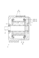
図1に示すように、回転電機としてのモータジェネレータ5は、ハウジング10、シャフト15、ロータ16およびステータ20を備える。
モータジェネレータ5は、例えば、電気自動車やハイブリッド車両等の電動車両に適用され、駆動トルクを発生する。
また、モータジェネレータ5は、駆動輪を駆動するための電動機としての機能、および、エンジンや駆動輪等から伝わる運動エネルギーによって発電する発電機としての機能、を有する。本実施形態のモータジェネレータ5は、3相ブラシレスの回転電機である。
(First embodiment)
The rotating electric machine according to the first embodiment is shown in FIGS. 1 to 11.
As shown in FIG. 1, a
The
Further, the
ハウジング10は、一対のハウジング部材11、12が接合されて形成されている。
ハウジング部材11、12は、有底筒状に形成されている。
ハウジング部材11の底部には軸受13が設けられ、ハウジング部材12の底部には軸受14が設けられている。
シャフト15は、軸受13、14を介して、ハウジング10に回転可能に支持されている。
The
The
A
The
ロータ16は、周方向に配列された複数対の磁極を有し、シャフト15に固定され、シャフト15と一体となって回転する。
ロータ16は、周方向において磁極が所定間隔で交互となるように、複数個の永久磁石を外周面に有する。永久磁石に代替して、界磁巻線を巻装した巻線界磁式等としてもよい。本実施形態では、磁極数Mは8極で、N極が4つ、S極が4つとする。
The
The
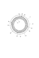
図2−図6に示すように、ステータ20は、ロータ16の径方向外側に設けられている。
また、ステータ20は、ステータコア21および巻線30を有する。
ステータコア21は、複数のコアシートが軸方向に積層されて、ハウジング10に固定されている。コアシートは、鋼板で形成されている。
また、ステータコア21は、複数のスロット22およびインシュレータ24を含む。
As shown in FIGS. 2 to 6, the
Further, the
The
The
スロット22は、等ピッチで放射状に形成され、巻線30が巻回されている。
本実施形態では、ロータ16の1極あたり、各相につきスロット倍数kのスロット22が形成されている。例えば、スロット倍数k=2の場合、ステータコア21には、8[極]×3[相]×2=48のスロット22が形成されている。
本実施形態では、スロット倍数kを2とする。
The
In the present embodiment,
In the present embodiment, the slot multiple k is 2.
1つのスロット22は、セグメントコンダクタ35の挿入部36が径方向に6本挿入可能に、形成されている。
インシュレータ24は、スロット22に設けられ、ステータ20と巻線30との間を絶縁する。
巻線30は、複数のセグメントコンダクタ35が電気的に接続されて構成されている。
One
The
The winding
図3および図4に示すように、セグメントコンダクタ35は、絶縁膜が被覆された導体をU字形状に折り曲がって形成されている。
また、セグメントコンダクタ35は、挿入部36およびターン部38を有する。
挿入部36は、互いに並行な一対となっている。
ターン部38は、挿入部36の一端を連結する。
As shown in FIGS. 3 and 4, the
Further, the
The
The
一対の挿入部36は、ステータコア21の軸方向における一方の端部である第1端部211側から、それぞれ異なるスロット22に挿入される。このとき、ターン部38が第1端部211側に突出し、第1コイルエンド31が形成される。
先端側の挿入部36は、他の挿入部36または渡り線と溶接により電気的に接続される。このとき、ステータ20の第2端部212側にて第2コイルエンド32が形成される。
2つのセグメントコンダクタ35が接続される箇所を接続部39とする。なお、セグメントコンダクタ35同士、または、セグメントコンダクタ35と渡り線とが電気的に接続される箇所の絶縁膜は適宜剥離される。
The pair of
The distal end
A portion where the two
図4および図5に示すように、4個のセグメントコンダクタ35が接続されることによって、巻線30は、ステータコア21を1周する。
図6に示すように、後述する1つの部分巻線は、12個のセグメントコンダクタ35を接続して形成される。セグメントコンダクタ35の配置および巻回方向等の詳細については後述する。
巻線30は、U相巻線40、V相巻線50およびW相巻線60を有する。本実施形態では、U相巻線40、V相巻線50およびW相巻線60が「3相の巻線」に対応する。以下適宜、「各相巻線40、50、60」という。
As shown in FIGS. 4 and 5, by connecting the four
As shown in FIG. 6, one partial winding described later is formed by connecting twelve
The winding 30 has a U-phase winding 40, a V-phase winding 50, and a W-phase winding 60. In the present embodiment, the U-phase winding 40, the V-phase winding 50, and the W-phase winding 60 correspond to “three-phase winding”. Hereinafter, each phase winding 40, 50, 60 will be referred to as appropriate.
図7に示すように、U相巻線40、V相巻線50およびW相巻線60は、n個の部分巻線に分割されている。nは2以上の整数である。
本実施形態では、n=4であり、U相巻線40、V相巻線50およびW相巻線60は、それぞれ、4つの部分巻線に分割されている。
As shown in FIG. 7, the U-phase winding 40, the V-phase winding 50, and the W-phase winding 60 are divided into n partial windings. n is an integer of 2 or more.
In this embodiment, n=4, and the U-phase winding 40, the V-phase winding 50, and the W-phase winding 60 are each divided into four partial windings.
図7および図8に示すように、U相巻線40は、第1U相部分巻線41、第2U相部分巻線42、第3U相部分巻線43および第4U相部分巻線44を有する。
U相巻線40は、波巻に構成され、U相部分巻線41−44が直列に接続されている。
U相巻線40の一端45は、第2インバータ部80に接続され、U相巻線40の他端46は、第1インバータ部70に接続される。
As shown in FIGS. 7 and 8, the U-phase winding 40 has a first U-phase partial winding 41, a second U-phase partial winding 42, a third U-phase partial winding 43 and a fourth U-phase partial winding 44. ..
The U-phase winding 40 is formed in a wave winding, and the U-phase
One
V相巻線50は、第1V相部分巻線51、第2V相部分巻線52、第3V相部分巻線53および第4V相部分巻線54を有する。
V相巻線50は、波巻に構成され、V相部分巻線51−54が直列に接続されている。
V相巻線50の一端55は、第2インバータ部80に接続され、V相巻線50の他端56は、第1インバータ部70に接続される。
The V-phase winding 50 has a first V-phase partial winding 51, a second V-phase partial winding 52, a third V-phase partial winding 53 and a fourth V-phase partial winding 54.
The V-phase winding 50 is formed in a wave winding, and the V-phase partial windings 51-54 are connected in series.
One
W相巻線60は、第1W相部分巻線61、第2W相部分巻線62、第3W相部分巻線63および第4W相部分巻線64を有する。
W相巻線60は、波巻に構成され、W相部分巻線61−64が直列に接続されている。
W相巻線60の一端65は、第2インバータ部80に接続され、W相巻線60の他端66は、第1インバータ部70に接続される。
The W-phase winding 60 has a first W-phase partial winding 61, a second W-phase partial winding 62, a third W-phase partial winding 63 and a fourth W-phase partial winding 64.
The W-phase winding 60 is formed in a wave winding, and the W-phase partial windings 61-64 are connected in series.
One
U相巻線40の一端45は、取出線47と接続され、U相巻線40の他端46は、取出線48と接続されている。
V相巻線50の一端55は、取出線57と接続され、V相巻線50の他端56は、取出線58と接続されている。
W相巻線60の一端65は、取出線67と接続され、W相巻線60の他端66は、取出線68と接続されている。
One
One
One
図1に示すように、取出線47、48、57、58、67、68は、ハウジング10の軸方向端部から取り出される。
取出線47、57、67は、スロット22の径方向内側から取り出される。
取出線48、58、68は、スロット22の径方向外側から取り出される。
なお、図1においては、煩雑になることを避けるため、取出線47、57、67および取出線48、58、68を、それぞれ1本ずつ記載した。
以下、図8等においては、U相巻線40を1つのコイルとして図示している。V相巻線
50およびW相巻線60についても同様である。
As shown in FIG. 1, the
The extraction lines 47, 57, 67 are extracted from the inside of the
The extraction lines 48, 58, 68 are extracted from the outside of the
In addition, in FIG. 1, in order to avoid complication, one
Hereinafter, in FIG. 8 and the like, the U-phase winding 40 is illustrated as one coil. The same applies to the V-phase winding 50 and the W-phase winding 60.
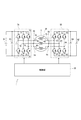
図8に示すように、電力変換システム1は、モータジェネレータ5、第1インバータ部70および第2インバータ部80を備える。
第1インバータ部70は、3相インバータであり、巻線30への通電を切り替え可能である。
また、第1インバータ部70は、6つのスイッチング素子71−76が接続されている。高電位側のスイッチング素子71と低電位側のスイッチング素子74との接続点77に、U相巻線40の他端46が接続される。高電位側のスイッチング素子72とスイッチング素子75との接続点78に、V相巻線50の他端56が接続される。高電位側のスイッチング素子73と低電位側のスイッチング素子75との接続点79に、W相巻線60の他端66が接続される。
As shown in FIG. 8, the
The
Further, the
第2インバータ部80は、3相インバータであり、巻線30への通電を切り替え可能である。
また、第2インバータ部80は、6つのスイッチング素子81−86が接続されている。高電位側のスイッチング素子81と低電位側のスイッチング素子84との接続点87には、U相巻線40の一端45が接続される。高電位側のスイッチング素子82と低電位側のスイッチング素子85との接続点88には、V相巻線50の一端55が接続される。高電位側のスイッチング素子83と低電位側のスイッチング素子86との接続点89には、W相巻線60の一端65が接続される。
The
Further, the
本実施形態では、第1インバータ部70および第2インバータ部80は、巻線30の両側に接続される。
本実施形態では、スイッチング素子71−76、81−86は、IGBTである。スイッチング素子71−76、81−86は、MOSFETまたはバイポーラトランジスタ等であってもよい。以下適宜、高電位側に接続されるスイッチング素子71−73、81−83を「上アーム素子」、低電位側に接続されるスイッチング素子74−76、84−86を「下アーム素子」という。
In the present embodiment, the
In this embodiment, the switching elements 71-76 and 81-86 are IGBTs. The switching elements 71-76, 81-86 may be MOSFETs or bipolar transistors or the like. Hereinafter, the switching elements 71-73 and 81-83 connected to the high potential side will be appropriately referred to as "upper arm element", and the switching elements 74-76 and 84-86 connected to the low potential side will be referred to as "lower arm element".
「第1電力供給源」としての第1バッテリ91は、充放電可能な直流電源であって、第1インバータ部70と接続されている。
また、第1バッテリ91は、第1インバータ部70を経由してモータジェネレータ5と電力を授受可能に設けられている。第1バッテリ91の電圧を第1電圧V1とする。
The
Further, the
「第2電力供給源」としての第2バッテリ92は、充放電可能な直流電源であって、第2インバータ部80と接続されていうr。
また、第2バッテリ92は、第2インバータ部80を経由してモータジェネレータ5と電力を授受可能に設けられている。第2バッテリ92の電圧を第2電圧V2とする。
第2電圧V2は、第1電圧V1以上に設定されている。
第1実施形態では、V1=200[V]とし、V2=600[V]とする。
The
Further, the
The second voltage V2 is set to be equal to or higher than the first voltage V1.
In the first embodiment, V1=200 [V] and V2=600 [V].
第1コンデンサ93は、第1バッテリ91と並列に接続されている。
第1コンデンサ93は、第1バッテリ91から第1インバータ部70へ供給される電流、または、第1インバータ部70から第1バッテリ91へ供給される電流を平滑化する。
第2コンデンサ94は、第2バッテリ92と並列に接続されている。
第2コンデンサ94は、第2バッテリ92から第2インバータ部80へ供給される電流、または、第2インバータ部80から第2バッテリ92へ供給される電流を平滑化する。
The
The
The
The
制御部95は、通常のコンピュータとして構成されており、内部には、CPU、ROM
、RAM、I/Oおよびこれらを接続するバスライン等が備えられる。
制御部95は、スイッチング素子71−76、81−86のオンオフを制御する制御信号を生成する。
The
, RAM, I/O and a bus line connecting them, and the like.
The
モータジェネレータ5の駆動モードについて、説明する。
図9に示すように、本実施形態では、回転数およびトルクが比較的小さい駆動領域R1において「片側駆動モード」とする。また、本実施形態では、回転数およびトルクが比較的大きい駆動領域R2において「両側駆動モード」とする。
The drive mode of the
As shown in FIG. 9, in the present embodiment, the "one side drive mode" is set in the drive region R1 in which the rotation speed and the torque are relatively small. Further, in the present embodiment, the "bilateral drive mode" is set in the drive region R2 in which the rotation speed and torque are relatively large.
片側駆動モードでは、第2インバータ部80の上アーム素子81−83を3相同時オン、下アーム素子84−86を3相同時オフにしている。
これにより、第2インバータ部80側が中性点化される。また、上アーム素子81−83を3相同時オフ、下アーム素子84−86を3相同時オンとしても、同様に第2インバータ部80側が中性点化される。
In the one-side drive mode, the upper arm elements 81-83 of the
As a result, the
また、第1インバータ部70は、電圧指令に基づく基本波と、三角波等であるキャリア波とに基づいてPWM制御される。ここで、PWM制御は、正弦波PWM制御および過変調PWM制御を含む。
正弦波PWM制御では、基本波の振幅がキャリア波の振幅以下である。
過変調PWM制御では、基本波の振幅がキャリア波の振幅より大きい。
このとき、モータジェネレータ5に印加される電圧である駆動電圧は、パルスの高さが第1電圧V1となる。
The
In the sine wave PWM control, the amplitude of the fundamental wave is equal to or less than the amplitude of the carrier wave.
In the overmodulation PWM control, the amplitude of the fundamental wave is larger than the amplitude of the carrier wave.
At this time, the drive voltage, which is the voltage applied to the
また、第1インバータ部70の上アーム素子71−73を3相同時オン、下アーム素子74−76を3相同時オフとすることで第1インバータ部70側を中性点化し、第2インバータ部80をPWM制御してもよい。上アーム素子71−73を3相同時オフ、下アーム素子74−76を3相同時オンとしても、同様に第1インバータ部70側が中性点化される。
このとき、モータジェネレータ5に印加される電圧である駆動電圧は、パルスの高さが第2電圧V2となる。
Further, the upper arm elements 71-73 of the
At this time, the drive voltage, which is the voltage applied to the
いずれか一方のインバータ部70、80を中性点化することで、スイッチング損失を低減できる。また、中性点化されるインバータ部70、80、および、3相同時オンされる素子を適宜切り替えることで、特定の素子のオン状態が継続することによる発熱や、素子間の熱損失の偏りを低減できる。
Switching loss can be reduced by making one of the
両側駆動モードでは、第1インバータ部70および第2インバータ部80は、PWM制御、または、矩形波制御される。
第1インバータ部70の駆動に係る基本波を第1基本波とし、第2インバータ部80の駆動に係る基本波を第2基本波とする。
PWM制御では、第1基本波と第2基本波とは、位相が反転されている。第1基本波と第2基本波とは、位相が180[°]ずれている。
In the double-sided drive mode, the
The fundamental wave for driving the
In the PWM control, the phases of the first fundamental wave and the second fundamental wave are inverted. The first fundamental wave and the second fundamental wave are out of phase by 180[°].
基本波の位相を反転することで、各相にてオンされる素子は、第1インバータ部70と第2インバータ部80とで上下反対となる。これにより、第1バッテリ91と第2バッテリ92とを直列に接続した状態に対応する電圧をモータジェネレータ5に印加可能である。なお、第1基本波と第2基本波との位相差は、180[°]であるが、第1バッテリ91と第2バッテリ92とを直列に接続した状態に対応する電圧を印加可能な程度のずれは許容される。
By inverting the phase of the fundamental wave, the elements that are turned on in each phase are upside down in the
両側駆動モードでは、第1インバータ部70において、U相の上アーム素子71がオン、V相およびW相の下アーム素子75、76がオンされる。同時に、第2インバータ部80において、U相の下アーム素子84がオン、V相およびW相の上アーム素子82、83がオンされる。
このとき、駆動電圧は、パルスの高さが第1電圧V1と第2電圧V2との和となる。
In the double-sided drive mode, in the
At this time, the driving voltage is such that the pulse height is the sum of the first voltage V1 and the second voltage V2.
従来、固定子鉄心のスロットに複数のセグメントコンダクタを挿入し、セグメントコンダクタを溶接等により接合することで固定子巻線を形成するセグメント接合型の電動機が知られている。特許文献1では、端子が接続される第1周回コイルと径方向で隣接するコイルを、周方向で隣接するコイルよりも中性点側のものとすることで、端子から電圧を印加した瞬間にコイルエンド部において部分放電が発生するのを抑制している。
BACKGROUND ART Conventionally, there is known a segment joint type electric motor in which a plurality of segment conductors are inserted into slots of a stator core and the segment conductors are joined by welding or the like to form a stator winding. In
特許文献1では、周回コイルの両端部が接触する。このため、両端部の電圧が高くなるシステムにおいては、両端部に印加される電圧に耐えうる絶縁被膜を形成する必要がある。
そこで、本実施形態のモータジェネレータ5は、巻線30間の最大電圧を低減可能にする。
In
Therefore, the
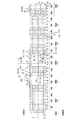
本実施形態の巻線30の詳細を図10に基づいて説明する。
図10は、スロット22に挿入されるセグメントコンダクタ35の対応する部分巻線を説明するための図である。例えば、U相スロットの「1」は、第1U相部分巻線41を構成することを意味する。
図10において、紙面左右方向がステータ20の周方向であって、紙面右から左に向かう方向が反時計回り方向、紙面左から右に向かう方向が時計回り方向とする。また、紙面上下方向がステータ20の径方向に対応し、紙面上側が径方向外側、下側が径方向内側に対応する。
The details of the winding
FIG. 10 is a diagram for explaining a corresponding partial winding of the
10, the left-right direction of the paper is the circumferential direction of the
本実施形態では、スロット倍数k=2であるので、ステータ20において、1つの磁極に対応する3[相]×2(スロット倍数)=6つのスロット22を「領域」とする。
また、本実施形態では、磁極数M=8であるので、領域数は8である。
U相巻線40の最も一端45側となる挿入部36が挿入されるスロット22を含む領域を「領域A」とする。また、領域Aから時計回りに、領域B、領域C・・・とし、領域Aから反時計回りに、領域H、領域G・・・とする。
In the present embodiment, since the slot multiple k=2, 3 [phases]×2 (slot multiple)=6
Further, in the present embodiment, the number of magnetic poles M=8, so the number of regions is eight.
The region including the
各領域内におけるスロット番号を時計回り方向に1〜6とする。
各スロット22内における位置を表す周番号を、径方向外側から1〜6とする。
図中において、スロット番号および周番号は、丸印を付した番号で記載する。
以下、挿入部36が挿入される箇所を、領域、スロット番号、周番号の順で表すこととし、具体的には、U相巻線40の最も一端45となる挿入部36が挿入される箇所を「A21」と表す。
また、図中において、U相巻線40を構成するセグメントコンダクタ35が挿入されるスロット22を太線で記載する。また、V相巻線50およびW相巻線60を構成するセグメントコンダクタ35が挿入されるスロット22を細線で記載する。
The slot numbers in each area are set to 1 to 6 in the clockwise direction.
The circumferential numbers representing the positions in each
In the figure, the slot number and the peripheral number are described by numbers with circles.
Hereinafter, the place where the
Further, in the figure, the
図10において、セグメントコンダクタ35を実線で示し、渡り線を破線で示す。
丸印で記載した箇所は、U相巻線40の一端45または他端46、V相巻線50の一端55または他端56、および、W相巻線60の一端65または他端66、であることを意味する。
三角印で記載した箇所は、渡り線にて接続される箇所であることを意味する。
In FIG. 10, the
The circled portions are one
The points marked with triangles mean that they are connected by crossovers.
各U相部分巻線41−44の一端45側の端部をS1−S4とする。
各U相部分巻線41−44の他端46側の端部をE1−E4とする。
始端S1がU相巻線40の一端45に対応し、終端E4がU相巻線40の他端46に対応する。
The ends of the U-phase partial windings 41-44 on the one
The ends of the U-phase partial windings 41-44 on the
The starting end S1 corresponds to one
各V相部分巻線51−54の一端55側の端部をS5−S8とする。
各V相部分巻線51−54の他端56側の端部をE5−E8とする。
始端S5がV相巻線50の一端55に対応し、終端E8がV相巻線50の他端56に対応する。
The end portions of the respective V-phase partial windings 51-54 on the one
The end portions of the respective V-phase partial windings 51-54 on the
The start end S5 corresponds to one
各W相部分巻線61−64の一端65側の端部をS9−S12とする。
各W相部分巻線61−64の他端66側の端部をE9−E12とする。
始端S9がW相巻線60の一端65に対応し、終端E12がW相巻線60の他端66に対応する。
The end portions of the respective W-phase partial windings 61-64 on the one
The end portions of the W-phase partial windings 61-64 on the
The start end S9 corresponds to one
図10に示すように、領域Aにおいて、A1スロットに、第2U相部分巻線42および第4U相部分巻線44を構成するセグメントコンダクタ35が挿入される。
A2スロットに、第1U相部分巻線41および第3U相部分巻線43を構成するセグメントコンダクタ35が挿入される。
As shown in FIG. 10, in the region A, the
The
A3スロットに、第2V相部分巻線52および第4V相部分巻線54を構成するセグメントコンダクタ35が挿入される。
A4スロットに、第1V相部分巻線51および第3V相部分巻線53を構成するセグメントコンダクタ35が挿入される。
The
The
A5スロットに、第1W相部分巻線61および第3W相部分巻線63を構成するセグメントコンダクタ35が挿入される。
A6スロットに、第2W相部分巻線62および第4W相部分巻線64を構成するセグメントコンダクタ35が挿入される。
他の領域においても同様である。
The
The
The same applies to other areas.
U相巻線40の最も一端45側となるセグメントコンダクタ35は、一方の挿入部36がA21に挿入され、他方の挿入部36がH22に挿入されるように、スロット22に挿入される。
U相巻線40の一端45側から2番目のセグメントコンダクタ35は、一方の挿入部36がG21に挿入され、他方の挿入部36がF22に挿入されるように、スロット22に挿入される。
The
The
第1実施形態では、挿入部36は、隣接する磁極に対応する領域のスロット番号が同じであって径方向における位置が1つずれた箇所に挿入される。
また、U相巻線40の最も一端45側のセグメントコンダクタ35と2番目のセグメントコンダクタ35とは、B22に挿入された挿入部36とC21に挿入された挿入部36とを溶接等により接続することで、接続される。
第1実施形態では、異なるセグメントコンダクタ35を電気的に接続していくことで、巻線30を構成する。
以下、挿入部36が挿入されるスロット位置および巻回方向を説明する。
In the first embodiment, the
Further, the
In the first embodiment, the winding 30 is configured by electrically connecting
Hereinafter, the slot position in which the
第1U相部分巻線41は、A21、H22、G21、F22、E21、D22、C21、B22、A23、H24、・・・、C23、B24、A25、H26、・・・、C25、B26の順に、12個のセグメントコンダクタ35が接続されている。
第1U相部分巻線41は、反時計回りに巻回され、径方向外側から内側に向かって、巻回されている。
The first U-phase partial winding 41 includes A21, H22, G21, F22, E21, D22, C21, B22, A23, H24,..., C23, B24, A25, H26,..., C25, B26 in this order. , 12
The first U-phase partial winding 41 is wound counterclockwise, and is wound from the radially outer side toward the inner side.
第2U相部分巻線42は、A16、H15、G16、F15、E16、D15、C16、B15、A14、H13、・・・、C14、B13、A12、H11、・・・、C12、B11の順に、12個のセグメントコンダクタ35が接続されている。
第2U相部分巻線42は、反時計回りに巻回され、径方向内側から外側に向かって、巻回されている。
The second U-phase partial winding 42 includes A16, H15, G16, F15, E16, D15, C16, B15, A14, H13,..., C14, B13, A12, H11,..., C12, B11 in this order. , 12
The second U-phase partial winding 42 is wound counterclockwise, and is wound from the radially inner side toward the outer side.
第3U相部分巻線43は、A26、H25、G26、F25、E26、D25、C26、B25、A24、H23、・・・、C24、B23、A22、H21、・・・、C22、B21の順に、12個のセグメントコンダクタ35が接続されている。
第3U相部分巻線43は、反時計回りに巻回され、径方向内側から外側に向かって、巻回されている。
The third U-phase partial winding 43 includes A26, H25, G26, F25, E26, D25, C26, B25, A24, H23,..., C24, B23, A22, H21,..., C22, B21 in this order. , 12
The third U-phase partial winding 43 is wound counterclockwise, and is wound from the radially inner side toward the outer side.
第4U相部分巻線44は、A11、H12、G11、F12、E11、D12、C11、B12、A13、H14、・・・、C13、B14、A15、H16、・・・、C15、B16の順に、12個のセグメントコンダクタ35が接続されている。
第4U相部分巻線44は、反時計回りに巻回され、径方向外側から内側に向かって、巻回されている。
The fourth U-phase partial winding 44 includes A11, H12, G11, F12, E11, D12, C11, B12, A13, H14,..., C13, B14, A15, H16,..., C15, B16 in this order. , 12
The fourth U-phase partial winding 44 is wound counterclockwise, and is wound from the radially outer side toward the inner side.
第1U相部分巻線41の終端E1と、第2U相部分巻線42の始端S2とは、渡り線W11により接続されている。第2U相部分巻線42の終端E2と、第3U相部分巻線43の始端S3とは、渡り線W12により接続されている。第3U相部分巻線43の終端E3と、第4U相部分巻線44の始端S4とは、渡り線W13により接続されている。 The terminal end E1 of the first U-phase partial winding 41 and the starting end S2 of the second U-phase partial winding 42 are connected by a crossover W11. The terminal end E2 of the second U-phase partial winding 42 and the starting end S3 of the third U-phase partial winding 43 are connected by a crossover W12. The terminal end E3 of the third U-phase partial winding 43 and the starting end S4 of the fourth U-phase partial winding 44 are connected by a crossover W13.
第1V相部分巻線51は、D43、C44、B43、A44、H43、G44、F43、E44、D45、C46、・・・、F45、E46、D41、C42、・・・、F41、E42の順に、12個のセグメントコンダクタ35が接続される。
第1V相部分巻線51は、反時計回りに巻回されている。
The first V-phase partial winding 51 includes D43, C44, B43, A44, H43, G44, F43, E44, D45, C46,..., F45, E46, D41, C42,..., F41, E42 in this order. , 12
The first V-phase partial winding 51 is wound counterclockwise.
第2V相部分巻線52は、D34、C33、B34、A33、H34、G33、F34、E33、D32、C31、・・・、F32、E31、D36、C35、・・・、F36、E35の順に、12個のセグメントコンダクタ35が接続される。
第2V相部分巻線52は、反時計回りに巻回されている。
The second V-phase partial winding 52 includes D34, C33, B34, A33, H34, G33, F34, E33, D32, C31,..., F32, E31, D36, C35,..., F36, E35 in this order. , 12
The second V-phase partial winding 52 is wound counterclockwise.
第3V相部分巻線53は、D44、C43、B44、A43、H44、G43、F44、E43、D42、C41、・・・、F42、E41、D46、C45、・・・、F46、E45の順に、12個のセグメントコンダクタ35が接続される。
第3V相部分巻線53は、反時計回りに巻回されている。
The third V-phase partial winding 53 includes D44, C43, B44, A43, H44, G43, F44, E43, D42, C41,..., F42, E41, D46, C45,..., F46, E45 in this order. , 12
The third V-phase partial winding 53 is wound counterclockwise.
第4V相部分巻線54は、D33、C34、B33、A34、H33、G34、F33、E34、D35、C36、・・・、F35、E36、D31、C32、・・・、F31、E32の順に、12個のセグメントコンダクタ35が接続される。
第4V相部分巻線54は、反時計回りに巻回されている。
The fourth V-phase partial winding 54 includes D33, C34, B33, A34, H33, G34, F33, E34, D35, C36,..., F35, E36, D31, C32,..., F31, E32 in this order. , 12
The fourth V-phase partial winding 54 is wound counterclockwise.
第1V相部分巻線51の終端E5と、第2V相部分巻線52の始端S6とは、渡り線により接続されている。第2V相部分巻線52の終端E6と、第3V相部分巻線53の始端S7とは、渡り線により接続されている。第3V相部分巻線53の終端E7と、第4V相部分巻線54の始端S8とは、渡り線Wより接続されている。 The terminal end E5 of the first V-phase partial winding 51 and the starting end S6 of the second V-phase partial winding 52 are connected by a crossover wire. The terminal end E6 of the second V-phase partial winding 52 and the starting end S7 of the third V-phase partial winding 53 are connected by a crossover wire. The terminal end E7 of the third V-phase partial winding 53 and the starting end S8 of the fourth V-phase partial winding 54 are connected by a crossover W.
第1W相部分巻線61は、A56、H55、G56、F55、E56、D55、C56、B55、A54、H53、・・・、C54、B53、A52、H51、・・・、C52、B51の順に、12個のセグメントコンダクタ35が接続されている。
第1W相部分巻線61は、反時計回りに径方向外側から内側に巻回されている。
The first W-phase partial winding 61 includes A56, H55, G56, F55, E56, D55, C56, B55, A54, H53,..., C54, B53, A52, H51,..., C52, B51 in this order. , 12
The first W-phase partial winding 61 is wound counterclockwise from the outer side to the inner side in the radial direction.
第2W相部分巻線62は、A66、H65、G66、F65、E66、D65、C66、B65、A64、H63、・・・、C64、B63、A62、H61、・・・、C62、B61の順に、12個のセグメントコンダクタ35が接続されている。
第2W相部分巻線62は、反時計回りに径方向内側から外側に巻回されている。
The second W-phase partial winding 62 includes A66, H65, G66, F65, E66, D65, C66, B65, A64, H63,..., C64, B63, A62, H61,..., C62, B61 in this order. , 12
The second W-phase partial winding 62 is wound counterclockwise from the inner side to the outer side in the radial direction.
第3W相部分巻線63は、A51、H52、G51、F52、E51、D52、C51、B52、A53、H54、・・・、C53、B54、A55、H56、・・・、C55、B56の順に、12個のセグメントコンダクタ35が接続されている。
第3W相部分巻線63は、反時計回りに径方向外側から内側に巻回されている。
The third W-phase partial winding 63 includes A51, H52, G51, F52, E51, D52, C51, B52, A53, H54,..., C53, B54, A55, H56,..., C55, B56 in this order. , 12
The third W-phase partial winding 63 is wound counterclockwise from the outer side to the inner side in the radial direction.
第4W相部分巻線64は、A61、H62、G61、F62、E61、D62、C61、B62、A63、H64、・・・、C63、B64、A65、H66、・・・、C65、B66の順に、12個のセグメントコンダクタ35が接続されている。
第4W相部分巻線64は、反時計回りに径方向外側から内側に巻回されている。
The fourth W-phase partial winding 64 includes A61, H62, G61, F62, E61, D62, C61, B62, A63, H64,..., C63, B64, A65, H66,..., C65, B66 in this order. , 12
The fourth W-phase partial winding 64 is wound counterclockwise from the outer side to the inner side in the radial direction.
第1W相部分巻線61の終端E9と、第2W相部分巻線62の始端S10とは、渡り線により接続される。第2W相部分巻線62の終端E10と、第3W相部分巻線63の始端S11とは、渡り線により接続される。第3W相部分巻線63の終端E11と、第4W相部分巻線64の始端S12とは、渡り線により接続される。図中において、煩雑さを避けるため、V相巻線50およびW相巻線60の渡り線を省略する。また、第1実施形態の巻回方向は、反時計回りの一方向に巻回されている。なお、巻回方向は、反時計回りに限らず、時計回りとしてもよい。 The terminal end E9 of the first W-phase partial winding 61 and the starting end S10 of the second W-phase partial winding 62 are connected by a crossover wire. The terminal end E10 of the second W-phase partial winding 62 and the starting terminal S11 of the third W-phase partial winding 63 are connected by a crossover wire. The terminal E11 of the third W-phase partial winding 63 and the starting end S12 of the fourth W-phase partial winding 64 are connected by a crossover wire. In the figure, the crossover wires of the V-phase winding 50 and the W-phase winding 60 are omitted to avoid complexity. The winding direction of the first embodiment is one counterclockwise winding direction. The winding direction is not limited to the counterclockwise direction and may be the clockwise direction.
第1実施形態では、U相巻線40の一端45に対応する始端S1がスロット22をステータ20の径方向に2分割する分割線Pよりも径方向外側に設けられている。
また、W相巻線60の一端65に対応する始端S9が分割線Pよりも径方向内側に設けられている。
さらに、V相巻線50の一端55に対応する始端S5が、少なくとも1つのスロット22を挟んで、ステータ20の径方向に対して、U相巻線40の一端45とW相巻線60の一端65との間に設けられている。
In the first embodiment, the starting end S1 corresponding to the one
Further, a start end S9 corresponding to one
Further, the starting end S5 corresponding to the one
ここで、両側駆動モータにおいて、スイッチング状態のときの電圧分布を図11に示す。図11において、第1インバータ部70、第2インバータ部80、第1コンデンサ93第2コンデンサ94および制御部95の記載を省略し、巻線30、930の各箇所における電位、および、巻線30、930が絶縁被膜を介して接触する箇所の電位を破線で示す。
Here, in the double-sided drive motor, the voltage distribution in the switching state is shown in FIG. In FIG. 11, the description of the
図11(b)に示すように、参考例としての電力変換システム9は、バッテリ910、920および巻線930を備える。バッテリ910の電圧を200Vとし、バッテリ920の電圧を600Vとし、バッテリ920の電圧は、バッテリ910の電圧よりも高く設定されている。
バッテリ910は、巻線930の一方側に設けられており、バッテリ920は、巻線930の他方側に設けられている。
As shown in FIG. 11B, the
The
巻線930では、U相巻線940、V相巻線950およびW相巻線960の一側を接続して中性点970としている。また、各巻線930の一端は、接触している。
電力変換システム9において、バッテリ910、920の電圧を巻線930に印加する場合、電力変換システム9における最大電圧が相関電圧Vi(参考例では600V)となる。このため、巻線930に、サージ電圧分を考慮した絶縁皮膜を設ける必要がある。
In the winding 930, one side of the U-phase winding 940, the V-phase winding 950, and the W-phase winding 960 is connected to form a
When the voltages of the
一方、本実施形態の電力変換システム1においで、巻線30の耐圧を下げることができ、絶縁皮膜を薄膜化できる。
本実施形態の電力変換システム1において、第1バッテリ91の負極側を電位0[V]とすると、スイッチング状態のときのDC成分の電圧分布は、図11(a)に示すようになる。
On the other hand, in the
In the
他の2相とオンされる素子の上下が異なる1相の両端電圧Vbおよび相関電圧Viは、以下の式(1)、(2)で表される。両側駆動モードの場合における最大電圧箇所は、U相巻線40、V相巻線50またはW相巻線60の両端電圧Vbとなる。本実施形態では、両端電圧Vbは、約533Vである。
また、図11に示すように、各相において、接触可能性のある箇所の電圧である相内電圧Vcは、式(3)で表される。なお、式(3)のnは、各相巻線40、50、60の分割数である。本実施形態では、分割数n=4である。
Vb=(V1+V2)×(2/3) ・・・(1)
Vi=(V1+V2)/2 ・・・(2)
Vc=Vb×(n−1)/n ・・・(3)
The voltage Vb between both ends and the correlation voltage Vi of one phase which is different from the other two phases in the turned-on element are expressed by the following equations (1) and (2). The maximum voltage location in the double-sided drive mode is the voltage Vb across the U-phase winding 40, the V-phase winding 50, or the W-phase winding 60. In this embodiment, the voltage Vb between both ends is about 533V.
In addition, as shown in FIG. 11, in each phase, the in-phase voltage Vc, which is the voltage at the point where there is a possibility of contact, is expressed by equation (3). In addition, n of Formula (3) is the division number of each phase winding 40, 50, 60. In the present embodiment, the number of divisions n=4.
Vb=(V1+V2)×(2/3) (1)
Vi=(V1+V2)/2 (2)
Vc=Vb*(n-1)/n (3)
第1実施形態では、U相巻線40の一端45が分割線Pよりも径方向外側に設けられており、W相巻線60の一端65が分割線Pよりも径方向内側に設けられている。
また、V相巻線50の一端55が、少なくとも1つのスロット22を挟んで、U相巻線40の一端45とW相巻線60の一端65との間に設けられている。
これにより、U相巻線40の一端45、V相巻線50の一端55およびW相巻線60の一端65は確実に非接触となる。
In the first embodiment, one
Further, one
This ensures that one
第1U相部分巻線41の中間点をU相中間点Huとする。
中間点Huは、分割数n=4を2倍した数の8でU相巻線40を等分割した箇所である。
第1W相部分巻線61の中間点をW相中間点Hwとする。
中間点Hwは、分割数n=4を2倍した数の8でW相巻線60を等分割した箇所である。
このとき、U相中間点HuとV相巻線50の一端55が接触する箇所が最大電圧箇所となる。また、W相中間点HwとV相巻線50の一端55が接触する箇所が最大電圧箇所となる。この最大電圧箇所の電圧は、533Vである。
An intermediate point of the first U-phase partial winding 41 is a U-phase intermediate point Hu.
The midpoint Hu is a location where the U-phase winding 40 is equally divided by 8 which is twice the division number n=4.
The midpoint of the first W-phase partial winding 61 is defined as the W-phase midpoint Hw.
The midpoint Hw is a location where the W-phase winding 60 is equally divided by 8 which is twice the number of divisions n=4.
At this time, the point where the U-phase intermediate point Hu and the one
第1実施形態では、各相巻線40、50、60の一端45、55、65が非接触になることによって、参考例の電力変換システム9と比較して、モータジェネレータ5内における接触箇所の最大電圧を低減可能である。これにより、巻線30の絶縁被膜を薄膜化できる。
なお、特許請求の範囲において、「第1巻線」は、U相巻線40に相当し、「第2巻線」は、W相巻線60に相当し、「第3巻線」は、V相巻線50に相当する。
In the first embodiment, the ends 45, 55, 65 of the
In the claims, the "first winding" corresponds to the U-phase winding 40, the "second winding" corresponds to the W-phase winding 60, and the "third winding" is It corresponds to the V-phase winding 50.
(第2実施形態)
第2実施形態では、各相巻線の一端の配置および巻回方向が異なる点を除き、第1実施形態と同様である。
第2実施形態では、U相巻線40、V相巻線50およびW相巻線60は、重ね巻にて、構成されている。
以下、図12を参照して、第2実施形態における挿入部36が挿入されるスロット位置および巻回方向を説明する。
(Second embodiment)
The second embodiment is the same as the first embodiment except that the arrangement of one end of each phase winding and the winding direction are different.
In the second embodiment, the U-phase winding 40, the V-phase winding 50 and the W-phase winding 60 are formed by overlapping windings.
Hereinafter, with reference to FIG. 12, the slot position in which the
第1U相部分巻線41は、A21、H22、A23、H24、A25、H26、G21、F22、G23、F24、G25、F26、・・・、C21、B22、C23、B24、C25、B26の順に、セグメントコンダクタ35が接続されている。
第1U相部分巻線41は、反時計回りの順番で、径方向外側から内側に巻回されている。
The first U-phase partial winding 41 includes A21, H22, A23, H24, A25, H26, G21, F22, G23, F24, G25, F26,..., C21, B22, C23, B24, C25, B26 in this order. ,
The first U-phase partial winding 41 is wound in the counterclockwise order from the outer side to the inner side in the radial direction.
第2U相部分巻線42は、A16、B15、A14、B13、A12、B11、C16、D15、C14、D13、C12、D11、・・・、G16、H15、G14、H13、G12、H11の順に、セグメントコンダクタ35が接続されている。
第2U相部分巻線42は、時計回りの順番で、径方向内側から外側に巻回されている。
The second U-phase partial winding 42 includes A16, B15, A14, B13, A12, B11, C16, D15, C14, D13, C12, D11,..., G16, H15, G14, H13, G12, H11 in this order. ,
The second U-phase partial winding 42 is wound in the clockwise direction from the inner side to the outer side in the radial direction.
第3U相部分巻線43は、A26、B25、A24、B23、A22、B21、C26、D25、C24、D23、C22、D21、・・・、G26、H25、G24、H23、G22、H21の順にセグメントコンダクタ35が接続されている。
第3U相部分巻線43は、時計回りの順番で、径方向内側から外側に巻回されている。
The third U-phase partial winding 43 includes A26, B25, A24, B23, A22, B21, C26, D25, C24, D23, C22, D21,..., G26, H25, G24, H23, G22, H21 in this order. The
The third U-phase partial winding 43 is wound clockwise from the inner side to the outer side in the radial direction.
第4U相部分巻線44は、A11、H12、A13、H14、A15、H16、G11、F12、G13、F14、G15、F16、・・・、C11、B12、C13、B14、C15、B16の順に、セグメントコンダクタ35が接続されている。
第4U相部分巻線44は、反時計回りの順番で、径方向外側から内側に巻回されている。
The fourth U-phase partial winding 44 includes A11, H12, A13, H14, A15, H16, G11, F12, G13, F14, G15, F16,..., C11, B12, C13, B14, C15, B16 in this order. ,
The fourth U-phase partial winding 44 is wound in the counterclockwise order from the outer side to the inner side in the radial direction.
第1U相部分巻線41の終端E1と、第2U相部分巻線42の始端S2とは、渡り線W11により接続されている。第2U相部分巻線42の終端E2と、第3U相部分巻線43の始端S3とは、渡り線W12により接続されている。第3U相部分巻線43の終端E3と、第4U相部分巻線44の始端S4とは、渡り線W13により接続されている。 The terminal end E1 of the first U-phase partial winding 41 and the starting end S2 of the second U-phase partial winding 42 are connected by a crossover W11. The terminal end E2 of the second U-phase partial winding 42 and the starting end S3 of the third U-phase partial winding 43 are connected by a crossover W12. The terminal end E3 of the third U-phase partial winding 43 and the starting end S4 of the fourth U-phase partial winding 44 are connected by a crossover W13.
第1V相部分巻線51は、D41、C42、D43、C44、D45、C46、B41、A42、B43、A44、B45、A46、・・・、F41、E42、F43、E44、F45、E46の順に、12個のセグメントコンダクタ35が接続される。
第1V相部分巻線51は、反時計回りの順番で、径方向外側から内側に巻回されている。
The first V-phase partial winding 51 includes D41, C42, D43, C44, D45, C46, B41, A42, B43, A44, B45, A46,..., F41, E42, F43, E44, F45, E46 in this order. , 12
The first V-phase partial winding 51 is wound in the counterclockwise order from the outer side to the inner side in the radial direction.
第2V相部分巻線52は、D36、C35、D34、C33、D32、C31、B36、A35、B34、A33、B32、A31、・・・、F36、E35、F34、E33、F32、E31の順に、12個のセグメントコンダクタ35が接続される。
第2V相部分巻線52は、時計回りの順番で、径方向内側から外側に巻回されている。
The second V-phase partial winding 52 is in the order of D36, C35, D34, C33, D32, C31, B36, A35, B34, A33, B32, A31,..., F36, E35, F34, E33, F32, E31. , 12
The second V-phase partial winding 52 is wound in the clockwise direction from the inner side to the outer side in the radial direction.
第3V相部分巻線53は、D46、C45、D44、C43、D42、C41、B46、A45、B44、A43、B42、A41、・・・、F46、E45、F44、E43、F42、E41の順に、の順に12個のセグメントコンダクタ35が接続される。
第3V相部分巻線53は、時計回りの順番で、に径方向内側から外側に巻回されている。
The third V-phase partial winding 53 includes D46, C45, D44, C43, D42, C41, B46, A45, B44, A43, B42, A41,..., F46, E45, F44, E43, F42, E41 in this order. , And 12
The third V-phase partial winding 53 is wound clockwise from the inner side to the outer side in the radial direction.
第4V相部分巻線54は、D31、C32、D33、C34、D35、C36、B31、A32、B33、A34、B35、A36、・・・、F31、E32、F33、E34、F35、E36の順に、12個のセグメントコンダクタ35が接続される。
第4V相部分巻線54は、反時計回りの順番で、径方向外側から内側に巻回されている。
The fourth V-phase partial winding 54 is in the order of D31, C32, D33, C34, D35, C36, B31, A32, B33, A34, B35, A36,..., F31, E32, F33, E34, F35, E36. , 12
The fourth V-phase partial winding 54 is wound in the counterclockwise order from the outer side to the inner side in the radial direction.
第1V相部分巻線51の終端E5と、第2V相部分巻線52の始端S6とは、渡り線により接続されている。第2V相部分巻線52の終端E6と、第3V相部分巻線53の始端S7とは、渡り線により接続されている。第3V相部分巻線53の終端E7と、第4V相部分巻線54の始端S8とは、渡り線により接続されている。 The terminal end E5 of the first V-phase partial winding 51 and the starting end S6 of the second V-phase partial winding 52 are connected by a crossover wire. The terminal end E6 of the second V-phase partial winding 52 and the starting end S7 of the third V-phase partial winding 53 are connected by a crossover wire. The terminal end E7 of the third V-phase partial winding 53 and the starting end S8 of the fourth V-phase partial winding 54 are connected by a crossover wire.
第1W相部分巻線61は、A56、B55、A54、B53、A52、B51、C56、D55、C54、D53、C52、D51、・・・、G56、H55、G54、H53、G52、H51の順に、セグメントコンダクタ35が接続されている。
第1W相部分巻線61は、時計回りの順番で、径方向内側から外側に巻回されている。
The first W-phase partial winding 61 includes A56, B55, A54, B53, A52, B51, C56, D55, C54, D53, C52, D51,..., G56, H55, G54, H53, G52, H51 in this order. ,
The first W-phase partial winding 61 is wound in the clockwise order from the radially inner side to the outer side.
第2W相部分巻線62は、A66、B65、A64、B63、A62、B61、C66、D65、C64、D63、C62、D61、・・・、G66、H65、G64、H63、G62、H61の順に、セグメントコンダクタ35が接続されている。
第2W相部分巻線62は、時計回りの順番で、径方向内側から外側に巻回されている。
The second W-phase partial winding 62 includes A66, B65, A64, B63, A62, B61, C66, D65, C64, D63, C62, D61,..., G66, H65, G64, H63, G62, H61 in this order. ,
The second W-phase partial winding 62 is wound clockwise from the inner side to the outer side in the radial direction.
第3W相部分巻線63は、A51、H52、A53、H54、A55、H56、G51、F52、G53、F54、G55、F56、・・・、C51、B52、C53、B54、C55、B56の順に、セグメントコンダクタ35が接続されている。
第3W相部分巻線63は、反時計回りの順番で、径方向外側から内側に巻回されている。
The third W-phase partial winding 63 includes A51, H52, A53, H54, A55, H56, G51, F52, G53, F54, G55, F56,..., C51, B52, C53, B54, C55, B56 in this order. ,
The third W-phase partial winding 63 is wound from the outer side to the inner side in the radial direction in the counterclockwise order.
第4W相部分巻線64は、A61、H62、A63、H64、A65、H66、G51、F62、G63、F64、G65、F66、・・・、C61、B62、C63、B64、C65、B66の順に、セグメントコンダクタ35が接続されている。
第4W相部分巻線64は、反時計回りの順番で、径方向外側から内側に巻回されている。
The fourth W-phase partial winding 64 includes A61, H62, A63, H64, A65, H66, G51, F62, G63, F64, G65, F66,..., C61, B62, C63, B64, C65, B66 in this order. ,
The fourth W-phase partial winding 64 is wound from the outer side to the inner side in the radial direction in the counterclockwise order.
第1W相部分巻線61の終端E9と、第2W相部分巻線62の始端S10とは、渡り線により接続されている。第2W相部分巻線62の終端E10と、第3W相部分巻線63の始端S11とは、渡り線により接続されている。第3W相部分巻線63の終端E11と、第4W相部分巻線64の始端S12とは、渡り線により接続されている。 The terminal end E9 of the first W-phase partial winding 61 and the starting end S10 of the second W-phase partial winding 62 are connected by a crossover wire. The end E10 of the second W-phase partial winding 62 and the start end S11 of the third W-phase partial winding 63 are connected by a crossover wire. The terminal E11 of the third W-phase partial winding 63 and the starting end S12 of the fourth W-phase partial winding 64 are connected by a crossover wire.
スロット22をステータ20の周方向に2分割する線を分割線Qとする。
第2実施形態では、U相巻線40の一端45に対応する始端S1が分割線Qよりも一方側に設けられている。
また、W相巻線60の一端65に対応する始端S9が分割線Qよりも他方側に設けられている。
さらに、V相巻線50の一端55に対応する始端S5が、ステータ20の周方向において、U相巻線40の一端45とW相巻線60の一端65との間に設けられている。
A line that divides the
In the second embodiment, the starting end S1 corresponding to the one
A start end S9 corresponding to one
Further, a start end S5 corresponding to one
図13に示すように、ステータコア21の中心をOとする。中心OからU相巻線40の一端45までの線をU相仮想線Iuとする。中心OからV相巻線50の一端55までの線をV相仮想線Ivとする。中心OからW相巻線60の一端65までの線をW相仮想線Iwとする。
U相仮想線IuとV相仮想線Ivとのなす角度を第1角度θ1[°]とする。W相仮想線IwとV相仮想線Ivとのなす角度を第2角度θ2[°]とする。
As shown in FIG. 13, the center of the
The angle formed by the U-phase virtual line Iu and the V-phase virtual line Iv is defined as a first angle θ1 [°]. The angle formed by the W-phase virtual line Iw and the V-phase virtual line Iv is defined as a second angle θ2 [°].
第1角度θ1が以下関係式(4)を満たすように、設定されている。または、第2角度θ2が以下関係式(5)を満たすように、設定されている。第2実施形態においても、第1実施形態と同様の効果を奏する。
θ1≧360÷M×2 ・・・(4)
θ2≧360÷M×2 ・・・(5)
The first angle θ1 is set so as to satisfy the following relational expression (4). Alternatively, the second angle θ2 is set so as to satisfy the following relational expression (5). Also in the second embodiment, the same effect as that of the first embodiment is obtained.
θ1≧360÷M×2 (4)
θ2≧360÷M×2 (5)
(その他の実施形態)
(i)図14に示すように、第2インバータ部80と第2バッテリ92との間に昇圧コンバータ96を設けて、第2電圧V2が第1電圧V1よりも大きくしてもよい。
昇圧コンバータ96は、リアクトル97、昇圧部98および平滑コンデンサ99を含む。
昇圧コンバータ96は、第2電圧V2を昇圧し、昇圧電圧Vsを生成する。生成された昇圧電圧Vsが第2インバータ部80に出力される。
(Other embodiments)
(I) As shown in FIG. 14, a
リアクトル97は、電流の変化に伴って発生する誘起電圧による電気エネルギーを蓄積および放出可能である。
昇圧部98は、直列に接続された2つのスイッチング素子981、982および各スイッチング素子981、982に対して並列に接続された還流ダイオードを含む。
平滑コンデンサ99は、昇圧コンバータ96および第2インバータ部80の間に、第2インバータ部80と並列に接続され、昇圧電圧Vsの変動を平滑する。
The
The
The smoothing
(ii)本実施形態では、各相巻線は、4個の部分巻線から構成されている。各相巻線を1つの巻線により構成してもよいし、複数の部分巻線から構成してもよい。
(iii)本実施形態では、磁極数Mが8、スロット倍数kが2であって、スロット数が48である。磁極数Mおよびスロット倍数kは、これに限らずいくつとしてもよい。また、スロット数は、磁極数Mおよびスロット倍数kに応じ、適宜設定可能である。
(Ii) In this embodiment, each phase winding is composed of four partial windings. Each phase winding may be formed of one winding or a plurality of partial windings.
(Iii) In this embodiment, the number of magnetic poles M is 8, the slot multiple k is 2, and the number of slots is 48. The number of magnetic poles M and the multiple of slots k are not limited to this, and may be any number. The number of slots can be set as appropriate according to the number of magnetic poles M and the multiple k of slots.
(iv)1つのスロットに挿入されるセグメントコンダクタ数は6または8である。1つのスロットに挿入されるセグメントコンダクタ数は、6または8に限らず、いくつとしてもよい。また、セグメントコンダクタに替えて、一般的な断面が円形状である導線を巻回することで巻線を構成してもよい。
(v)各相巻線の一端および他端は、ハウジングの軸方向端部から取り出される。各相巻線の一端または他端の少なくとも一方は、ハウジングの軸方向端部以外の箇所からハウジングの外部に取り出してもよい。
(Iv) The number of segment conductors inserted in one slot is 6 or 8. The number of segment conductors inserted in one slot is not limited to 6 or 8, and may be any number. Further, instead of the segment conductor, a winding may be formed by winding a conductor wire having a generally circular cross section.
(V) One end and the other end of each phase winding are taken out from the axial end of the housing. At least one of one end or the other end of each phase winding may be taken out of the housing from a position other than the axial end of the housing.
(vi)第1インバータ部および第2インバータ部は、PWM制御あるいは矩形波制御により制御される。第1インバータ部および第2インバータ部の制御方法は、限定されない。
(vii)回転電機は、例えば、1電源1インバータのシステム等のシステムに適用してもよい。
(Vi) The first inverter unit and the second inverter unit are controlled by PWM control or rectangular wave control. The control method of the first inverter unit and the second inverter unit is not limited.
(Vii) The rotating electric machine may be applied to a system such as a system of one power source and one inverter.
(viii)電力変換システムは、電動車両に適用される。電動車両の主機以外の車両補機や他の装置に電力変換システムを適用してもよい。
(ix)第1電力供給源または第2電力供給源の一方を電気二重層キャパシタやリチウムイオンキャパシタ等により構成してもよい。
以上、本発明はこのような実施形態に限定されるものではなく、発明の趣旨を逸脱しない範囲において、種々の形態で実施することができる。
(Viii) The power conversion system is applied to an electric vehicle. The power conversion system may be applied to vehicle accessories other than the main engine of the electric vehicle or other devices.
(Ix) One of the first power supply source and the second power supply source may be configured by an electric double layer capacitor, a lithium ion capacitor, or the like.
As described above, the present invention is not limited to such an embodiment, and can be implemented in various forms without departing from the spirit of the invention.
10 ・・・ハウジング、
15 ・・・シャフト、
16 ・・・ロータ、
20 ・・・ステータ、
21 ・・・ステータコア、
22 ・・・スロット、
30 ・・・巻線、
40 ・・・U相巻線(第1巻線)
45 ・・・U相巻線の一端、
50 ・・・V相巻線(第3巻線)
55 ・・・V相巻線の一端、
60 ・・・W相巻線(第2巻線)
65 ・・・W相巻線の一端。
P ・・・分割線、
Q ・・・分割線。
10... Housing,
15... Shaft,
16 ... rotor,
20... Stator
21 ... Stator core,
22 ... Slot,
30... Winding,
40 ... U-phase winding (first winding)
45 ... One end of U-phase winding,
50 ... V-phase winding (third winding)
55 ... One end of the V-phase winding,
60 ... W-phase winding (second winding)
65... One end of the W-phase winding.
P: dividing line,
Q: Dividing line.
Claims (8)
前記ハウジングに回転可能に支持されるシャフト(15)と、
周方向に配列された複数対の磁極を有し、前記シャフトと一体に回転するロータ(16)と、
周方向に配列された複数のスロット(22)が形成されるステータコア(21)および前記ステータコアに巻回される3相の巻線(30)を有するステータ(20)と、
を備え、
3相に対応する前記巻線を第1巻線(40)、第2巻線(60)および第3巻線(50)とすると、
前記第1巻線の一端(45)は、前記スロットを前記ステータの径方向に2分割する分割線(P)よりも前記ステータの径方向外側に設けられ、他端(46)が前記分割線よりも前記ステータの径方向内側に設けられ、
前記第2巻線の一端(65)および他端(66)は、前記分割線よりも前記ステータの径方向内側に設けられ、
前記第3巻線の一端(55)は、少なくとも1つの前記スロットを挟んで、前記ステータの径方向に対して前記第1巻線の一端と前記第2巻線の一端との間に設けられ、他端(56)が前記分割線よりも径方向外側に設けられている回転電機。 A housing (10),
A shaft (15) rotatably supported on the housing,
A rotor (16) having a plurality of pairs of magnetic poles arranged in the circumferential direction and rotating integrally with the shaft;
A stator (20) having a stator core (21) having a plurality of slots (22) arranged in the circumferential direction, and a three-phase winding (30) wound around the stator core;
Equipped with
If the windings corresponding to the three phases are the first winding (40), the second winding (60) and the third winding (50),
One end (45) of the first winding is provided on the outer side in the radial direction of the stator with respect to a dividing line (P) that divides the slot into two in the radial direction of the stator, and the other end (46) is the dividing line. Is provided on the inner side in the radial direction of the stator,
One end (65) and the other end (66) of the second winding are provided radially inside the stator with respect to the parting line,
One end (55) of the third winding is provided between one end of the first winding and one end of the second winding in the radial direction of the stator with at least one slot interposed therebetween. , The other end (56) is provided on the radial outside of the dividing line .
前記巻線は、直列に接続されたn個の部分巻線(41、42、43、44、51、52、53、54、61、62、63、64)で構成され、
最も前記巻線の一端側の前記部分巻線を第1部分巻線(41、51、61)、最も前記巻線の他端側の前記部分巻線を第n部分巻線(44、54、64)とすると、
前記第1部分巻線および前記第n部分巻線は、前記ステータの軸方向の同一側からみて反時計回り、または、時計回りの一方向に巻回されている請求項1に記載の回転電機。 N is an integer of 2 or more,
The winding is composed of n number of partial windings (41, 42, 43, 44, 51, 52, 53, 54, 61, 62, 63, 64) connected in series.
The partial winding closest to one end of the winding is the first partial winding (41, 51, 61), and the partial winding closest to the other end of the winding is the n-th partial winding (44, 54, 64)
The rotating electric machine according to claim 1, wherein the first partial winding and the n-th partial winding are wound in one direction counterclockwise or clockwise when viewed from the same side in the axial direction of the stator. ..
前記ハウジングに回転可能に支持されるシャフト(15)と、
周方向に配列された複数対の磁極を有し、前記シャフトと一体に回転するロータ(16)と、
周方向に配列された複数のスロット(22)が形成されるステータコア(21)および前記ステータコアに巻回される巻線(30)を有するステータ(20)と、
を備え、
3相に対応する前記巻線を第1巻線(40)、第2巻線(60)および第3巻線(50)とすると、
前記第1巻線の一端(45)は、前記スロットを前記ステータの径方向に2分割する第1分割線(P)よりも径方向外側、かつ、前記スロットを前記ステータの周方向に2分割する第2分割線(Q)よりも前記ステータの一方側に設けられ、他端(46)が前記第1分割線よりも径方向内側に設けられ、
前記第2巻線の一端(65)は、前記第1分割線よりも径方向内側、かつ、前記第2分割線よりも前記ステータの他方側に設けられ、他端(66)が前記第1分割線よりも径方向内側に設けられ、
前記第3巻線の一端(55)は、前記第1分割線よりも径方向外側、かつ、前記ステータの周方向に対して前記第1巻線の一端と前記第2巻線の一端との間に設けられ、他端(56)が前記第1分割線よりも径方向内側に設けられている回転電機。 A housing (10),
A shaft (15) rotatably supported on the housing,
A rotor (16) having a plurality of pairs of magnetic poles arranged in the circumferential direction and rotating integrally with the shaft;
A stator (20) having a stator core (21) having a plurality of slots (22) arranged in the circumferential direction and a winding (30) wound around the stator core;
Equipped with
If the windings corresponding to the three phases are the first winding (40), the second winding (60) and the third winding (50),
One end (45) of the first winding is radially outside the first dividing line (P) that divides the slot into two in the radial direction of the stator, and divides the slot into two in the circumferential direction of the stator. Is provided on one side of the stator with respect to the second dividing line (Q), and the other end (46) is provided on the radially inner side of the first dividing line,
One end (65) of the second winding is provided radially inward of the first parting line and on the other side of the stator from the second parting line, and the other end (66) of which is the first part. It is provided radially inward of the dividing line,
One end (55) of the third winding is radially outside of the first parting line and is one end of the first winding and one end of the second winding with respect to the circumferential direction of the stator. A rotary electric machine that is provided between and has the other end (56) provided radially inward of the first dividing line .
前記ステータコアの中心(O)から前記第1巻線の一端までの線(Iu)と前記ステータコアの中心から前記第3巻線の一端までの線(Iv)とでなす角度をθ1[°]とすると、
θ1は、以下関係式(1)が成り立つように、設定されている請求項3に記載の回転電機。
θ1≧360÷M×2 ・・・(1) The number of the magnetic poles is M,
The angle formed by the line (Iu) from the center (O) of the stator core to one end of the first winding and the line (Iv) from the center of the stator core to one end of the third winding is θ1[°]. Then,
The rotating electrical machine according to claim 3 , wherein θ1 is set so that the following relational expression (1) is established.
θ1≧360÷M×2 (1)
前記ステータコアの中心(O)から前記第2巻線の一端までの線(Iw)と前記ステータコアの中心から前記第3巻線の一端までの線(Iv)とでなす角度をθ2[°]とすると、
θ2は、以下関係式(2)が成り立つように、設定されている請求項3または4に記載の回転電機。
θ2≧360÷M×2 ・・・(2) The number of the magnetic poles is M,
An angle formed by a line (Iw) from the center (O) of the stator core to one end of the second winding and a line (Iv) from the center of the stator core to one end of the third winding is θ2[°]. Then,
The rotating electrical machine according to claim 3 or 4 , wherein θ2 is set so that the following relational expression (2) is established.
θ2≧360÷M×2 (2)
前記巻線は、直列接続されたn個の部分巻線(41、42、43、44、51、52、53、54、61、62、63、64)で構成され、
前記巻線の最も一端側の前記部分巻線を第1部分巻線(41、51、61)、前記巻線の最も他端側の前記部分巻線を第n部分巻線(44、54、64)とすると、
前記第1部分巻線および前記第n部分巻線は、前記ステータコアの周方向に対し反時計回りまたは時計回りの順に、前記ステータコアの径方向外側から径方向内側、または、前記ステータコアの径方向内側から径方向外側に向かって巻回されている請求項3から5のいずれか一項に記載の回転電機。 N is an integer of 2 or more,
The winding is composed of n partial windings (41, 42, 43, 44, 51, 52, 53, 54, 61, 62, 63, 64) connected in series,
The partial winding closest to one end of the winding is the first partial winding (41, 51, 61), and the partial winding closest to the other end of the winding is the n-th partial winding (44, 54, 64)
The first partial winding and the n-th partial winding are arranged counterclockwise or clockwise with respect to the circumferential direction of the stator core in the radial direction from the radial outside of the stator core to the radial inside of the stator core. The rotary electric machine according to any one of claims 3 to 5 , which is wound from the outer side toward the outer side in the radial direction.
前記第1巻線の一端、前記第2巻線の一端および前記第3巻線の一端は、第2インバータ部(80)を経由して第2電力供給源(92)と接続されている請求項1から6のいずれか一項に記載の回転電機。 The other end of the first winding (46), the other end of the second winding (66) and the other end of said third winding (56), first through the first inverter unit (70) Connected to a power supply (91),
One end of the first winding, one end of the second winding, and one end of the third winding are connected to a second power supply source (92) via a second inverter section (80). Item 7. The rotating electric machine according to any one of items 1 to 6 .
Priority Applications (5)
| Application Number | Priority Date | Filing Date | Title |
|---|---|---|---|
| JP2016228835A JP6745202B2 (en) | 2016-11-25 | 2016-11-25 | Rotating electric machine |
| DE112017005983.6T DE112017005983T5 (en) | 2016-11-25 | 2017-11-16 | Rotating electrical machine |
| PCT/JP2017/041195 WO2018097020A1 (en) | 2016-11-25 | 2017-11-16 | Rotary electric machine |
| CN201780072872.0A CN110024266B (en) | 2016-11-25 | 2017-11-16 | Rotating electrical machine |
| US16/423,737 US11050314B2 (en) | 2016-11-25 | 2019-05-28 | Rotating electric machine |
Applications Claiming Priority (1)
| Application Number | Priority Date | Filing Date | Title |
|---|---|---|---|
| JP2016228835A JP6745202B2 (en) | 2016-11-25 | 2016-11-25 | Rotating electric machine |
Publications (3)
| Publication Number | Publication Date |
|---|---|
| JP2018085881A JP2018085881A (en) | 2018-05-31 |
| JP2018085881A5 JP2018085881A5 (en) | 2019-04-04 |
| JP6745202B2 true JP6745202B2 (en) | 2020-08-26 |
Family
ID=62195884
Family Applications (1)
| Application Number | Title | Priority Date | Filing Date |
|---|---|---|---|
| JP2016228835A Active JP6745202B2 (en) | 2016-11-25 | 2016-11-25 | Rotating electric machine |
Country Status (5)
| Country | Link |
|---|---|
| US (1) | US11050314B2 (en) |
| JP (1) | JP6745202B2 (en) |
| CN (1) | CN110024266B (en) |
| DE (1) | DE112017005983T5 (en) |
| WO (1) | WO2018097020A1 (en) |
Families Citing this family (4)
| Publication number | Priority date | Publication date | Assignee | Title |
|---|---|---|---|---|
| JP6745202B2 (en) * | 2016-11-25 | 2020-08-26 | 株式会社Soken | Rotating electric machine |
| KR102618459B1 (en) * | 2019-01-07 | 2023-12-27 | 엘지마그나 이파워트레인 주식회사 | Stator for electric rotating machine |
| WO2020203526A1 (en) * | 2019-04-04 | 2020-10-08 | 日本電産株式会社 | Power conversion device, drive device, and power steering device |
| US11606005B2 (en) * | 2020-04-28 | 2023-03-14 | GM Global Technology Operations LLC | Rotor end ring with oil jacket |
Family Cites Families (26)
| Publication number | Priority date | Publication date | Assignee | Title |
|---|---|---|---|---|
| JP4823797B2 (en) | 2006-07-26 | 2011-11-24 | 株式会社日本自動車部品総合研究所 | Electric motor |
| US7518279B2 (en) * | 2007-07-27 | 2009-04-14 | Gm Global Technology Operations, Inc. | Electric motor systems |
| JP2009278845A (en) * | 2008-05-19 | 2009-11-26 | Toyota Motor Corp | Three-phase alternating-current rotating electric machine |
| JP5089677B2 (en) * | 2009-12-10 | 2012-12-05 | 三菱電機株式会社 | Rotating electric machine for vehicles |
| JP5493906B2 (en) * | 2010-01-21 | 2014-05-14 | 株式会社デンソー | Rotating electric machine stator |
| JP5617313B2 (en) * | 2010-03-31 | 2014-11-05 | ダイキン工業株式会社 | Assembly method of rotating electrical machine |
| JP5587693B2 (en) * | 2010-07-20 | 2014-09-10 | 日立オートモティブシステムズ株式会社 | Rotating electric machine and vehicle equipped with the rotating electric machine |
| JP5659372B2 (en) * | 2011-03-30 | 2015-01-28 | 株式会社日本自動車部品総合研究所 | Three-phase AC rotating electric machine |
| JP5635470B2 (en) * | 2011-09-22 | 2014-12-03 | 日立オートモティブシステムズ株式会社 | Rotating electric machine and method of manufacturing rotating electric machine |
| JP5745379B2 (en) * | 2011-10-04 | 2015-07-08 | 日立オートモティブシステムズ株式会社 | Rotating electric machine and electric vehicle |
| JP5948061B2 (en) * | 2012-01-19 | 2016-07-06 | 日立オートモティブシステムズ株式会社 | Rotating electric machine and vehicle equipped with the rotating electric machine |
| WO2014136258A1 (en) * | 2013-03-08 | 2014-09-12 | 三菱電機株式会社 | Multi-winding multi-phase ac motor and electric power-steering device |
| JP2014193038A (en) * | 2013-03-27 | 2014-10-06 | Aisin Aw Co Ltd | Armature for rotary electric machine, and method of manufacturing armature for rotary electric machine |
| JP5962607B2 (en) * | 2013-07-23 | 2016-08-03 | トヨタ自動車株式会社 | Rotating electrical machine stator and manufacturing method thereof |
| JP6356394B2 (en) * | 2013-08-07 | 2018-07-11 | 株式会社東芝 | Rotating electric machine and method of manufacturing rotating electric machine |
| JP5677530B2 (en) * | 2013-08-07 | 2015-02-25 | 東芝産業機器システム株式会社 | Stator winding of rotating electrical machine, stator of rotating electrical machine, method for manufacturing stator of rotating electrical machine, and jig used for manufacturing stator of rotating electrical machine |
| JP5907128B2 (en) * | 2013-08-21 | 2016-04-20 | 株式会社デンソー | Rotating electric machine stator |
| JP5958502B2 (en) * | 2013-12-06 | 2016-08-02 | 株式会社デンソー | Rotor and rotating electric machine using the same |
| JP6176121B2 (en) * | 2014-01-10 | 2017-08-09 | 住友電気工業株式会社 | Power converter and three-phase AC power supply |
| EP2963787A3 (en) * | 2014-07-01 | 2016-08-03 | Victory Industrial Corporation | Wound stator for alternating-current generator |
| JP6416561B2 (en) * | 2014-09-16 | 2018-10-31 | 株式会社Soken | Rotating electric machine |
| BR112017010338A2 (en) * | 2014-11-25 | 2017-12-26 | Yamaha Motor Co Ltd | vehicle and engine generating unit to drive vehicle |
| JP6360442B2 (en) * | 2015-01-14 | 2018-07-18 | 株式会社日立製作所 | Permanent magnet synchronous motor, winding switching motor drive device, refrigeration and air conditioning equipment using them, and electric vehicle |
| JP6346112B2 (en) * | 2015-03-19 | 2018-06-20 | 古河電気工業株式会社 | Multi-phase AC motor |
| JP6745202B2 (en) * | 2016-11-25 | 2020-08-26 | 株式会社Soken | Rotating electric machine |
| JP6688247B2 (en) * | 2017-04-10 | 2020-04-28 | 株式会社Soken | Rotating electric machine and rotating electric machine system |
-
2016
- 2016-11-25 JP JP2016228835A patent/JP6745202B2/en active Active
-
2017
- 2017-11-16 CN CN201780072872.0A patent/CN110024266B/en active Active
- 2017-11-16 DE DE112017005983.6T patent/DE112017005983T5/en active Pending
- 2017-11-16 WO PCT/JP2017/041195 patent/WO2018097020A1/en active Application Filing
-
2019
- 2019-05-28 US US16/423,737 patent/US11050314B2/en active Active
Also Published As
| Publication number | Publication date |
|---|---|
| JP2018085881A (en) | 2018-05-31 |
| US20190280548A1 (en) | 2019-09-12 |
| CN110024266B (en) | 2021-10-08 |
| WO2018097020A1 (en) | 2018-05-31 |
| CN110024266A (en) | 2019-07-16 |
| DE112017005983T5 (en) | 2019-08-01 |
| US11050314B2 (en) | 2021-06-29 |
Similar Documents
| Publication | Publication Date | Title |
|---|---|---|
| JP6745202B2 (en) | Rotating electric machine | |
| US9231513B2 (en) | Electric motor system | |
| JP5827026B2 (en) | Rotating electric machine and rotating electric machine drive system | |
| JP5925114B2 (en) | Motor drive device, multi-winding motor, and electric power steering device | |
| JP2015518362A (en) | Motor controller | |
| US10644642B2 (en) | Three phase duplexing motor for electric power steering apparatus | |
| US20160276880A1 (en) | Transverse flux machine | |
| WO2017064756A1 (en) | Ac rotating machine control device and electric power steering device equipped with same | |
| JP6579379B2 (en) | Field winding type synchronous machine drive system | |
| CN108574442B (en) | Six-phase motor direct torque control system and control method thereof | |
| JP6711326B2 (en) | Drive system of rotating electric machine | |
| JP6669532B2 (en) | Power converter | |
| JP4432396B2 (en) | 9-phase motor drive device | |
| US9973130B2 (en) | Method for driving an AC motor by two-phase electric power and power generation method | |
| JP2009291069A (en) | Cylindrical linear motor and vehicle using the same | |
| JP3586593B2 (en) | Motor control device | |
| EP4084324A1 (en) | Rotary electric machine control device | |
| JP6416561B2 (en) | Rotating electric machine | |
| Koblara | Implementation of speed controller for switched reluctance motor drive using fuzzy logic | |
| US11095243B2 (en) | Motor control system and electric vehicle | |
| WO2016075728A1 (en) | Axial-gap motor | |
| JP5349040B2 (en) | Motor drive device | |
| CN112789787A (en) | Field winding type rotating electrical machine | |
| US20230396200A1 (en) | Method for operating an electric motor | |
| JP7294982B2 (en) | motor controller |
Legal Events
| Date | Code | Title | Description |
|---|---|---|---|
| A521 | Request for written amendment filed |
Free format text: JAPANESE INTERMEDIATE CODE: A523 Effective date: 20190220 |
|
| A621 | Written request for application examination |
Free format text: JAPANESE INTERMEDIATE CODE: A621 Effective date: 20190220 |
|
| A131 | Notification of reasons for refusal |
Free format text: JAPANESE INTERMEDIATE CODE: A131 Effective date: 20200121 |
|
| TRDD | Decision of grant or rejection written | ||
| A01 | Written decision to grant a patent or to grant a registration (utility model) |
Free format text: JAPANESE INTERMEDIATE CODE: A01 Effective date: 20200707 |
|
| A61 | First payment of annual fees (during grant procedure) |
Free format text: JAPANESE INTERMEDIATE CODE: A61 Effective date: 20200803 |
|
| R150 | Certificate of patent or registration of utility model |
Ref document number: 6745202 Country of ref document: JP Free format text: JAPANESE INTERMEDIATE CODE: R150 |
|
| R250 | Receipt of annual fees |
Free format text: JAPANESE INTERMEDIATE CODE: R250 |