EP3206265B1 - Connecteur enfichable coudé et procédé d'assemblage - Google Patents
Connecteur enfichable coudé et procédé d'assemblage Download PDFInfo
- Publication number
- EP3206265B1 EP3206265B1 EP17000200.0A EP17000200A EP3206265B1 EP 3206265 B1 EP3206265 B1 EP 3206265B1 EP 17000200 A EP17000200 A EP 17000200A EP 3206265 B1 EP3206265 B1 EP 3206265B1
- Authority
- EP
- European Patent Office
- Prior art keywords
- cable
- guide sleeves
- angled
- connector
- plug
- Prior art date
- Legal status (The legal status is an assumption and is not a legal conclusion. Google has not performed a legal analysis and makes no representation as to the accuracy of the status listed.)
- Active
Links
Images


Classifications
-
- H—ELECTRICITY
- H01—ELECTRIC ELEMENTS
- H01R—ELECTRICALLY-CONDUCTIVE CONNECTIONS; STRUCTURAL ASSOCIATIONS OF A PLURALITY OF MUTUALLY-INSULATED ELECTRICAL CONNECTING ELEMENTS; COUPLING DEVICES; CURRENT COLLECTORS
- H01R24/00—Two-part coupling devices, or either of their cooperating parts, characterised by their overall structure
- H01R24/38—Two-part coupling devices, or either of their cooperating parts, characterised by their overall structure having concentrically or coaxially arranged contacts
- H01R24/40—Two-part coupling devices, or either of their cooperating parts, characterised by their overall structure having concentrically or coaxially arranged contacts specially adapted for high frequency
-
- H—ELECTRICITY
- H01—ELECTRIC ELEMENTS
- H01R—ELECTRICALLY-CONDUCTIVE CONNECTIONS; STRUCTURAL ASSOCIATIONS OF A PLURALITY OF MUTUALLY-INSULATED ELECTRICAL CONNECTING ELEMENTS; COUPLING DEVICES; CURRENT COLLECTORS
- H01R43/00—Apparatus or processes specially adapted for manufacturing, assembling, maintaining, or repairing of line connectors or current collectors or for joining electric conductors
- H01R43/16—Apparatus or processes specially adapted for manufacturing, assembling, maintaining, or repairing of line connectors or current collectors or for joining electric conductors for manufacturing contact members, e.g. by punching and by bending
-
- H—ELECTRICITY
- H01—ELECTRIC ELEMENTS
- H01R—ELECTRICALLY-CONDUCTIVE CONNECTIONS; STRUCTURAL ASSOCIATIONS OF A PLURALITY OF MUTUALLY-INSULATED ELECTRICAL CONNECTING ELEMENTS; COUPLING DEVICES; CURRENT COLLECTORS
- H01R24/00—Two-part coupling devices, or either of their cooperating parts, characterised by their overall structure
- H01R24/38—Two-part coupling devices, or either of their cooperating parts, characterised by their overall structure having concentrically or coaxially arranged contacts
- H01R24/40—Two-part coupling devices, or either of their cooperating parts, characterised by their overall structure having concentrically or coaxially arranged contacts specially adapted for high frequency
- H01R24/54—Intermediate parts, e.g. adapters, splitters or elbows
- H01R24/545—Elbows
Definitions
- the invention relates to an angled connector and a method for assembling an angled connector.
- the invention is in the field of connector technology, in particular in the field of circular connectors, i.e. connectors with e.g. an M12, M8, M23 or a 7/8 "thread.
- Such connectors in particular M12 connectors, are used, for example, for electrical contacting and / or connection of industrial Ethernet.
- such connectors are often subject to mechanical stresses, such as e.g. by connected machines, which is why these connectors should be designed for mechanical loads and, in particular, can have a thread with which the connector can be screwed and secured.
- a subspecies of these connectors are the angled connectors, which are angled and adjacent to the male end an angle of e.g. Can have 90 °.
- the plug connector thus has an angle, which is why a plug end of the plug connector is arranged at an angle to the cable end of the plug connector.
- angled connectors are known from the prior art, in which the cable is initially bent by 90 ° and is potted in this bent position.
- This plug connector has the disadvantage that the cable has to be fixed in the angled position both when it is potted and when the potting compound subsequently dries out.
- the cable is first threaded through an angled guide sleeve which fixes the cable in an angled position when it is potted.
- the connector it is cumbersome and expensive to lead the cable through the angled guide sleeve.
- the document DE 10 2013 007 815 A1 relates to a connector with a first connector part which has an electrical contact and a first cable bushing through which a connecting cable can be passed along an insertion direction.
- the connector also has a second connector part, which is pivotable about a pivot axis relative to the first connector part from an assembly position to an operating position.
- the second connector part has a second cable bushing through which the connecting cable can be passed along a longitudinal direction.
- the orientation of the longitudinal direction to the insertion direction in the assembly position is different from the orientation of the longitudinal direction to the insertion direction in the operating position.
- the document EP 1 981 132 A2 relates to a shielding sleeve of a plug connector which is connected to an electrical line and has at least one contact arranged on a contact carrier.
- the shielding sleeve has a cylindrical sleeve section on the contact side and a cylindrical sleeve section on the line side.
- the shield sleeve is designed in one piece.
- a transition area between the two initially aligned sleeve sections is provided with a cutout in such a way that a defined bending line is formed so that the two sleeve sections can be brought into angular positions relative to one another.
- the document U.S. 4,629,273 is considered to be the closest prior art and relates to a cable connector assembly having a body portion with two functional ends and a passage extending through the body portion.
- an electrical cable is arranged along two sections.
- the respective axes of the two sections of the electrical cable are at an angle of approximately 75 ° to one another.
- the invention is based on the object of simplifying the assembly of an angled connector.
- a first aspect relates to an angled connector with an insertion end for plugging in the connector and with a cable end on which a cable is guided out of the connector.
- the cable is guided from the plug end to the cable end in cable ducts of two guide sleeves, the two guide sleeves being coupled to one another in such a way that the cable ducts are arranged at an angle to one another.
- the two cable ducts of the first and second guide sleeve are essentially straight.
- the two guide sleeves are coupled to one another at the bracket by means of a clamp connection.
- Each of the two cable ducts is designed exclusively straight and without angles.
- the angled connector can be plugged into a complementary socket and / or a complementary connector with the plug end. Electrical and mechanical contact can be made here. Inside the angled connector, a cable is arranged from contacts at the plug end to the angle, and from the angle to the cable end, at which it leads out of the connector.
- the cable is "kinked" at the angle, ie the direction of current flow through the cable on one side of the angle differs from the direction of current flow through the cable on the other side of the angle.
- the angle can in particular be designed as an approximately right angle.
- each of the two guide sleeves has a cable duct.
- the cable duct is designed and provided as a type of guide channel for receiving the cable.
- the cable duct is dimensioned such that the cable can be laid and / or moved along the cable duct through the guide sleeve.
- the cable can be threaded through the cable duct of the guide sleeve.
- a play can be formed between an outer surface of the cable and the inner dimensions of the cable duct.
- Both cable ducts are designed essentially in a straight line. This means that the cable does not have to be kinked and therefore cannot be kinked if it is guided completely through a cable duct from a first end of the guide sleeve to a second end of the guide sleeve. This makes it easier to assemble and assemble the angled connector, since the cable can be passed through each of the two guide sleeves more easily.
- the two guide sleeves can then be tilted relative to one another so that they are arranged at an angle to one another.
- the two guide channels of the two guide sleeves are arranged at an angle to one another and thus also the cable located therein.
- the two guide sleeves are designed and provided to be coupled to one another in this angled arrangement. If the two guide sleeves are coupled to one another in this way, then the cable is angled inside a two-part cable duct, this two-part, angled cable duct being composed of the two cable ducts of the two guide sleeves.
- the coupling of the two guide sleeves to one another can be designed as a mechanical coupling.
- the angled connector can be encapsulated by a potting compound. Both guide sleeves are cast in the angled coupling to one another together with the cable guided therein. When potting, the cable is thus securely held and fixed at an angle by the guide sleeves coupled to one another.
- This provides an angled connector that is easy to put together and assemble. This shortens the manufacturing time and reduces possible errors in the manufacture of the connector.
- each of the two cable ducts is designed exclusively in a straight line and / or without angles.
- the cable ducts each have internal dimensions that form the consistently rectilinear cable duct as a guide channel in which, in particular, there is no reduced cross-section and which is neither curved nor angled.
- the interior of the cable ducts can be designed without a thread and / or without an inwardly facing projection which could prevent the cable from being introduced into the guide sleeve.
- the two guide sleeves are each designed as a substantially elongated hollow body, the cable duct being formed in each case by the hollow interior of the guide sleeve.
- the guide sleeves are therefore designed as elongated hollow bodies, in particular as essentially elongated hollow cylinders.
- the addition “essentially” means that the shape of the guide sleeves can differ slightly from an exact geometric shape of a hollow body such as a hollow cylinder.
- the guide sleeve can have additional cutouts and / or fastening pins.
- one end of each guide sleeve can be chamfered differently from a hollow cylinder.
- the cable duct corresponds to the hollow body inside the guide sleeve.
- hollow cylinders have a cable duct with an essentially round cross section through which the cable, which is usually also round in cross section can be carried out particularly well and without preferred directions.
- the cross section of the cable ducts can be adapted to the cross section of the cable and designed to be coordinated with it.
- the two guide sleeves are designed in the manner of a miter at their respective end facing the angle and are coupled to one another.
- the guide sleeves do not have to have a straight cut surface and / or bevel at their end facing the angle.
- each of the two guide sleeves has at its angular end, i. at the end facing the angle, a one-sided shortened angle end.
- the two guide sleeves are coupled to one another in such a way that the respectively shortened sides are arranged on an inner side of the angle and the longer sides are arranged on the outer side of the angle.
- the angular ends of the two guide sleeves can each be designed so that the shortened side is at least and / or about a shortened distance shorter than the elongated side, which is as large as the inner cross-section of the other cable duct.
- the two cable ducts can have essentially the same internal cross section, the same internal dimensions and / or the same internal diameter.
- the two guide sleeves are coupled to one another at the angle by means of a clamp connection.
- one of the two guide sleeves can have a widening into which the other guide sleeve can be at least partially inserted with a press fit.
- the widened guide sleeve surrounds the other guide sleeve at at least two opposite points of the angled end of the guide sleeve.
- one of the two guide sleeves can also have a taper around which the other guide sleeve can grip.
- the taper can be formed exclusively on the outer surface of the guide sleeve in order not to form a taper of the cable duct in the interior, which could hinder threading of the cable.
- one of the two guide sleeves has at least one recess at its end facing the angle, in which at least one pin of the other of the two guide sleeves is arranged.
- One of the two guide sleeves preferably has at least two opposing cutouts, while the other guide sleeve has two opposing pins which are each arranged in the cutouts of the other guide sleeve.
- the two guide sleeves can be coupled to one another in a well-defined position through the recess (s).
- the recesses can be designed, for example, as recesses in the jacket of the guide sleeve, which extend from the angled end to the other end of the guide sleeve.
- the at least one pin can generally be designed as an engagement element, in particular as a projection, a hook and / or a latching lug.
- the at least one recess tapers in the direction away from the angle. This simplifies the introduction of the pin or pins into the recess (s).
- the taper can be designed in such a way that the recess at the narrowest end is designed to be somewhat smaller or at most as large as the assigned pin.
- the pin can be clamped into the recess in such a way that the two guide sleeves are fixed relative to one another.
- the cable is guided in the cable duct of a first of the two guide sleeves from the plug end to the angle of the connector, and in the cable duct of a second of the two guide sleeves from the angle to the cable end.
- An angled end of each of the two guide sleeves is arranged at the angle of the angled connector.
- the respective guide sleeve leads away from the angle in the direction of the cable end or towards the end of the plug.
- the guide sleeve does not have to extend all the way to the plug end or the cable end, but can end beforehand.
- each of the two guide sleeves is so long that the cable is held securely in the angled or kinked state. This means that the guide sleeve extends from an inner edge of the angle to its respective opposite end over a length which corresponds to at least one or two times the cable diameter.
- the angled connector is designed as a round connector and / or as a metric connector.
- the connector can be designed as a metric circular connector.
- round plug connector means that the round plug connector is designed to form a plug connection with a complementary base, with a complementary plug connector and / or with a complementary socket with a predetermined thread, in particular with a metric M5 to M58 thread or e.g. with an imperial thread.
- the connector can have a complementary thread, in particular an M12 thread, an M8 thread, an M23 thread or a 7/8 "thread.
- the connector can have such a thread at the plug end with which the connector can be connected to a complementary socket or a complementary connector can be screwed.
- the plug connector is designed as an M12 plug connector.
- the two guide sleeves are designed as shield sleeves which reduce electromagnetic radiation.
- the shield sleeves can be metallic and shield both the cable inside the connector from electromagnetic radiation and the outside from electromagnetic radiation that could be caused by current flowing through the cable.
- the guide sleeves thus have two functions at the same time: On the one hand, they lead the cable at an angle through the Connectors, on the other hand, they shield the cable electrically.
- At least one of the two guide sleeves is designed as a tin die-cast part.
- Both guide sleeves are preferably designed as a tin die-cast part.
- the guide sleeves are particularly easy to manufacture on the one hand, and they also ensure electromagnetic shielding of the cable on the other.
- the angle is about 30 ° to about 120 °.
- the angle is preferably designed as an approximately right angle.
- the two guide sleeves are made from a rigid material.
- the guide sleeves can e.g. be formed from a metal or a hard plastic. Due to the rigidity of the guide sleeves, the cable is guided particularly well around the angle through the cable ducts.
- the method according to the second aspect can in particular be used for assembling an angled connector according to the first aspect. Therefore, all statements relating to the connector according to the first aspect also apply to the method according to the second aspect and vice versa.
- the method is particularly easy to carry out because the cable is particularly easy to install Can be passed through the first cable duct of the first guide sleeve and then through the second cable duct of the second guide sleeve essentially straight and one after the other. This is due to the fact that the two cable ducts are essentially straight and the cable in particular does not have to be laid around a curve. Then or beforehand, the cable can be connected to electrical contacts at the plug-in end of the connector. Finally, the two guide sleeves are tilted against one another and coupled to one another at an angle.
- the method steps can be carried out in the sequence shown above. However, individual process steps can also be carried out in a different order.
- the cable can e.g. must first be laid through the cable duct of the second guide sleeve and only then through the cable duct of the first guide sleeve.
- Figure 1 shows a side view of an angled connector 100.
- the connector 100 shown is designed as a round connector, more precisely than a metric circular connector, even more precise than an M12 circular connector.
- the angled plug connector 100 is designed and provided to be plugged into a complementary socket or in a complementary plug connector with a plug end 101 first and screwed tight there.
- the plug connector 100 is essentially L-shaped and has two essentially straight legs.
- a first, plug-side leg extends essentially in a straight line from the plug end 101 to an angle 103 of the connector 100. At this angle 103, the connector 100 is no longer straight, but "kinks" by an angle of approximately 90 °.
- the second, cable-side leg of the connector extends from the angle 103 to a cable end 102 of the connector 100. At this cable end 102, a cable can emerge from the connector 100, which is not shown in the figures.
- the cable routing direction changes from an essentially straight direction of propagation along the first leg to the angle 103, where it is deflected by about 90 ° into the second leg, in which it is essentially straight runs from the angle 103 to the cable end 102.
- the connector 100 is thus angled and / or bent.
- the plug connector 100 has a screw ring 160 with which the plug connection can be secured against mechanical loads by entering into an additional screw connection.
- the plug connector 100 is encapsulated and has an encapsulation 180.
- the potting step can be performed as a final step when the cable and all other internal components of the connector 100 have already been assembled.
- the potting 180 extends from the cable end 102 to the angle 103 and from there in the direction of the plug end 101. In this direction, the potting 180 ends shortly before the screw ring 160, which is not is also encapsulated by the encapsulation 180. As a result, the screw ring 160 remains screwable and rotatable about the direction of current flow in the plug-side leg of the connector 100.
- FIG 2 shows a cross section through the in Figure 1 connector 100 shown in an uncapsulated state and without cables.
- the plug connector 100 has a plurality of socket contacts 110 which are designed as male electrical socket contacts.
- the plug connector can also have female socket contacts.
- the socket contacts 110 are arranged in the interior of an insulating body 120, which is described below in particular with reference to FIG Figure 6 is described in more detail. Both the socket contacts 110 and the insulating body 120 are arranged in a stationary and / or rigidly fixed manner on the plug connector 100.
- the screw ring 160 surrounding the insulating body 120 is rotatably arranged around the plug end 101.
- the socket contacts 110 are designed to be plugged into a complementary socket and / or a complementary plug connector with their plug-in end, that is to say the end facing the plug-in end 101. In this case, an electrical and / or mechanical contact is established between the socket contacts 110 of the plug connector 100 and socket contacts complementary thereto. At the opposite end of the socket contacts 110, that is to say the end of the socket contacts 110 facing the angle 103, the individual socket contacts 110 are each connected to an electrical conductor of a cable that is not shown in the figures. There is mechanical and / or electrical contact between the conductors of the cable and the socket contacts 110.
- the insulating body 120 has an angled end 125 which faces the angle 103 and at which the socket contacts 110 also end with their respective angled ends. Individual conductors of the cable can be from the the angle-side end 125 of the insulating body 120 can be arranged to penetrate further into the socket contacts 110 in the direction of the plug end 101.
- the cable extends approximately from the angled end 125 of the insulating body 120 or the socket contacts 110 essentially in a straight line to the angle 103, where it is deflected by approximately 90 °, to the cable end 102, at which it emerges from the connector 100 .
- the cable is arranged and / or laid in the plug-side leg inside a plug-side guide sleeve 130, and in the cable-side leg inside a cable-side guide sleeve 140.
- the two guide sleeves 130 and 140 are described in more detail in connection with the following figures.
- the cable is arranged such that the current flow direction is parallel to a first cable routing direction K1.
- the first cable routing direction K1 extends in the direction from the plug end 101 to the angle 103 and, in the embodiment shown in the figures, is parallel to the direction of current propagation along the socket contacts 110.
- the cable In the interior of the cable-side guide sleeve 140, the cable is arranged such that the current flow direction is parallel to a second cable routing direction K2, which extends from the angle 103 to the cable end 102.
- a transition area between the plug-side guide sleeve 130 and the cable-side guide sleeve 140, that is to say at the angle 103 the cable can be bent. There the current flow direction can e.g. essentially change steadily.
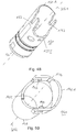
- Figure 3 shows a side view of the two guide sleeves 130 and 140 coupled to one another.
- the two guide sleeves form a two-part, L-shaped guide channel and / or cable duct for the cable of the connector 100.
- the two-part cable duct formed by the two guide sleeves 130, 140 coupled to one another extends from one The mating end 131 of the mating guide sleeve 130 along the mating guide sleeve 130, bends at the angle 103 and runs from there to a cable-side end 141 of the cable-side guide sleeve 140.
- the two-part, L-shaped cable duct has an outer angle side 103A and an inner angle side 103I.
- a cable duct provides and / or forms a free space in the connector in which a cable can be laid along a predetermined path.
- the two-part cable duct is provided by the two guide sleeves 130 and 140, which are each designed as a type of sleeve that resembles a hollow cylinder.
- Figures 4A and 5A show a side view of the plug-side guide sleeve 130 and the cable-side guide sleeve 140.
- the two guide sleeves are shown in a non-assembled, that is, not coupled to one another, namely as individual components.
- the plug-side guide sleeve 130 is designed essentially in the form of a hollow cylinder, the cylinder axis of which extends from the plug-side end 131 of the plug-side guide sleeve 130 to an angled end 132.
- the cable-side guide sleeve 140 is also essentially designed as a hollow cylinder, the cylinder axis of which extends from the cable-side end 141 to the angle-side end 142 of the angle-side guide sleeve 140.
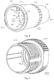
- FIGS 4B and 5B show the two guide sleeves 130 and 140 in a rotated perspective view.
- the essentially hollow cylindrical design of the guide sleeves 130, 140 is shown.
- the cylinder jacket of the two guide sleeves 130, 140 surrounds a likewise essentially cylindrical cavity, namely a cable duct in which the cable of the plug connector 100 is guided.
- a first cable duct KG1 is arranged along this cavity of the plug-side guide sleeve 130, which is shown in FIG Figure 4B is shown by a dashed line and is arranged substantially parallel to the cylinder axis of the plug-side guide sleeve 130.
- a second cable duct KG2 is shown by a dashed line, which essentially coincides with the cylinder axis of the cable-side guide sleeve 140.
- the first cable duct KG1 forms a plug-side cable duct.
- the second cable duct KG2 forms a cable duct on the cable side.
- the two cable ducts KG1 and KG2 do not correspond to the two dashed lines shown in the figures, but are each formed by the entire cavity which is enclosed, formed and / or defined by the respectively assigned guide sleeve 130 or 140.
- the two guide sleeves 130 and 140 are designed in the manner of a miter at their respective angled ends 132 and 142.
- the plug-side guide sleeve 130 has an angled outer edge 132A at the angled end 132, which is elongated with regard to a shortened angled inner edge 132I.
- the plug-side guide sleeve 130 on the angle-side inner edge 132I is not as high and / or long as on the angle-side outer edge 132A.
- the height and / or length refers to the distance from the plug-side end 131 to the angled end 132.
- the plug-in guide sleeve 130 at the angled end 132 is not constant, but rather has a different height and / or length.
- the cylinder jacket of the plug-side guide side 130 is not configured to be constantly high and / or long, but is configured to be approximately and / or essentially “cut off” along an incline S.
- the two angled ends 132 and 142 of the two guide sleeves 130 and 140 are thus bevelled.
- the slope S is inclined essentially by 45 ° and / or inclined by approximately half the angular amount of the angle 103 relative to the direction of the course first cable duct KG1 and / or the first cable routing direction K1 arranged.
- the incline S is also arranged essentially inclined by 45 ° and / or inclined by approximately half the angular amount of the angle 103 relative to the direction of the course of the second cable duct KG2 and / or the second cable routing direction K2.
- the angled inner edge 132I of the plug-in guide sleeve 130 is designed to be shortened by a distance shown in the figures with the reference symbol V 132 compared to the angled outer edge 132A.
- This shortening V 132 of the angled end of the plug-side guide sleeve 130 is approximately as large as the cross section, in particular the inner cross section and / or inner diameter, of the cable-side guide sleeve 140.
- Figure 5A shows that the cable-side guide sleeve 140 is also adapted to the bevel S at its angled end 142.
- the cable-side guide sleeve 140 has an angled outer edge 142A which is made longer by a shortening V 142 than an angled inner edge 142I.
- the shortening V 142 is essentially as large as the cross section, in particular the inner cross section and / or inner diameter, of the plug-side guide sleeve 130.
- Figures 4A and 5A show that the inclined cutting edges of the angled ends 132 and 142 do not exactly adjoin the incline S, but rather the respective guide sleeves can protrude slightly beyond it or are not designed to be completely adjacent to the incline S.
- one of the two guide sleeves here the plug-side guide sleeve 130, for example, can have one or more recesses 133 that are formed in the housing and / or in the cylinder jacket of the guide sleeve 130 and can extend from the angled end 132 in the direction of the plug-in end 131 .
- the plug-side guide sleeve 130 in the exemplary embodiment shown has two recesses 133 opposite one another with respect to the first cable duct KG1.
- the recesses 133 can be parallel to the first Cable duct KG1 and / or the first cable routing direction K1 extend.
- the other guide sleeve here the cable-side guide sleeve 140, has complementary pins 143 which are shown in FIG Figure 5B are shown.
- the pins 143 are arranged in a position that is approximately at right angles to the second cable passage KG2 and / or to the second cable routing direction K2. In the exemplary embodiment shown, the pins 143 point from the inside of the cable-side guide sleeve 140 inward to the second cable duct KG2.
- the pins 143 opposite each other with respect to the second cable duct KG2 are inserted into the two recesses 133 of the other guide sleeve 130 until there is a tight press fit between the two guide sleeves 130 and 140. If the pins 143 are arranged in the desired position in the recesses 133, the two guide sleeves 130 and 140 are in a predetermined, well-defined position relative to one another and are mechanically coupled to one another.
- Figure 4A shows that the recesses 133 are tapered in the direction away from the angled end 132. This taper enables the pins 143 to be firmly clamped in a narrow area of the recesses 133, and also to facilitate the introduction of the pins 143 into an enlarged area of the recesses 133.
- Figures 5A and 5B show that one of the two guide sleeves, here the cable-side guide sleeve 140, has a widening 144 at the angled end 142.
- the inner cavity of the cable-side guide sleeve 140 is thus widened at the angle-side end 142.
- the angle-side end 132 of the plug-side guide sleeve 130 can be inserted into this widening.
- the plug-side guide sleeve 130 does not have to have a special taper, but can be designed with a constant outer diameter at its angled end 132.
- the widening 144 enables a region-wise introduction of the angled, beveled end 132 into the angled, beveled end 142 of the respective guide sleeves 130 and 140. As a result, a clamping connection between the two guide sleeves 130 can be established.
- This also enables the angle-side end of the cable-side guide sleeve 140 to encompass the angle-side end 132 of the plug-side guide sleeve 130.
- This enables the pins 143 protruding perpendicularly to the two directions of the two cable ducts KG1 and KG2 to engage securely and stably in the cutouts 133.
- the guide sleeves 130 and 140 are shown as essentially cylindrical hollow bodies.
- the guide sleeves can also be designed as a differently shaped hollow body, e.g. with a square and / or rectangular cross-section relative to the respective associated cable duct.
- the guide sleeves can thus also be designed as guide housings with an elongated, oval or angular cross-section, e.g. square, hexagonal, octagonal, etc. can be formed.
- the terms “cable-side” and “plug-side” guide sleeve can also be replaced by the more general terms “first” and “second”, especially if the terms are used in relation to guide sleeves, cable ducts, cable routing directions, etc. .
- the specific reference to the specification of the respective guide sleeves or cable ducts as being on the plug-in side or on the cable side only serves to illustrate the exemplary embodiment shown in the figures.
- the cable-side guide sleeve for example, can also have recesses into which pins of the plug-side guide sleeve engage.
- the guide sleeve with the recesses can also have the widening at its angled end.
- the complementary guide sleeve can have their angular end pins which point away from the cylinder axis of the associated cable duct and engage in the complementary recesses of the complementary guide sleeve.
- Figure 6 shows the insulating body 120 of the connector 100 in a perspective view.
- the insulating body 120 has an essentially cylindrical outer surface, the cylinder axis being approximately parallel to the direction of current flow and to the first cable routing direction K1 (cf. Figure 2 ) is arranged.
- the insulating body 120 At its end facing the plug end 101, the insulating body 120 has an opening 123 into which a complementary insulating body with female socket contacts can be inserted.
- the male socket contacts 110 are arranged parallel to the first cable routing direction K1, in the exemplary embodiment shown the five socket contacts 110.
- the insulating body 120 has a rail 126 on one side within the opening 123 for guiding the complementary insulating body of the socket or the complementary plug connector.
- a region of the insulating body 120 which delimits the opening 123 from the outside and defines it in the process is designed as a plug-in region 121 which is essentially designed in the shape of a cylinder jacket.
- the socket contacts 110 protrude from the insulating body.
- a part of the insulating body 110 that is spaced apart from the opening 123 is designed as a connection area 122, in which conductors or wires of the cable can be in contact with the rear sides of the socket contacts 110.
- This connection area 122 is formed adjacent to the angled end 125 of the insulating body 120.
- a grid 124 is formed on its outer surface approximately in the middle of the insulating body 120.
- the grid is arranged along an annular region on the outer surface of the insulating body 120.
- the grid 124 has teeth and beveled indentations arranged in between.
- the grid 124 serves to provide an inhibition of a screwing movement of the screw ring 160, whereby the plug connection is secured.
- Figure 7 shows the screw ring 160 which is rotatably mounted around the insulating body 21.
- the screw ring 160 has a corrugated grip area 161 for easier screwing of the plug connection.
- the screw ring 160 also has a thread 162 which, in the exemplary embodiment, is designed as an external thread.
- the thread 162 is formed in a region of the screw ring 160 that adjoins the plug end 101 (cf. Figure 1 ).
- a guide channel 163 can be formed in the interior of the screw ring 160.
- a locking ring can be arranged, which engages from the outside in the grid 124 of the insulating body 120, for example by means of an engagement nose of the locking ring provided for this purpose.
- both the first cable duct KG1 and the second cable duct KG1 in the two guide sleeves 130 and 140 are essentially straight.
- none of the two cable ducts KG1 and KG2 has a tapering of the cable duct, no bend and / or no kink. This enables a particularly simplified threading of the two guide sleeves onto the cable of the connector.
- the two guide sleeves can only be positioned at an angle to one another after being threaded onto the cable and after the conductors of the cable have been connected to the socket contacts, with the cable also being bent. In this bent state, the two guide sleeves, in which the cable is arranged, are mechanically coupled to one another, e.g.
Claims (13)
- Connecteur enfichable coudé (100) comprenant :- une extrémité enfichable (101) pour l'enfichage du connecteur enfichable (100) et- une extrémité de câble (102) au niveau de laquelle un câble peut être guidé hors du connecteur enfichable (100), dans lequel- le câble peut être guidé de l'extrémité enfichable (101) vers l'extrémité de câble (102) dans des conduits de câble (KG1, KG2) de deux douilles de guidage (130, 140), les deux douilles de guidage (130, 140) étant accouplées de telle façon l'une à l'autre, que les conduits de câble (KG1, KG2) sont disposés de manière à former un angle (103) entre eux, et- les deux conduits de câble (KG1, KG2) des première et deuxième douilles de guidage (130, 140) sont conçus de façon essentiellement rectiligne, les deux douilles de guidage (130, 140) étant accouplées l'une à l'autre au niveau de l'angle (103) au moyen d'un assemblage par serrage ; caractérisé en ce que- chacun des deux conduits de câble (KG1, KG2) est conçu de façon exclusivement rectiligne et sans angle.
- Connecteur enfichable coudé selon la revendication 1, dans lequel les deux douilles de guidage (130, 140) sont conçues respectivement comme des corps creux essentiellement allongés, dans lequel le conduit de câble (KG1 ; KG2) est formé respectivement par l'espace intérieur creux de la douille de guidage (130, 140).
- Connecteur enfichable coudé selon l'une des revendications précédentes, dans lequel les deux douilles de guidage (130, 140) sont conçues comme un onglet à leur extrémité (132, 142) respectivement tournée vers l'angle (103) et accouplées l'une à l'autre.
- Connecteur enfichable coudé selon l'une des revendications précédentes, dans lequel l'une des deux douilles de guidage (130) présente au moins un évidement (133) à son extrémité (132) tournée vers l'angle (103), dans lequel est disposée au moins une tige (143) de l'autre des deux douilles de guidage (140).
- Connecteur enfichable coudé selon la revendication 4, dans lequel l'au moins un évidement (133) se rétrécit dans la direction opposée à l'angle (103).
- Connecteur enfichable coudé selon l'une des revendications précédentes, dans lequel le câble peut être guidé à partir de l'extrémité enfichable (101) vers l'angle (103) du connecteur enfichable (100) dans le conduit de câble (KG1) d'une première des deux douilles de guidage (130), et peut être guidé à partir de l'angle (103) vers l'extrémité de câble (102) dans le conduit de câble (KG2) d'une deuxième des deux douilles de guidage (140).
- Connecteur enfichable coudé selon l'une des revendications précédentes, dans lequel les deux douilles de guidage (130, 140) sont accouplées de telle façon l'une à l'autre par la force et/ou par complémentarité de forme, que le câble peut également être guidé le long de l'angle (103) dans un état non coulé du connecteur enfichable (100).
- Connecteur enfichable coudé selon l'une des revendications précédentes, lequel est conçu comme un connecteur enfichable rond (100) et/ou comme un connecteur enfichable métrique (100).
- Connecteur enfichable coudé selon l'une des revendications précédentes, dans lequel les deux douilles de guidage (130, 140) sont conçues comme des douilles de blindage, lesquelles réduisent le rayonnement électromagnétique.
- Connecteur enfichable coudé selon l'une des revendications précédentes, dans lequel l'une au moins des deux douilles de guidage (130, 140) est conçue comme une pièce en étain coulé sous pression.
- Connecteur enfichable coudé selon l'une des revendications précédentes, dans lequel l'angle (103) mesure entre environ 30° et environ 120°.
- Connecteur enfichable coudé selon l'une des revendications précédentes, dans lequel les deux douilles de guidage (130, 140) sont conçues à partir d'un matériau rigide.
- Procédé d'assemblage d'un connecteur enfichable coudé (100) selon l'une des revendications précédentes, comprenant les étapes suivantes :- insertion d'un câble à travers un conduit de câble (KG1) exclusivement rectiligne et sans angle d'une première douille de guidage (130),- insertion du câble à travers un conduit de câble (KG2) exclusivement rectiligne et sans angle d'une deuxième douille de guidage (140),- raccordement du câble à une extrémité enfichable (101) du connecteur enfichable coudé (100), et- accouplement des première et deuxième douilles de guidage (130, 140) entre elles au moyen d'un assemblage par serrage, de telle façon que les deux conduits de câble (KG1, KG2) forment un angle entre eux.
Applications Claiming Priority (1)
| Application Number | Priority Date | Filing Date | Title |
|---|---|---|---|
| DE102016001466.0A DE102016001466A1 (de) | 2016-02-09 | 2016-02-09 | Gewinkelter Steckverbinder und Verfahren zum Assemblieren |
Publications (2)
| Publication Number | Publication Date |
|---|---|
| EP3206265A1 EP3206265A1 (fr) | 2017-08-16 |
| EP3206265B1 true EP3206265B1 (fr) | 2020-09-16 |
Family
ID=58016509
Family Applications (1)
| Application Number | Title | Priority Date | Filing Date |
|---|---|---|---|
| EP17000200.0A Active EP3206265B1 (fr) | 2016-02-09 | 2017-02-09 | Connecteur enfichable coudé et procédé d'assemblage |
Country Status (2)
| Country | Link |
|---|---|
| EP (1) | EP3206265B1 (fr) |
| DE (1) | DE102016001466A1 (fr) |
Families Citing this family (2)
| Publication number | Priority date | Publication date | Assignee | Title |
|---|---|---|---|---|
| CN108321558A (zh) * | 2018-03-12 | 2018-07-24 | 正泰电气股份有限公司 | 角度转换连接用导体 |
| CN111505356B (zh) * | 2020-04-27 | 2022-09-16 | 贵州电网有限责任公司 | 一种带钝角接头的二次试验线 |
Family Cites Families (7)
| Publication number | Priority date | Publication date | Assignee | Title |
|---|---|---|---|---|
| US4629273A (en) * | 1983-03-28 | 1986-12-16 | Camp James L Van | Electrical cable connector assembly |
| DE9414613U1 (de) * | 1994-09-08 | 1996-01-11 | Interconnectron Ges Fuer Ind S | Elektrischer Stecker |
| DE102006012194A1 (de) * | 2006-03-16 | 2007-09-20 | Escha Bauelemente Gmbh | Geschirmter Steckverbinder und Verfahren zu seiner Herstellung |
| DE202007001523U1 (de) * | 2007-02-02 | 2007-05-31 | Coninvers Elektrotechnische Bauelemente Gmbh | Winkelsteckverbinder mit veränderbarer Abgangsrichtung |
| DE202007005264U1 (de) * | 2007-04-10 | 2008-08-14 | Weidmüller Interface GmbH & Co. KG | Schirmhülse |
| DK2777097T3 (da) * | 2011-11-10 | 2019-11-18 | Hirschmann Automation & Control Gmbh | Skærmet stikforbindelse og fremgangsmåde til fremstilling af en skærmet stikforbindelse |
| DE102013007815B4 (de) * | 2013-05-07 | 2018-01-25 | Yamaichi Electronics Deutschland Gmbh | Schwenkbarer Verbinder und Kontaktierungsverfahren |
-
2016
- 2016-02-09 DE DE102016001466.0A patent/DE102016001466A1/de not_active Withdrawn
-
2017
- 2017-02-09 EP EP17000200.0A patent/EP3206265B1/fr active Active
Non-Patent Citations (1)
| Title |
|---|
| None * |
Also Published As
| Publication number | Publication date |
|---|---|
| EP3206265A1 (fr) | 2017-08-16 |
| DE102016001466A1 (de) | 2017-08-10 |
Similar Documents
| Publication | Publication Date | Title |
|---|---|---|
| EP2417673B1 (fr) | Connecteur électrique à fiches | |
| EP2076943B1 (fr) | Connecteur xlr | |
| EP1355386B1 (fr) | Connecteur à fiche rond pour des câbles électriques blindés | |
| DE2212560C2 (de) | Elektrische Steckverbindung mit zwei Steckverbindern | |
| DE10146329A1 (de) | Elektrischer Kabelstecker | |
| EP3338326B1 (fr) | Connecteur | |
| EP2797175B1 (fr) | Fiche pour un câble de données et/ou de télécommunications multi-brins | |
| EP3735722B1 (fr) | Support de contact et connecteur pour un agencement de contacts hybride blindé | |
| EP1158610B1 (fr) | Connecteur de câble enfichable | |
| EP3206265B1 (fr) | Connecteur enfichable coudé et procédé d'assemblage | |
| WO2014067595A1 (fr) | Connecteur à fiche à partie isolante | |
| EP3627636A1 (fr) | Connecteur enfichable électrique, raccord de modules et ensemble de carte de circuits imprimés | |
| EP1981132A2 (fr) | Douille d'ecran | |
| DE102015114040B3 (de) | Kabelsteckverbinder mit einer Schirmhülse und Verfahren zu seiner Herstellung | |
| DE3137262C2 (de) | Elektrischer Steckverbinder für ein Zugentlastungsseil enthaltende Kabel | |
| DE102013113878B4 (de) | Steckverbinder mit Einzeladerabdichtung | |
| EP1632009B1 (fr) | Element de contact et chambre de conduction complementaire pour un connecteur male ou femelle utilise en technique de raccordement autodenudant | |
| DE19627971C2 (de) | BNC-Stecker | |
| DE102022203226B3 (de) | Rundsteckverbinder und Verfahren zum Herstellen eines Rundsteckverbinders | |
| DE4307728A1 (de) | Steckverbinder | |
| AT410614B (de) | Kabelstecker mit einem steckergehäuse und elektrischen kontaktelementen | |
| DE102022203174B3 (de) | Rundsteckverbinder und Verfahren zum Herstellen eines Rundsteckverbinders | |
| DE2728025C2 (fr) | ||
| DE3941398A1 (de) | Adapter fuer fernmeldetechnische geraete | |
| DE102020108287A1 (de) | Steckverbinder für eine Steckverbindung |
Legal Events
| Date | Code | Title | Description |
|---|---|---|---|
| PUAI | Public reference made under article 153(3) epc to a published international application that has entered the european phase |
Free format text: ORIGINAL CODE: 0009012 |
|
| STAA | Information on the status of an ep patent application or granted ep patent |
Free format text: STATUS: THE APPLICATION HAS BEEN PUBLISHED |
|
| AK | Designated contracting states |
Kind code of ref document: A1 Designated state(s): AL AT BE BG CH CY CZ DE DK EE ES FI FR GB GR HR HU IE IS IT LI LT LU LV MC MK MT NL NO PL PT RO RS SE SI SK SM TR |
|
| AX | Request for extension of the european patent |
Extension state: BA ME |
|
| STAA | Information on the status of an ep patent application or granted ep patent |
Free format text: STATUS: REQUEST FOR EXAMINATION WAS MADE |
|
| 17P | Request for examination filed |
Effective date: 20180215 |
|
| RBV | Designated contracting states (corrected) |
Designated state(s): AL AT BE BG CH CY CZ DE DK EE ES FI FR GB GR HR HU IE IS IT LI LT LU LV MC MK MT NL NO PL PT RO RS SE SI SK SM TR |
|
| STAA | Information on the status of an ep patent application or granted ep patent |
Free format text: STATUS: EXAMINATION IS IN PROGRESS |
|
| 17Q | First examination report despatched |
Effective date: 20181210 |
|
| RIC1 | Information provided on ipc code assigned before grant |
Ipc: H01R 24/40 20110101AFI20200219BHEP Ipc: H01R 43/16 20060101ALI20200219BHEP Ipc: H01R 24/54 20110101ALN20200219BHEP |
|
| GRAP | Despatch of communication of intention to grant a patent |
Free format text: ORIGINAL CODE: EPIDOSNIGR1 |
|
| STAA | Information on the status of an ep patent application or granted ep patent |
Free format text: STATUS: GRANT OF PATENT IS INTENDED |
|
| INTG | Intention to grant announced |
Effective date: 20200401 |
|
| GRAS | Grant fee paid |
Free format text: ORIGINAL CODE: EPIDOSNIGR3 |
|
| GRAA | (expected) grant |
Free format text: ORIGINAL CODE: 0009210 |
|
| STAA | Information on the status of an ep patent application or granted ep patent |
Free format text: STATUS: THE PATENT HAS BEEN GRANTED |
|
| AK | Designated contracting states |
Kind code of ref document: B1 Designated state(s): AL AT BE BG CH CY CZ DE DK EE ES FI FR GB GR HR HU IE IS IT LI LT LU LV MC MK MT NL NO PL PT RO RS SE SI SK SM TR |
|
| REG | Reference to a national code |
Ref country code: GB Ref legal event code: FG4D Free format text: NOT ENGLISH |
|
| REG | Reference to a national code |
Ref country code: CH Ref legal event code: EP |
|
| REG | Reference to a national code |
Ref country code: DE Ref legal event code: R096 Ref document number: 502017007248 Country of ref document: DE |
|
| REG | Reference to a national code |
Ref country code: IE Ref legal event code: FG4D Free format text: LANGUAGE OF EP DOCUMENT: GERMAN |
|
| REG | Reference to a national code |
Ref country code: AT Ref legal event code: REF Ref document number: 1314996 Country of ref document: AT Kind code of ref document: T Effective date: 20201015 |
|
| PG25 | Lapsed in a contracting state [announced via postgrant information from national office to epo] |
Ref country code: GR Free format text: LAPSE BECAUSE OF FAILURE TO SUBMIT A TRANSLATION OF THE DESCRIPTION OR TO PAY THE FEE WITHIN THE PRESCRIBED TIME-LIMIT Effective date: 20201217 Ref country code: NO Free format text: LAPSE BECAUSE OF FAILURE TO SUBMIT A TRANSLATION OF THE DESCRIPTION OR TO PAY THE FEE WITHIN THE PRESCRIBED TIME-LIMIT Effective date: 20201216 Ref country code: SE Free format text: LAPSE BECAUSE OF FAILURE TO SUBMIT A TRANSLATION OF THE DESCRIPTION OR TO PAY THE FEE WITHIN THE PRESCRIBED TIME-LIMIT Effective date: 20200916 Ref country code: BG Free format text: LAPSE BECAUSE OF FAILURE TO SUBMIT A TRANSLATION OF THE DESCRIPTION OR TO PAY THE FEE WITHIN THE PRESCRIBED TIME-LIMIT Effective date: 20201216 Ref country code: HR Free format text: LAPSE BECAUSE OF FAILURE TO SUBMIT A TRANSLATION OF THE DESCRIPTION OR TO PAY THE FEE WITHIN THE PRESCRIBED TIME-LIMIT Effective date: 20200916 Ref country code: FI Free format text: LAPSE BECAUSE OF FAILURE TO SUBMIT A TRANSLATION OF THE DESCRIPTION OR TO PAY THE FEE WITHIN THE PRESCRIBED TIME-LIMIT Effective date: 20200916 |
|
| REG | Reference to a national code |
Ref country code: NL Ref legal event code: MP Effective date: 20200916 |
|
| PG25 | Lapsed in a contracting state [announced via postgrant information from national office to epo] |
Ref country code: LV Free format text: LAPSE BECAUSE OF FAILURE TO SUBMIT A TRANSLATION OF THE DESCRIPTION OR TO PAY THE FEE WITHIN THE PRESCRIBED TIME-LIMIT Effective date: 20200916 Ref country code: RS Free format text: LAPSE BECAUSE OF FAILURE TO SUBMIT A TRANSLATION OF THE DESCRIPTION OR TO PAY THE FEE WITHIN THE PRESCRIBED TIME-LIMIT Effective date: 20200916 |
|
| REG | Reference to a national code |
Ref country code: LT Ref legal event code: MG4D |
|
| PG25 | Lapsed in a contracting state [announced via postgrant information from national office to epo] |
Ref country code: RO Free format text: LAPSE BECAUSE OF FAILURE TO SUBMIT A TRANSLATION OF THE DESCRIPTION OR TO PAY THE FEE WITHIN THE PRESCRIBED TIME-LIMIT Effective date: 20200916 Ref country code: PT Free format text: LAPSE BECAUSE OF FAILURE TO SUBMIT A TRANSLATION OF THE DESCRIPTION OR TO PAY THE FEE WITHIN THE PRESCRIBED TIME-LIMIT Effective date: 20210118 Ref country code: CZ Free format text: LAPSE BECAUSE OF FAILURE TO SUBMIT A TRANSLATION OF THE DESCRIPTION OR TO PAY THE FEE WITHIN THE PRESCRIBED TIME-LIMIT Effective date: 20200916 Ref country code: LT Free format text: LAPSE BECAUSE OF FAILURE TO SUBMIT A TRANSLATION OF THE DESCRIPTION OR TO PAY THE FEE WITHIN THE PRESCRIBED TIME-LIMIT Effective date: 20200916 Ref country code: SM Free format text: LAPSE BECAUSE OF FAILURE TO SUBMIT A TRANSLATION OF THE DESCRIPTION OR TO PAY THE FEE WITHIN THE PRESCRIBED TIME-LIMIT Effective date: 20200916 Ref country code: EE Free format text: LAPSE BECAUSE OF FAILURE TO SUBMIT A TRANSLATION OF THE DESCRIPTION OR TO PAY THE FEE WITHIN THE PRESCRIBED TIME-LIMIT Effective date: 20200916 |
|
| PG25 | Lapsed in a contracting state [announced via postgrant information from national office to epo] |
Ref country code: ES Free format text: LAPSE BECAUSE OF FAILURE TO SUBMIT A TRANSLATION OF THE DESCRIPTION OR TO PAY THE FEE WITHIN THE PRESCRIBED TIME-LIMIT Effective date: 20200916 Ref country code: AL Free format text: LAPSE BECAUSE OF FAILURE TO SUBMIT A TRANSLATION OF THE DESCRIPTION OR TO PAY THE FEE WITHIN THE PRESCRIBED TIME-LIMIT Effective date: 20200916 Ref country code: PL Free format text: LAPSE BECAUSE OF FAILURE TO SUBMIT A TRANSLATION OF THE DESCRIPTION OR TO PAY THE FEE WITHIN THE PRESCRIBED TIME-LIMIT Effective date: 20200916 Ref country code: IS Free format text: LAPSE BECAUSE OF FAILURE TO SUBMIT A TRANSLATION OF THE DESCRIPTION OR TO PAY THE FEE WITHIN THE PRESCRIBED TIME-LIMIT Effective date: 20210116 |
|
| REG | Reference to a national code |
Ref country code: DE Ref legal event code: R097 Ref document number: 502017007248 Country of ref document: DE |
|
| PG25 | Lapsed in a contracting state [announced via postgrant information from national office to epo] |
Ref country code: SK Free format text: LAPSE BECAUSE OF FAILURE TO SUBMIT A TRANSLATION OF THE DESCRIPTION OR TO PAY THE FEE WITHIN THE PRESCRIBED TIME-LIMIT Effective date: 20200916 |
|
| PLBE | No opposition filed within time limit |
Free format text: ORIGINAL CODE: 0009261 |
|
| STAA | Information on the status of an ep patent application or granted ep patent |
Free format text: STATUS: NO OPPOSITION FILED WITHIN TIME LIMIT |
|
| 26N | No opposition filed |
Effective date: 20210617 |
|
| PG25 | Lapsed in a contracting state [announced via postgrant information from national office to epo] |
Ref country code: DK Free format text: LAPSE BECAUSE OF FAILURE TO SUBMIT A TRANSLATION OF THE DESCRIPTION OR TO PAY THE FEE WITHIN THE PRESCRIBED TIME-LIMIT Effective date: 20200916 Ref country code: SI Free format text: LAPSE BECAUSE OF FAILURE TO SUBMIT A TRANSLATION OF THE DESCRIPTION OR TO PAY THE FEE WITHIN THE PRESCRIBED TIME-LIMIT Effective date: 20200916 |
|
| PG25 | Lapsed in a contracting state [announced via postgrant information from national office to epo] |
Ref country code: MC Free format text: LAPSE BECAUSE OF FAILURE TO SUBMIT A TRANSLATION OF THE DESCRIPTION OR TO PAY THE FEE WITHIN THE PRESCRIBED TIME-LIMIT Effective date: 20200916 |
|
| REG | Reference to a national code |
Ref country code: BE Ref legal event code: MM Effective date: 20210228 |
|
| PG25 | Lapsed in a contracting state [announced via postgrant information from national office to epo] |
Ref country code: CH Free format text: LAPSE BECAUSE OF NON-PAYMENT OF DUE FEES Effective date: 20210228 Ref country code: LU Free format text: LAPSE BECAUSE OF NON-PAYMENT OF DUE FEES Effective date: 20210209 Ref country code: LI Free format text: LAPSE BECAUSE OF NON-PAYMENT OF DUE FEES Effective date: 20210228 Ref country code: IT Free format text: LAPSE BECAUSE OF FAILURE TO SUBMIT A TRANSLATION OF THE DESCRIPTION OR TO PAY THE FEE WITHIN THE PRESCRIBED TIME-LIMIT Effective date: 20200916 |
|
| PG25 | Lapsed in a contracting state [announced via postgrant information from national office to epo] |
Ref country code: IE Free format text: LAPSE BECAUSE OF NON-PAYMENT OF DUE FEES Effective date: 20210209 |
|
| PG25 | Lapsed in a contracting state [announced via postgrant information from national office to epo] |
Ref country code: BE Free format text: LAPSE BECAUSE OF NON-PAYMENT OF DUE FEES Effective date: 20210228 |
|
| REG | Reference to a national code |
Ref country code: AT Ref legal event code: MM01 Ref document number: 1314996 Country of ref document: AT Kind code of ref document: T Effective date: 20220209 |
|
| PG25 | Lapsed in a contracting state [announced via postgrant information from national office to epo] |
Ref country code: AT Free format text: LAPSE BECAUSE OF NON-PAYMENT OF DUE FEES Effective date: 20220209 |
|
| PGFP | Annual fee paid to national office [announced via postgrant information from national office to epo] |
Ref country code: FR Payment date: 20230215 Year of fee payment: 7 |
|
| PG25 | Lapsed in a contracting state [announced via postgrant information from national office to epo] |
Ref country code: HU Free format text: LAPSE BECAUSE OF FAILURE TO SUBMIT A TRANSLATION OF THE DESCRIPTION OR TO PAY THE FEE WITHIN THE PRESCRIBED TIME-LIMIT; INVALID AB INITIO Effective date: 20170209 |
|
| PGFP | Annual fee paid to national office [announced via postgrant information from national office to epo] |
Ref country code: GB Payment date: 20230215 Year of fee payment: 7 Ref country code: DE Payment date: 20220622 Year of fee payment: 7 |
|
| PG25 | Lapsed in a contracting state [announced via postgrant information from national office to epo] |
Ref country code: NL Free format text: LAPSE BECAUSE OF NON-PAYMENT OF DUE FEES Effective date: 20200923 Ref country code: CY Free format text: LAPSE BECAUSE OF FAILURE TO SUBMIT A TRANSLATION OF THE DESCRIPTION OR TO PAY THE FEE WITHIN THE PRESCRIBED TIME-LIMIT Effective date: 20200916 |