EP3206012B1 - Verfahren und systeme zur bewertung der wirksamkeit eines asphalten-inhibitors - Google Patents
Verfahren und systeme zur bewertung der wirksamkeit eines asphalten-inhibitors Download PDFInfo
- Publication number
- EP3206012B1 EP3206012B1 EP17155890.1A EP17155890A EP3206012B1 EP 3206012 B1 EP3206012 B1 EP 3206012B1 EP 17155890 A EP17155890 A EP 17155890A EP 3206012 B1 EP3206012 B1 EP 3206012B1
- Authority
- EP
- European Patent Office
- Prior art keywords
- reservoir
- precipitant
- inhibitor
- oil sample
- microfluidic device
- Prior art date
- Legal status (The legal status is an assumption and is not a legal conclusion. Google has not performed a legal analysis and makes no representation as to the accuracy of the status listed.)
- Active
Links
Images



Classifications
-
- B—PERFORMING OPERATIONS; TRANSPORTING
- B01—PHYSICAL OR CHEMICAL PROCESSES OR APPARATUS IN GENERAL
- B01L—CHEMICAL OR PHYSICAL LABORATORY APPARATUS FOR GENERAL USE
- B01L3/00—Containers or dishes for laboratory use, e.g. laboratory glassware; Droppers
- B01L3/50—Containers for the purpose of retaining a material to be analysed, e.g. test tubes
- B01L3/502—Containers for the purpose of retaining a material to be analysed, e.g. test tubes with fluid transport, e.g. in multi-compartment structures
- B01L3/5027—Containers for the purpose of retaining a material to be analysed, e.g. test tubes with fluid transport, e.g. in multi-compartment structures by integrated microfluidic structures, i.e. dimensions of channels and chambers are such that surface tension forces are important, e.g. lab-on-a-chip
- B01L3/50273—Containers for the purpose of retaining a material to be analysed, e.g. test tubes with fluid transport, e.g. in multi-compartment structures by integrated microfluidic structures, i.e. dimensions of channels and chambers are such that surface tension forces are important, e.g. lab-on-a-chip characterised by the means or forces applied to move the fluids
-
- B—PERFORMING OPERATIONS; TRANSPORTING
- B01—PHYSICAL OR CHEMICAL PROCESSES OR APPARATUS IN GENERAL
- B01F—MIXING, e.g. DISSOLVING, EMULSIFYING OR DISPERSING
- B01F33/00—Other mixers; Mixing plants; Combinations of mixers
- B01F33/30—Micromixers
-
- B—PERFORMING OPERATIONS; TRANSPORTING
- B01—PHYSICAL OR CHEMICAL PROCESSES OR APPARATUS IN GENERAL
- B01F—MIXING, e.g. DISSOLVING, EMULSIFYING OR DISPERSING
- B01F35/00—Accessories for mixers; Auxiliary operations or auxiliary devices; Parts or details of general application
- B01F35/71—Feed mechanisms
- B01F35/717—Feed mechanisms characterised by the means for feeding the components to the mixer
- B01F35/71725—Feed mechanisms characterised by the means for feeding the components to the mixer using centrifugal forces
-
- B—PERFORMING OPERATIONS; TRANSPORTING
- B01—PHYSICAL OR CHEMICAL PROCESSES OR APPARATUS IN GENERAL
- B01L—CHEMICAL OR PHYSICAL LABORATORY APPARATUS FOR GENERAL USE
- B01L3/00—Containers or dishes for laboratory use, e.g. laboratory glassware; Droppers
- B01L3/50—Containers for the purpose of retaining a material to be analysed, e.g. test tubes
- B01L3/502—Containers for the purpose of retaining a material to be analysed, e.g. test tubes with fluid transport, e.g. in multi-compartment structures
- B01L3/5027—Containers for the purpose of retaining a material to be analysed, e.g. test tubes with fluid transport, e.g. in multi-compartment structures by integrated microfluidic structures, i.e. dimensions of channels and chambers are such that surface tension forces are important, e.g. lab-on-a-chip
-
- C—CHEMISTRY; METALLURGY
- C09—DYES; PAINTS; POLISHES; NATURAL RESINS; ADHESIVES; COMPOSITIONS NOT OTHERWISE PROVIDED FOR; APPLICATIONS OF MATERIALS NOT OTHERWISE PROVIDED FOR
- C09K—MATERIALS FOR MISCELLANEOUS APPLICATIONS, NOT PROVIDED FOR ELSEWHERE
- C09K8/00—Compositions for drilling of boreholes or wells; Compositions for treating boreholes or wells, e.g. for completion or for remedial operations
- C09K8/52—Compositions for preventing, limiting or eliminating depositions, e.g. for cleaning
- C09K8/524—Compositions for preventing, limiting or eliminating depositions, e.g. for cleaning organic depositions, e.g. paraffins or asphaltenes
-
- C—CHEMISTRY; METALLURGY
- C10—PETROLEUM, GAS OR COKE INDUSTRIES; TECHNICAL GASES CONTAINING CARBON MONOXIDE; FUELS; LUBRICANTS; PEAT
- C10G—CRACKING HYDROCARBON OILS; PRODUCTION OF LIQUID HYDROCARBON MIXTURES, e.g. BY DESTRUCTIVE HYDROGENATION, OLIGOMERISATION, POLYMERISATION; RECOVERY OF HYDROCARBON OILS FROM OIL-SHALE, OIL-SAND, OR GASES; REFINING MIXTURES MAINLY CONSISTING OF HYDROCARBONS; REFORMING OF NAPHTHA; MINERAL WAXES
- C10G75/00—Inhibiting corrosion or fouling in apparatus for treatment or conversion of hydrocarbon oils, in general
- C10G75/04—Inhibiting corrosion or fouling in apparatus for treatment or conversion of hydrocarbon oils, in general by addition of antifouling agents
-
- G—PHYSICS
- G01—MEASURING; TESTING
- G01N—INVESTIGATING OR ANALYSING MATERIALS BY DETERMINING THEIR CHEMICAL OR PHYSICAL PROPERTIES
- G01N21/00—Investigating or analysing materials by the use of optical means, i.e. using sub-millimetre waves, infrared, visible or ultraviolet light
- G01N21/01—Arrangements or apparatus for facilitating the optical investigation
- G01N21/03—Cuvette constructions
- G01N21/07—Centrifugal type cuvettes
-
- G—PHYSICS
- G01—MEASURING; TESTING
- G01N—INVESTIGATING OR ANALYSING MATERIALS BY DETERMINING THEIR CHEMICAL OR PHYSICAL PROPERTIES
- G01N21/00—Investigating or analysing materials by the use of optical means, i.e. using sub-millimetre waves, infrared, visible or ultraviolet light
- G01N21/17—Systems in which incident light is modified in accordance with the properties of the material investigated
- G01N21/25—Colour; Spectral properties, i.e. comparison of effect of material on the light at two or more different wavelengths or wavelength bands
- G01N21/251—Colorimeters; Construction thereof
- G01N21/253—Colorimeters; Construction thereof for batch operation, i.e. multisample apparatus
-
- G—PHYSICS
- G01—MEASURING; TESTING
- G01N—INVESTIGATING OR ANALYSING MATERIALS BY DETERMINING THEIR CHEMICAL OR PHYSICAL PROPERTIES
- G01N21/00—Investigating or analysing materials by the use of optical means, i.e. using sub-millimetre waves, infrared, visible or ultraviolet light
- G01N21/75—Systems in which material is subjected to a chemical reaction, the progress or the result of the reaction being investigated
- G01N21/77—Systems in which material is subjected to a chemical reaction, the progress or the result of the reaction being investigated by observing the effect on a chemical indicator
- G01N21/82—Systems in which material is subjected to a chemical reaction, the progress or the result of the reaction being investigated by observing the effect on a chemical indicator producing a precipitate or turbidity
-
- G—PHYSICS
- G01—MEASURING; TESTING
- G01N—INVESTIGATING OR ANALYSING MATERIALS BY DETERMINING THEIR CHEMICAL OR PHYSICAL PROPERTIES
- G01N33/00—Investigating or analysing materials by specific methods not covered by groups G01N1/00 - G01N31/00
- G01N33/22—Fuels; Explosives
-
- G—PHYSICS
- G01—MEASURING; TESTING
- G01N—INVESTIGATING OR ANALYSING MATERIALS BY DETERMINING THEIR CHEMICAL OR PHYSICAL PROPERTIES
- G01N33/00—Investigating or analysing materials by specific methods not covered by groups G01N1/00 - G01N31/00
- G01N33/26—Oils; Viscous liquids; Paints; Inks
- G01N33/28—Oils, i.e. hydrocarbon liquids
- G01N33/2823—Raw oil, drilling fluid or polyphasic mixtures
-
- G—PHYSICS
- G01—MEASURING; TESTING
- G01N—INVESTIGATING OR ANALYSING MATERIALS BY DETERMINING THEIR CHEMICAL OR PHYSICAL PROPERTIES
- G01N33/00—Investigating or analysing materials by specific methods not covered by groups G01N1/00 - G01N31/00
- G01N33/26—Oils; Viscous liquids; Paints; Inks
- G01N33/28—Oils, i.e. hydrocarbon liquids
- G01N33/2835—Specific substances contained in the oils or fuels
-
- G—PHYSICS
- G01—MEASURING; TESTING
- G01N—INVESTIGATING OR ANALYSING MATERIALS BY DETERMINING THEIR CHEMICAL OR PHYSICAL PROPERTIES
- G01N35/00—Automatic analysis not limited to methods or materials provided for in any single one of groups G01N1/00 - G01N33/00; Handling materials therefor
- G01N35/00029—Automatic analysis not limited to methods or materials provided for in any single one of groups G01N1/00 - G01N33/00; Handling materials therefor provided with flat sample substrates, e.g. slides
- G01N35/00069—Automatic analysis not limited to methods or materials provided for in any single one of groups G01N1/00 - G01N33/00; Handling materials therefor provided with flat sample substrates, e.g. slides whereby the sample substrate is of the bio-disk type, i.e. having the format of an optical disk
-
- G—PHYSICS
- G01—MEASURING; TESTING
- G01N—INVESTIGATING OR ANALYSING MATERIALS BY DETERMINING THEIR CHEMICAL OR PHYSICAL PROPERTIES
- G01N35/00—Automatic analysis not limited to methods or materials provided for in any single one of groups G01N1/00 - G01N33/00; Handling materials therefor
- G01N35/02—Automatic analysis not limited to methods or materials provided for in any single one of groups G01N1/00 - G01N33/00; Handling materials therefor using a plurality of sample containers moved by a conveyor system past one or more treatment or analysis stations
- G01N35/025—Automatic analysis not limited to methods or materials provided for in any single one of groups G01N1/00 - G01N33/00; Handling materials therefor using a plurality of sample containers moved by a conveyor system past one or more treatment or analysis stations having a carousel or turntable for reaction cells or cuvettes
-
- B—PERFORMING OPERATIONS; TRANSPORTING
- B01—PHYSICAL OR CHEMICAL PROCESSES OR APPARATUS IN GENERAL
- B01L—CHEMICAL OR PHYSICAL LABORATORY APPARATUS FOR GENERAL USE
- B01L2200/00—Solutions for specific problems relating to chemical or physical laboratory apparatus
- B01L2200/10—Integrating sample preparation and analysis in single entity, e.g. lab-on-a-chip concept
-
- B—PERFORMING OPERATIONS; TRANSPORTING
- B01—PHYSICAL OR CHEMICAL PROCESSES OR APPARATUS IN GENERAL
- B01L—CHEMICAL OR PHYSICAL LABORATORY APPARATUS FOR GENERAL USE
- B01L2300/00—Additional constructional details
- B01L2300/06—Auxiliary integrated devices, integrated components
- B01L2300/0627—Sensor or part of a sensor is integrated
-
- B—PERFORMING OPERATIONS; TRANSPORTING
- B01—PHYSICAL OR CHEMICAL PROCESSES OR APPARATUS IN GENERAL
- B01L—CHEMICAL OR PHYSICAL LABORATORY APPARATUS FOR GENERAL USE
- B01L2300/00—Additional constructional details
- B01L2300/08—Geometry, shape and general structure
- B01L2300/0803—Disc shape
-
- B—PERFORMING OPERATIONS; TRANSPORTING
- B01—PHYSICAL OR CHEMICAL PROCESSES OR APPARATUS IN GENERAL
- B01L—CHEMICAL OR PHYSICAL LABORATORY APPARATUS FOR GENERAL USE
- B01L2300/00—Additional constructional details
- B01L2300/08—Geometry, shape and general structure
- B01L2300/0861—Configuration of multiple channels and/or chambers in a single devices
- B01L2300/0867—Multiple inlets and one sample wells, e.g. mixing, dilution
-
- B—PERFORMING OPERATIONS; TRANSPORTING
- B01—PHYSICAL OR CHEMICAL PROCESSES OR APPARATUS IN GENERAL
- B01L—CHEMICAL OR PHYSICAL LABORATORY APPARATUS FOR GENERAL USE
- B01L2300/00—Additional constructional details
- B01L2300/08—Geometry, shape and general structure
- B01L2300/0861—Configuration of multiple channels and/or chambers in a single devices
- B01L2300/087—Multiple sequential chambers
-
- B—PERFORMING OPERATIONS; TRANSPORTING
- B01—PHYSICAL OR CHEMICAL PROCESSES OR APPARATUS IN GENERAL
- B01L—CHEMICAL OR PHYSICAL LABORATORY APPARATUS FOR GENERAL USE
- B01L2400/00—Moving or stopping fluids
- B01L2400/04—Moving fluids with specific forces or mechanical means
- B01L2400/0403—Moving fluids with specific forces or mechanical means specific forces
- B01L2400/0409—Moving fluids with specific forces or mechanical means specific forces centrifugal forces
-
- C—CHEMISTRY; METALLURGY
- C09—DYES; PAINTS; POLISHES; NATURAL RESINS; ADHESIVES; COMPOSITIONS NOT OTHERWISE PROVIDED FOR; APPLICATIONS OF MATERIALS NOT OTHERWISE PROVIDED FOR
- C09K—MATERIALS FOR MISCELLANEOUS APPLICATIONS, NOT PROVIDED FOR ELSEWHERE
- C09K2208/00—Aspects relating to compositions of drilling or well treatment fluids
- C09K2208/20—Hydrogen sulfide elimination
-
- C—CHEMISTRY; METALLURGY
- C10—PETROLEUM, GAS OR COKE INDUSTRIES; TECHNICAL GASES CONTAINING CARBON MONOXIDE; FUELS; LUBRICANTS; PEAT
- C10G—CRACKING HYDROCARBON OILS; PRODUCTION OF LIQUID HYDROCARBON MIXTURES, e.g. BY DESTRUCTIVE HYDROGENATION, OLIGOMERISATION, POLYMERISATION; RECOVERY OF HYDROCARBON OILS FROM OIL-SHALE, OIL-SAND, OR GASES; REFINING MIXTURES MAINLY CONSISTING OF HYDROCARBONS; REFORMING OF NAPHTHA; MINERAL WAXES
- C10G2300/00—Aspects relating to hydrocarbon processing covered by groups C10G1/00 - C10G99/00
- C10G2300/10—Feedstock materials
- C10G2300/1033—Oil well production fluids
-
- G—PHYSICS
- G01—MEASURING; TESTING
- G01N—INVESTIGATING OR ANALYSING MATERIALS BY DETERMINING THEIR CHEMICAL OR PHYSICAL PROPERTIES
- G01N21/00—Investigating or analysing materials by the use of optical means, i.e. using sub-millimetre waves, infrared, visible or ultraviolet light
- G01N21/01—Arrangements or apparatus for facilitating the optical investigation
- G01N21/03—Cuvette constructions
- G01N2021/0325—Cells for testing reactions, e.g. containing reagents
- G01N2021/0328—Arrangement of two or more cells having different functions for the measurement of reactions
-
- G—PHYSICS
- G01—MEASURING; TESTING
- G01N—INVESTIGATING OR ANALYSING MATERIALS BY DETERMINING THEIR CHEMICAL OR PHYSICAL PROPERTIES
- G01N21/00—Investigating or analysing materials by the use of optical means, i.e. using sub-millimetre waves, infrared, visible or ultraviolet light
- G01N21/01—Arrangements or apparatus for facilitating the optical investigation
- G01N21/03—Cuvette constructions
- G01N2021/0346—Capillary cells; Microcells
-
- G—PHYSICS
- G01—MEASURING; TESTING
- G01N—INVESTIGATING OR ANALYSING MATERIALS BY DETERMINING THEIR CHEMICAL OR PHYSICAL PROPERTIES
- G01N21/00—Investigating or analysing materials by the use of optical means, i.e. using sub-millimetre waves, infrared, visible or ultraviolet light
- G01N21/75—Systems in which material is subjected to a chemical reaction, the progress or the result of the reaction being investigated
- G01N21/77—Systems in which material is subjected to a chemical reaction, the progress or the result of the reaction being investigated by observing the effect on a chemical indicator
- G01N2021/7769—Measurement method of reaction-produced change in sensor
- G01N2021/7783—Transmission, loss
-
- G—PHYSICS
- G01—MEASURING; TESTING
- G01N—INVESTIGATING OR ANALYSING MATERIALS BY DETERMINING THEIR CHEMICAL OR PHYSICAL PROPERTIES
- G01N21/00—Investigating or analysing materials by the use of optical means, i.e. using sub-millimetre waves, infrared, visible or ultraviolet light
- G01N21/75—Systems in which material is subjected to a chemical reaction, the progress or the result of the reaction being investigated
- G01N21/77—Systems in which material is subjected to a chemical reaction, the progress or the result of the reaction being investigated by observing the effect on a chemical indicator
- G01N2021/7769—Measurement method of reaction-produced change in sensor
- G01N2021/7786—Fluorescence
-
- G—PHYSICS
- G01—MEASURING; TESTING
- G01N—INVESTIGATING OR ANALYSING MATERIALS BY DETERMINING THEIR CHEMICAL OR PHYSICAL PROPERTIES
- G01N35/00—Automatic analysis not limited to methods or materials provided for in any single one of groups G01N1/00 - G01N33/00; Handling materials therefor
- G01N35/02—Automatic analysis not limited to methods or materials provided for in any single one of groups G01N1/00 - G01N33/00; Handling materials therefor using a plurality of sample containers moved by a conveyor system past one or more treatment or analysis stations
- G01N35/04—Details of the conveyor system
- G01N2035/0439—Rotary sample carriers, i.e. carousels
- G01N2035/0446—Combinations of the above
- G01N2035/0449—Combinations of the above using centrifugal transport of liquid
-
- G—PHYSICS
- G01—MEASURING; TESTING
- G01N—INVESTIGATING OR ANALYSING MATERIALS BY DETERMINING THEIR CHEMICAL OR PHYSICAL PROPERTIES
- G01N21/00—Investigating or analysing materials by the use of optical means, i.e. using sub-millimetre waves, infrared, visible or ultraviolet light
- G01N21/01—Arrangements or apparatus for facilitating the optical investigation
- G01N21/03—Cuvette constructions
- G01N21/0332—Cuvette constructions with temperature control
-
- G—PHYSICS
- G01—MEASURING; TESTING
- G01N—INVESTIGATING OR ANALYSING MATERIALS BY DETERMINING THEIR CHEMICAL OR PHYSICAL PROPERTIES
- G01N21/00—Investigating or analysing materials by the use of optical means, i.e. using sub-millimetre waves, infrared, visible or ultraviolet light
- G01N21/62—Systems in which the material investigated is excited whereby it emits light or causes a change in wavelength of the incident light
- G01N21/63—Systems in which the material investigated is excited whereby it emits light or causes a change in wavelength of the incident light optically excited
- G01N21/64—Fluorescence; Phosphorescence
- G01N21/645—Specially adapted constructive features of fluorimeters
-
- G—PHYSICS
- G01—MEASURING; TESTING
- G01N—INVESTIGATING OR ANALYSING MATERIALS BY DETERMINING THEIR CHEMICAL OR PHYSICAL PROPERTIES
- G01N21/00—Investigating or analysing materials by the use of optical means, i.e. using sub-millimetre waves, infrared, visible or ultraviolet light
- G01N21/62—Systems in which the material investigated is excited whereby it emits light or causes a change in wavelength of the incident light
- G01N21/63—Systems in which the material investigated is excited whereby it emits light or causes a change in wavelength of the incident light optically excited
- G01N21/65—Raman scattering
Definitions
- the present application relates to test methods, and systems for evaluating the effectiveness of organic and inorganic scale inhibitors.
- Inorganic and organic scale inhibitors can be used for flow assurance during the production, transportation, and processing of petroleum reservoir fluids.
- asphaltene deposition a type of organic scaling
- Unexpected precipitation and the subsequent potential for deposition of asphaltene aggregates can cause reservoir impairment, plugging of wells and flowlines, equipment fouling issues, and processing challenges for facilities.
- the costs associated with the precipitation and deposition of asphaltenes from reservoir fluids during production, transportation, sample handling, and processing of reservoir fluids have been estimated to be on the order of billions of dollars worldwide as described in Rogel, E., Ovalles, C. and Moir, M., "Asphaltene Stability in Crude Oils and Petroleum Materials by Solubility Profile Analysis," Energy & Fuels, Vol. 24(8), 2010, pp. 4369-4374 .
- Asphaltene deposition Since mechanisms of aggregation and deposition are not completely understood, prediction, prevention, and remediation techniques may be difficult to implement.
- One approach to minimize the possibility for asphaltene deposition is to add one or more asphaltene inhibitors to the reservoir fluid.
- the asphaltene inhibitor(s) act to slow the formation of asphaltene aggregates; thereby keeping asphaltenes suspended in solution. Since the aggregation behavior of asphaltenes is challenging to predict, the selection of a suitable asphaltene inhibitor that is effective for a particular reservoir fluid is often achieved through an empirical screening process, where a pre-defined library of dispersants are applied to the crude oil sample and evaluated for effectiveness by the addition of a precipitant that induces flocculation.
- a "good” asphaltene inhibitor will keep asphaltenes suspended and a “poor” asphaltene inhibitor will show precipitation and sedimentation. This process is commonly known as the Asphaltene Dispersion Test (ADT).
- ADT Asphaltene Dispersion Test
- the optimal solution may be a combination of several asphaltene inhibitors, which are typically in the 50-1000 ppm range. Determining a good combination is often a time consuming process that must be completed for individual oil samples because the asphaltenes vary from one oilfield to another.
- a precipitant like n-heptane is added to a sample of crude oil plus dispersant and an optical detection system measures the transmitted and back-scattered light. Vertical scans are performed, in which a motorized stage moves the optical system along the length of the vial in 40 micrometer increments.
- NACE TM 0374-2001 and NACE TM 0197-97 or their latest iteration are also tested. These protocols require that the fluid to be tested (e.g. seawater) is mixed with a scale inhibitor in a glass jar, which is then placed into a temperature-controlled chamber/bath. Then, after waiting for an amount of time which is representative or the inhibitor exposure time, the results of the reaction are checked either visually (by absorption, scattering, cloudiness, precipitation) or quantitatively (by subsampling from the test jar and using the appropriate tool for the scale of interest).
- Jennings et al, 2014, p. 1-14 discloses a dead-oil asphaltene stability analysis method for comparing asphaltene inhibitor performance.
- the publication " Decanting and mixing of supernatant human blood plasma on centrifugal microfluidic platform” discloses a compact disk (CD) microfluidic platform for separating human blood plasma from a whole blood sample.
- US 2011/0269151 A1 discloses a centrifugal microfluidic device and an immunoassay method using such a device.
- US 2015/0238955 A1 discloses a microfluidic device for reducing inspection time and errors.
- US 2011/0203353 A1 furthermore discloses a method for determining the effectiveness of an asphaltene deposition inhibitor in oilfield applications.
- a method according to independent claim 1 preferably a parallel asphaltene dispersion test (ADT) method, is provided in which centrifugal separation is used (as a substitute for conventional gravimetric sedimentation in the traditional ASTM D7061 method).
- a centrifugal microfluidic system according to independent claim 5 is provided, which can include a light source and a charge-coupled device (CCD) camera that are configured to scan one or more chambers of a rotatable disc corresponding to areas in which asphaltenes can precipitate.
- CCD charge-coupled device
- the method can include introducing an oil sample to a sample reservoir in the microfluidic device, which can be mounted on a disc, introducing a precipitant to a precipitant reservoir in the microfluidic device, which can be mounted on the disc, introducing an asphaltene inhibitor to an inhibitor reservoir in the microfluidic device, which can be mounted on the disc and/or a solvent to a solvent reservoir in the microfluidic device, which can be mounted on the disc, and rotating the disc and the microfluidic device mounted thereon to generate centrifugal force to cause the sample, precipitant, solvent, and inhibitor to travel radially outward toward an analysis chamber where the asphaltenes in the oil sample may precipitate out of the oil sample and settle radially outwardly under the influence of the centrifugal force.
- the flow of fluids on the disc is controllable based at least in part on the rotational speed of the disc. As a result, it is possible to meter out various ratios of solvent, inhibitor, oil, and precipitant for testing by altering the speed of the disc.
- microfluidics refers to a device, apparatus, or system that deals with the behavior, precise control, and manipulation of fluids that are geometrically constrained to a small, typically sub-millimeter, scale.
- the device, apparatus, or system can employ small, typically sub-millimeter, scale channels that are etched into planar substrates, such as glass, where networks of these embedded channels transport the sample from one operation to the next.
- the manipulation of small volumes of fluid enables precise control of reagents and seamless automation of several consecutive steps.
- the subject matter of the disclosure relates to the evaluation of the effectiveness of asphaltene inhibitors using a centrifugal microfluidic testing apparatus and system. Specifically, this disclosure presents a rapid and automated method for screening asphaltene inhibitors using microfluidic technology.
- Fig. 1 depicts an illustrative embodiment of a system 101 for automated fluid analysis of an oil sample.
- the system 101 includes a disc 102 with multiple microfluidic devices 103 arranged circumferentially about the disc 102. The details of the construction of each micro fluidic device 103 will be described in greater detail below with reference to Fig. 2 .
- the microfluidic devices 103 may be integral with the disc 102 or may be separate pieces that are fixed to the disc 102.
- the disc 102 is constructed to spin as a platter in a clockwise and/or counter-clockwise direction about an axis labeled A-A.
- the system 101 also includes a motor 105 coupled to the disc 102.
- the motor 105 is constructed to regulate the speed, acceleration, and direction of the rotation of the disc 102 about the axis A-A.
- the motor 105 may be an electric motor operating on DC or AC power.
- the system 101 also includes an optical detection system 104 for measuring the optical absorbance of fluid at an analysis chamber 120 that is part of the micro fluidic device 103 as the analysis chamber 120 rotates passed the optical detection system 104.
- the optical detection system 104 can include a light source 104a located on one side of the disc 102 and a CCD detector (or camera) 104b on the other side of the disc 102 so that the CCD captures an image of the light transmitted through the analysis chamber 120 along the lengthwise dimension of the analysis chamber 120 of the micro fluidic device 103. Note that the optical detection system 104 is fixed in position and does not rotate with the disc 102.
- the disc 102 is rotated so that the analysis chamber 120 of the microfluidic device 103 is passed over the fixed imaging area of the optical detection system 104.
- the optical detection system 104 may include a spectrophotometer to measure the absorbance or fluorescence over the lengthwise dimension of the analysis chamber 120 of the rotating microfluidic device 103.
- the optical detection system 104 may include a light scattering optical system for measuring asphaltene precipitation onsets and also the degree of precipitation.
- the system 101 can also include a computer processing system 107 that can be programmed with suitable control logic that interfaces to the motor 105 and the optical detection system 104 via wired or wireless signal paths therebetween.
- the computer processing system 107 may be embodied as at least one controller (e.g., microcontrollers) and/or at least one general purpose computer configured (i.e., programmed) to execute specific control logic, as described in greater detail hereinbelow.
- the control logic of the computer processing system 107 (which can be embodied in software that is loaded from persistent memory and executed in the computing platform of the computer processing system 107) is configured to control the different parts of the system 101 to carry out an automated sequence of operations (workflow) that characterizes the dispersion of an oil sample mixed with an asphaltene inhibitor.
- the control logic can be configured by a testing script, which is input into and executed by the computer processing system 107 to perform automatic control operations as specified by the testing script.
- the control logic may set rotational speed and direction of the disc 102 according to a rotational test protocol so that fluids in the microfluidic device 103 can be mixed in a predefined manner.
- the computer processing system 107 can include a graphical user interface that allows a user to specify the sequence of automatic control operations and/or the parameters (such as flow rates, temperatures, etc.) for such automatic control operations.
- the micro fluidic device 103 may be formed from a substrate 106, which may be made of glass.
- the substrate 106 may be mountable to the disc 102 as a separate piece or may be integrally formed with the disc 102.
- the micro fluidic device 103 defines various micro fluidic chambers and passageways interconnecting the chambers, as will be described below.
- the substrate 106 may be a temperature-controlled region (e.g., resistive heaters, oven, cooling bath, etc.) that may be used to control the temperature at various locations on the microfluidic device 103, including the various micro fluidic chambers and passageways.
- the temperature control may be used to test for the presence of fines and waxes in an oil sample, as will be described in greater detail below.
- Such microfluidic chambers and passageways may be machined, etched, or otherwise formed in the microfluidic device 103 as will be appreciated by those of ordinary skill in the art. Fluids move radially outward between the chambers and through the passageways of the micro fluidic device 103 as facilitated by the centrifugal and/or capillary forces resulting from rotation of the micro fluidic device 103 on the disc 102 driven by the motor 105 about the axis A-A.
- the micro fluidic device 103 has an oil sample reservoir 110 located near the center (axis A-A) of the disc 102.
- the oil sample reservoir 110 holds an oil sample.
- the oil sample can include lighter (more volatile) molecular weight components as well as heavy (less volatile) molecular weight components such as heavy oil and bitumen.
- the oil sample may be manually introduced into the oil sample reservoir 110, such as with a pipette or syringe.
- the oil sample may be automatically introduced into the oil sample reservoir 110, such as with a syringe pump, which may be electrically operated.
- the computer processing system 107 may be programmed with suitable control logic that interfaces to such an electrically operated syringe pump via wired or wireless signal paths therebetween to control operation of the syringe pump.
- the system 101 also has a solvent reservoir 112 located near the center (axis A-A) of disc 102.
- the solvent reservoir 112 holds a solvent, which can dissolve asphaltene solids when the solvent is present in the oil sample.
- the solvent can be toluene, dichloromethane (DCM), xylenes, benzene, methyl naphthalene, cyclohexane, tetrahydrofuran (THF), chloroform, trichloroethylene, tetrachloroethylene, carbon tetrachloride, carbon disulfide, and other suitable solvents.
- the solvent may be manually introduced into the solvent reservoir 112, such as with a pipette or syringe.
- the solvent may be automatically introduced into the solvent reservoir 112, such as with a syringe pump, which may be electrically operated.
- the computer processing system 107 may be programmed with suitable control logic that interfaces to such an electrically operated syringe pump via wired or wireless signal paths therebetween to control operation of the syringe pump.
- the micro fluidic device 103 also has an inhibitor reservoir 113 located near the center (axis A-A) of disc 102.
- the inhibitor reservoir 113 is configured to hold one or more asphaltene inhibitor(s).
- the asphaltene inhibitor(s) is an additive that can be blended with the oil sample to identify an appropriate additive and additive concentration that retards or prevents the undesirable reaction that forms asphaltene aggregates when the oil sample is mixed with a precipitant at concentrations that result in the formation of asphaltene aggregates. Such analysis may be useful to mitigate problems that can arise from asphaltene precipitation of the particular oil during its production and/or transport.
- the asphaltene inhibitor(s) may be manually introduced into the inhibitor reservoir 113, such as with a pipette or syringe.
- the asphaltene inhibitor(s) may be automatically introduced into the inhibitor reservoir 113, such as with a syringe pump, which may be electrically operated.
- the computer processing system 107 may be programmed with suitable control logic that interfaces to such an electrically operated syringe pump via wired or wireless signal paths therebetween to control operation of the syringe pump.
- the micro fluidic device 103 also has a precipitant reservoir 114 located near the center (axis A-A) of disc 102.
- the precipitant reservoir 114 is configured to hold a precipitant that can cause asphaltenes to precipitate from the oil sample when the precipitant is mixed with the oil at sufficient concentrations.
- the precipitant can be an n-alkane (such as n-heptane (C 7 H 16 ), n-hexane (C 6 H 14 ), or n-pentane (C 5 H 12 )) or other solvents, such as petroleum ether, ethyl acetate, alcohols or any other solvent, which can cause asphaltene precipitation due to a limited solubility.
- the precipitant may be manually introduced into the precipitant reservoir 114, such as with a pipette or syringe.
- the precipitant may be automatically introduced into the precipitant reservoir 114, such as with a syringe pump, which may be electrically operated.
- the computer processing system 107 may be programmed with suitable control logic that interfaces to such an electrically operated syringe pump via wired or wireless signal paths therebetween to control operation of the syringe pump.
- the solvent reservoir 112 and the inhibitor reservoir 113 are both fluidly coupled to a dilution chamber 115 that is located radially outward with respect to the reservoirs 112, 113.
- a solvent channel 112a fluidly couples the solvent reservoir 112 to the dilution chamber 115.
- An inhibitor channel 113a fluidly couples the inhibitor reservoir 113 to the dilution chamber 115.
- the dimensions of the solvent channel 112a and the inhibitor channel 113a are configured so that when the microfluidic device 103 is rotated at a predetermined speed, metered amounts of solvent and/or inhibitor will be displaced from the respective reservoirs 112, 113 and into the dilution chamber 115 under the influence of centrifugal force caused by the rotation of the micro fluidic device 103 with the disc 102.
- the movement of the solvent and the inhibitor will be a function at least of the viscosity of the fluid, the geometry and dimensions of the channels 112a, 113a, and the rotational speed of the micro fluidic device 103.
- the dilution chamber 115 can provide a space for the solvent and inhibitor to be metered out and/or mixed.
- the dilution chamber 115 can be configured such that the inhibitor is diluted with the solvent in an automated way using only the micro fluidic device (i.e., "on-chip”), which avoids manually diluting the inhibitor off of the micro fluidic device 103 (i.e., "off-chip”) and loading the diluted inhibitor onto the micro fluidic device 103 in a separate operation.
- the solvent/inhibitor/oil ratio may be predetermined based on the standard or test protocol employed.
- the inhibitor is mixed with the solvent and the oil so that the desired amount of inhibitor is in a range from about 50 ppm to 1000 ppm. It may be desirable to minimize the dosages of solvent and inhibitor to keep cost low during implementation in the field, while ensuring stabilization of asphaltenes. Therefore, when the dosages of solvent and inhibitor are minimized, the crude oil comprises the majority of the mixture that is mixed with the precipitant.
- the oil sample reservoir 110 and the dilution chamber 115 are both fluidly coupled to a first mixing chamber 116 that is located radially outward with respect to the oil sample reservoir 110 and dilution chamber 115.
- Channel 110a fluidly couples the oil sample reservoir 110 to the first mixing chamber 116.
- Channel 115a fluidly couples the dilution chamber 115 to the first mixing chamber 116.
- the first mixing chamber 116 provides microfluidic mixing of the fluids from the dilution chamber 115 and oil displaced from the oil sample reservoir 110.
- metered amounts of the fluid in the dilution chamber 115 and oil will be displaced from their respective dilution chamber 115 and oil sample reservoir 110 and into the first mixing chamber 116 under the influence of centrifugal force caused by the rotation of the microfluidic device 103 with the disc 102.
- the precipitant reservoir 114 is fluidly coupled by channel 114a to a first volumetric gate 117 that is located radially outward with respect to the precipitant reservoir 114.
- Precipitant can be displaced from the precipitant reservoir 114 to the first volumetric gate 117 under the influence of centrifugal force when the micro fluidic device 103 rotates with the disc 102.
- the outlet of the first volumetric gate 117 can optionally be selectively opened or closed, such as by means of a flapper valve, to permit fluid therein to move radially outwardly from the first volumetric gate 117.
- the opening of the outlet of the first volumetric gate 117 can be controlled so that the fluids displaced from the first volumetric gate 117 can be accurately metered out from the first volumetric gate 117.
- the first mixing chamber 116 is fluidly coupled to a second volumetric gate 118 that is located radially outward with respect to the first mixing chamber 116.
- Channel 116a fluidly couples the first mixing chamber 116 to the second volumetric gate 118.
- Fluid can be displaced from the first mixing chamber 116 to the second volumetric gate 118 under the influence of centrifugal force when the micro fluidic device 103 rotates with the disc 102.
- the outlet of the second volumetric gate 118 can optionally be selectively opened or closed, such as by means of a flapper valve, to permit fluid therein to move radially outwardly from the second volumetric gate 118.
- the opening of the outlet of the second volumetric gate 118 can be controlled so that the fluids displaced from the second volumetric gate 118 can be accurately metered out from the second volumetric gate 118 through channel 118a.
- the outlets of the first and second volumetric gates 117, 118 are both fluidly coupled to a second mixing chamber 119 that is located radially outward with respect to the volumetric gates 117, 118.
- Channel 117a fluidly couples the outlet of the first volumetric gate 117 to the second mixing chamber 119.
- Channel 118a fluidly couples the outlet of the second volumetric gate 118 to the second mixing chamber 119.
- the second mixing chamber 119 provides micro fluidic mixing of the fluids from the volumetric gates 117, 118.
- metered amounts of the precipitant can be dispensed into the second mixing chamber 119 by operation of the first volumetric gate 117 and metered amounts of the fluid from the first mixing chamber 116 can be displaced into the second mixing chamber 119 by operation of the second volumetric gate 118 so that microfluidic mixing of the precipitant and the oil and solvent/inhibitor can take place in the second mixing chamber 119 under the influence of centrifugal force caused by the rotation of the micro fluidic device 103 with the disc 102.
- the first and second volumetric gates 117, 118 are chambers with accurately known volumes that may have built-in valving mechanisms.
- the first and second volumetric gates 117, 118 may accurately dispense fluid from their respective chambers using such valving mechanisms so that a desired dilution/mixing ratio of fluids issuing from the first and second volumetric gates is achieved in the second mixing chamber 119.
- the first and second volumetric gates 117, 118 can be activated by different means.
- one or both of the volumetric gates 117, 118 can be configured with valves at an exit port on a radially outward end of the respective gates 117, 118.
- Such valves can be configured to open above a predetermined rotational speed of the device 103 and to remain closed when the rotational speed of the micro fluidic device 103 is below the predetermined rotational speed.
- An example of a speed responsive valve of a volumetric gate may be a spring-loaded valve that is constructed so that at a rotational speed below a predetermined threshold, the valve will be subject to a centrifugal force below the spring load of the valve which does not open the valve so that that fluid entering the volumetric gate from an inlet port will tend to fill the chamber of the volumetric gate.
- the spring-loaded valve may be subject to a centrifugal force above the spring load of the valve, which causes the valve to open at the exit port so that fluid in the volumetric gate will tend to drain from the volumetric gate radially outwardly.
- the volumetric gates 117, 118 may not include any valve mechanism. Instead, all of the fluids to be mixed may be accurately dosed (e.g., using an accurate pipette) and dispensed into the reservoirs 110, 112, 113, 114 before the microfluidic device 103 is rotated. Then, the micro fluidic device 103 is rotated until all of the closed fluids are mixed so that the mixture includes all of the dosed amounts so that the fluid concentrations are known.
- all of the fluids to be mixed may be accurately dosed (e.g., using an accurate pipette) and dispensed into the reservoirs 110, 112, 113, 114 before the microfluidic device 103 is rotated. Then, the micro fluidic device 103 is rotated until all of the closed fluids are mixed so that the mixture includes all of the dosed amounts so that the fluid concentrations are known.
- the outlet of the second mixing chamber 119 is fluidly coupled to an analysis chamber 120 that is located radially outward with respect to the second mixing chamber 119.
- Channel 119a fluidly couples the outlet of the second mixing chamber 119 to the analysis chamber 120.
- Mixed fluids in the second mixing chamber 119 may be displaced radially outwardly from the second mixing chamber 119 into the analysis chamber 120 under the influence of centrifugal force caused by the rotation of the microfluidic device 103 with the disc 102.
- the direction and speed of rotation of the microfluidic device 103 can be controlled to control the radial flow of fluid between chambers on the device 103.
- the rotation speed and direction can be controlled according to a protocol based on the configuration of the microfluidic device 103 (e.g., chamber geometry, channel sizes, etc.).
- the analysis chamber 120 can be constructed as an integrated microfluidic optical absorbance flow cell. Examples of such a flow cell are described in Sieben, V. J., et al., "Microfluidic colourimetric chemical analysis system: Application to nitrite detection, " Analytical Methods 2(5), 2010, pp. 484-491 ; and Hwang, H. et al., "Lab-on-a-Disc for Simultaneous Determination of Nutrients in Water," Analytical Chemistry 85, 2013, pp. 2954-2960 .
- the mixing of the precipitant and the oil sample in the second mixing chamber 119 can cause asphaltenes to precipitate from the mixture.
- Such precipitated asphaltenes are typically referred to as asphaltene floccules or asphaltene flocks.
- the asphaltene flocks are carried as a suspension in the liquid phase of the mixture into the analysis chamber 120.
- the liquid phase of the mixture includes the maltenes of the oil sample, which are the lower molecular weight components of the oil sample that remain after removing the precipitated asphaltenes.
- the maltenes are also soluble in the precipitant.
- the centrifugal force caused by the rotation of the microfluidic device 103 with the disc 102 causes the precipitated asphaltene flock, if present, to settle rapidly near the distal end of the analysis chamber 120.
- the rotational speed of the microfluidic device 103 may be set by a user to test for sedimentation, i.e., of asphaltene flocculates.
- the rotational speed for sedimentation may be set by a user as a function of desired centrifugal force, i.e., for a desired equivalent of "g".
- Centrifugal force can range from 1g to 20,000 g, but will typically range from 1 g to 10 g for the separation of flocculates having a size on an order of a micrometer. More centrifugal force will cause sedimentation/collection of smaller asphaltene particles, permitting more stringent control over the screening for effective inhibitors.
- the analysis chamber 120 may be constructed as an optical flow cell, which can be scanned by the optical detection system 104, which, as noted above, may include a spectrophotometer in communication with the computer processing system 107.
- the spectrophotometer can be operated to measure optical absorbance over the lengthwise dimension R of the analysis chamber 120 of the rotating microfluidic device 103. Such measurements can be used to generate a graph of optical transmission through the analysis chamber 120 as a function of radial distance R of the analysis chamber 120. An example of such graph is shown in Fig. 3 .
- the transmittance of light through crude oil is dependent on the concentration of asphaltenes, since asphaltenes strongly absorb light.
- the change in transmittance over time along the length R of the analysis chamber 120 can be used to monitor asphaltene stability by determining changes over time in asphaltene content in the different regions or entire length R of the analysis chamber 120.
- optical properties such as light transmission
- liquid phase maltenes
- solid phase asphaltenes
- optical properties can be evaluated to detect changes in the mixture's solids concentration (asphaltenes concentration) at various radial positions in the chamber 120. More specifically, as the dispersed asphaltene flock particles scatter light, light transmission will increase in areas that are losing solids (asphaltenes) and decrease (if not already opaque) in areas that are gaining solids (asphaltenes).
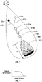
- Fig. 4A shows that upon initial introduction of the oil/inhibitor/solvent mixture into the analysis chamber 120, a relatively evenly dispersed mixture of solids exists along substantially the entire length R of the analysis chamber 120.
- Fig. 4B shows an initial trace after the oil/inhibitor/precipitant mixture is introduced into the analysis chamber 120. In this case, the light transmission through the analysis chamber 120 is relatively uniform along the entire length R of the analysis chamber 120.
- the dispersion breaks down and asphaltene solids start separating from the oil/solvent/inhibitor mixture and move towards the radially outer portion of the analysis chamber 120. See, e.g., Fig. 4C .
- the transmission of light through the analysis chamber 120 increases at the radially inner portions of the analysis chamber. See, e.g., Fig. 4D , traces 2 to 4 showing plots of transmittance through the analysis chamber 120 at different times.
- Fig. 4D illustrates that over a certain period of time after initial introduction of the oil/inhibitor/precipitant mixture, light transmission through the analysis chamber 120 at radially inner positions of the analysis chamber 120 increases as asphaltene solids settle radially outwardly over time, i.e., from traces 2 to 4.
- the transmission of light decreases when there is an increase of asphaltene solids settling there. See, e.g., Fig. 4E.
- Fig. 4F shows additional traces 5 to 12 over the analysis chamber 120 that illustrate that the light transmittance has increased almost the entire length R of the analysis chamber 120 with the exception of the radially outer end where the asphaltene solids have collected.
- the transmittance data that represents light transmission through the analysis chamber 120 at varying radial positions of the analysis chamber 120 can be used to calculate an instability index, which is a measure of normalized potential for solids flocculation and settling from the oil sample.
- the instability index is a calculation of the change in integral transmission between time 0 and a time t, normalized by the maximum theoretical transmission, resulting in a calculated value from 0 to 1.0.
- An instability index value of 0 indicates a completely stable sample with no change in the transmittance trace, whereas an instability value of 1 indicates a completely unstable sample with a full change in the transmittance trace occurring.
- the transmittance trace will behave similar to that illustrated in Figs. 4B, 4D, and 4F and the destabilized asphaltenes will, over the period of time the microfluidic device 103 is spun, largely settle to the radially outer end of the analysis chamber 120.
- the greater the amount of asphaltenes destabilized the larger the magnitude of the transmittance increase.
- the inhibitor that can reduce the asphaltene destabilization as evidenced by the lowest instability index (least transmittance change) provides the best inhibition.
- tests on different inhibitors or different inhibitor ratios can be performed to evaluate and select inhibitors that are most effective for a specific crude oil sample.
- Fig. 5 illustrates a workflow for evaluating an asphaltene inhibitor using the system 101 described above.
- one or more of the oil sample reservoir 110, the solvent reservoir 112, the inhibitor reservoir 113, and the precipitant reservoir 114 are filled or dosed, respectively, with sample, solvent, inhibitor, and precipitant.
- the filled or dosed microfluidic device 103 is rotated at a first rotational speed with the disc 102 so that the solvent and the inhibitor flows radially outward into the dilution chamber 115 and into the first mixing chamber 116, while the oil sample flows radially outward into the first mixing chamber 116 to mix with the solvent and the inhibitor.
- the mixture formed in the first mixing chamber 116 flows radially outward to the second volumetric gate 118.
- the precipitant flows radially outward into the first volumetric gate 117.
- the first rotational speed can be set so that the first and second volumetric gates 117, 118 remain closed in the case that valves actuated at predefined rotational speeds are used.
- the dimensions of the channels 112a, 113a, and 110a are configured so that the ratio of solvent to inhibitor to oil can be controlled and the oil sample can be diluted with a predetermined concentration of the solvent.
- the dimensions of the channels 112a and 110a may be configured so that 1000 ppm inhibitor is diluted down to 50 ppm with toluene and then mixed with the oil sample. The diluted inhibitor can then be mixed with precipitant at a desired precipitant-to-oil ratio, such as 40:1, or even 1:1.
- microfluidic mixing that occurs in the first mixing chamber 116 allows the solvent of the sample/solvent mixture to dissolve most if not all of the asphaltene content of the sample/solvent mixture (if any asphaltene content is present from the oil sample). At least a portion of the fluid in the first mixing chamber 116 flows into the second volumetric gate 118.
- the disc 102 is rotated at a second speed, different from the first speed, to open the first and second volumetric gates 117, 118.
- the first and second volumetric gates 117, 118 are opened, the mixture of the solvent, inhibitor, and oil as well as the precipitant flow radially outward to the second mixing chamber 119 for mixing, whereupon the resultant mixture flows radially outward into the analysis chamber 120.
- the oil/precipitant/inhibitor mixture After the oil/precipitant/inhibitor mixture enters the analysis chamber 120, there may be a "waiting time" during which the disc 102 and microfluidic device 103 are not rotated in order to allow for the onset of precipitation of asphaltenes.
- Such waiting time may be dependent on the sample, the inhibitor, and/or the precipitant, as well as the respective concentrations. Also, the waiting time may be dependent on a predefined test protocol.
- the disc 102 At the end of any such "waiting time”, at block 503, the disc 102 is rotated at or above the second speed so that the analysis chamber 120 passes the detection point of the optical detection system 104, which is located at a fixed position.
- the optical detection system 104 may measure the optical absorbance of the fluid mixture in the analysis chamber 120 as a function of radial distance in the analysis chamber 120.
- the computer processing system 107 may output or store one or more graphs, like that shown in Fig. 3 of the optical transmission as a function of radius.
- the optical absorbance may be measured periodically, such as once per revolution of the disc 102, to determine the effectiveness of the mixed inhibitor, as discussed above.
- a comparison of graphs like that in Fig. 3 , taken over a period of time, can indicate trends in the asphaltene sedimentation. For example, a good inhibitor will slow down asphaltene sedimentation, whereas a poor inhibitor will not slow down asphaltene sedimentation.
- batches of asphaltene inhibitors can be screened and appropriate concentrations selected.
- the microfluidic devices 103 can be used to conduct various experiments.
- the micro fluidic devices 103 can be used to conduct parallel ADT experiments in which the same inhibitor (i.e., the same chemical) is evaluated at different ratios with the oil/solvent/precipitant mixture.
- the same inhibitor i.e., the same chemical
- a plurality of the micro fluidic devices 103 are loaded onto the disc 102 and the amount of the inhibitor filled into the respective inhibitor reservoirs 113 is varied across multiple micro fluidic devices 103, while the volumes of precipitant, solvent, and oil in their respective reservoirs is fixed so that the effect of different concentrations on asphaltene dispersion for a specific inhibitor can be evaluated.
- the micro fluidic devices 103 can be used to conduct parallel ADT experiments in which different inhibitors (i.e., different chemicals) are evaluated at the same ratio with the oil/solvent/precipitant mixture.
- a plurality of micro fluidic devices 103 is loaded onto a disc 102 and equal amounts (by volume) of different inhibitors are loaded into each inhibitor reservoir 113 while the volumes of precipitant, solvent, and oil in their respective reservoirs is fixed so that the effect of different inhibitors on asphaltene dispersion can be evaluated.
- the relative concentrations between oil, inhibitor, and precipitant are determined by a standard protocol or method employed. For instance ASTM D7601-04 requires at least 97% precipitant (destabilizing solvent) and no more than 2.67% oil.
- the concentration of various inhibitors are kept constant to evaluate the relative ability of the inhibitors in keeping asphaltenes suspended. Then, once a select group of inhibitors are determined as being relatively better at keeping asphaltenes suspended at the tested concentration, the concentrations of those inhibitors may be varied to determine respective optimum concentrations for the selected group of inhibitors. In one example, the inhibitor that provides the best results at the lowest inhibitor concentration is identified as the preferred inhibitor.
- the substrate 106 of the microfluidic device 103 may be temperature-controlled to regulate the temperature along the fluid pathways of the microfluidic device 103.
- the temperature may be regulated to test for the presence of fines and waxes in a crude oil sample in accordance with the disclosure of International Patent Application PCT/US2015/037896 entitled "Microfluidic Method for Detection of Fines, Waxes, and Asphaltenes in Oil". It will be appreciated that for such testing for the presence of fines and waxes, the microfluidic device 103 may be modified to be the same as that of the microfluidic chip 111 of International Patent Application PCT/US2015/037896 with the exception of the pumps described therein.
- microfluidic device 103 may be made to adapt the microfluidic device 103 for use in detecting the presence of fines and waxes in accordance with International Patent Application PCT/US2015/037896 , which will be appreciated by those of ordinary skill in the art.
- centrifugal force caused by rotation of the disc 102 and the microfluidic device 103 can be used to adjust the pressure of the oil sample through the microfluidic device 103.
- the microfluidic device 603 may be formed from a substrate 606, which may be made of glass.
- the substrate 606 may be mountable to the disc 102 as a separate piece or may be integrally formed with the disc 102.
- the microfluidic device 603 defines various microfluidic chambers and passageways interconnecting the chambers, as will be described below.
- the substrate 606 may include a temperature-controlled region (e.g., resistive heaters, oven, cooling bath, etc.) that may be used to control the temperature at various locations on the microfluidic device 603, including the various microfluidic chambers and passageways.
- the microfluidic chambers and passageways may be machined, etched, or otherwise formed in the microfluidic device 603 as will be appreciated by those of ordinary skill in the art. Fluids move radially outward between the chambers and through the passageways of the microfluidic device 603 as facilitated by the centrifugal and/or capillary forces resulting from rotation of the microfluidic device 603 on the disc 102 driven by the motor 105 about the axis A-A.
- the microfluidic device 603 has an oil sample reservoir 610 located near the center (axis A-A) of the disc 102.
- the oil sample reservoir 610 holds an oil sample that has been premixed with an inhibitor.
- the oil sample can include lighter (more volatile) molecular weight components as well as heavy (less volatile) molecular weight components such as heavy oil and bitumen.
- the oil and inhibitor may be manually premixed and introduced into the oil sample reservoir 610, such as with a pipette or syringe.
- the microfluidic device 603 also has a precipitant reservoir 614 located near the center (axis A-A) of disc 102.
- the precipitant reservoir 614 is configured to hold a precipitant that can cause asphaltene to precipitate from the oil sample when the precipitant is mixed with the oil at sufficient concentrations.
- the precipitant can be an n-alkane (such as n-heptane (C 7 H 16 ), n-hexane (C 6 H 14 ), or n-pentane (C 5 H 12 )) or other solvents, such as petroleum ether, ethyl acetate, alcohols or any other solvent, which can cause asphaltene precipitation due to a limited solubility.
- the precipitant may be manually introduced into the precipitant reservoir 614, such as with a pipette or syringe.
- the oil sample reservoir 610 and the precipitant reservoir 614 are both fluidly coupled to a first mixing chamber 619a that is located radially outward with respect to the oil sample reservoir 610 and the precipitant reservoir 614.
- Channel 610a fluidly couples the oil sample reservoir 610 to the first mixing chamber 619a.
- Channel 614a fluidly couples the precipitant reservoir 614 to the first mixing chamber 619a.
- the first mixing chamber 619a provides a first micro-mixing stage for micro fluidic mixing of the oil, inhibitor, and the precipitant.
- metered amounts of the oil/inhibitor and precipitant will be displaced from their respective reservoirs 610 and 614 into the first mixing chamber 619a under the influence of centrifugal force caused by the rotation of the microfluidic device 603 with the disc 102.
- the first mixing chamber 619a is fluidly coupled to a second mixing chamber 619b located radially outward from the first mixing chamber 619a.
- the second mixing chamber 619b acts as a second microfluidic mixing stage for the oil/inhibitor/precipitant mixture.
- the second mixing chamber 619b is fluidly coupled to a third mixing chamber 619c that is located radially outward from the second mixing chamber 619b.
- the third mixing chamber 619b acts as a third micro fluidic mixing stage for the oil/inhibitor/precipitant mixture.
- the third mixing chamber 619c is fluidly coupled to an analysis chamber 620 that is located radially outward with respect to the third mixing chamber 619c.
- the mixed fluids in the third mixing chamber 619c may be displaced radially outwardly into the analysis chamber 620 under the influence of centrifugal force caused by the rotation of the microfluidic device 603 with the disc 102. Thereafter, the scanning and analysis of the mixture in the analysis chamber 620 progresses in the same manner described above with reference to Figs. 4A to 4F .
- Fig. 8 illustrates a workflow for evaluating an asphaltene inhibitor using the system 101 described above, but modified to incorporate the microfluidic device 603 instead of microfluidic device 103.
- the oil sample reservoir 610 and the precipitant reservoir 614 are filled or dosed, respectively, with crude oil/inhibitor and precipitant.
- the filled or dosed microfluidic device 603 is rotated at a first rotational speed with the disc 102 so that the crude oil/inhibitor and the precipitant flow radially outward successively into the first mixing chamber 619a, the second mixing chamber 619b, and the third mixing chamber 619c.
- the dimensions of the channels 610a and 614a are configured so that the ratio of oil/inhibitor to precipitant can be controlled.
- the inhibitor/oil is then mixed with precipitant at a desired precipitant-to-oil ratio, such as 40:1, or even 1:1.
- microfluidic mixing that occurs in the mixing chambers 619a, 619b, and 619c allows the oil/inhibitor to mix fully with the precipitant before moving radially outward from the third mixing chamber 619c. Also, in block 801, eventually all of the fluid loaded onto the microfluidic device 603 will move from the third mixing chamber 619c into the analysis chamber 620.
- the oil/precipitant/inhibitor mixture After the oil/precipitant/inhibitor mixture enters the analysis chamber 620, there may be a "waiting time" during which the disc 102 is not rotated to allow for the onset of precipitation, which may be dependent on the sample, inhibitor, and/or precipitant, as well as the respective concentrations. Also, the waiting time may be dependent on a predefined test protocol. At the end of any such waiting time, at block 802, the disc 102 and microfluidic device 603 are rotated together at a second, solids-separation speed to promote and speed up the separation of asphaltene solids from the crude oil.
- the analysis chamber 620 passes the detection point of the optical detection system 104, which is located at a fixed position.
- the optical detection system 104 may measure the optical absorbance (or light transmission) of the fluid mixture in the analysis chamber 620 as a function of radial distance R in the analysis chamber 620.
- the computer processing system 107 may output or store one or more graphs or traces, like that shown in Fig. 7 of the optical transmission as a function of radial distance R ( Fig. 6 ).
- the optical absorbance may be measured periodically, such as once per revolution of the disc 102, to determine the effectiveness of the mixed inhibitor, as discussed above.
- a comparison of graphs like that in Fig. 7 , taken over a period of time, can indicate trends in the asphaltene sedimentation, as described above with respect to Figs. 4A to 4F .
- a good inhibitor will slow down asphaltene sedimentation, whereas a poor inhibitor will not slow down asphaltene sedimentation.
- batches of asphaltene inhibitors can be screened and appropriate concentrations selected.
Landscapes
- Chemical & Material Sciences (AREA)
- Health & Medical Sciences (AREA)
- Life Sciences & Earth Sciences (AREA)
- Physics & Mathematics (AREA)
- Analytical Chemistry (AREA)
- General Health & Medical Sciences (AREA)
- General Physics & Mathematics (AREA)
- Biochemistry (AREA)
- Immunology (AREA)
- Pathology (AREA)
- Chemical Kinetics & Catalysis (AREA)
- Engineering & Computer Science (AREA)
- Oil, Petroleum & Natural Gas (AREA)
- Food Science & Technology (AREA)
- Medicinal Chemistry (AREA)
- General Chemical & Material Sciences (AREA)
- Organic Chemistry (AREA)
- Hematology (AREA)
- Dispersion Chemistry (AREA)
- Clinical Laboratory Science (AREA)
- Nuclear Medicine, Radiotherapy & Molecular Imaging (AREA)
- Plasma & Fusion (AREA)
- Spectroscopy & Molecular Physics (AREA)
- General Life Sciences & Earth Sciences (AREA)
- Materials Engineering (AREA)
- Investigating Or Analysing Materials By Optical Means (AREA)
- Sampling And Sample Adjustment (AREA)
Claims (14)
- Verfahren zum Beurteilen der Wirksamkeit eines Asphalteninhibitors, umfassend die Schritte:i) Bereitstellen einer mikrofluidischen Vorrichtung (103), die dazu ausgelegt ist, um eine Achse zu rotieren, und eines optischen Detektionssystems (104), wobei die mikrofluidische Vorrichtung (103) ein Ölprobenreservoir (110, 610) und ein Fällungsmittelreservoir (114, 614), die mit der mikrofluidischen Vorrichtung (103) einstückig sind, wenigstens eine mit der mikrofluidischen Vorrichtung (103) einstückige Mischkammer (119, 619a) in strömungstechnischer Verbindung mit dem Ölprobenreservoir (110, 610) und dem Fällungsmittelreservoir (114, 614), und eine mit der mikrofluidischen Vorrichtung (103) einstückige Analysekammer (120) in strömungstechnischer Verbindung mit der wenigstens einen Mischkammer (119, 619a) umfasst, wobei das optische Detektionssystem (104) dazu ausgelegt ist, optische Eigenschaften von Fluid in der Analysekammer (120) zu messen;ii) Füllen des Ölprobenreservoirs (110, 610) mit einem Ölprobe/Inhibitor-Gemisch und des Fällungsmittelreservoirs (114, 614) mit einem Fällungsmittel;iii) Rotieren der mikrofluidischen Vorrichtung (103), um eine Zentrifugalkraft zu erzeugen, um zu bewirken, dass wenigstens ein Teil des Ölprobe/Inhibitor-Gemisches und des Fällungsmittels aus dem Ölprobenreservoir (110, 610) und dem Fällungsmittelreservoir (114, 614) radial nach außen in die wenigstens eine Mischkammer (119, 619a) wandern, in welcher der wenigstens eine Teil des Ölprobe/Inhibitor-Gemisches und des Fällungsmittels gemischt werden, um ein Ölprobe/Inhibitor/Fällungsmittel-Gemisch in der wenigstens einen Mischkammer (119, 619a) bereitzustellen, so dass eine Reaktion zwischen dem Fällungsmittel und der Ölprobe stattfinden kann, die bewirkt, dass Asphalten aus dem Ölprobe/Inhibitor/Fällungsmittel-Gemisch ausfällt, wobei die Zentrifugalkraft bewirkt, dass das Ölprobe/Inhibitor/Fällungsmittel-Gemisch und, bei dessen Vorliegen, das ausgefällte Asphalten radial nach außen aus der wenigstens einen Mischkammer (119, 619a) zur Analysekammer (120) wandern, so dass ausgefälltes Asphalten, bei dessen Vorliegen, in der Analysekammer (120) beginnend an einem radial äußeren Ende der Analysekammer (120) gesammelt und abgesetzt/abgelagert wird: undiv) Messen der optischen Eigenschaften des Ölprobe/Inhibitor/Fällungsmittel-Gemisches in der Analysekammer (120) in Abhängigkeit von einer radialen Entfernung der Analysekammer (120), um die Wirksamkeit des gemischten Fällungsmittels zu ermitteln,wobei das Ölprobenreservoir (110, 610) und das Fällungsmittelreservoir (114, 614) vermittels Kanälen (110a, 114a; 610a, 614a) strömungstechnisch mit der in Bezug auf das Ölprobenreservoir radial außen gelegenen wenigstens einen Mischkammer (119, 619a) und dem Fällungsmittelreservoir gekoppelt sind, wobei die Abmessungen der Kanäle (110a, 114a; 610a, 614a) so ausgelegt sind, dass das Verhältnis von Öl zu Fällungsmittel solcherart gesteuert werden kann, dass in der wenigstens einen Mischkammer das Öl unter dem Einfluss der Zentrifugalkraft in einem gewünschten Fällungsmittel-zu-Öl-Verhältnis gemischt wird.
- Verfahren nach Anspruch 1, wobei das Rotieren der mikrofluidischen Vorrichtung (103) umfasst:Rotieren der mikrofluidischen Vorrichtung (103) mit einer ersten Geschwindigkeit, um Ölprobe, Inhibitor und Fällungsmittel zu Positionen zwischen dem Ölprobenreservoir (110, 610), Inhibitorreservoir (113) und Fällungsmittelreservoir (114, 614) und der Analysekammer (120) zu verdrängen und;Rotieren der mikrofluidischen Vorrichtung (103) mit einer zweiten Geschwindigkeit, um das ausgefällte Asphalten, bei dessen Vorliegen, radial nach außen in die Analysekammer (120) zu verdrängen.
- Verfahren nach Anspruch 1 oder 2, wobei die optischen Eigenschaften wenigstens eines aus Lichttransmission, Lichtstreuung, Fluoreszenz, Raman-Streuung und optischer Abbildung umfassen.
- Verfahren nach Anspruch 3, wobei das Messen der Lichttransmission des Gemisches aus Ölprobe, Inhibitor und Fällungsmittels ein periodisches Messen der Lichttransmission in Abhängigkeit von der radialen Entfernung der Analysekammer (120) umfasst.
- Zentrifugales mikrofluidisches System (101) zum Beurteilen der Wirksamkeit eines Asphalteninhibitors, wobei das System umfasst:eine zur Rotation um eine Achse rotierbar angetriebene Scheibe (102);eine zur Rotation mit derselben an der Scheibe (102) montierte mikrofluidische Vorrichtung (103), wobei die mikrofluidische Vorrichtung (103) ein Ölprobenreservoir (110, 610), ein Inhibitorreservoir (113) und ein Fällungsmittelreservoir (114, 614), und eine Analysekammer (120) in strömungstechnischer Verbindung mit dem Ölprobenreservoir (110, 610), dem Inhibitorreservoir (113) und Fällungsmittelreservoir (114, 614) umfasst, wobei die mikrofluidische Vorrichtung (103) dazu konstruiert ist, unter dem Einfluss der Zentrifugalkraft ein oder mehrere Fluide im Ölprobenreservoir (110, 610), im Inhibitorreservoir (113) und im Fällungsmittelreservoir (114, 614) zur Analysekammer (120) zu lenken, wenn sich die mikrofluidische Vorrichtung (103) dreht; undein achsfestes optisches Detektionssystem (104), wobei das optische Detektionssystem (104) optisch mit der Analysekammer (120) gekoppelt ist und dazu ausgelegt ist, die optische Transmission von Fluid in der Analysekammer (120) in Abhängigkeit von der radialen Entfernung der Analysekammer (120) zu messen, um die Wirksamkeit des gemischten Inhibitors zu bestimmen,wobei die mikrofluidische Vorrichtung (103) Kanäle (110a, 114a; 610a, 614a) und eine in Bezug auf das Ölprobenreservoir (110, 610) und das Fällungsmittelreservoir (114, 614) radial außen gelegene Mischkammer (119, 619a) umfasst, und wobei das Ölprobenreservoir (110, 610) und das Fällungsmittelreservoir (114, 614) vermittels der Kanäle (110a, 114a; 610a, 614a) strömungstechnisch mit der Mischkammer (119, 619a) gekoppelt sind, wobei die Abmessungen der Kanäle (110a, 114a; 610a, 614a) so ausgelegt sind, dass das Verhältnis von Öl zu Fällungsmittel solcherart gesteuert werden kann, dass das Öl in der Mischkammer (119, 619a) unter dem Einfluss der Zentrifugalkraft in einem gewünschten Fällungsmittel-zu-Öl-Verhältnis gemischt werden kann, und wobei sich die Analysekammer (120) in strömungstechnischer Verbindung mit der Mischkammer (119, 619a) befindet.
- System gemäß Anspruch 5, wobei das Ölprobenreservoir (110, 610) und das Inhibitorreservoir (113) miteinander als ein Ölprobenreservoir (610) zum Fassen einer Ölprobe kombiniert sind, die mit einem Inhibitor vorgemischt worden ist.
- System gemäß Anspruch 5, wobei:
die mikrofluidische Vorrichtung (103) umfasst:eine strömungstechnisch zwischen die Analysekammer (120) und das Fällungsmittelreservoir (114) gekoppelte erste volumetrische Schleuse (117); undeine strömungstechnisch zwischen die Analysekammer (120) und das Ölprobenreservoir (110), das Inhibitorreservoir (113) und das Fällungsmittelreservoir (114) gekoppelte zweite volumetrische Schleuse (118). - System gemäß Anspruch 7, wobei die erste und zweite volumetrische Schleuse (117, 118) dazu ausgelegt sind, sich basierend auf der Rotationsgeschwindigkeit der mikrofluidischen Vorrichtung (103) zu öffnen und zu schließen.
- System gemäß Anspruch 8, wobei der Öffnungsbetrag der ersten und zweiten volumetrischen Schleuse (117, 118) von der Rotationsgeschwindigkeit der mikrofluidischen Vorrichtung (103) abhängig ist.
- System gemäß Anspruch 9, wobei die erste und zweite volumetrische Schleuse (117, 118) dazu ausgelegt sind, geschlossen zu bleiben, wenn die Rotationsgeschwindigkeit der mikrofluidischen Vorrichtung (103) unter einer ersten Geschwindigkeit liegt und die erste und zweite volumetrische Schleuse (117, 118) dazu ausgelegt sind, sich wenigstens teilweise zu öffnen, wenn die Rotationsgeschwindigkeit der mikrofluidischen Vorrichtung (103) bei der oder über der ersten Geschwindigkeit liegt.
- System gemäß Anspruch 7, wobei die erste und zweite volumetrische Schleuse (117, 118) jeweils Ventile umfassen, die als Reaktion auf die Rotationsgeschwindigkeit der mikrofluidischen Vorrichtung (103) auslösen.
- System gemäß Anspruch 11, wobei die Ventile federbelastet sind.
- System gemäß Anspruch 5, ferner umfassend einen Motor (105), der dazu ausgelegt ist, die Scheibe (102) anzutreiben.
- System gemäß Anspruch 13, ferner umfassend eine mit dem Motor (105) gekoppelte Steuerung (107), die dazu ausgelegt ist, den Betrieb des Motors (105) zu steuern, um die Rotation der Scheibe (102) anzutreiben.
Applications Claiming Priority (1)
| Application Number | Priority Date | Filing Date | Title |
|---|---|---|---|
| US15/043,082 US10065187B2 (en) | 2016-02-12 | 2016-02-12 | Centrifugal platform and device for rapid analysis of oilfield fluids |
Publications (2)
| Publication Number | Publication Date |
|---|---|
| EP3206012A1 EP3206012A1 (de) | 2017-08-16 |
| EP3206012B1 true EP3206012B1 (de) | 2022-06-08 |
Family
ID=58043922
Family Applications (1)
| Application Number | Title | Priority Date | Filing Date |
|---|---|---|---|
| EP17155890.1A Active EP3206012B1 (de) | 2016-02-12 | 2017-02-13 | Verfahren und systeme zur bewertung der wirksamkeit eines asphalten-inhibitors |
Country Status (2)
| Country | Link |
|---|---|
| US (2) | US10065187B2 (de) |
| EP (1) | EP3206012B1 (de) |
Families Citing this family (12)
| Publication number | Priority date | Publication date | Assignee | Title |
|---|---|---|---|---|
| US10065187B2 (en) | 2016-02-12 | 2018-09-04 | Schlumberger Technology Corporation | Centrifugal platform and device for rapid analysis of oilfield fluids |
| US11567053B2 (en) * | 2017-03-31 | 2023-01-31 | Commonwealth Scientific And Industrial Research Organisation | Oil dispersant effectiveness monitoring |
| EP3870366A1 (de) | 2018-10-24 | 2021-09-01 | Danmarks Tekniske Universitet | Multifunktionale spinnplattform |
| CN109946423A (zh) * | 2019-02-28 | 2019-06-28 | 南京普特保仪器有限公司 | 一种微流控自动采样反应器 |
| CN110085452B (zh) * | 2019-04-09 | 2021-02-26 | 宁波中车新能源科技有限公司 | 一种全自动超级电容器拌浆及检测浆料分散性的装置和方法 |
| US11194074B2 (en) | 2019-08-30 | 2021-12-07 | Baker Hughes Oilfield Operations Llc | Systems and methods for downhole imaging through a scattering medium |
| US10620227B1 (en) * | 2019-09-26 | 2020-04-14 | Process Instruments, Inc. | Automatic liquid sampling system and method of use thereof |
| CN111751341B (zh) * | 2020-06-24 | 2023-06-02 | 新乡市食品药品检验所 | 一种中药材成分荧光分析检测仪和分析检测方法 |
| CN114832875A (zh) * | 2022-05-28 | 2022-08-02 | 深圳市宝鼎丰科技有限公司 | 一种集成化微流控芯片设备 |
| CN116539567A (zh) * | 2023-06-05 | 2023-08-04 | 西南石油大学 | 微型沥青质含量实时在线检测装置及方法 |
| CN119086452B (zh) * | 2024-11-08 | 2025-03-18 | 浙江大学 | 一种精子质量检测仪 |
| CN120293815B (zh) * | 2025-04-28 | 2026-04-10 | 宜兴市星光宝亿化工有限公司 | 一种油品阻垢剂渗透性能评价的动态试验装置 |
Citations (1)
| Publication number | Priority date | Publication date | Assignee | Title |
|---|---|---|---|---|
| US20110203353A1 (en) * | 2010-02-24 | 2011-08-25 | Rhodia Operations | Systems and methods for evaluating asphaltene deposition inhibitors |
Family Cites Families (18)
| Publication number | Priority date | Publication date | Assignee | Title |
|---|---|---|---|---|
| US6706519B1 (en) * | 1999-06-22 | 2004-03-16 | Tecan Trading Ag | Devices and methods for the performance of miniaturized in vitro amplification assays |
| EP1516170B1 (de) * | 2002-06-11 | 2017-08-09 | Koninklijke Philips N.V. | Lytisches reagens, patrone und automatischer elektronischer zellzähler für simultane aufzählung der verschiedenen typen von weissen blutzellen |
| US8784861B2 (en) | 2005-06-15 | 2014-07-22 | Poly-Med, Inc. | Swellable fiber- and microfiber-forming polyether-esters and applications thereof |
| US7951333B2 (en) * | 2006-09-05 | 2011-05-31 | Samsung Electronics Co., Ltd. | Centrifugal force-based microfluidic device for protein detection and microfluidic system including the same |
| US8273310B2 (en) * | 2006-09-05 | 2012-09-25 | Samsung Electronics Co., Ltd. | Centrifugal force-based microfluidic device for nucleic acid extraction and microfluidic system including the microfluidic device |
| KR101390717B1 (ko) | 2008-09-02 | 2014-04-30 | 삼성전자주식회사 | 미세유동장치 및 미세유동장치에의 시료주입방법 |
| KR101306340B1 (ko) | 2009-01-08 | 2013-09-06 | 삼성전자주식회사 | 생화학 시료에 포함된 성분의 농도 측정 방법 및 이를 이용한 검사 결과의 신뢰도 추정 방법 |
| KR20100102781A (ko) | 2009-03-12 | 2010-09-27 | 삼성전자주식회사 | 원심력 기반 미세유동장치 및 이의 제조방법 |
| EP2311565A1 (de) | 2009-10-14 | 2011-04-20 | F. Hoffmann-La Roche AG | Verfahren, Struktur, Vorrichtung, Kit und System für die automatisierte Analyse von flüssigen Proben |
| KR101519379B1 (ko) * | 2010-04-29 | 2015-05-12 | 삼성전자 주식회사 | 원심력 기반의 미세유동장치 및 이를 이용한 면역분석방법 |
| US8269961B2 (en) * | 2010-05-31 | 2012-09-18 | Schlumberger Technology Corporation | System and method for determining the asphaltene content of crude oil |
| JP6200419B2 (ja) * | 2011-06-03 | 2017-09-20 | ラディセンス ダイアグノスティクス リミテッド | ビーズベースの免疫アッセイで使用するための微小流体ディスク |
| US9360425B2 (en) * | 2013-05-02 | 2016-06-07 | Baker Hughes Incorporated | Method for characterizing the stability of foulants and/or efficacy of foulant inhibitors within petroleum-based fluids |
| WO2015023343A1 (en) * | 2013-08-12 | 2015-02-19 | Schlumberger Canada Limited | Automated method and apparatus to characterize solubility of asphaltenes of a hydrocarbon fluid sample utilizing microfluidics |
| KR20150101307A (ko) | 2014-02-26 | 2015-09-03 | 삼성전자주식회사 | 미세유동장치 |
| US20170082551A1 (en) | 2014-03-28 | 2017-03-23 | Schlumberger Technology Corporation | Mobile microfluidic determination of analytes |
| WO2016209248A1 (en) | 2015-06-26 | 2016-12-29 | Schlumberger Canada Limited | Microfluidic method for detection of fines, waxes, and asphaltenes in oil |
| US10065187B2 (en) | 2016-02-12 | 2018-09-04 | Schlumberger Technology Corporation | Centrifugal platform and device for rapid analysis of oilfield fluids |
-
2016
- 2016-02-12 US US15/043,082 patent/US10065187B2/en active Active
-
2017
- 2017-02-13 EP EP17155890.1A patent/EP3206012B1/de active Active
-
2018
- 2018-07-27 US US16/047,512 patent/US10850277B2/en active Active
Patent Citations (1)
| Publication number | Priority date | Publication date | Assignee | Title |
|---|---|---|---|---|
| US20110203353A1 (en) * | 2010-02-24 | 2011-08-25 | Rhodia Operations | Systems and methods for evaluating asphaltene deposition inhibitors |
Also Published As
| Publication number | Publication date |
|---|---|
| US20180333720A1 (en) | 2018-11-22 |
| US10850277B2 (en) | 2020-12-01 |
| US10065187B2 (en) | 2018-09-04 |
| US20170232435A1 (en) | 2017-08-17 |
| EP3206012A1 (de) | 2017-08-16 |
Similar Documents
| Publication | Publication Date | Title |
|---|---|---|
| US10850277B2 (en) | Centrifugal platform and device for rapid analysis of oilfield fluids | |
| Balabin et al. | Asphaltene adsorption onto an iron surface: combined near-infrared (NIR), Raman, and AFM study of the kinetics, thermodynamics, and layer structure | |
| EP2577295B1 (de) | System und verfahren zur bestimmung des asphaltengehalts von rohöl | |
| CN102782492B (zh) | 用于评价沥青质沉积抑制剂的系统和方法 | |
| EP3033618B1 (de) | Automatisiertes verfahren zur charakterisierung der löslichkeit von asphaltenen einer kohlenwasserstoffflüssigkeitsprobe mittels mikrofluidik | |
| US9360425B2 (en) | Method for characterizing the stability of foulants and/or efficacy of foulant inhibitors within petroleum-based fluids | |
| US12326437B2 (en) | Elemental sulfur analysis in fluids | |
| Sieben et al. | Asphaltenes yield curve measurements on a microfluidic platform | |
| CN101233405B (zh) | 用于测定使用中的润滑剂的铁含量的方法和测试工具箱 | |
| Chaisoontornyotin et al. | Rapid heterogeneous asphaltene precipitation with dispersed solids | |
| EP3058344B1 (de) | Verfahren zur messung der verschmutzungsneigung von kohlenwasserstoffflüssigkeiten | |
| JP4036483B2 (ja) | 自動化サンプリング及び調製システム | |
| CA2946027A1 (en) | Near infrared (nir) monitoring in paraffinic froth treatment (pft) operations | |
| WO2010107893A2 (en) | Method and test kit for the determination of iron content of in-use lubricants | |
| Jennings et al. | Asphaltene stability analyses for optimizing field treatment programs | |
| Malkov et al. | Applications of submersible fluorescence sensors for monitoring hydrocarbons in treated and untreated waters | |
| Tartakovsky et al. | Test Methods and Their Significance for Aviation Fuel Quality Testing | |
| US20240003791A1 (en) | Portable surface nanodroplet-based extraction device for highly sensitive chemical analysis | |
| BR102021023221A2 (pt) | Método para análise e detecção de sólidos em emulsões, petróleo e seus derivados |
Legal Events
| Date | Code | Title | Description |
|---|---|---|---|
| PUAI | Public reference made under article 153(3) epc to a published international application that has entered the european phase |
Free format text: ORIGINAL CODE: 0009012 |
|
| STAA | Information on the status of an ep patent application or granted ep patent |
Free format text: STATUS: THE APPLICATION HAS BEEN PUBLISHED |
|
| AK | Designated contracting states |
Kind code of ref document: A1 Designated state(s): AL AT BE BG CH CY CZ DE DK EE ES FI FR GB GR HR HU IE IS IT LI LT LU LV MC MK MT NL NO PL PT RO RS SE SI SK SM TR |
|
| AX | Request for extension of the european patent |
Extension state: BA ME |
|
| STAA | Information on the status of an ep patent application or granted ep patent |
Free format text: STATUS: REQUEST FOR EXAMINATION WAS MADE |
|
| 17P | Request for examination filed |
Effective date: 20180215 |
|
| RBV | Designated contracting states (corrected) |
Designated state(s): AL AT BE BG CH CY CZ DE DK EE ES FI FR GB GR HR HU IE IS IT LI LT LU LV MC MK MT NL NO PL PT RO RS SE SI SK SM TR |
|
| STAA | Information on the status of an ep patent application or granted ep patent |
Free format text: STATUS: EXAMINATION IS IN PROGRESS |
|
| 17Q | First examination report despatched |
Effective date: 20190228 |
|
| RIC1 | Information provided on ipc code assigned before grant |
Ipc: G01N 35/04 20060101ALN20211125BHEP Ipc: G01N 21/03 20060101ALN20211125BHEP Ipc: G01N 21/77 20060101ALN20211125BHEP Ipc: G01N 21/65 20060101ALN20211125BHEP Ipc: G01N 21/64 20060101ALN20211125BHEP Ipc: C10G 75/04 20060101ALI20211125BHEP Ipc: C09K 8/524 20060101ALI20211125BHEP Ipc: B01L 3/00 20060101ALI20211125BHEP Ipc: B01F 15/02 20060101ALI20211125BHEP Ipc: B01F 13/00 20060101ALI20211125BHEP Ipc: G01N 35/02 20060101ALI20211125BHEP Ipc: G01N 33/28 20060101ALI20211125BHEP Ipc: G01N 33/22 20060101ALI20211125BHEP Ipc: G01N 21/82 20060101ALI20211125BHEP Ipc: G01N 21/25 20060101ALI20211125BHEP Ipc: G01N 21/07 20060101AFI20211125BHEP |
|
| GRAP | Despatch of communication of intention to grant a patent |
Free format text: ORIGINAL CODE: EPIDOSNIGR1 |
|
| STAA | Information on the status of an ep patent application or granted ep patent |
Free format text: STATUS: GRANT OF PATENT IS INTENDED |
|
| INTG | Intention to grant announced |
Effective date: 20220103 |
|
| RIC1 | Information provided on ipc code assigned before grant |
Ipc: G01N 35/04 20060101ALN20211213BHEP Ipc: G01N 21/03 20060101ALN20211213BHEP Ipc: G01N 21/77 20060101ALN20211213BHEP Ipc: G01N 21/65 20060101ALN20211213BHEP Ipc: G01N 21/64 20060101ALN20211213BHEP Ipc: C10G 75/04 20060101ALI20211213BHEP Ipc: C09K 8/524 20060101ALI20211213BHEP Ipc: B01L 3/00 20060101ALI20211213BHEP Ipc: B01F 15/02 20060101ALI20211213BHEP Ipc: B01F 13/00 20060101ALI20211213BHEP Ipc: G01N 35/02 20060101ALI20211213BHEP Ipc: G01N 33/28 20060101ALI20211213BHEP Ipc: G01N 33/22 20060101ALI20211213BHEP Ipc: G01N 21/82 20060101ALI20211213BHEP Ipc: G01N 21/25 20060101ALI20211213BHEP Ipc: G01N 21/07 20060101AFI20211213BHEP |
|
| GRAS | Grant fee paid |
Free format text: ORIGINAL CODE: EPIDOSNIGR3 |
|
| GRAA | (expected) grant |
Free format text: ORIGINAL CODE: 0009210 |
|
| STAA | Information on the status of an ep patent application or granted ep patent |
Free format text: STATUS: THE PATENT HAS BEEN GRANTED |
|
| AK | Designated contracting states |
Kind code of ref document: B1 Designated state(s): AL AT BE BG CH CY CZ DE DK EE ES FI FR GB GR HR HU IE IS IT LI LT LU LV MC MK MT NL NO PL PT RO RS SE SI SK SM TR |
|
| REG | Reference to a national code |
Ref country code: AT Ref legal event code: REF Ref document number: 1497252 Country of ref document: AT Kind code of ref document: T Effective date: 20220615 Ref country code: CH Ref legal event code: EP |
|
| REG | Reference to a national code |
Ref country code: DE Ref legal event code: R096 Ref document number: 602017058210 Country of ref document: DE |
|
| REG | Reference to a national code |
Ref country code: IE Ref legal event code: FG4D |
|
| REG | Reference to a national code |
Ref country code: LT Ref legal event code: MG9D |
|
| REG | Reference to a national code |
Ref country code: NL Ref legal event code: MP Effective date: 20220608 |
|
| PG25 | Lapsed in a contracting state [announced via postgrant information from national office to epo] |
Ref country code: SE Free format text: LAPSE BECAUSE OF FAILURE TO SUBMIT A TRANSLATION OF THE DESCRIPTION OR TO PAY THE FEE WITHIN THE PRESCRIBED TIME-LIMIT Effective date: 20220608 Ref country code: LT Free format text: LAPSE BECAUSE OF FAILURE TO SUBMIT A TRANSLATION OF THE DESCRIPTION OR TO PAY THE FEE WITHIN THE PRESCRIBED TIME-LIMIT Effective date: 20220608 Ref country code: HR Free format text: LAPSE BECAUSE OF FAILURE TO SUBMIT A TRANSLATION OF THE DESCRIPTION OR TO PAY THE FEE WITHIN THE PRESCRIBED TIME-LIMIT Effective date: 20220608 Ref country code: GR Free format text: LAPSE BECAUSE OF FAILURE TO SUBMIT A TRANSLATION OF THE DESCRIPTION OR TO PAY THE FEE WITHIN THE PRESCRIBED TIME-LIMIT Effective date: 20220909 Ref country code: FI Free format text: LAPSE BECAUSE OF FAILURE TO SUBMIT A TRANSLATION OF THE DESCRIPTION OR TO PAY THE FEE WITHIN THE PRESCRIBED TIME-LIMIT Effective date: 20220608 Ref country code: ES Free format text: LAPSE BECAUSE OF FAILURE TO SUBMIT A TRANSLATION OF THE DESCRIPTION OR TO PAY THE FEE WITHIN THE PRESCRIBED TIME-LIMIT Effective date: 20220608 Ref country code: BG Free format text: LAPSE BECAUSE OF FAILURE TO SUBMIT A TRANSLATION OF THE DESCRIPTION OR TO PAY THE FEE WITHIN THE PRESCRIBED TIME-LIMIT Effective date: 20220908 |
|
| REG | Reference to a national code |
Ref country code: NO Ref legal event code: T2 Effective date: 20220608 |
|
| REG | Reference to a national code |
Ref country code: AT Ref legal event code: MK05 Ref document number: 1497252 Country of ref document: AT Kind code of ref document: T Effective date: 20220608 |
|
| PG25 | Lapsed in a contracting state [announced via postgrant information from national office to epo] |
Ref country code: RS Free format text: LAPSE BECAUSE OF FAILURE TO SUBMIT A TRANSLATION OF THE DESCRIPTION OR TO PAY THE FEE WITHIN THE PRESCRIBED TIME-LIMIT Effective date: 20220608 Ref country code: LV Free format text: LAPSE BECAUSE OF FAILURE TO SUBMIT A TRANSLATION OF THE DESCRIPTION OR TO PAY THE FEE WITHIN THE PRESCRIBED TIME-LIMIT Effective date: 20220608 |
|
| PG25 | Lapsed in a contracting state [announced via postgrant information from national office to epo] |
Ref country code: NL Free format text: LAPSE BECAUSE OF FAILURE TO SUBMIT A TRANSLATION OF THE DESCRIPTION OR TO PAY THE FEE WITHIN THE PRESCRIBED TIME-LIMIT Effective date: 20220608 |
|
| PG25 | Lapsed in a contracting state [announced via postgrant information from national office to epo] |
Ref country code: SM Free format text: LAPSE BECAUSE OF FAILURE TO SUBMIT A TRANSLATION OF THE DESCRIPTION OR TO PAY THE FEE WITHIN THE PRESCRIBED TIME-LIMIT Effective date: 20220608 Ref country code: SK Free format text: LAPSE BECAUSE OF FAILURE TO SUBMIT A TRANSLATION OF THE DESCRIPTION OR TO PAY THE FEE WITHIN THE PRESCRIBED TIME-LIMIT Effective date: 20220608 Ref country code: RO Free format text: LAPSE BECAUSE OF FAILURE TO SUBMIT A TRANSLATION OF THE DESCRIPTION OR TO PAY THE FEE WITHIN THE PRESCRIBED TIME-LIMIT Effective date: 20220608 Ref country code: PT Free format text: LAPSE BECAUSE OF FAILURE TO SUBMIT A TRANSLATION OF THE DESCRIPTION OR TO PAY THE FEE WITHIN THE PRESCRIBED TIME-LIMIT Effective date: 20221010 Ref country code: EE Free format text: LAPSE BECAUSE OF FAILURE TO SUBMIT A TRANSLATION OF THE DESCRIPTION OR TO PAY THE FEE WITHIN THE PRESCRIBED TIME-LIMIT Effective date: 20220608 Ref country code: CZ Free format text: LAPSE BECAUSE OF FAILURE TO SUBMIT A TRANSLATION OF THE DESCRIPTION OR TO PAY THE FEE WITHIN THE PRESCRIBED TIME-LIMIT Effective date: 20220608 Ref country code: AT Free format text: LAPSE BECAUSE OF FAILURE TO SUBMIT A TRANSLATION OF THE DESCRIPTION OR TO PAY THE FEE WITHIN THE PRESCRIBED TIME-LIMIT Effective date: 20220608 |
|
| PG25 | Lapsed in a contracting state [announced via postgrant information from national office to epo] |
Ref country code: PL Free format text: LAPSE BECAUSE OF FAILURE TO SUBMIT A TRANSLATION OF THE DESCRIPTION OR TO PAY THE FEE WITHIN THE PRESCRIBED TIME-LIMIT Effective date: 20220608 Ref country code: IS Free format text: LAPSE BECAUSE OF FAILURE TO SUBMIT A TRANSLATION OF THE DESCRIPTION OR TO PAY THE FEE WITHIN THE PRESCRIBED TIME-LIMIT Effective date: 20221008 |
|
| REG | Reference to a national code |
Ref country code: DE Ref legal event code: R097 Ref document number: 602017058210 Country of ref document: DE |
|
| PG25 | Lapsed in a contracting state [announced via postgrant information from national office to epo] |
Ref country code: AL Free format text: LAPSE BECAUSE OF FAILURE TO SUBMIT A TRANSLATION OF THE DESCRIPTION OR TO PAY THE FEE WITHIN THE PRESCRIBED TIME-LIMIT Effective date: 20220608 |
|
| PLBE | No opposition filed within time limit |
Free format text: ORIGINAL CODE: 0009261 |
|
| STAA | Information on the status of an ep patent application or granted ep patent |
Free format text: STATUS: NO OPPOSITION FILED WITHIN TIME LIMIT |
|
| PG25 | Lapsed in a contracting state [announced via postgrant information from national office to epo] |
Ref country code: DK Free format text: LAPSE BECAUSE OF FAILURE TO SUBMIT A TRANSLATION OF THE DESCRIPTION OR TO PAY THE FEE WITHIN THE PRESCRIBED TIME-LIMIT Effective date: 20220608 |
|
| 26N | No opposition filed |
Effective date: 20230310 |
|
| PG25 | Lapsed in a contracting state [announced via postgrant information from national office to epo] |
Ref country code: SI Free format text: LAPSE BECAUSE OF FAILURE TO SUBMIT A TRANSLATION OF THE DESCRIPTION OR TO PAY THE FEE WITHIN THE PRESCRIBED TIME-LIMIT Effective date: 20220608 |
|
| REG | Reference to a national code |
Ref country code: DE Ref legal event code: R119 Ref document number: 602017058210 Country of ref document: DE |
|
| PG25 | Lapsed in a contracting state [announced via postgrant information from national office to epo] |
Ref country code: MC Free format text: LAPSE BECAUSE OF FAILURE TO SUBMIT A TRANSLATION OF THE DESCRIPTION OR TO PAY THE FEE WITHIN THE PRESCRIBED TIME-LIMIT Effective date: 20220608 |
|
| REG | Reference to a national code |
Ref country code: CH Ref legal event code: PL |
|
| REG | Reference to a national code |
Ref country code: BE Ref legal event code: MM Effective date: 20230228 |
|
| PG25 | Lapsed in a contracting state [announced via postgrant information from national office to epo] |
Ref country code: LU Free format text: LAPSE BECAUSE OF NON-PAYMENT OF DUE FEES Effective date: 20230213 Ref country code: LI Free format text: LAPSE BECAUSE OF NON-PAYMENT OF DUE FEES Effective date: 20230228 Ref country code: CH Free format text: LAPSE BECAUSE OF NON-PAYMENT OF DUE FEES Effective date: 20230228 |
|
| REG | Reference to a national code |
Ref country code: IE Ref legal event code: MM4A |
|
| P01 | Opt-out of the competence of the unified patent court (upc) registered |
Effective date: 20231208 |
|
| PG25 | Lapsed in a contracting state [announced via postgrant information from national office to epo] |
Ref country code: IT Free format text: LAPSE BECAUSE OF FAILURE TO SUBMIT A TRANSLATION OF THE DESCRIPTION OR TO PAY THE FEE WITHIN THE PRESCRIBED TIME-LIMIT Effective date: 20220608 Ref country code: IE Free format text: LAPSE BECAUSE OF NON-PAYMENT OF DUE FEES Effective date: 20230213 Ref country code: FR Free format text: LAPSE BECAUSE OF NON-PAYMENT OF DUE FEES Effective date: 20230228 Ref country code: DE Free format text: LAPSE BECAUSE OF NON-PAYMENT OF DUE FEES Effective date: 20230901 |
|
| PG25 | Lapsed in a contracting state [announced via postgrant information from national office to epo] |
Ref country code: BE Free format text: LAPSE BECAUSE OF NON-PAYMENT OF DUE FEES Effective date: 20230228 |
|
| PG25 | Lapsed in a contracting state [announced via postgrant information from national office to epo] |
Ref country code: BG Free format text: LAPSE BECAUSE OF FAILURE TO SUBMIT A TRANSLATION OF THE DESCRIPTION OR TO PAY THE FEE WITHIN THE PRESCRIBED TIME-LIMIT Effective date: 20220608 |
|
| PG25 | Lapsed in a contracting state [announced via postgrant information from national office to epo] |
Ref country code: BG Free format text: LAPSE BECAUSE OF FAILURE TO SUBMIT A TRANSLATION OF THE DESCRIPTION OR TO PAY THE FEE WITHIN THE PRESCRIBED TIME-LIMIT Effective date: 20220608 |
|
| PG25 | Lapsed in a contracting state [announced via postgrant information from national office to epo] |
Ref country code: CY Free format text: LAPSE BECAUSE OF FAILURE TO SUBMIT A TRANSLATION OF THE DESCRIPTION OR TO PAY THE FEE WITHIN THE PRESCRIBED TIME-LIMIT; INVALID AB INITIO Effective date: 20170213 |
|
| PG25 | Lapsed in a contracting state [announced via postgrant information from national office to epo] |
Ref country code: HU Free format text: LAPSE BECAUSE OF FAILURE TO SUBMIT A TRANSLATION OF THE DESCRIPTION OR TO PAY THE FEE WITHIN THE PRESCRIBED TIME-LIMIT; INVALID AB INITIO Effective date: 20170213 |
|
| PG25 | Lapsed in a contracting state [announced via postgrant information from national office to epo] |
Ref country code: TR Free format text: LAPSE BECAUSE OF FAILURE TO SUBMIT A TRANSLATION OF THE DESCRIPTION OR TO PAY THE FEE WITHIN THE PRESCRIBED TIME-LIMIT Effective date: 20220608 |
|
| PGFP | Annual fee paid to national office [announced via postgrant information from national office to epo] |
Ref country code: GB Payment date: 20260223 Year of fee payment: 10 |
|
| PGFP | Annual fee paid to national office [announced via postgrant information from national office to epo] |
Ref country code: NO Payment date: 20260218 Year of fee payment: 10 |