EP3033618B1 - Automatisiertes verfahren zur charakterisierung der löslichkeit von asphaltenen einer kohlenwasserstoffflüssigkeitsprobe mittels mikrofluidik - Google Patents
Automatisiertes verfahren zur charakterisierung der löslichkeit von asphaltenen einer kohlenwasserstoffflüssigkeitsprobe mittels mikrofluidik Download PDFInfo
- Publication number
- EP3033618B1 EP3033618B1 EP14836050.6A EP14836050A EP3033618B1 EP 3033618 B1 EP3033618 B1 EP 3033618B1 EP 14836050 A EP14836050 A EP 14836050A EP 3033618 B1 EP3033618 B1 EP 3033618B1
- Authority
- EP
- European Patent Office
- Prior art keywords
- solvent
- asphaltenes
- asphaltene
- microfluidic
- solubility
- Prior art date
- Legal status (The legal status is an assumption and is not a legal conclusion. Google has not performed a legal analysis and makes no representation as to the accuracy of the status listed.)
- Active
Links
Images




Classifications
-
- G—PHYSICS
- G01—MEASURING; TESTING
- G01N—INVESTIGATING OR ANALYSING MATERIALS BY DETERMINING THEIR CHEMICAL OR PHYSICAL PROPERTIES
- G01N33/00—Investigating or analysing materials by specific methods not covered by groups G01N1/00 - G01N31/00
- G01N33/26—Oils; Viscous liquids; Paints; Inks
- G01N33/28—Oils, i.e. hydrocarbon liquids
- G01N33/2835—Specific substances contained in the oils or fuels
-
- B—PERFORMING OPERATIONS; TRANSPORTING
- B01—PHYSICAL OR CHEMICAL PROCESSES OR APPARATUS IN GENERAL
- B01F—MIXING, e.g. DISSOLVING, EMULSIFYING OR DISPERSING
- B01F25/00—Flow mixers; Mixers for falling materials, e.g. solid particles
- B01F25/40—Static mixers
- B01F25/42—Static mixers in which the mixing is affected by moving the components jointly in changing directions, e.g. in tubes provided with baffles or obstructions
- B01F25/43—Mixing tubes, e.g. wherein the material is moved in a radial or partly reversed direction
- B01F25/433—Mixing tubes wherein the shape of the tube influences the mixing, e.g. mixing tubes with varying cross-section or provided with inwardly extending profiles
- B01F25/4331—Mixers with bended, curved, coiled, wounded mixing tubes or comprising elements for bending the flow
-
- B—PERFORMING OPERATIONS; TRANSPORTING
- B01—PHYSICAL OR CHEMICAL PROCESSES OR APPARATUS IN GENERAL
- B01F—MIXING, e.g. DISSOLVING, EMULSIFYING OR DISPERSING
- B01F33/00—Other mixers; Mixing plants; Combinations of mixers
- B01F33/30—Micromixers
-
- B—PERFORMING OPERATIONS; TRANSPORTING
- B01—PHYSICAL OR CHEMICAL PROCESSES OR APPARATUS IN GENERAL
- B01L—CHEMICAL OR PHYSICAL LABORATORY APPARATUS FOR GENERAL USE
- B01L3/00—Containers or dishes for laboratory use, e.g. laboratory glassware; Droppers
- B01L3/50—Containers for the purpose of retaining a material to be analysed, e.g. test tubes
- B01L3/502—Containers for the purpose of retaining a material to be analysed, e.g. test tubes with fluid transport, e.g. in multi-compartment structures
- B01L3/5027—Containers for the purpose of retaining a material to be analysed, e.g. test tubes with fluid transport, e.g. in multi-compartment structures by integrated microfluidic structures, i.e. dimensions of channels and chambers are such that surface tension forces are important, e.g. lab-on-a-chip
-
- G—PHYSICS
- G01—MEASURING; TESTING
- G01N—INVESTIGATING OR ANALYSING MATERIALS BY DETERMINING THEIR CHEMICAL OR PHYSICAL PROPERTIES
- G01N1/00—Sampling; Preparing specimens for investigation
- G01N1/28—Preparing specimens for investigation including physical details of (bio-)chemical methods covered elsewhere, e.g. G01N33/50, C12Q
-
- G—PHYSICS
- G01—MEASURING; TESTING
- G01N—INVESTIGATING OR ANALYSING MATERIALS BY DETERMINING THEIR CHEMICAL OR PHYSICAL PROPERTIES
- G01N1/00—Sampling; Preparing specimens for investigation
- G01N1/28—Preparing specimens for investigation including physical details of (bio-)chemical methods covered elsewhere, e.g. G01N33/50, C12Q
- G01N1/40—Concentrating samples
- G01N1/4055—Concentrating samples by solubility techniques
-
- G—PHYSICS
- G01—MEASURING; TESTING
- G01N—INVESTIGATING OR ANALYSING MATERIALS BY DETERMINING THEIR CHEMICAL OR PHYSICAL PROPERTIES
- G01N21/00—Investigating or analysing materials by the use of optical means, i.e. using sub-millimetre waves, infrared, visible or ultraviolet light
- G01N21/17—Systems in which incident light is modified in accordance with the properties of the material investigated
- G01N21/25—Colour; Spectral properties, i.e. comparison of effect of material on the light at two or more different wavelengths or wavelength bands
- G01N21/31—Investigating relative effect of material at wavelengths characteristic of specific elements or molecules, e.g. atomic absorption spectrometry
-
- G—PHYSICS
- G01—MEASURING; TESTING
- G01N—INVESTIGATING OR ANALYSING MATERIALS BY DETERMINING THEIR CHEMICAL OR PHYSICAL PROPERTIES
- G01N21/00—Investigating or analysing materials by the use of optical means, i.e. using sub-millimetre waves, infrared, visible or ultraviolet light
- G01N21/75—Systems in which material is subjected to a chemical reaction, the progress or the result of the reaction being investigated
- G01N21/77—Systems in which material is subjected to a chemical reaction, the progress or the result of the reaction being investigated by observing the effect on a chemical indicator
- G01N21/82—Systems in which material is subjected to a chemical reaction, the progress or the result of the reaction being investigated by observing the effect on a chemical indicator producing a precipitate or turbidity
-
- G—PHYSICS
- G01—MEASURING; TESTING
- G01N—INVESTIGATING OR ANALYSING MATERIALS BY DETERMINING THEIR CHEMICAL OR PHYSICAL PROPERTIES
- G01N33/00—Investigating or analysing materials by specific methods not covered by groups G01N1/00 - G01N31/00
- G01N33/24—Earth materials
-
- G—PHYSICS
- G01—MEASURING; TESTING
- G01N—INVESTIGATING OR ANALYSING MATERIALS BY DETERMINING THEIR CHEMICAL OR PHYSICAL PROPERTIES
- G01N33/00—Investigating or analysing materials by specific methods not covered by groups G01N1/00 - G01N31/00
- G01N33/42—Road-making materials
-
- B—PERFORMING OPERATIONS; TRANSPORTING
- B01—PHYSICAL OR CHEMICAL PROCESSES OR APPARATUS IN GENERAL
- B01L—CHEMICAL OR PHYSICAL LABORATORY APPARATUS FOR GENERAL USE
- B01L2300/00—Additional constructional details
- B01L2300/06—Auxiliary integrated devices, integrated components
- B01L2300/0681—Filter
-
- B—PERFORMING OPERATIONS; TRANSPORTING
- B01—PHYSICAL OR CHEMICAL PROCESSES OR APPARATUS IN GENERAL
- B01L—CHEMICAL OR PHYSICAL LABORATORY APPARATUS FOR GENERAL USE
- B01L2300/00—Additional constructional details
- B01L2300/08—Geometry, shape and general structure
- B01L2300/0861—Configuration of multiple channels and/or chambers in a single devices
- B01L2300/0867—Multiple inlets and one sample wells, e.g. mixing, dilution
-
- B—PERFORMING OPERATIONS; TRANSPORTING
- B01—PHYSICAL OR CHEMICAL PROCESSES OR APPARATUS IN GENERAL
- B01L—CHEMICAL OR PHYSICAL LABORATORY APPARATUS FOR GENERAL USE
- B01L2300/00—Additional constructional details
- B01L2300/08—Geometry, shape and general structure
- B01L2300/0861—Configuration of multiple channels and/or chambers in a single devices
- B01L2300/0883—Serpentine channels
-
- G—PHYSICS
- G01—MEASURING; TESTING
- G01N—INVESTIGATING OR ANALYSING MATERIALS BY DETERMINING THEIR CHEMICAL OR PHYSICAL PROPERTIES
- G01N1/00—Sampling; Preparing specimens for investigation
- G01N1/28—Preparing specimens for investigation including physical details of (bio-)chemical methods covered elsewhere, e.g. G01N33/50, C12Q
- G01N1/38—Diluting, dispersing or mixing samples
- G01N2001/381—Diluting, dispersing or mixing samples by membrane diffusion; Permeation tubes
-
- G—PHYSICS
- G01—MEASURING; TESTING
- G01N—INVESTIGATING OR ANALYSING MATERIALS BY DETERMINING THEIR CHEMICAL OR PHYSICAL PROPERTIES
- G01N1/00—Sampling; Preparing specimens for investigation
- G01N1/28—Preparing specimens for investigation including physical details of (bio-)chemical methods covered elsewhere, e.g. G01N33/50, C12Q
- G01N1/40—Concentrating samples
- G01N1/4055—Concentrating samples by solubility techniques
- G01N2001/4061—Solvent extraction
-
- G—PHYSICS
- G01—MEASURING; TESTING
- G01N—INVESTIGATING OR ANALYSING MATERIALS BY DETERMINING THEIR CHEMICAL OR PHYSICAL PROPERTIES
- G01N2201/00—Features of devices classified in G01N21/00
- G01N2201/12—Circuits of general importance; Signal processing
-
- G—PHYSICS
- G01—MEASURING; TESTING
- G01N—INVESTIGATING OR ANALYSING MATERIALS BY DETERMINING THEIR CHEMICAL OR PHYSICAL PROPERTIES
- G01N33/00—Investigating or analysing materials by specific methods not covered by groups G01N1/00 - G01N31/00
- G01N33/26—Oils; Viscous liquids; Paints; Inks
- G01N33/28—Oils, i.e. hydrocarbon liquids
- G01N33/2823—Raw oil, drilling fluid or polyphasic mixtures
Definitions
- the present application relates to characterizing the solubility of asphaltenes of a hydrocarbon fluid sample.
- Solubility analysis is used in the petroleum industry as a guideline to evaluate the stability and compatibility of the oil constituents of a reservoir fluid sample, often when the sample is mixed with diluents or when comingled with other oil mixtures as described in Nikooyeh, K. and Shaw, J.M., "On the Applicability of the Regular Solution Theory to Asphaltene and Diluent Mixtures," Energy & Fuels, Vol. 26(1), 2011, pp. 576- 585 and in Wiehe, I.A., “Process Chemistry of Petroleum Macromolecules. Chemical Industries", Taylor & Francis, 2008 .
- the regular solution theory is commonly described as “like dissolves like” and states that two compounds with close solubility parameters are likely to be mutually miscible.
- solubility analysis is used in the petroleum industry to study the asphaltene component of oil that can precipitate upon a change in pressure, temperature, or composition of the oil mixture; generally attributed to a variation in the solubility matrix.
- asphaltenes are typically defined as a solubility class of material, being poorly soluble in alkanes (e.g. n-heptane) and highly soluble in aromatic solvents (e.g. toluene).
- Asphaltene solubility parameters, calculated and/or measured, are used as inputs to many modeling approaches that predict asphaltene behavior when crude oils undergo physical and or chemical changes as described in Alboudwarej, H.
- US2001/0292382 discloses a method of determining asphaltene content in an oil sample. An optical spectrum of the crude oil is measured. The asphaltene in the sample is then precipitated by addition of a nonsolvent. The precipitated asphaltene is then filtered off, the optical spectrum of the filtrate fluid is measured and subtracted from the optical spectrum of the crude oil. The result of this subtraction is compared to a calibration curve.
- This invention provides a method of analyzing solubility of asphaltenes of a hydrocarbon fluid sample.
- the method uses a solvent fluid that dissolves asphaltenes and a precipitating fluid that precipitates asphaltenes.
- the method includes use of optical spectroscopy.
- the method involves a sequence of operations including
- sequence of operations of the methodology can also include the following:
- sequence of operations of the methodology can also include the following:
- the microfluidic mixing operations of i), the microfluidic processes of ii), and the microfluidic filtering operations of iii) can be performed by at least one microfluidic chip.
- the at least one microfluidic chip includes first and second input ports that are fluidly coupled to a mixer section.
- the first input port supplies a combination of the solvent fluid and the precipitant fluid to the mixer section for use in conjunction with the microfluidic mixing operations of i).
- the second input port supplies the hydrocarbon fluid sample fluid to the mixer section for use in conjunction with the microfluidic mixing operations of i).
- the at least one microfluidic chip can also include a reactor section fluidly coupled downstream from the mixer section.
- the at least one microfluidic chip can also include a membrane filter section fluidly coupled downstream from the reactor section.
- the membrane filter section can lead to both a waste port and an outlet port.
- the microfluidic mixing operations of i) and the microfluidic processes of ii) are performed by a first microfluidic chip, and the microfluidic filtering operations of iii) are performed by a second microfluidic chip that is separate and distinct from the first microfluidic chip and fluidly coupled to the first microfluidic chip.
- a flow-through optical cell can be fluidly coupled between the first microfluidic chip and the second microfluidic chip, and the flow-through optical cell can be optically coupled to a corresponding spectrometer.
- the optical spectroscopy of iv) can involve the permeate resulting from iii) passing through a flow-through optical cell, wherein the flow-through optical cell is optically coupled to a corresponding spectrometer.
- the operations of i) to iv) can be part of an automated workflow.
- the hydrocarbon fluid sample can be, for example, a crude oil, a blend of different crude oils, one or more additives combined with crude oil, coal liquefaction products, mixtures of naphtha and bitumen, mixtures of refinery residua and diluents, and road asphalts.
- the hydrocarbon fluid may also comprise unconventional oils, shale oil, and diluted bitumen, or blends of any of these.
- the methodology can be extended to derive and store an optical spectrum measurement during the optical spectroscopy of iv) over a number of iterations that vary the amount of solvent fluid relative to the precipitant fluid in the mixture that results from i) in each given iteration.
- the stored optical spectrums can be processed to derive experimental data related to the concentration and/or the solubility of asphaltenes of the hydrocarbon fluid sample.
- the processing of the stored optical spectrums involves:
- Each given one of the plurality of characteristic optical densities can be calculated by subtraction of an optical density component characteristic of the maltenes (diluted oil component) of the hydrocarbon fluid sample from an optical density component characteristic of the filtered mixture (permeate) that results from iii) in a given iteration.
- the optical density component characteristic of the maltenes can be derived from optical density measurements at a plurality of different wavelengths (e.g., at 600 nm and 800 nm), and the optical density component characteristic of the filtered mixture that results from iii) in a given iteration is derived from optical density measurements at a plurality of different wavelengths (e.g., at 600 nm and 800 nm).
- the parameter related to the solubility of asphaltenes of the hydrocarbon fluid sample can be a critical solubility parameter ⁇ cr of the solvent at which asphaltenes will reach incipient flocculation or demixing.
- the experimental data related to the solubility of asphaltenes of the hydrocarbon fluid sample can be used to calibrate a model that describes the phase behavior of asphaltene-containing petroleum fluids.
- the model can include at least one asphaltene solubility parameter, and the experimental data can be used to derive a value for the at least one asphaltene solubility parameter.
- the experimental data related to the solubility of asphaltenes of the hydrocarbon fluid sample can also be used to derive at least one of a solubility blending number and an insolubility number for the hydrocarbon fluid sample.
- the solubility blending number and the insolubility number of the hydrocarbon fluid sample can be used as a criterion for oil compatibility of a mixture, wherein the criterion involves comparing the volume average solubility blending number of the components of the mixture and the insolubility number of any asphaltene-containing component of the mixture.
- the solvent fluid used for the method can be selected from the group consisting of toluene, dichloromethane (DCM), xylenes, benzene, methyl naphthalene, cyclohexane, tetrahydrofuran (THF), chloroform, trichloroethylene, tetrachloroethylene, carbon tetrachloride, and any other fluids that dissolve asphaltenes.
- the precipitant fluid used for the method can be selected from the group consisting of n-heptane, n-hexane, n-pentane, petroleum ether, ethyl acetate, alcohols and any other fluids that precipitate asphaltenes.
- microfluidics refers to a device, apparatus or system that deals with the behavior, precise control, and manipulation of fluids that are geometrically constrained to a small, typically sub-millimeter, scale.
- the device, apparatus, or system can employ small, typically sub-millimeter, scale channels that are etched into planar substrates, such as glass, where networks of these embedded channels transport the sample from one operation to the next.
- the manipulation of small volumes of fluid enables precise control of reagents and seamless automation of several consecutive steps.
- the subject matter of the disclosure relates to the measurement of asphaltene solubility properties.
- the measurement of asphaltene solubility properties can be performed on stock tank oil with a series of titration experiments.
- the asphaltene molecule was defined using a solvent separation technique pioneered by Boussingault in 1837 and refined by Nellensteyn in the 1920's. Later research coupled solvent separation techniques with solution theory to describe asphaltene yield and stability, e.g., the Hildebrand solubility parameter as described in Mitchell, D.L. and Speight, J.G., "The solubility of asphaltenes in hydrocarbon solvents," Fuel, Vol. 52(2), 1973, pp.149-152 , and Hirschberg et al., "Influence of Temperature and Pressure On Asphaltene Flocculation," Society of Petroleum Engineers Journal, Vol. 24(3), 1984, pp. 283-293 .
- the isolated solid asphaltenes are added to a premixed and known ratio of solvent and precipitant as described in Mannistu, K.D., Yarranton, H.W. and Masliyah, J.H., "Solubility modeling of asphaltenes in organic solvents," Energy & Fuels, Vol. 11(3), 1997, pp. 615-620 ; Yarranton, H.W. and Masliyah, J.H., "Molar Mass Distribution and Solubility Modeling of Asphaltenes," AIChE Journal, Vol. 42(12), 1996, pp. 3533-3543 ; and Alboudwarej, H.
- the isolated asphaltenes are first dissolved in a solvent like toluene or dichloromethane and then titrated with known non-solvents to measure the fractional precipitation as described in Mannistu, K.D., Yarranton, H.W. and Masliyah, J.H., "Solubility modeling of asphaltenes in organic solvents," Energy & Fuels, Vol. 11(3), 1997, pp. 615-620 ; Spiecker, P.M., Gawrys, K.L. and Kilpatrick, P.K., "Aggregation and solubility behavior of asphaltenes and their subfractions.," Journal of Colloid and Interface Science, Vol. 267(1), 2003, pp.
- a typical experiment involves manual mixing of the dilute asphaltene solution with a known volume of precipitant, separating solid asphaltenes, monitoring the fractional precipitation (e.g. gravimetrically or optically), creating a profile and extracting solubility parameters.
- This assumes a constant solubility parameter difference between precipitant and precipitate in the range of 4 MPa1 ⁇ 2 as known from polymer phase behavior as described in Hildebrand, J.H. and Scott, R.L., "The solubility of nonelectrolytes,” Reinhold Publishing Corporation, 1950 , and Andersen, S.I. and Speight, J.G., "Thermodynamic Models for Asphaltene Precipitation and Solubility," Journal of Petroleum Science and Engineering 53, 1999 .
- solubility parameter is obtained by calibrating a given model to the experimental data as described by Andersen, S.I. and Stenby, E.H., "Thermodynamics of asphaltene precipitation and dissolution investigation of temperature and solvent effects," Fuel Science and Technology International 14 (1-2), 1996, pp. 261-287 .
- the experimental effort necessary to determine asphaltene solubility parameters is not always practical or economical and it may even show apparent hysteresis effect depending the route taken as described in Andersen, S.I., "Hysteresis in precipitation and dissolution of petroleum asphaltenes," Fuel Science and Technology International 10 (10), 1993, pp. 1743-1749 .
- U.S. Patent Application Publication US 2004/0012782 describes a technique that employs laser illumination and measurement of light scattering to determine whether asphaltenes are soluble or insoluble in a solution of petroleum oil, a mixture of petroleum oils, derived oils, and mixtures or combinations of solvents.
- the technique claims the ability to measure insolubility number and solubility blending number, which are related to solubility parameters as described in Wiehe, I.A., "Asphaltene solubility and fluid compatibility," Energy & Fuels, Vol. 26(7), 2012, pp. 4004-4016 .
- the technique also claims the ability to determine the onset of asphaltene aggregation and disaggregation in solution.
- the technique employs a measurement chamber described as a "thin cell" filled with oil mixture.
- This disclosure presents a rapid and automated method for determining asphaltene solubility profiles and derived parameters that is based on optical absorbance and microfluidic technology.
- FIG. 1 depicts an illustrative embodiment, not forming part of the invention, of an apparatus 101 for automated fluid analysis of a hydrocarbon sample.
- the apparatus 101 includes a reservoir 103 that holds a hydrocarbon sample and an optional autosampler 106 that is fluidly coupled between the reservoir 103 and an electrically-controlled valve and sample loop 107 with a defined volume.
- the hydrocarbon sample can include lighter (more volatile) molecular weight hydrocarbon components as well as heavy (less volatile) molecular weight components such as heavy oil and bitumen.
- the autosampler 106 and the sample loop 107 can be operated to inject a defined volumetric plug of the hydrocarbon sample held by the reservoir 103 into the defined volume of the sample loop 107.
- the apparatus 101 also includes a reservoir 104 and an electrically-controlled pump 105 that is fluidly coupled to the reservoir 104.
- the reservoir 104 holds a fluid (referred to herein as a "solvent") that dissolves asphaltene solids when present in a hydrocarbon sample.
- the solvent can be toluene, dichloromethane (DCM), xylenes, benzene, methyl naphthalene, cyclohexane, tetrahydrofuran (THF), chloroform, trichloroethylene, tetrachloroethylene, carbon tetrachloride, carbon disulfide, and other suitable solvents.
- the reservoir 104 and the pump 105 are operated to move (or push) the defined volumetric plug of the hydrocarbon sample loaded into the sample loop 107 such that it flows (for example, at or near a desired flow rate) into an inlet 109 of a microfluidic chip 111.
- a pressure sensor 113 can be disposed within the flow line 115 between the pump 105 and the valve and sample loop 107 in order to monitor the pressure at the outlet of pump 105.
- Such pump pressure can be can be used as a form of feedback to adjust the operation of the pump 105 in order to maintain pressure levels within the pressure rating of the apparatus 101 and to ensure that the flow of the defined volumetric plug of the hydrocarbon sample into the inlet 109 occurs as desired.
- the pressure sensor 113 can be used as a form of feedback for the stability of the flow of the defined volumetric plug of the hydrocarbon sample into the inlet 109.
- the pump 105 can be an electrically-controlled syringe pump, such as the Mitos Duo XS-Pump sold commercially by The Dolomite Center Limited of Royston, UK, where the syringe of the pump acts as the reservoir 104 that stores the solvent.
- an electrically-controlled syringe pump such as the Mitos Duo XS-Pump sold commercially by The Dolomite Center Limited of Royston, UK, where the syringe of the pump acts as the reservoir 104 that stores the solvent.
- the apparatus 101 also includes a reservoir 116 and an electrically-controlled pump 117 that is fluidly coupled to the reservoir 116.
- the reservoir 116 holds a fluid (referred to herein as a "precipitant") that causes asphaltenes to precipitate from a hydrocarbon sample when present.
- the precipitant can be an n-alkane (such as n-heptane (C 7 H 16 ), n-hexane (C 6 H 14 ), or n-pentane (C 5 H 12 )) or other solvents, such as petroleum ether, ethyl acetate, alcohols or any other solvent which can cause asphaltene precipitation due to a limited solubility.
- the apparatus 101 also includes a reservoir 118 and an electrically-controlled pump 119 that is fluidly coupled to the reservoir 118.
- the reservoir 118 holds a fluid (referred to herein as a "solvent") that dissolves asphaltene solids when present in a hydrocarbon sample.
- the solvent can be toluene, dichloromethane (DCM), xylene, benzene, methyl naphthalene, cyclohexane, tetrahydrofuran (THF), chloroform, trichloroethylene, tetrachloroethylene, carbon tetrachloride, carbon disulfide, or any other solvent that dissolves asphaltenes.
- the solvent of the reservoir 118 can be the same solvent as stored in the reservoir 104.
- the pumps 105 and 119 can be configured to pump solvent from a shared reservoir.
- the outputs of the pumps 117, 119 are merged together at T-section 120 that combines the output of the two pumps 117, 119.
- a two-port microfluidic mixer chip can be used instead of the T-section 120 in order to combine the output of the two pumps 117, 119.
- the pumps 117, 119 are operated to inject the precipitant alone, the solvent alone, or a mixture of a controlled ratio of the precipitant and the solvent into inlet 121 of microfluidic chip 111.
- a pressure sensor 123 can be disposed within the flow line 125 between the T-section 120 and the inlet 121 in order to monitor the pump pressure of the pumps 117, 119.
- Such pump pressure can be used as a form of feedback to adjust the operation of the pumps 117, 119 in order to maintain pressure levels within the pressure rating of the apparatus 101 and to ensure that the flow of the precipitant alone, the solvent alone, or the controlled ratio of the precipitant and the solvent into the inlet 121 occurs as desired.
- the pressure sensor 123 can be used as a form of feedback for the stability of the flow into the inlet 121.
- the pressure sensor 123 can also be used to detect an overpressure of apparatus 101, such as may result from excessive asphaltene build up, so that the operation of the apparatus 101 can be halted.
- the pumps 117, 119 can be electrically-controlled syringe pumps, such as the Mitos Duo XS-Pump, where the syringe of the respective syringe pumps acts as the reservoirs 116, 118 that hold an amount of the precipitant and the solvent, respectively.
- the microfluidic chip 111 includes an internal mixer section that provides microfluidic mixing of the fluids introduced into the inlets 121 and 109 and an internal reactor section that provides a microfluidic flow path that allows for microfluidic processes where solid asphaltene content (typically referred to as asphaltene floccules or asphaltene flocks) precipitate from the mixture generated by the mixer section.
- the asphaltene flock is carried as a suspension in the liquid phase content of the mixture.
- the liquid phase content of the mixture includes the maltenes of the hydrocarbon sample, which are the lower molecular weight components of the hydrocarbon sample that remain after removing the precipitated asphaltene content.
- the maltenes are soluble in the solvent-precipitant mixture.
- the microfluidic chip 111 also includes an outlet port 125 at the downstream end of the reactor section flow path.
- the outlet port 125 of the microfluidic chip 111 is fluidly coupled to the inlet of a flow-through optical cell 127.
- a spectrometer 129 is optically coupled to the flow-through optical cell 127 and can be operated to derive an optical spectrum of the fluid mixture that flows from the outlet port 125 of the microfluidic chip 111 and through the flow-through optical cell 127.
- the outlet of the flow-through optical cell 127 is fluidly coupled to an inlet port 131 of a microfluidic chip 133.
- the inlet port 131 is fluidly coupled to an internal filter section that provides microfluidic filtering that is configured to trap solid phase hydrocarbon components (i.e., the asphaltene flock) while passing soluble liquid phase hydrocarbon components (the permeate - which include the maltenes of the hydrocarbon sample) to an outlet port 135.
- the internal filter section of the micro fluidic chip 133 is also fluidly coupled to a waste port 136 that allows for flushing and removal of the solid phase hydrocarbon components (i.e., the asphaltene flock) that is trapped by the internal filter section of the micro fluidic chip 133 through an electrically-controlled waste valve 143.
- the outlet port 135 of the microfluidic chip 133 is fluidly coupled to the inlet of a flow-through optical cell 137.
- a spectrometer 139 is optically coupled to the flow- through optical cell 137 and can be operated to derive an optical spectrum of the fluid that flows from the outlet port 135 of the microfluidic chip 133 and through the flow- through optical cell 137.
- An electrically-controlled exhaust valve 141 can be fluidly coupled to the outlet of the flow-through optical cell 137.
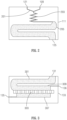
- FIG 2 is a schematic view of one embodiment of the microfluidic chip 111 of Figure 1 , which includes two inlet ports 109 and 121 and a passive mixer section that is fluidly coupled to the two inlet ports 109, 121.
- the passive mixer section includes a y-type junction part 201 that leads from the two inlet ports 109, 121 to a mixing part 203.
- the passive mixer section (parts 201 and 203) provides microfluidic mixing of the fluids introduced into the inlet ports 109, 121.
- the mixing part 203 can employ chaotic split and recombine microfluidic mixing techniques or other suitable microfluidic techniques as described in Nam-Trung Nguyen and Zhigang Wu, "Micromixers - a Review," Journal of Micromechanics and Microengineering 15, no. 2 (2005 ): Rl.
- the downstream end of part 203 extends to a reactor part 205 that is realized by a serpentine path that has larger cross-sectional diameter as compared to the channel(s) of the mixing part 203 as is evident from Figure 2 .
- the reactor part 205 allows for precipitation of asphaltenes from the mixture generated by the passive mixer section.
- the asphaltene flock is carried as a suspension in the liquid phase content of the mixture.
- the downstream end of the larger diameter serpentine path of the reactor part 205 terminates at the outlet port 125. Note that the smaller dimensions of the mixing part 203 enable more effective and rapid mixing because of shorter diffusion distances and the larger dimensions of the reactor part 205 allow asphaltene flocculates to grow to a significant size for retention by the filter section 303 as described below.
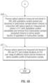
- FIG 3 is a schematic view of one embodiment of the microfluidic chip 133 of Figure 1 , which includes an inlet port 131 and an inlet flow path 301 that leads to a filter section 303.
- the filter section 303 includes a membrane filter providing microfluidic filtering that is configured to trap solid phase hydrocarbon components (i.e., the asphaltene flock) while passing the permeate - the liquid phase hydrocarbon components which include the maltenes of the hydrocarbon sample - to an outlet flow path 307 (on its bottom side) that leads to the outlet port 135.
- the inlet of the membrane filter (disposed on its top side) includes a waste flow path 309 that leads to the waste port 136.
- the waste flow path 309 and the waste port 136 allow for flushing and removal of the solid phase hydrocarbon components (i.e., the asphaltene flock) that are trapped by the membrane filter of the filter section 303 of the microfluidic chip 133.
- the flow-through optical cells 127, 137 can be realized by an optical absorbance flow cell, such as the FIAlab SMA-Z-2.5 cell with fused silica windows and a 2.5 mm optical path and a 2.0 ⁇ l internal volume available from FIAlab Instruments, Inc. of Bellevue, Washington, USA. Custom flow cells that are either machined in the chip holders or integrated directly on the chip can also be used.
- the spectrometers 129, 139 can be realized by a broadband spectrometer, such as the model HR2000+ sold commercially by OceanOptics, Inc. of Dunedin, Florida, USA.
- the broadband spectrometer can be used in conjunction with a broadband light source which can be based on a tungsten filament bulb (such as the model LS-1 light source sold commercially by OceanOptics, Inc.). Fiber optic waveguides can be used to optically couple the optical absorbance flow cell to both the broadband light source and the broadband spectrometer.
- a broadband light source which can be based on a tungsten filament bulb (such as the model LS-1 light source sold commercially by OceanOptics, Inc.).
- Fiber optic waveguides can be used to optically couple the optical absorbance flow cell to both the broadband light source and the broadband spectrometer.
- a computer processing system 145 can be programmed with suitable control logic that interfaces to the electrically-controlled pumps 105, 117, 119 via wired or wireless signal paths therebetween, that interfaces to the electrically-controlled valves 107, 141, 143 via wired or wireless signal paths therebetween, and that interfaces to the pressure sensors 113, 123 via wired or wireless signal paths therebetween.
- the computer processing system 145 can also interface to the spectrometers 129, 139 via wired or wireless signal paths therebetween.
- the control logic of the computer processing system 145 (which can be embodied in software that is loaded from persistent memory and executed in the computing platform of the computer processing system 145) is configured to control the different parts of the apparatus 101 to carry out an automated sequence of operations (workflow) that characterizes the solubility profile of a hydrocarbon sample.
- the control logic can be configured by a testing script, which is input into and executed by the computer processing system 145 to perform automatic control operations as specified by the testing script.
- the computer processing system 145 can include a graphical user interface that allows the use to specify the sequence of automatic control operations and/or the parameters (such as pressures, flow rates, and temperatures) for such automatic control operations.
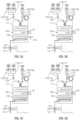
- An example of such an automated workflow is shown in Figures 4A and 4B .
- the workflow begins at 401 where the autosampler 106 (if used), the pumps 105, 117, 119 and the valves 107, 141, 143 are controlled to inject the hydrocarbon sample into the inlet port 109 of the microfluidic chip 111 and to inject solvent alone from the reservoir 118 into the inlet port 121 of the microfluidic chip 111.
- the pumping rates for the two pumps 105, 119 are configured such that the mixing section of the microfluidic chip 111 forms a mixture where the hydrocarbon sample is diluted with a predetermined concentration of the solvent.
- the volume fraction of the solvent in the mixture can possibly be at or near 80:1 for heavy oil samples or possibly at or near 40:1 for black oil samples.
- the reactor section of the microfluidic chip 111 can allow the solvent of the sample/solvent mixture produced by the mixing section to dissolve most if not all of the asphaltene content of the sample/solvent mixture (if any asphaltene content is present from the hydrocarbon sample).
- the resultant sample/solvent mixture produced by the reactor section of the microfluidic chip 111 flows downstream to the outlet port 125 and then through the flow-through optical cell 127 to the inlet port 131 of the microfluidic chip 133 for filtering.
- the fluid that moves through the filter section of the microfluidic chip 133 i.e., the "permeate" flows to the output port 135 of the microfluidic chip 133 and through the flow-through optical cell 137 to the exhaust valve 141.
- the spectrometer 129 is configured to measure an optical spectrum of the sample/solvent mixture that flows through the corresponding flow-through optical cell 127 during 401. In this manner, the spectrometer 129 measures an optical spectrum of the sample/solvent mixture output from the microfluidic chip 111 before the mixture is filtered by the microfluidic chip 133.
- the computer processing system 145 is further configured to store the optical spectrum as measured in 403.
- the spectrometer 139 is configured to measure an optical spectrum of the permeate that flows through the corresponding flow-through optical cell 137 during 401. In this manner, the spectrometer 139 measures an optical spectrum of the permeate that flows from the microfluidic chip 133.
- the computer processing system 145 is further configured to store the optical spectrum as measured in 405.
- the autosampler 106 (if used), the pumps 105, 117, 119 and the valves 107, 141, 143 are controlled to inject the hydrocarbon sample into the inlet port 109 of the microfluidic chip 111 and to inject precipitant alone from the reservoir 116 into the inlet port 121 of the microfluidic chip 111.
- the pumping rates for the two pumps 105, 117 are configured such that the mixing section of the microfluidic chip 111 forms a mixture where the hydrocarbon sample is diluted with a predetermined concentration of the precipitant.
- the volume fraction of the precipitant in the mixture can possibly be at or near 40:1 for many hydrocarbon samples.
- the reactor section of the microfluidic chip 111 can allow the precipitant of the sample/precipitant mixture produced by the mixing section to precipitate out most if not all of the asphaltene content of the sample/precipitant mixture (if any asphaltene content is present from the hydrocarbon sample).
- the resultant sample/precipitant mixture (including the precipitated solid-form asphaltene content) that is produced by the reactor section of the microfluidic chip 111 flows downstream to the outlet port 125 and then through the flow-through optical cell 127 to the inlet port 131 of the microfluidic chip 133 for filtering.
- the filtering section of the microfluidic chip 133 traps the precipitated solid-form asphaltene content and allows the permeate (i.e., the liquid phase of the sample/precipitant mixture) to pass to the outlet port 135.
- the permeate flows from the outlet port 135 and through the flow-through optical cell 137 to the exhaust valve 141.
- the spectrometer 129 is configured to measure an optical spectrum of the sample/precipitant mixture that flows through the corresponding flow-through optical cell 127 during 407. In this manner, the spectrometer 129 measures an optical spectrum of the sample/precipitant mixture output from the microfluidic chip 111 before the mixture is filtered by the microfluidic chip 133.
- the computer processing system 145 is further configured to store the optical spectrum as measured in 409.
- the spectrometer 139 is configured to measure an optical spectrum of the permeate that flows through the corresponding flow-through optical cell 137 during 407. In this manner, the spectrometer 139 measures an optical spectrum of the permeate that flows from the microfluidic chip 133.
- the computer processing system 145 is further configured to store the optical spectrum as measured in 411.
- a cleaning procedure can be executed to remove the collected asphaltenes before continuing to 413-423.
- This clean procedure can involve flowing solvent first across the membrane to waste via valve 143 and second a solvent flush of the system to the exhaust valve 141.
- the operations perform iterative operations over a range of values for a variable representing a solvent volume fraction (labeled "R").
- the iterative operations are performed over a range of values for the solvent volume fraction R that are incremented from an initial low value to a maximum threshold value.
- the value of the solvent volume fraction R is set to an initial value, such as 0.05 or 5%.
- the autosampler 106 (if used), the pumps 105, 117, 119 and the valves 107, 141, 143 are controlled to inject the hydrocarbon sample into the inlet port 109 of the microfluidic chip 111 and to inject both the precipitant from the reservoir 116 and the solvent from the reservoir 118 into the inlet port 121 of the microfluidic chip 111.
- the pumping rates for the three pumps 105, 117, 119 are configured such that the mixing section of the microfluidic chip 111 forms a mixture where the hydrocarbon sample is diluted with a combination of the solvent and the precipitant at the volumetric ratio corresponding to the solvent volume fraction R as initialized in 413.
- the concentration of the solvent/precipitant part of the mixture can also be defined by the pumping rates for the three pumps 105, 117, 119.
- the volume ratio of the solvent/precipitant part relative to the hydrocarbon sample part of the mixture is at or near 40 to 1.
- the reactor section of the microfluidic chip 111 can allow the precipitant of the sample/solvent/precipitant mixture produced by the mixing section to precipitate out asphaltene content of the sample/solvent/precipitant mixture (if any asphaltene content is present from the hydrocarbon sample).
- the sample/solvent/precipitant mixture (including any precipitated solid-form asphaltene content) that is produced by the reactor section of the microfluidic chip 111 flows downstream to the outlet port 125 and then through the flow-through optical cell 127 to the inlet port 131 of the microfluidic chip 133 for filtering.
- the filtering section of the microfluidic chip 133 traps the precipitated solid-form asphaltene content (if any) and allows the permeate (i.e., the liquid phase of the sample/solvent/precipitant mixture) to pass to the outlet port 135.
- the permeate flows from the outlet port 135 and through the flow-through optical cell 137 to the exhaust valve 141.
- the spectrometer 129 is configured to measure an optical spectrum of the sample/solvent/precipitant mixture that flows through the corresponding flow-through optical cell 127 during 415. In this manner, the spectrometer 129 measures an optical spectrum of the sample/solvent/precipitant mixture output from the microfluidic chip 111 before the mixture is filtered by the microfluidic chip 133.
- the spectrometer 139 is configured to measure an optical spectrum of the permeate that flows through the corresponding flow-through optical cell 137 during 415. In this manner, the spectrometer 139 measures an optical spectrum of the permeate that flows from the microfluidic chip 133.
- the computer processing system 145 is further configured to store the optical spectrum as measured in 419.
- the operations automatically determine whether a maximum threshold value for the solvent volume fraction R has been reached. If not, the operations continue to 423 where the value of the variable R is incremented and the operations continue to 415 to repeat the operations of 415 to 421 for the updated value of the variable R. If the maximum threshold value for the variable R has been reached, the operations continue to 425.
- the maximum threshold value for the variable R in 421 can be 0.95 or 95%, and 423 increments the value of the variable R by 0.05 or 5%.
- the iterative operations can extend over values of the solvent volume fraction R from 0.05 or 5% to 0.95 or 95% at increments of 0.05 or 5%.
- FIGS 5A, 5B, 5C, and 5D are schematic illustrations of the operations of 401-421.
- Figure 5A illustrates the operations of 401 to 405 where the mixing section of the microfluidic chip 111 forms a mixture where the hydrocarbon sample is diluted with the solvent alone.
- the reactor section of the microfluidic chip 111 can allow the solvent of the hydrocarbon sample/solvent mixture to dissolve most if not all of the asphaltene content of the sample/solvent mixture (if any asphaltene content is present from the hydrocarbon sample).
- a graphical depiction of an optical spectrum of the mixture after filtering as measured by the spectrometer 139 is also shown.
- Figure 5D illustrates the operations of 407 to 411 where the mixing section of the microfluidic chip 111 forms a mixture where the hydrocarbon sample is diluted with the precipitant alone.
- the reactor section of the microfluidic chip 111 can allow the precipitant of the sample/precipitant mixture to precipitate most if not all of the asphaltene content of the sample/precipitant mixture (if any asphaltene content is present from the hydrocarbon sample).
- a graphical depiction of an optical spectrum of the mixture after filtering as measured by the spectrometer 139 is also shown.
- Figures 5B and 5C illustrate the operations of the 413 to 423 for two values of the solvent volume fraction R.
- the mixing section of the microfluidic chip 111 forms a mixture where the hydrocarbon sample is diluted with a combination of the solvent and precipitant over a range of values for the solvent volume fraction R.
- the reactor section of the microfluidic chip 111 can allow the precipitant of the sample/precipitant mixture to precipitate asphaltene content of the sample/precipitant mixture (if any asphaltene content is present from the hydrocarbon sample) where the amount of precipitation is dependent upon the concentration of the precipitant in the mixture.
- a graphical depiction of an optical spectrum of the mixture after filtering as measured by the spectrometer 139 is also shown.
- Figure 5B corresponds to the case where the solvent volume fraction R is 0.75 or 75%
- Figure 5C corresponds to the case where the solvent volume fraction R is 0.25 or 25%.
- optical density or absorbance of the optical spectrum is at a relative maximum (or darkest in color) for the case of Figure 5A since most of the asphaltene content of the hydrocarbon sample is soluble and dissolved by the solvent, with very little precipitation of asphaltene content as well as very little filtration being performed by the microfluidic chip 133.
- the optical density or differential spectral absorbance of the optical spectrum is at a relative minimum (or lightest in color) for the case of Figure 5D since most of the asphaltene content of the hydrocarbon sample is precipitated and removed by the filtration performed by the microfluidic chip 133.
- optical density or differential spectral absorbance of the optical spectrums of the middle diagrams of Figures 5B and 5C fall between those of Figures 5A and 5D due to the partial asphaltene precipitation that arises from the corresponding values of the solvent volume fraction R and subsequent filtering performed by the microfluidic chip 133 that removes the precipitated asphaltene content.
- the computer processing system 145 processes the optical spectrum measured and stored in 405 (with the asphaltene content present and dissolved in the hydrocarbon sample/solvent mixture) in conjunction with the optical spectrum measured and stored in step 411 (with the asphaltene content precipitated and removed from the hydrocarbon sample/precipitant mixture) in order to derive the weight fraction of asphaltene in the hydrocarbon sample.
- the first term of Eq. (1) is derived from the optical spectrum of 405 and represents the contribution of both asphaltene content and the maltenes to differential spectral absorbance.
- the second term of Eq. (1) is derived from the optical spectrum of 411 and represents the contribution of the maltenes alone to differential spectral absorbance.
- the subtraction of the optical density (OD) at 800 nm in both the first and second terms is meant to reduce the error from spectral offset introduced by light scattering and from other errors in the measurements.
- the characteristic optical density or differential spectral absorbance of the asphaltene content as derived from Eq. (1) can be correlated to a weight ratio of asphaltene content in the hydrocarbon sample based upon calibration data.
- Such calibration data can define the relationship of the characteristic optical density of the asphaltene content to asphaltene content measurements in hydrocarbon samples measured using some other technique (such as a conventional gravimetric technique, in which a series of hydrocarbon samples are collected and tested).
- a correlation factor can be applied to convert the characteristic optical density of the asphaltene content to a weight ratio of asphaltene content in the hydrocarbon sample as described in Schneider, M.H., Sieben, V.J., Kharrat, A.M., and Mostowfi, F.,. "Measurement of Asphaltenes Using Optical Spectroscopy on a Microfluidic Platform," Analytical Chemistry 85, no. 10 (2013): 5153-60, doi: 10.1021/ac400495x .
- the computer processing system 145 processes the optical spectrums measured and stored in 405 and 411 and the multiple iterations of 419 over the range of different solvent volume fractions R in order to characterize the solubility of the asphaltene content of the hydrocarbon sample.
- the processing of 427 can involve deriving a characteristic optical density or differential spectral absorbance of the asphaltene content of the hydrocarbon sample over a range of different values for the solvent volume fraction R.
- the optical spectrum of 405 corresponds to the case where the solvent volume fraction R is 1 or 100% (i.e., only solvent and hydrocarbon sample)
- the optical spectrum of 411 corresponds to the case where the solvent volume fraction R is zero or 0% (i.e., only precipitant and hydrocarbon sample).
- OD R-0 (OD@600 nm Spectrum of 405 - OD@800 nm Spectrum of 405 ) - (OD@600 nm Spectrum of 411 - OD@800 nm Spectrum of 411 ).
- This Eq. (2) is identical to Eq. (1) as described above.
- the OD R values can be plotted as function of the solvent volume fraction R as shown in Figure 6 in order to present in a graphical form the solubility profile of the hydrocarbon sample.
- the first terms of Eqs. (2) - (5) are derived from the spectrum of 405 and represent the contribution of both asphaltene content and the maltenes to the OD R values.
- a function such as a line or polynomial curve or other suitable function.
- Figure 6 shows the analysis for experiments that utilize two different solvents, toluene for one case and DCM for the second case.
- toluene as the solvent
- the data points are empty squares and the fitted line crosses the x-intercept near R of 0.35.
- DCM as the solvent
- the data points are filled circles and the fitted line crosses the x-intercept near R of 0.23.
- the bottom part of Figure 6 shows two line graphs that represent the correlation function between the solvent volume fraction R fo for asphaltene flocculation onset and the critical solubility parameter ⁇ cr for two different cases.
- the upper line graph shows the correlation function between the solvent volume fraction R fo for asphaltene flocculation onset and the critical solubility parameter ⁇ cr for the case where toluene is used as the solvent and n-heptane is used as the precipitant.
- the solvent volume fraction R fo for asphaltene flocculation onset near 0.35 correlates to the critical solubility parameter ⁇ cr TOL of 16.35 MPa 1 ⁇ 2 .
- the lower line graph shows the correlation function between the solvent volume fraction R fo for asphaltene flocculation onset and the critical solubility parameter ⁇ cr for the case where DCM is used as the solvent and n-heptane is used as the precipitant.
- the solvent volume fraction R fo for asphaltene flocculation onset near 0.23 correlates to the critical solubility parameter ⁇ cr DCM of 16.45 MPa 1 ⁇ 2 .
- the measurements for both cases reveal a similar Hildebrand solubility parameter ⁇ a of 20.4 MPa 1 ⁇ 2 per Eq. (6). This value is consistent with the range of values 19-22 MPa 1 ⁇ 2 as reported in Andersen, S.I. and Speight, J.G., "Thermodynamic Models for Asphaltene Precipitation and Solubility," Journal of Petroleum Science and Engineering 53, 1999 .
- optical spectrums measured as part of 403 and 409 may not be necessary for the measurement. They are primarily used as a form of quality control. Specifically, these optical spectrums can be used to confirm that filtration was successful by noting the coloration changes before and after filtration.
- the pre-filter spectrum shows high absorbance and when asphaltenes precipitate there are large deviations to the average signal. This is caused by the flocks scattering incident light and appearing as large absorbance spikes.
- the filtered signal should be free of large variations and display a stable plateau of lower absorbance value.
- Figure 7 shows a profile of the optical density or differential spectral absorbance of a solvent-precipitant-hydrocarbon sample mixture over a range of values for the solvent volume fraction R as measured by an automated workflow employing microfluidic mixing, reacting, and filtering.
- Figure 7 also shows the mass of precipitated asphaltenes from like solvent-precipitant-hydrocarbon sample mixtures over the same range of values for the solvent volume fraction R as measured by gravimetric analysis.
- the square data points are measurements of optical density plotted using the left vertical axis and the horizontal axis representing the range of values for the solvent volume fraction R. These data points were measured by an automated workflow employing microfluidic mixing, reacting, and filtering.
- the circular data points are measurements of the mass of precipitated asphaltenes from like solvent-precipitant-hydrocarbon sample mixtures over the same range of values for the solvent volume fraction R as measured by gravimetric analysis.
- the data shows similar linear and plateau trends between the two methods within the experimental error of the techniques.
- the two methods report the flocculation point within a solvent volume fraction R fo of one percent.
- the solubility of the asphaltene content of the hydrocarbon sample is dependent on temperature.
- the temperature of the apparatus can be controlled during the workflow carried out by the apparatus 101 of Figure 1 and repeated at different temperature settings.
- Figure 8 shows the relative amount of fractional precipitation of asphaltenes over the range of solvent volume fractions R during the workflow of Figure 4 with the temperature of the apparatus 101 controlled at three different temperatures (30°C, 50°C and 70°C) for the entire workflow.
- the data points are normalized relative to the maximum value of fractional precipitation of asphaltenes with the solvent volume fraction R of 0 for the 30°C case.
- the data shows a trend as expected with the asphaltene solubility increasing (hence less fractional precipitation of asphaltenes) with an increase in temperature in agreement with the literature.
- the hydrocarbon reservoir 103 and the electrically-controlled pump 105 can hold and dispense a hydrocarbon fluid sample derived by blending quantities of different hydrocarbons or by adding one or more additives to the hydrocarbons.
- the additives can be a diluent, a dispersant, an inhibitor, or other suitable additive.
- the workflow can be used to characterize the asphaltene solubility profile of the hydrocarbon fluid sample or a resulting blend. This analysis can be useful for identifying an appropriate additive that mitigates the problems that can arise from asphaltene precipitation of the particular hydrocarbon during its production and/or transport.
- the method as described herein can be repeated over multiple iterations where the volume fraction of the hydrocarbon-containing sample relative to the precipitant and/or solvent is varied over the multiple iterations.
- Figure 9 shows an apparatus 101, not forming part of the invention, 101' for automated fluid analysis of a hydrocarbon sample similar to the apparatus 101 of Figure 1 , where the flow-through optical cell 127 and spectrometer 129 of Fig. 1 are omitted and the functions of the two microfluidic chips 111, 133 of Figure 1 are merged into one microfluidic chip 111' as shown.
- the automated microfluidic testing method of operation can provide the ability to rapidly measure asphaltene solubility parameters.
- the apparatus not forming part of the invention, can be utilized with a variety of solvent/precipitant combinations and over multiple temperature ranges, which permits frequent and more accurate acquisition of asphaltene solubility parameters.
- the automated microfluidic testing apparatus not forming part of the invention, can require minimal human intervention and can significantly reduce the testing time as well as the amount of reagent used for testing as compared to conventional approaches. Moreover, the reduction in measurement time can enable more frequent characterizations of hydrocarbon samples with blends, diluents, dispersants, inhibitors, and/or other suitable additives used in hydrocarbon fluid samples.
- solubility testing method as described herein can be used to derive experimental data that is used to calibrate a model that describes the phase behavior of asphaltene-containing petroleum fluids.
- the model can be used to perform calculations with variations in either solvent or precipitant.
- asphaltenes generally belong to a group of unknown components, the experimental data can be used to correlate or calibrate the model for engineering predictions or estimations.
- the molar volume ⁇ m of the oil mixture can be calculated from the composition of the liquid phase obtained from vapor/liquid calculations provided by a suitable equation of state or other suitable method.
- the solubility parameter ⁇ m of the mixture can also be calculated from the equation of state or other suitable method.
- all properties of asphaltenes are generally unknown - only a certain range is known as asphaltenes include a range of molecules from small polar molecules to large less polar molecules.
- the molar volume ⁇ a of asphaltene (which represents the ratio of molecular weight/density for the asphaltene) can be estimated if unknown.
- Hirschberg et al. used values of ⁇ a in the range of 1 to 4 m 3 /kmol.
- the solubility parameter of asphaltene ⁇ a can also be estimated if unknown.
- the experimental data derived from the solubility testing method as described herein, which measures the solubility of asphaltene in a solvent-precipitant fluid of varying solvent volume fraction, can be used to estimate the molar volume ⁇ a and/or the solubility parameter of asphaltene ⁇ a if unknown.
- a correlation procedure can be used that varies molar volume of a number of experimental points and calculates the corresponding solubility parameter of asphaltene ⁇ a over a set of solvent-precipitant fluids of varying solvent volume fraction. Both the molar volume and the solubility parameter of the solvent can be used as input parameters while estimating the solubility parameter of the asphaltenes in solution.
- An example of the results of this correlation procedure is shown in Figure 10 .
- the correlation procedure followed the procedure outlined in Andersen and Stenby, "Thermodynamics of Asphaltene Precipitation and Dissolution Investigation of Temperature and Solvent Effects," Fuel Science and Technology International, Vol. 14, Iss. 1-2, 1996 .
- the results of the correlation procedure will yield a common point of intersection which then means one can model the system with one single pair of values for the asphaltene molar volume ⁇ a and the solubility parameter of asphaltene ⁇ a .
- any arbitrary value of asphaltene molar volume within the range of results (such as a value of 1000 cc/mole) can be selected.
- the model is in principle correct as it shows that as the solvent gets stronger only material with a higher solubility parameter precipitates.
- the modeling is initialized by calculating the solubility parameter of asphaltene ⁇ a based on the difference between the amount of precipitated asphaltene in the precipitant alone (e.g., heptane) and the amount of precipitated asphaltene in a solvent/precipitant (e.g., toluene/heptane) mixture.
- Figure 11 shows the results (labeled "Series 1 ”) of such calculations over the set of solvent-precipitant fluids of varying solvent volume fraction.
- Figure 11 also shows a best fit function (in this case, a line labeled "Linear Fit (Series 1)") that relates the solubility parameter of asphaltene ⁇ a to the solvent volume fraction of the mixture.
- the model can also be extended to relate the solubility parameter of asphaltenes ⁇ a to spectral absorbance (as measured by a spectrometer) over the set of solvent volume fractions. The spectral absorbance as predicted by the model can be compared to experimental data and is directly related to the precipitated amount of asphaltenes at the given conditions.
- Figure 12 shows a measure of differential spectral absorbance as predicted by the model (labeled "Model (correlated)") and corresponding experimental data measured by the test method as described above over a set of solvent volume fractions.
- the molar volume of asphaltenes is set to 1000 cc/mole in the model.
- thermodynamic models that describe the phase behavior of asphaltene-containing hydrocarbon fluids.
- a more complex model that treats asphaltenes as a molecular weight distribution with an independent solubility parameter (calibrated to density data if available from a crude oil characterization) is described in Sabbagh, O., Akbarzadeh, K., Badamchi-Zadeh, A., Svrcek, W.Y., and Yarranton, H.W., "Applying the PR-EoS to Asphaltene Precipitation from n-Alkane Diluted Heavy Oils and Bitumens," Energy & Fuels 2006, 20, pp. 625-634 .
- thermodynamic models that describe the phase behavior of asphaltene-containing petroleum fluids can employ parameters that relate to the size of the asphaltene molecule, Hamaker constants for asphaltenes, and association energy parameters, all of which can be calibrated by the experimental data derived from the solubility testing method as described herein.
- thermodynamic models can be used to estimate diluent effect, blending of different oils, and the effects of injection gas or other fluids on asphaltene stability and yield. These thermodynamic models require a solubility parameter for asphaltenes, which can be estimated for a particular oil using the method as described herein.
- OCM oil compatibility model
- the critical solubility parameter ⁇ cr at which asphaltenes will reach incipient flocculation can be used to derive a flocculation solubility parameter called the insolubility number and the solubility parameter of the oil is called the solubility blending number.
- the criterion for oil compatibility is that the volume average solubility blending number of the mixture is higher than the insolubility number of any asphaltene-containing component in the mixture.
Landscapes
- Chemical & Material Sciences (AREA)
- Health & Medical Sciences (AREA)
- Life Sciences & Earth Sciences (AREA)
- Physics & Mathematics (AREA)
- Analytical Chemistry (AREA)
- General Health & Medical Sciences (AREA)
- Biochemistry (AREA)
- General Physics & Mathematics (AREA)
- Immunology (AREA)
- Pathology (AREA)
- Chemical Kinetics & Catalysis (AREA)
- Engineering & Computer Science (AREA)
- Dispersion Chemistry (AREA)
- Food Science & Technology (AREA)
- Medicinal Chemistry (AREA)
- Spectroscopy & Molecular Physics (AREA)
- Plasma & Fusion (AREA)
- Hematology (AREA)
- Clinical Laboratory Science (AREA)
- General Chemical & Material Sciences (AREA)
- Oil, Petroleum & Natural Gas (AREA)
- Remote Sensing (AREA)
- Environmental & Geological Engineering (AREA)
- Geology (AREA)
- General Life Sciences & Earth Sciences (AREA)
- Investigating Or Analysing Materials By Optical Means (AREA)
Claims (15)
- Verfahren zum Analysieren der Löslichkeit von Asphaltenen einer Kohlenwasserstofffluidprobe unter Verwendung eines Lösungsmittelfluids, das Asphaltene löst, und eines Fällungsmittelfluids, das Asphaltene ausfällt, und unter Verwendung von optischer Spektroskopie, dadurch gekennzeichnet, dass das Verfahren umfasst:i) Durchführen von mikrofluidischen Mischvorgängen, die eine Mischung bilden, welche die Kohlenwasserstofffluidprobe, das Lösungsmittelfluid und das Fällungsmittelfluid umfasst;ii) Verwenden von mikrofluidischen Prozessen, die in der Ausfällung von Asphaltenen aus der aus i) resultierenden Mischung resultieren;iii) Durchführen von mikrofluidischen Filtervorgängen, die ausgefällte Asphaltene aus der aus ii) resultierenden Mischung entfernen und dabei Permeat abgeben;iv) Durchführen einer optischen Spektroskopie mit dem aus iii) resultierenden Permeat; undv) Wiederholen der Vorgänge von i) - iv) über eine Anzahl von Iterationen, die die Menge von Lösungsmittelfluid bezogen auf das Fällungsmittelfluid in der aus i) resultierenden Mischung variieren und dadurch eine variierende fraktionierte Ausfällung von Asphaltenen während ii) der Iterationen bewirken.
- Verfahren gemäß Anspruch 1, ferner umfassend:vi) Durchführen von mikrofluidischen Mischvorgängen, die eine Mischung bilden, welche die Kohlenwasserstofffluidprobe und das Lösungsmittelfluid, nicht aber das Fällungsmittelfluid umfasst;vii) Verwenden von mikrofluidischen Prozessen, die in der Ausfällung von Asphaltenen aus der aus vi) resultierenden Mischung resultieren;viii) Durchführen von mikrofluidischen Filtervorgängen, die ausgefällte Asphaltene aus der aus vii) resultierenden Mischung, falls vorliegend, entfernen und dabei Permeat abgeben; undix) Durchführen einer optischen Spektroskopie mit dem aus viii) resultierenden Permeat.
- Verfahren gemäß Anspruch 2, ferner umfassendx) Durchführen von mikrofluidischen Mischvorgängen, die eine Mischung bilden, welche die Kohlenwasserstofffluidprobe und das Fällungsmittelfluid, nicht aber das Lösungsmittelfluid umfasst;xi) Verwenden von mikrofluidischen Reaktionen, die in der Ausfällung von Asphaltenen aus der aus x) resultierenden Mischung resultieren;xii) Durchführen von mikrofluidischen Filtervorgängen, die ausgefällte Asphaltene aus der aus xi) resultierenden Mischung entfernen und dabei Permeat abgeben; undxiii) Durchführen einer optischen Spektroskopie mit dem aus xii) resultierenden Permeat.
- Verfahren gemäß einem der vorhergehenden Ansprüche, wobei die mikrofluidischen Mischvorgänge von i), die mikrofluidischen Prozesse von ii) und die mikrofluidischen Filtervorgänge von iii) durch wenigstens einen mikrofluidischen Chip durchgeführt werden.
- Verfahren gemäß Anspruch 4, wobei:der wenigstens eine mikrofluidische Chip einen ersten und einen zweiten Eingangsanschluss umfasst, die strömungstechnisch mit einem Mischerabschnitt gekoppelt sind;der erste Eingangsanschluss dazu ausgelegt ist, dem Mischerabschnitt eine Kombination aus dem Lösungsmittelfluid und dem Fällungsmittelfluid zur Verwendung in Verbindung mit den mikrofluidischen Mischvorgängen von i) zuzuführen; undder zweite Eingangsanschluss dazu ausgelegt ist, dem Mischerabschnitt die Kohlenwasserstofffluidprobe zur Verwendung in Verbindung mit den mikrofluidischen Mischvorgängen von i) zuzuführen.
- Verfahren gemäß Anspruch 5, wobei der wenigstens eine mikrofluidische Chip einen Reaktorabschnitt umfasst, der strömungstechnisch nach dem Mischerabschnitt angeschlossen ist.
- Verfahren gemäß Anspruch 6, wobei der wenigstens eine mikrofluidische Chip einen Membranfilterabschnitt umfasst, der strömungstechnisch nach dem Reaktorabschnitt angeschlossen ist, wobei der Membranfilterabschnitt zu sowohl einem Abfallanschluss als auch einem Auslassanschluss führt.
- Verfahren gemäß einem der vorhergehenden Ansprüche, wobei die Kohlenwasserstofffluidprobe ausgewählt wird aus der Gruppe bestehend aus einer Rohölprobe, einer Mischung verschiedener Rohöle, einem oder mehreren mit Rohöl kombinierten Additiven, Kohleverflüssigungsprodukten, Mischungen aus Naphtha und Bitumen, Mischungen aus Raffinerierückständen und Verdünnungsmitteln, und Straßenasphalt.
- Verfahren gemäß einem der vorhergehenden Ansprüche, ferner umfassend:Ableiten und Speichern einer optischen Spektrummessung während der optischen Spektroskopie von iv) für jede gegebene Iteration; undVerarbeiten der gespeicherten optischen Spektren, um experimentelle Daten bezogen auf die Löslichkeit von Asphaltenen in der Kohlenwasserstofffluidprobe abzuleiten.
- Verfahren gemäß Anspruch 9, wobei das Verarbeiten umfasst, einen Lösungsmittelvolumenanteil für das Einsetzen der Asphaltenausflockung zu identifizieren.
- Verfahren nach Anspruch 9 oder Anspruch 10, wobei die Verarbeitung der gespeicherten optischen Spektren umfasst:Berechnen mehrerer charakteristischer optischer Dichten, die Lösungsmittelvolumenanteilen für die Permeate zugeordnet sind, die sich aus iii) in jeder gegebenen Iteration ergeben;Identifizieren einer Funktion, die einer Anzahl der mehreren charakteristischen optischen Dichten entspricht; undBerechnen eines Parameters oder einer Funktion bezogen auf die Löslichkeit von Asphaltenen der Kohlenwasserstofffluidprobe basierend auf einem Parameter der Funktion.
- Verfahren gemäß Anspruch 11, wobei jede der gegebenen mehreren charakteristischen optischen Dichten berechnet wird durch Subtraktion einer optischen Dichtekomponente, die für die Maltene der Kohlenwasserstofffluidprobe charakteristisch ist, von einer optischen Dichtekomponente, die für das Permeat charakteristisch ist, das aus iii) in einer gegebenen Iteration resultiert.
- Verfahren gemäß Anspruch 12, wobei:die optische Dichtekomponente, die für die Maltene der Kohlenwasserstofffluidprobe charakteristisch ist aus optischen Dichtemessungen bei mehreren verschiedenen Wellenlängen abgeleitet wird; unddie optische Dichtekomponente, die für das Permeat charakteristisch ist, das aus iii) in einer gegebenen Iteration resultiert, aus optischen Dichtemessungen bei mehreren verschiedenen Wellenlängen abgeleitet wird.
- Verfahren gemäß Anspruch 11,
wobei der auf die Löslichkeit von Asphaltenen der Kohlenwasserstofffluidprobe bezogene Parameter, ein kritischer Löslichkeitsparameter δcr ist. - Verfahren gemäß Anspruch 9,
ferner umfassend Verwenden der Versuchsmessdaten, um ein Modell zu kalibrieren, das das Phasenverhalten von asphaltenhaltigen Kohlenwasserstofffluiden beschreibt.
Applications Claiming Priority (2)
| Application Number | Priority Date | Filing Date | Title |
|---|---|---|---|
| US201361864987P | 2013-08-12 | 2013-08-12 | |
| PCT/US2014/039800 WO2015023343A1 (en) | 2013-08-12 | 2014-05-28 | Automated method and apparatus to characterize solubility of asphaltenes of a hydrocarbon fluid sample utilizing microfluidics |
Publications (3)
| Publication Number | Publication Date |
|---|---|
| EP3033618A1 EP3033618A1 (de) | 2016-06-22 |
| EP3033618A4 EP3033618A4 (de) | 2017-04-12 |
| EP3033618B1 true EP3033618B1 (de) | 2024-07-31 |
Family
ID=52468565
Family Applications (1)
| Application Number | Title | Priority Date | Filing Date |
|---|---|---|---|
| EP14836050.6A Active EP3033618B1 (de) | 2013-08-12 | 2014-05-28 | Automatisiertes verfahren zur charakterisierung der löslichkeit von asphaltenen einer kohlenwasserstoffflüssigkeitsprobe mittels mikrofluidik |
Country Status (5)
| Country | Link |
|---|---|
| US (1) | US10031122B2 (de) |
| EP (1) | EP3033618B1 (de) |
| AU (1) | AU2014307068A1 (de) |
| CA (1) | CA2911183C (de) |
| WO (1) | WO2015023343A1 (de) |
Families Citing this family (17)
| Publication number | Priority date | Publication date | Assignee | Title |
|---|---|---|---|---|
| US9791359B2 (en) * | 2013-12-06 | 2017-10-17 | Instituto Mexican Del Petroleo | Process for determining the incompatibility of mixtures containing heavy and light crudes |
| US9678002B2 (en) * | 2014-10-29 | 2017-06-13 | Chevron U.S.A. Inc. | Method and system for NIR spectroscopy of mixtures to evaluate composition of components of the mixtures |
| WO2016163990A1 (en) * | 2015-04-07 | 2016-10-13 | Schlumberger Canada Limited | Method of predicting the concentration of asphaltenes using a first precipitant and correlation back to an asphaltene concentration measurement using a second precipitant |
| US11035839B2 (en) | 2015-06-08 | 2021-06-15 | Schlumberger Technology Corporation | Automated method and apparatus for measuring saturate, aromatic, resin, and asphaltene fractions using microfluidics and spectroscopy |
| WO2016209248A1 (en) * | 2015-06-26 | 2016-12-29 | Schlumberger Canada Limited | Microfluidic method for detection of fines, waxes, and asphaltenes in oil |
| US9689858B2 (en) * | 2015-10-21 | 2017-06-27 | Schlumberger Technology Corporation | Method and apparatus for measuring asphaltene onset conditions and yields of crude oils |
| US10281397B2 (en) | 2015-11-10 | 2019-05-07 | Schlumberger Technology Corporation | Optical sensors using surface plasmon resonance to determine at least one property relating to phase change of a hydrocarbon-based analyte |
| US10527536B2 (en) * | 2016-02-05 | 2020-01-07 | Baker Hughes, A Ge Company, Llc | Method of determining the stability reserve and solubility parameters of a process stream containing asphaltenes by joint use of turbidimetric method and refractive index |
| CN108603875B (zh) * | 2016-02-05 | 2021-09-07 | 通用电气(Ge)贝克休斯有限责任公司 | 通过联合使用比浊法和折射率确定含有沥青质的工艺流的稳定性储备和溶解度参数的方法 |
| US10065187B2 (en) * | 2016-02-12 | 2018-09-04 | Schlumberger Technology Corporation | Centrifugal platform and device for rapid analysis of oilfield fluids |
| US10254216B2 (en) | 2016-06-30 | 2019-04-09 | Schlumberger Technology Corporation | Systems, methods and apparatus for analysis of reservoir fluids using surface plasmon resonance |
| EP3612837B1 (de) * | 2017-04-21 | 2023-03-29 | Baker Hughes Holdings LLC | Verfahren zur bestimmung der stabilitätsreserve und löslichkeitsparameter eines prozessstromes mit asphaltenen durch gemeinsame verwendung eines turbidimetrischen verfahrens und brechungsindex |
| CA3053995A1 (en) * | 2019-01-08 | 2020-07-08 | Interface Fluidics Ltd. | Microfluidic devices and systems, and methods for operating microfluidic devices and systems |
| WO2021253112A1 (en) * | 2020-06-15 | 2021-12-23 | Interface Fluidics Ltd. | Microfluidic devices, systems, and methods |
| EP4388295A1 (de) * | 2021-12-29 | 2024-06-26 | Andrew Alliance S.A. | Probenextraktionssystem und -verfahren |
| CN115238986B (zh) * | 2022-07-19 | 2023-09-26 | 西南石油大学 | 一种沥青分布预测方法、装置及计算机可读存储介质 |
| CN116539567A (zh) * | 2023-06-05 | 2023-08-04 | 西南石油大学 | 微型沥青质含量实时在线检测装置及方法 |
Family Cites Families (5)
| Publication number | Priority date | Publication date | Assignee | Title |
|---|---|---|---|---|
| CA2437652C (en) * | 2001-02-05 | 2009-12-29 | The University Of Wyoming Research Corporation | Automated flocculation titrimeter system |
| US6839137B2 (en) | 2002-07-19 | 2005-01-04 | Exxonmobil Research And Engineering Company | Asphaltene aggregation in petroleum oil mixtures determined by small angle light scattering |
| US20110066441A1 (en) * | 2009-09-14 | 2011-03-17 | Chevron U.S.A. Inc. | Method for predicting reactivity of a hydrocarbon-containing feedstock for hydroprocessing |
| US20120160015A1 (en) * | 2010-03-11 | 2012-06-28 | Chevron U.S.A. Inc. | Methods for predicting fouling tendencies of hydrocarbon containing feedstocks |
| US8269961B2 (en) * | 2010-05-31 | 2012-09-18 | Schlumberger Technology Corporation | System and method for determining the asphaltene content of crude oil |
-
2014
- 2014-05-28 WO PCT/US2014/039800 patent/WO2015023343A1/en not_active Ceased
- 2014-05-28 US US14/893,016 patent/US10031122B2/en active Active
- 2014-05-28 CA CA2911183A patent/CA2911183C/en active Active
- 2014-05-28 EP EP14836050.6A patent/EP3033618B1/de active Active
- 2014-05-28 AU AU2014307068A patent/AU2014307068A1/en not_active Abandoned
Also Published As
| Publication number | Publication date |
|---|---|
| WO2015023343A1 (en) | 2015-02-19 |
| EP3033618A1 (de) | 2016-06-22 |
| CA2911183A1 (en) | 2015-02-19 |
| AU2014307068A1 (en) | 2015-11-19 |
| EP3033618A4 (de) | 2017-04-12 |
| CA2911183C (en) | 2021-07-13 |
| US20160097757A1 (en) | 2016-04-07 |
| US10031122B2 (en) | 2018-07-24 |
Similar Documents
| Publication | Publication Date | Title |
|---|---|---|
| US10031122B2 (en) | Automated method and apparatus to characterize solubility of asphaltenes of a hydrocarbon fluid sample utilizing microfluidics | |
| US11906501B2 (en) | Automated method and apparatus for measuring saturate, aromatic, resin, and asphaltene fractions using microfluidics and spectroscopy | |
| Guzman et al. | Methods for determining asphaltene stability in crude oils | |
| US8269961B2 (en) | System and method for determining the asphaltene content of crude oil | |
| US6662116B2 (en) | Method for analyzing an unknown material as a blend of known materials calculated so as to match certain analytical data and predicting properties of the unknown based on the calculated blend | |
| US10677775B2 (en) | Microfluidic method for detection of fines, waxes, and asphaltenes in oil | |
| US9068962B2 (en) | Method and apparatus for determining asphaltene yield and flocculation point of crude oil | |
| Sieben et al. | Asphaltenes yield curve measurements on a microfluidic platform | |
| Tharanivasan et al. | Measurement and modeling of asphaltene precipitation from crude oil blends | |
| Sieben et al. | Microfluidic approach for evaluating the solubility of crude oil asphaltenes | |
| Ramos-Pallares et al. | Extending the Modified Regular Solution model to predict component partitioning to the asphaltene-rich phase | |
| US9678002B2 (en) | Method and system for NIR spectroscopy of mixtures to evaluate composition of components of the mixtures | |
| Romero Yanes et al. | Phase behavior for crude oil and methane mixtures: crude oil property comparison | |
| Abutaqiya et al. | Aromatic Ring Index (ARI): A characterization factor for nonpolar hydrocarbons from molecular weight and refractive index | |
| Romero Yanes et al. | Phase behavior investigation of a live presalt crude oil from short-wave infrared observation, acoustic wave sensing, and equation of state modeling | |
| Romero Yanes et al. | Measurement of fluid phase equilibria for high gas ratio mixtures of carbon dioxide, methane, and Brazilian presalt crude oil | |
| Ramos-Pallares et al. | Application of the modified regular solution model to crude oils characterized from a distillation assay | |
| Sieben et al. | Novel measurement of asphaltene content in oil using microfluidic technology | |
| Jennings et al. | Asphaltene stability analyses for optimizing field treatment programs | |
| Niño et al. | FTIR-ATR predictive model for determination of asphaltene solubility class index (ASCI) based on partial least-squares regression (PLS-R) | |
| US20160290919A1 (en) | Spectral analysis through model switching | |
| US10379100B2 (en) | Method of predicting the concentration of asphaltenes using a first precipitant and correlation back to an asphaltene concentration measurement using a second precipitant | |
| Ahmed et al. | Real-Time Downhole Fluid Analysis and Sampling with a New Optical Composition Analysis Sensor: A Case Study from Kuwait Heavy Oil Formation | |
| US20250003946A1 (en) | Estimating molecular weight of hydrocarbons |
Legal Events
| Date | Code | Title | Description |
|---|---|---|---|
| PUAI | Public reference made under article 153(3) epc to a published international application that has entered the european phase |
Free format text: ORIGINAL CODE: 0009012 |
|
| 17P | Request for examination filed |
Effective date: 20160223 |
|
| AK | Designated contracting states |
Kind code of ref document: A1 Designated state(s): AL AT BE BG CH CY CZ DE DK EE ES FI FR GB GR HR HU IE IS IT LI LT LU LV MC MK MT NL NO PL PT RO RS SE SI SK SM TR |
|
| AX | Request for extension of the european patent |
Extension state: BA ME |
|
| RIN1 | Information on inventor provided before grant (corrected) |
Inventor name: SIEBEN, VINCENT Inventor name: ANDERSEN, SIMON IVAR Inventor name: MOSTOWFI, FARSHID Inventor name: KHARRAT, ABDEL M. |
|
| DAX | Request for extension of the european patent (deleted) | ||
| RIC1 | Information provided on ipc code assigned before grant |
Ipc: G01N 21/25 20060101ALI20170118BHEP Ipc: G01N 1/28 20060101ALI20170118BHEP Ipc: G01N 33/24 20060101ALI20170118BHEP Ipc: G01N 33/42 20060101AFI20170118BHEP |
|
| RIC1 | Information provided on ipc code assigned before grant |
Ipc: G01N 1/28 20060101ALI20170202BHEP Ipc: G01N 33/42 20060101AFI20170202BHEP Ipc: G01N 21/25 20060101ALI20170202BHEP Ipc: G01N 33/24 20060101ALI20170202BHEP |
|
| A4 | Supplementary search report drawn up and despatched |
Effective date: 20170310 |
|
| RIC1 | Information provided on ipc code assigned before grant |
Ipc: G01N 33/24 20060101ALI20170306BHEP Ipc: G01N 21/25 20060101ALI20170306BHEP Ipc: G01N 1/28 20060101ALI20170306BHEP Ipc: G01N 33/42 20060101AFI20170306BHEP |
|
| RIC1 | Information provided on ipc code assigned before grant |
Ipc: G01N 1/40 20060101AFI20200908BHEP Ipc: B01L 3/00 20060101ALI20200908BHEP Ipc: B01F 13/00 20060101ALI20200908BHEP Ipc: G01N 1/38 20060101ALN20200908BHEP Ipc: G01N 33/28 20060101ALN20200908BHEP Ipc: G01N 21/82 20060101ALI20200908BHEP Ipc: B01F 5/06 20060101ALI20200908BHEP |
|
| STAA | Information on the status of an ep patent application or granted ep patent |
Free format text: STATUS: EXAMINATION IS IN PROGRESS |
|
| RIC1 | Information provided on ipc code assigned before grant |
Ipc: G01N 1/38 20060101ALN20201021BHEP Ipc: G01N 33/28 20060101ALN20201021BHEP Ipc: B01F 13/00 20060101ALI20201021BHEP Ipc: B01F 5/06 20060101ALI20201021BHEP Ipc: G01N 21/82 20060101ALI20201021BHEP Ipc: G01N 1/40 20060101AFI20201021BHEP Ipc: B01L 3/00 20060101ALI20201021BHEP |
|
| 17Q | First examination report despatched |
Effective date: 20201120 |
|
| REG | Reference to a national code |
Ref country code: DE Ref legal event code: R079 Free format text: PREVIOUS MAIN CLASS: G01N0033420000 Ipc: G01N0001400000 Ref document number: 602014090611 Country of ref document: DE |
|
| RIC1 | Information provided on ipc code assigned before grant |
Ipc: G01N 33/28 20060101ALN20230201BHEP Ipc: G01N 1/38 20060101ALN20230201BHEP Ipc: B01F 33/30 20220101ALI20230201BHEP Ipc: B01F 25/433 20220101ALI20230201BHEP Ipc: G01N 21/82 20060101ALI20230201BHEP Ipc: B01L 3/00 20060101ALI20230201BHEP Ipc: G01N 1/40 20060101AFI20230201BHEP |
|
| GRAP | Despatch of communication of intention to grant a patent |
Free format text: ORIGINAL CODE: EPIDOSNIGR1 |
|
| STAA | Information on the status of an ep patent application or granted ep patent |
Free format text: STATUS: GRANT OF PATENT IS INTENDED |
|
| INTG | Intention to grant announced |
Effective date: 20240405 |
|
| GRAS | Grant fee paid |
Free format text: ORIGINAL CODE: EPIDOSNIGR3 |
|
| GRAA | (expected) grant |
Free format text: ORIGINAL CODE: 0009210 |
|
| STAA | Information on the status of an ep patent application or granted ep patent |
Free format text: STATUS: THE PATENT HAS BEEN GRANTED |
|
| AK | Designated contracting states |
Kind code of ref document: B1 Designated state(s): AL AT BE BG CH CY CZ DE DK EE ES FI FR GB GR HR HU IE IS IT LI LT LU LV MC MK MT NL NO PL PT RO RS SE SI SK SM TR |
|
| REG | Reference to a national code |
Ref country code: CH Ref legal event code: EP Ref country code: GB Ref legal event code: FG4D |
|
| REG | Reference to a national code |
Ref country code: DE Ref legal event code: R096 Ref document number: 602014090611 Country of ref document: DE |
|
| REG | Reference to a national code |
Ref country code: IE Ref legal event code: FG4D |
|
| REG | Reference to a national code |
Ref country code: LT Ref legal event code: MG9D |
|
| REG | Reference to a national code |
Ref country code: NL Ref legal event code: MP Effective date: 20240731 |
|
| PG25 | Lapsed in a contracting state [announced via postgrant information from national office to epo] |
Ref country code: PT Free format text: LAPSE BECAUSE OF FAILURE TO SUBMIT A TRANSLATION OF THE DESCRIPTION OR TO PAY THE FEE WITHIN THE PRESCRIBED TIME-LIMIT Effective date: 20241202 |
|
| REG | Reference to a national code |
Ref country code: AT Ref legal event code: MK05 Ref document number: 1708902 Country of ref document: AT Kind code of ref document: T Effective date: 20240731 |
|
| PG25 | Lapsed in a contracting state [announced via postgrant information from national office to epo] |
Ref country code: PT Free format text: LAPSE BECAUSE OF FAILURE TO SUBMIT A TRANSLATION OF THE DESCRIPTION OR TO PAY THE FEE WITHIN THE PRESCRIBED TIME-LIMIT Effective date: 20241202 |
|
| PG25 | Lapsed in a contracting state [announced via postgrant information from national office to epo] |
Ref country code: FI Free format text: LAPSE BECAUSE OF FAILURE TO SUBMIT A TRANSLATION OF THE DESCRIPTION OR TO PAY THE FEE WITHIN THE PRESCRIBED TIME-LIMIT Effective date: 20240731 Ref country code: NL Free format text: LAPSE BECAUSE OF FAILURE TO SUBMIT A TRANSLATION OF THE DESCRIPTION OR TO PAY THE FEE WITHIN THE PRESCRIBED TIME-LIMIT Effective date: 20240731 Ref country code: PL Free format text: LAPSE BECAUSE OF FAILURE TO SUBMIT A TRANSLATION OF THE DESCRIPTION OR TO PAY THE FEE WITHIN THE PRESCRIBED TIME-LIMIT Effective date: 20240731 Ref country code: GR Free format text: LAPSE BECAUSE OF FAILURE TO SUBMIT A TRANSLATION OF THE DESCRIPTION OR TO PAY THE FEE WITHIN THE PRESCRIBED TIME-LIMIT Effective date: 20241101 |
|
| PG25 | Lapsed in a contracting state [announced via postgrant information from national office to epo] |
Ref country code: BG Free format text: LAPSE BECAUSE OF FAILURE TO SUBMIT A TRANSLATION OF THE DESCRIPTION OR TO PAY THE FEE WITHIN THE PRESCRIBED TIME-LIMIT Effective date: 20240731 |
|
| PG25 | Lapsed in a contracting state [announced via postgrant information from national office to epo] |
Ref country code: LV Free format text: LAPSE BECAUSE OF FAILURE TO SUBMIT A TRANSLATION OF THE DESCRIPTION OR TO PAY THE FEE WITHIN THE PRESCRIBED TIME-LIMIT Effective date: 20240731 |
|
| PG25 | Lapsed in a contracting state [announced via postgrant information from national office to epo] |
Ref country code: AT Free format text: LAPSE BECAUSE OF FAILURE TO SUBMIT A TRANSLATION OF THE DESCRIPTION OR TO PAY THE FEE WITHIN THE PRESCRIBED TIME-LIMIT Effective date: 20240731 Ref country code: IS Free format text: LAPSE BECAUSE OF FAILURE TO SUBMIT A TRANSLATION OF THE DESCRIPTION OR TO PAY THE FEE WITHIN THE PRESCRIBED TIME-LIMIT Effective date: 20241130 |
|
| PG25 | Lapsed in a contracting state [announced via postgrant information from national office to epo] |
Ref country code: HR Free format text: LAPSE BECAUSE OF FAILURE TO SUBMIT A TRANSLATION OF THE DESCRIPTION OR TO PAY THE FEE WITHIN THE PRESCRIBED TIME-LIMIT Effective date: 20240731 |
|
| PG25 | Lapsed in a contracting state [announced via postgrant information from national office to epo] |
Ref country code: ES Free format text: LAPSE BECAUSE OF FAILURE TO SUBMIT A TRANSLATION OF THE DESCRIPTION OR TO PAY THE FEE WITHIN THE PRESCRIBED TIME-LIMIT Effective date: 20240731 Ref country code: RS Free format text: LAPSE BECAUSE OF FAILURE TO SUBMIT A TRANSLATION OF THE DESCRIPTION OR TO PAY THE FEE WITHIN THE PRESCRIBED TIME-LIMIT Effective date: 20241031 |
|
| PG25 | Lapsed in a contracting state [announced via postgrant information from national office to epo] |
Ref country code: RS Free format text: LAPSE BECAUSE OF FAILURE TO SUBMIT A TRANSLATION OF THE DESCRIPTION OR TO PAY THE FEE WITHIN THE PRESCRIBED TIME-LIMIT Effective date: 20241031 Ref country code: PL Free format text: LAPSE BECAUSE OF FAILURE TO SUBMIT A TRANSLATION OF THE DESCRIPTION OR TO PAY THE FEE WITHIN THE PRESCRIBED TIME-LIMIT Effective date: 20240731 Ref country code: NL Free format text: LAPSE BECAUSE OF FAILURE TO SUBMIT A TRANSLATION OF THE DESCRIPTION OR TO PAY THE FEE WITHIN THE PRESCRIBED TIME-LIMIT Effective date: 20240731 Ref country code: LV Free format text: LAPSE BECAUSE OF FAILURE TO SUBMIT A TRANSLATION OF THE DESCRIPTION OR TO PAY THE FEE WITHIN THE PRESCRIBED TIME-LIMIT Effective date: 20240731 Ref country code: IS Free format text: LAPSE BECAUSE OF FAILURE TO SUBMIT A TRANSLATION OF THE DESCRIPTION OR TO PAY THE FEE WITHIN THE PRESCRIBED TIME-LIMIT Effective date: 20241130 Ref country code: HR Free format text: LAPSE BECAUSE OF FAILURE TO SUBMIT A TRANSLATION OF THE DESCRIPTION OR TO PAY THE FEE WITHIN THE PRESCRIBED TIME-LIMIT Effective date: 20240731 Ref country code: GR Free format text: LAPSE BECAUSE OF FAILURE TO SUBMIT A TRANSLATION OF THE DESCRIPTION OR TO PAY THE FEE WITHIN THE PRESCRIBED TIME-LIMIT Effective date: 20241101 Ref country code: FI Free format text: LAPSE BECAUSE OF FAILURE TO SUBMIT A TRANSLATION OF THE DESCRIPTION OR TO PAY THE FEE WITHIN THE PRESCRIBED TIME-LIMIT Effective date: 20240731 Ref country code: ES Free format text: LAPSE BECAUSE OF FAILURE TO SUBMIT A TRANSLATION OF THE DESCRIPTION OR TO PAY THE FEE WITHIN THE PRESCRIBED TIME-LIMIT Effective date: 20240731 Ref country code: BG Free format text: LAPSE BECAUSE OF FAILURE TO SUBMIT A TRANSLATION OF THE DESCRIPTION OR TO PAY THE FEE WITHIN THE PRESCRIBED TIME-LIMIT Effective date: 20240731 Ref country code: AT Free format text: LAPSE BECAUSE OF FAILURE TO SUBMIT A TRANSLATION OF THE DESCRIPTION OR TO PAY THE FEE WITHIN THE PRESCRIBED TIME-LIMIT Effective date: 20240731 |
|
| PG25 | Lapsed in a contracting state [announced via postgrant information from national office to epo] |
Ref country code: SM Free format text: LAPSE BECAUSE OF FAILURE TO SUBMIT A TRANSLATION OF THE DESCRIPTION OR TO PAY THE FEE WITHIN THE PRESCRIBED TIME-LIMIT Effective date: 20240731 Ref country code: DK Free format text: LAPSE BECAUSE OF FAILURE TO SUBMIT A TRANSLATION OF THE DESCRIPTION OR TO PAY THE FEE WITHIN THE PRESCRIBED TIME-LIMIT Effective date: 20240731 Ref country code: RO Free format text: LAPSE BECAUSE OF FAILURE TO SUBMIT A TRANSLATION OF THE DESCRIPTION OR TO PAY THE FEE WITHIN THE PRESCRIBED TIME-LIMIT Effective date: 20240731 |
|
| PG25 | Lapsed in a contracting state [announced via postgrant information from national office to epo] |
Ref country code: EE Free format text: LAPSE BECAUSE OF FAILURE TO SUBMIT A TRANSLATION OF THE DESCRIPTION OR TO PAY THE FEE WITHIN THE PRESCRIBED TIME-LIMIT Effective date: 20240731 |
|
| PG25 | Lapsed in a contracting state [announced via postgrant information from national office to epo] |
Ref country code: CZ Free format text: LAPSE BECAUSE OF FAILURE TO SUBMIT A TRANSLATION OF THE DESCRIPTION OR TO PAY THE FEE WITHIN THE PRESCRIBED TIME-LIMIT Effective date: 20240731 |
|
| PG25 | Lapsed in a contracting state [announced via postgrant information from national office to epo] |
Ref country code: SK Free format text: LAPSE BECAUSE OF FAILURE TO SUBMIT A TRANSLATION OF THE DESCRIPTION OR TO PAY THE FEE WITHIN THE PRESCRIBED TIME-LIMIT Effective date: 20240731 Ref country code: IT Free format text: LAPSE BECAUSE OF FAILURE TO SUBMIT A TRANSLATION OF THE DESCRIPTION OR TO PAY THE FEE WITHIN THE PRESCRIBED TIME-LIMIT Effective date: 20240731 |
|
| REG | Reference to a national code |
Ref country code: DE Ref legal event code: R097 Ref document number: 602014090611 Country of ref document: DE |
|
| PLBE | No opposition filed within time limit |
Free format text: ORIGINAL CODE: 0009261 |
|
| STAA | Information on the status of an ep patent application or granted ep patent |
Free format text: STATUS: NO OPPOSITION FILED WITHIN TIME LIMIT |
|
| 26N | No opposition filed |
Effective date: 20250501 |
|
| PGFP | Annual fee paid to national office [announced via postgrant information from national office to epo] |
Ref country code: NO Payment date: 20250509 Year of fee payment: 12 |
|
| PG25 | Lapsed in a contracting state [announced via postgrant information from national office to epo] |
Ref country code: SE Free format text: LAPSE BECAUSE OF FAILURE TO SUBMIT A TRANSLATION OF THE DESCRIPTION OR TO PAY THE FEE WITHIN THE PRESCRIBED TIME-LIMIT Effective date: 20240731 |
|
| REG | Reference to a national code |
Ref country code: DE Ref legal event code: R119 Ref document number: 602014090611 Country of ref document: DE |
|
| REG | Reference to a national code |
Ref country code: CH Ref legal event code: H13 Free format text: ST27 STATUS EVENT CODE: U-0-0-H10-H13 (AS PROVIDED BY THE NATIONAL OFFICE) Effective date: 20251223 |
|
| PG25 | Lapsed in a contracting state [announced via postgrant information from national office to epo] |
Ref country code: LU Free format text: LAPSE BECAUSE OF NON-PAYMENT OF DUE FEES Effective date: 20250528 |
|
| PG25 | Lapsed in a contracting state [announced via postgrant information from national office to epo] |
Ref country code: CH Free format text: LAPSE BECAUSE OF NON-PAYMENT OF DUE FEES Effective date: 20250531 |
|
| REG | Reference to a national code |
Ref country code: BE Ref legal event code: MM Effective date: 20250531 |
|
| PG25 | Lapsed in a contracting state [announced via postgrant information from national office to epo] |
Ref country code: MC Free format text: LAPSE BECAUSE OF FAILURE TO SUBMIT A TRANSLATION OF THE DESCRIPTION OR TO PAY THE FEE WITHIN THE PRESCRIBED TIME-LIMIT Effective date: 20240731 |
|
| PGFP | Annual fee paid to national office [announced via postgrant information from national office to epo] |
Ref country code: GB Payment date: 20260324 Year of fee payment: 13 |
|
| PG25 | Lapsed in a contracting state [announced via postgrant information from national office to epo] |
Ref country code: DE Free format text: LAPSE BECAUSE OF NON-PAYMENT OF DUE FEES Effective date: 20251202 Ref country code: IE Free format text: LAPSE BECAUSE OF NON-PAYMENT OF DUE FEES Effective date: 20250528 |
|
| PG25 | Lapsed in a contracting state [announced via postgrant information from national office to epo] |
Ref country code: BE Free format text: LAPSE BECAUSE OF NON-PAYMENT OF DUE FEES Effective date: 20250531 |
|
| PG25 | Lapsed in a contracting state [announced via postgrant information from national office to epo] |
Ref country code: FR Free format text: LAPSE BECAUSE OF NON-PAYMENT OF DUE FEES Effective date: 20250531 |