EP3205960B1 - Domestic cooling appliance and a method for mounting the domestic cooling appliance - Google Patents
Domestic cooling appliance and a method for mounting the domestic cooling appliance Download PDFInfo
- Publication number
- EP3205960B1 EP3205960B1 EP17152572.8A EP17152572A EP3205960B1 EP 3205960 B1 EP3205960 B1 EP 3205960B1 EP 17152572 A EP17152572 A EP 17152572A EP 3205960 B1 EP3205960 B1 EP 3205960B1
- Authority
- EP
- European Patent Office
- Prior art keywords
- retaining
- holding
- refrigeration appliance
- advantageously
- unit
- Prior art date
- Legal status (The legal status is an assumption and is not a legal conclusion. Google has not performed a legal analysis and makes no representation as to the accuracy of the status listed.)
- Active
Links
- 238000000034 method Methods 0.000 title claims description 8
- 238000001816 cooling Methods 0.000 title 2
- 238000003860 storage Methods 0.000 claims description 74
- 238000005057 refrigeration Methods 0.000 claims description 20
- 230000008859 change Effects 0.000 claims description 3
- 230000003670 easy-to-clean Effects 0.000 description 5
- 238000003780 insertion Methods 0.000 description 4
- 230000037431 insertion Effects 0.000 description 4
- 239000011521 glass Substances 0.000 description 3
- 230000008569 process Effects 0.000 description 3
- 238000001746 injection moulding Methods 0.000 description 2
- 238000004519 manufacturing process Methods 0.000 description 2
- 239000000463 material Substances 0.000 description 2
- 239000005336 safety glass Substances 0.000 description 2
- 238000004026 adhesive bonding Methods 0.000 description 1
- 238000004140 cleaning Methods 0.000 description 1
- 238000011109 contamination Methods 0.000 description 1
- 230000001419 dependent effect Effects 0.000 description 1
- 238000000151 deposition Methods 0.000 description 1
- 238000011161 development Methods 0.000 description 1
- 230000018109 developmental process Effects 0.000 description 1
- 238000006073 displacement reaction Methods 0.000 description 1
- 238000001125 extrusion Methods 0.000 description 1
- 239000005338 frosted glass Substances 0.000 description 1
- 230000005484 gravity Effects 0.000 description 1
- 230000007246 mechanism Effects 0.000 description 1
- 239000002184 metal Substances 0.000 description 1
- 230000035699 permeability Effects 0.000 description 1
- 230000003068 static effect Effects 0.000 description 1
- 239000000725 suspension Substances 0.000 description 1
- 238000003466 welding Methods 0.000 description 1
Images


Classifications
-
- F—MECHANICAL ENGINEERING; LIGHTING; HEATING; WEAPONS; BLASTING
- F25—REFRIGERATION OR COOLING; COMBINED HEATING AND REFRIGERATION SYSTEMS; HEAT PUMP SYSTEMS; MANUFACTURE OR STORAGE OF ICE; LIQUEFACTION SOLIDIFICATION OF GASES
- F25D—REFRIGERATORS; COLD ROOMS; ICE-BOXES; COOLING OR FREEZING APPARATUS NOT OTHERWISE PROVIDED FOR
- F25D23/00—General constructional features
- F25D23/06—Walls
- F25D23/065—Details
- F25D23/067—Supporting elements
-
- A—HUMAN NECESSITIES
- A47—FURNITURE; DOMESTIC ARTICLES OR APPLIANCES; COFFEE MILLS; SPICE MILLS; SUCTION CLEANERS IN GENERAL
- A47B—TABLES; DESKS; OFFICE FURNITURE; CABINETS; DRAWERS; GENERAL DETAILS OF FURNITURE
- A47B57/00—Cabinets, racks or shelf units, characterised by features for adjusting shelves or partitions
- A47B57/30—Cabinets, racks or shelf units, characterised by features for adjusting shelves or partitions with means for adjusting the height of detachable shelf supports
- A47B57/54—Cabinets, racks or shelf units, characterised by features for adjusting shelves or partitions with means for adjusting the height of detachable shelf supports consisting of clamping means, e.g. with sliding bolts or sliding wedges
- A47B57/545—Cabinets, racks or shelf units, characterised by features for adjusting shelves or partitions with means for adjusting the height of detachable shelf supports consisting of clamping means, e.g. with sliding bolts or sliding wedges clamped in discrete positions, e.g. on tubes with grooves or holes
-
- A—HUMAN NECESSITIES
- A47—FURNITURE; DOMESTIC ARTICLES OR APPLIANCES; COFFEE MILLS; SPICE MILLS; SUCTION CLEANERS IN GENERAL
- A47B—TABLES; DESKS; OFFICE FURNITURE; CABINETS; DRAWERS; GENERAL DETAILS OF FURNITURE
- A47B96/00—Details of cabinets, racks or shelf units not covered by a single one of groups A47B43/00 - A47B95/00; General details of furniture
- A47B96/02—Shelves
- A47B96/027—Cantilever shelves
-
- F—MECHANICAL ENGINEERING; LIGHTING; HEATING; WEAPONS; BLASTING
- F25—REFRIGERATION OR COOLING; COMBINED HEATING AND REFRIGERATION SYSTEMS; HEAT PUMP SYSTEMS; MANUFACTURE OR STORAGE OF ICE; LIQUEFACTION SOLIDIFICATION OF GASES
- F25D—REFRIGERATORS; COLD ROOMS; ICE-BOXES; COOLING OR FREEZING APPARATUS NOT OTHERWISE PROVIDED FOR
- F25D25/00—Charging, supporting, and discharging the articles to be cooled
- F25D25/02—Charging, supporting, and discharging the articles to be cooled by shelves
- F25D25/024—Slidable shelves
Definitions
- the invention relates to a household refrigeration appliance according to claim 1 and a method for assembling a household refrigeration appliance according to claim 12.
- Refrigerators with holding profiles are already known from the prior art, in which shelves can be hung at a locking position of the holding profile. To adjust the height of the storage shelves, the storage shelves can be unhooked and hung again at a different latching position of the holding profile.
- JP 2006 230544A shows another shelving system known from the prior art.
- the object of the invention is, in particular, to provide a device of the generic type with improved properties with regard to holding storage units.
- the object is achieved according to the invention by the features of patent claims 1 and 12, while advantageous configurations and developments of the invention can be found in the dependent claims.
- the invention is based on a household refrigeration appliance with at least one storage unit and with at least one holding unit, which has at least one vertical rail element and at least one the rail element has connected holding element, which is provided for holding the storage unit.
- the holding element is mounted on the rail element so that it can be adjusted in height in an at least essentially vertical direction.
- a “household appliance device” should be understood to mean in particular at least a part, in particular a subassembly, of a household appliance, in particular a household refrigeration appliance.
- the household appliance device can also be the entire household appliance, in particular the entire household refrigeration unit advises to include.
- the household appliance is particularly preferably designed as a refrigerator and/or freezer, in particular as a refrigerator, chest freezer, freezer, chest freezer, combined fridge-freezer and/or wine storage cabinet.
- a “storage unit” is to be understood in particular as a unit that is provided for putting down or depositing objects, in particular food.
- the storage unit can be designed at least essentially in the manner of a plate and/or have at least one element designed at least essentially in the manner of a plate.
- a "plate-like" object is to be understood in particular as an object that has a significantly greater extent along a first spatial direction and along a second spatial direction than along a third spatial direction, preferably by at least a factor of 5, advantageously by at least a factor of 10 and particularly advantageously an extension that is greater by at least a factor of 20, with the three spatial directions being intended to be perpendicular to one another in pairs.
- an “extension along a direction” of an object is to be understood in particular as a maximum distance between two points of a perpendicular projection of the object onto a plane that is parallel to the direction.
- the holding element has an at least substantially rectangular cross section.
- An "at least essentially rectangular cross-section" of an object should be understood in particular to mean that for at least 80% of all cross-sections of the object along at least one direction, a surface area of a differential area of the cross-section and a smallest rectangle surrounding the cross-section is a maximum of 20%, advantageously a maximum of 10 % and particularly advantageously a maximum of 5% of the area of the rectangle.
- the holding element is designed as a rectangular holding strip, advantageously as a holding strip that can be produced by means of extrusion.
- the holding element can be formed at least essentially from a metal and/or a plastic.
- the holding element is preferably designed as a hollow profile.
- “at least essentially” should be understood to mean in particular at least 75%, preferably at least 85% and particularly preferably at least 95%.
- the configuration according to the invention makes it possible in particular to provide an advantageous mounting for storage units.
- a simple and reliable Height adjustment of storage units can be achieved.
- a vertical position of storage units of the size of items that have been set, in particular groceries can be comfortably adjusted.
- a high degree of flexibility can be achieved.
- an interior can easily be adapted to the needs of an operator and/or user.
- comfortable operation can be achieved.
- a holding system for differently designed storage units can advantageously be provided.
- the use of largely flat inner walls is made possible, as a result of which they are particularly easy to clean.
- a new, very high-quality appearance can be achieved.
- the holding element is mounted on the rail element such that it can be moved in the guided direction.
- an object is "mounted in a guided and movable manner" on a second object is to be understood here in particular as meaning that the object can be moved in at least one normal operating state relative to the second object, in particular along a trajectory specified by the second object, in particular under Application of forces that average people can apply without significant effort, for example with a hand and/or with an arm and/or with one or more fingers.
- the holding unit has at least one carriage element that is mounted so as to be guided and movable along a main extension direction of the rail element and to which the holding element is fastened in at least one assembled state.
- a "main extension direction" of an object is to be understood in particular as a direction which runs parallel to a longest edge of the smallest imaginary cuboid which just about completely encloses the object.
- the holding unit has at least one fastening element which connects the holding element to the carriage element in at least one assembled state.
- Each holding element is particularly advantageously assigned two fastening elements which hold the holding element on two opposite sides, in particular at a distance which at least essentially corresponds to a length of the holding element along a main extension direction of the holding element.
- the fastening element is advantageously connected in one piece to the holding element.
- In one piece is to be understood in particular as being at least cohesively connected, for example by a welding process, a gluing process, an injection molding process and/or another process that appears sensible to the person skilled in the art, and/or advantageously formed in one piece, such as by production from a single cast and/or by production in one Single or multi-component injection molding process and advantageously from a single blank.
- the holding element is guided by the carriage element, in particular during a displacement of the holding element in a vertical direction.
- the carriage element is connected to the fastening element, in particular in one piece.
- the domestic appliance device advantageously comprises at least one appliance body with at least one rear wall, in the vicinity of which the holding unit is arranged.
- the appliance body of the household appliance device delimits and/or defines in particular an interior space, preferably at least one usable space, and in particular has an access opening.
- a door of the domestic appliance device that is arranged on a front side of the appliance body is designed differently from the appliance body.
- a “near area” is to be understood in particular as a spatial area whose points are at most 20 cm, advantageously at most 15 cm, particularly advantageously at most 10 cm and preferably at most 7 cm away from the rear wall.
- the holding unit is advantageously connected to the rear wall.
- the rail element of the holding unit is particularly advantageously connected to the rear wall. In this way, in particular, an advantageous utilization of the interior space can be achieved. Furthermore, advantageous properties with regard to cleaning storage units held from behind can be achieved in this way.
- the domestic appliance device has at least one panel element which is at least partially arranged on a side of the holding unit which is remote from the rear wall.
- at least 70%, advantageously at least 80%, particularly advantageously at least 90% and particularly preferably at least 95% of all points of the panel element are located on a respective straight line perpendicular to the rear wall through the corresponding point further away from the rear wall than the point furthest from the Rear wall distant point of the holding unit on the respective straight line.
- the panel element is connected to the holding unit.
- the screen element is advantageously connected in one piece to the holding unit.
- the screen element forms a front of the rear wall in a mounted state of the device body arranged rear wall element.
- the panel element advantageously has a height and a width which at least essentially correspond to a height and a width of the rear wall of the device body.
- “at least essentially” should be understood to mean a deviation of the height/width of the panel element from the height/width of the rear wall of at most 20%, advantageously at most 10% and particularly advantageously at most 5%.
- an interior space that is easy to clean can advantageously be provided.
- damage to and/or contamination of the holding unit can advantageously be avoided as a result.
- this can advantageously provide a rear wall element with special material and/or lighting options, which can be produced independently of a rear wall of a household appliance body.
- the retaining element is arranged at least partially on a side of the screen element that faces away from the rear wall.
- at least 70%, advantageously at least 80%, particularly advantageously at least 90% and particularly preferably at least 95% of all points of the holding element are located on a respective straight line perpendicular to the rear wall through the corresponding point further away from the rear wall than the point furthest from the Rear panel distant point of the screen element on the respective straight line.
- Two fastening elements of the holding unit are advantageously assigned to each holding element.
- the two fastening elements of the holding unit protrude on one side of the panel element past the panel element in the direction of the side of the panel element facing away from the rear wall and hold the holding element on the side of the panel element facing away from the rear wall.
- the panel element is preferably connected to the rail element.
- the screen element at least partially covers the holding unit on a side of the holding unit facing away from the rear wall.
- the panel element covers all parts of the holding unit apart from the holding elements and the fastening elements on the side of the holding unit facing away from the rear wall.
- a main extension direction of the holding element runs in at least one mounted state in an at least substantially horizontal direction.
- "At least essentially in the horizontal direction” is to be understood in particular as an alignment relative to a surface normal of a subsurface, in particular a surface of the earth, in particular in at least one normal operating state of the household appliance device, with the direction being different from a direction perpendicular to the surface normal of the subsurface, in particular less than 8°, advantageously less than 5° and particularly advantageously less than 2°.
- the main extension direction of the holding element advantageously runs at least essentially parallel to the rear wall of the device body.
- At least essentially parallel is to be understood here in particular as an alignment of a direction relative to a reference direction, in particular in a plane, with the direction relative to the reference direction deviating in particular by less than 8°, advantageously less than 5° and particularly advantageously less than 2°. In this way, advantageous statics can be achieved in particular. Furthermore, holding elements that are easy to clean can be provided in this way.
- the storage unit in the assembled state, be mounted on the holding unit, in particular on the holding element, such that it can be displaced in a direction parallel to the main extension direction of the holding element.
- a position of the object relative to the second object remains at least substantially unchanged when viewed parallel to the direction, whereas a position of the object relative to the second object changes when viewed perpendicular to the direction.
- “at least essentially unchanged” is to be understood in particular as meaning that the position of the object relative to the second object changes by less than 10 mm, advantageously by less than 5 mm and particularly advantageously by less than 1 mm.
- the storage unit is movably mounted in a loaded state and in an unloaded state.
- a domestic appliance device can be adapted to an arrangement and/or to a size of adjusted and/or inserted objects, such as food. Comfortable operation can also advantageously be achieved.
- the rail element advantageously has at least one latching means which provides at least two different latching positions for the holding element.
- the latching means is designed as at least part of a toothed rack.
- the rail element preferably has at least one rail profile, in particular a rail profile which is open towards one of its longitudinal sides. Particularly preferably, a plurality of latching means form the rail profile. But it is also conceivable that the latching means is arranged inside the rail profile.
- the rail element advantageously has a cover profile which covers at least a large part of the open longitudinal side of the rail profile. In a particularly advantageous manner, the covering profile covers at least a large part of the latching means and the open longitudinal side of the rail profile.
- At least a large part is to be understood in particular as at least 55%, advantageously at least 65%, preferably at least 75%, particularly preferably at least 85% and particularly advantageously at least 95%.
- a vertical position of a storage unit can advantageously be fixed.
- a storage unit can advantageously be held securely in this way.
- a locking position of the holding element can be changed without tools in a particularly advantageous manner.
- a locking position of the holding element is possible in a one-hand operation, in particular for an average person, in particular without any significant effort. This enables convenient operation.
- the holding element be mounted such that it can be tilted in relation to the rail element in order to change the locking position.
- the holding element is mounted in such a way that, to change the locking position, an upper edge of the holding element is tilted in a direction towards the rear wall and/or a lower edge is tilted in a direction away from the rear wall.
- the carriage element has at least one latching lug, which is moved out of a latching position of the latching rail when the holding element is tilted.
- the carriage element can advantageously be displaced along a main extension direction of the rail element when the holding element is in a tilted state.
- the holding unit has at least one spring element, which is provided for the purpose of automatically turning the holding element into a to tilt in the non-tilted state.
- a minimum distance between the holding element and the panel element is preferably smaller than the diameter of an average human finger, in particular significantly smaller, in particular when the holding element is in a non-tilted state.
- a minimum distance between the holding element and the screen element is larger, in particular significantly larger, than the diameter of an average human finger, in particular when the holding element is in a tilted state.
- a height adjustment that is easy to operate can be provided.
- a secure mechanism for a height adjustment can advantageously be provided in this way.
- trapping of fingers can advantageously be avoided.
- the storage unit is provided to lock at least one latching position of the holding element in at least one assembled state.
- the storage unit has at least one extension that locks a tilting movement of the holding element relative to the rear wall.
- the extension is advantageously designed as a hook profile which is positively connected to the holding element in a mounted state.
- the extension is particularly advantageously connected in a form-fitting manner to a screen element of the holding unit. This advantageously avoids accidental height adjustment.
- this advantageously secures a position of a storage unit.
- storage units secure themselves against falling out. As a result, a very stable system with little tolerance can advantageously be provided.
- the storage unit be provided for tool-free assembly and/or disassembly on/from the holding unit.
- the storage unit can be assembled and/or disassembled by a linear movement and/or a tilting movement of the storage unit relative to the holding unit. In this way, a simple height adjustment of the storage unit can advantageously be achieved. In this way, an arrangement of storage units can also advantageously be conveniently adapted.
- the storage unit advantageously has at least one storage shelf.
- a "storage plate” is to be understood in particular as a plate-like element which is provided for placing or setting down objects, in particular food is. In this way, objects, in particular foodstuffs, can advantageously be set down safely on the storage unit. In particular, this advantageously makes it easy to clean the storage unit.
- the shelf is preferably at least partially transparent and frameless and/or at least partially translucent and frameless.
- At least partially “transparent” is to be understood in particular as at least partially transparent to visible light, in particular a transparency of at least 5%, preferably at least 10%, particularly preferably at least 20%, advantageously at least 50% and particularly advantageously at least 80% %, wherein a transmitted light is at least substantially parallel to an incident light.
- At least partially “translucent” is to be understood in particular as at least partially translucent for visible light, in particular a permeability of at least 5%, preferably at least 10%, particularly preferably at least 20%, advantageously at least 50% and particularly advantageously at least 80% % for incident light, wherein exiting light is at least substantially scattered at an angle other than 0 relative to the incident light.
- “Frameless” is to be understood in particular as meaning that the entire shelf is made from one material.
- the shelf has the same cross-section towards its edges as at its edges.
- the shelf is at least partially made of glass, advantageously at least partially made of safety glass.
- the shelf can be formed at least partially from at least partially opaque glass, in particular frosted glass.
- the shelf is advantageously designed as a frameless glass plate. But it is also conceivable that the shelf is made of a plastic. As a result, objects located under the storage shelf can advantageously be visible through the storage shelf. In particular, ease of use can be increased as a result.
- the invention is based on a method for assembling a domestic refrigeration appliance according to one of the previously described embodiments, comprising the steps: providing at least one vertical rail element, at least one holding element, at least one carriage element and at least one fastening element, the carriage element and the fastening element being connectable to one another are; Arranging the holding element on the fastening element, the fastening element being pushed laterally into the holding element, and the holding element forming a rectangular holding strip; and placing the carriage member on the vertical rail member by the movement in the horizontal direction.
- the positioning of the retaining element on the fastening element is achieved by movement in the horizontal direction by means of telescoping and/or interlocking.
- the arrangement of the carriage element on the vertical rail element is preferably achieved by the movement in the horizontal direction by pushing in, preferably laterally, a locking lug of the carriage element into a locking position of the vertical rail element.
- the method preferably includes the further step: arranging a storage unit on the holding element.
- the arrangement is preferably achieved by hanging a hook profile of the storage unit on the holding element.
- the retaining element is mounted on the rail element so that it can be adjusted in height along an at least substantially vertical direction.
- an advantageous mounting of storage units can be provided.
- a simple and reliable height adjustment of storage units can advantageously be achieved.
- a vertical position of objects placed in storage units, in particular groceries can be conveniently adjusted.
- a high degree of flexibility can be achieved.
- an interior can easily be adapted to the needs of an operator.
- comfortable operation can be achieved.
- a holding system for differently designed storage units can advantageously be provided.
- storage units can advantageously be arranged in a device body with predominantly flat inner walls, as a result of which the walls in particular are easy to clean.
- the domestic appliance device is not intended for the application described above and embodiment be limited.
- the household appliance device have a number of individual elements, components and units that differs from a number specified herein in order to fulfill a functionality described herein.
- FIG 1 shows a household appliance 32 embodied as a refrigerator with a household appliance device with a device body 10 in a perspective view.
- FIG 2 shows an interior 34 of the appliance body 10 of the household appliance device.
- the device body 10 has a rear wall 12 which is covered by a panel element 28 of the household appliance device.
- a holding unit 16 of the household appliance device is arranged in an area of the rear wall 12 .
- the screen element 28 is at least partially arranged on a side of the holding unit 16 facing away from the rear wall 12 .
- the holding unit 16 has a plurality of holding elements 18 whose main direction of extent runs in a horizontal direction 17 .
- the holding elements 18 are arranged on a side of the screen element 28 facing away from the rear wall 12 .
- the domestic appliance device has two storage units 14, 38, each with a storage shelf 30, 40. In the present case, the shelves 30, 40 are designed as frameless safety glass panels.
- the domestic appliance device has a storage unit 36 designed as a bottle holder.
- the storage units 14, 36, 38 are each suspended from a holding element 18, which holds the corresponding storage unit 14, 36, 38 along a rear side 42, 44, 46 of the storage unit 14, 36, 38.
- the storage units 14, 36, 38 can be mounted on each of the holding elements 18 without tools.
- the storage units 14, 36, 38 can be removed from the corresponding holding element 18 without tools.
- the storage units 14, 36, 38 can be hooked onto the holding elements 18. But it is also conceivable that the storage units are designed to be pluggable.
- FIG 3 shows the holding unit 16, the panel element 28 and the three storage units 14, 36, 38 in a perspective view.
- the storage units 14, 36, 38 each have a hook profile 48, 50, 52, which at least partially surrounds the corresponding holding element 18 from an upper side 53.
- the upper side 53 is a side of the storage units 14, 36, 38 that faces away from a floor on which the household appliance 32 is standing in a normal operating state , which runs at least essentially parallel to the main axis of extension of the respective holding element 18 .
- the storage units 14, 36 have a width which corresponds to approximately half the length of one of the holding elements 18.
- the storage units 14, 36 can be displaced along the corresponding holding element 18 in an assembled state, in which the respective hook profile 48, 50 at least partially encompasses the corresponding holding element 18 from above.
- the storage units 14, 36 are in a left direction 76 and in a right direction Direction 78 slidably mounted.
- the left direction 76 and the right direction 78 run parallel to the horizontal direction 17.
- the storage units 14, 36 are slidably mounted in a loaded and in an unloaded state.
- FIG. 4 shows the holding unit 16 of the household appliance device in a perspective view.
- the holding unit 16 has a vertical rail element 20 on one side.
- the holding element 18 is mounted on the rail element 20 so that it can be adjusted in height in an at least essentially vertical direction 19 .
- the rail element 20 has a latching means 22 designed as a latching rail, which provides a plurality of latching positions 24 , 26 along a main direction of extent of the rail element 20 .
- the holding unit 16 has a carriage element 54 which is movably mounted and guided along the rail element 20 .
- the carriage element 54 is connected to a fastening element 56 which holds the holding element 18 in front of the panel element 28 .
- the carriage element 54 and the fastening element 56 are designed in one piece.
- the holding unit 16 has a further rail element 58 and a further carriage element 60 and a further fastening element 62 on another side (see FIG figure 8 ).
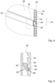
- figure 5 shows the carriage element 54 and the rail element 20 of the holding unit 16 in a sectional view along the sectional plane V in figure 4 .
- the carriage element 54 has a latching lug 64 which, in a latched state, latches into the latching positions 24, 26 of the latching means 22. Holding forces occurring when holding the storage units 14 , 36 , 38 can thus be introduced into the rail element 20 via the carriage element 54 .
- the carriage element 54 can preferably have an insertion aid 65 in one embodiment.
- the insertion aid 65 can be provided on the latching lug 64 .
- the insertion aid 65 advantageously facilitates locking into a locking position 24, 26 or unlocking/removing from a locking position 24, 26.
- FIG 6 shows the holding unit 16 during a height adjustment of a holding element 18 of the holding unit 16 in a perspective view.
- the holding element 18 is tiltably mounted on the rail element 20 .
- the holding element 18 can be tilted in such a way that an upper side 66 of the holding element 18 is closer together in a tilted state the panel element 28 is located as an underside 68 of the holding element 18.
- the holding element 18 can be adjusted in height.
- the carriage element 54 is moved up or down in a vertical direction along the main extension direction of the rail element 20 .
- the holding element 18 is movably mounted in a guided manner along the rail element 20 by means of the fastening element 56 and the carriage element 54 .
- a tilting of the holding element 18 and a subsequent height adjustment of the holding element 18 are possible without tools.
- figure 7 shows the carriage element 54 and the rail element 20 of the holding unit 16 during a height adjustment of the holding element 18 in a sectional view along the sectional plane V in figure 4 .
- the carriage element 54 is tilted.
- the carriage element 54 can then be moved along the rail element 20 and can be locked again at any other locking position 26 .
- the carriage element 54 can preferably have a contact surface 55 in one embodiment.
- the contact surface 55 preferably faces the screen element 28 .
- the contact surface 55 is arranged on a side of the carriage element 54 opposite the locking lug 64 .
- the contact surface 55 can be brought into contact with the screen element 28 when the height is adjusted.
- the panel element serves as a stop in this case, so that when tilting, a user receives an indication that maximum tilting has now been reached and trouble-free height adjustment is possible.
- Latching takes place by the holding element 18 tilting back, as a result of which the carriage element 54 tilts back.
- the latching lug 56 latches in a latching position 24 , 26 .
- the holding element 18 tilts back, in particular automatically, as a result of the force of gravity on the holding element 18 , in particular as soon as the operator lets go of the holding element 18 .
- FIG 8 shows an exploded view of the holding unit 16, the screen element 28 and a storage unit 38 of the household appliance device.
- the holding unit 16 has the two rail elements 20 , 58 .
- the rail elements 20, 58 each have a cover profile 70, 72 which at least partially covers the latching means 22, 74 of the rail elements 20, 58.
- the carriage elements 54, 60 of the holding unit 16 are each formed in one piece with a fastening element 56, 62 of the holding unit 16.
- the fastening elements 56, 62 can be pushed laterally into the holding element 18.
- the hook profile 52 of the storage unit 38 is positively connected to the holding element 18 in a mounted state. Furthermore, the hook profile 52 of the storage unit 38 is positively connected to the panel element 28 in an assembled state.
- the locking position 24, 26 of the holding element 18 is locked by the storage unit 38 in an assembled state.
- a storage unit 14 , 36 , 38 suspended from the holding element 18 may first have to be removed from the holding element 18 .
Landscapes
- Engineering & Computer Science (AREA)
- Chemical & Material Sciences (AREA)
- Combustion & Propulsion (AREA)
- Physics & Mathematics (AREA)
- Mechanical Engineering (AREA)
- Thermal Sciences (AREA)
- General Engineering & Computer Science (AREA)
- Drawers Of Furniture (AREA)
- Supports Or Holders For Household Use (AREA)
Description
Die Erfindung betrifft Haushaltskältegerät nach Anspruch 1 und ein Verfahren zur Montage eines Haushaltskältegeräts nach Anspruch 12.The invention relates to a household refrigeration appliance according to claim 1 and a method for assembling a household refrigeration appliance according to
Aus dem Stand der Technik sind bereits Kühlschränke mit Halteprofilen bekannt, in welche Abstellplatten an einer Rastposition des Halteprofils eingehängt werden können. Zu einer Höhenverstellung der Abstellplatten können die Abstellplatten ausgehängt und an einer anderen Rastposition des Halteprofils wieder eingehängt werden.Refrigerators with holding profiles are already known from the prior art, in which shelves can be hung at a locking position of the holding profile. To adjust the height of the storage shelves, the storage shelves can be unhooked and hung again at a different latching position of the holding profile.
Aus der
Darüber hinaus ist aus der
Darüber hinaus ist aus der
Die Aufgabe der Erfindung besteht insbesondere darin, eine gattungsgemäße Vorrichtung mit verbesserten Eigenschaften hinsichtlich einer Halterung von Ablageeinheiten bereitzustellen. Die Aufgabe wird erfindungsgemäß durch die Merkmale der Patentansprüche 1 und 12 gelöst, während vorteilhafte Ausgestaltungen und Weiterbildungen der Erfindung den Unteransprüchen entnommen werden können.The object of the invention is, in particular, to provide a device of the generic type with improved properties with regard to holding storage units. The object is achieved according to the invention by the features of
Die Erfindung geht aus von einem Haushaltskältegerät mit zumindest einer Ablageeinheit und mit zumindest einer Halteeinheit, die zumindest ein vertikales Schienenelement und zumindest ein mit dem Schienenelement verbundenes Halteelement aufweist, das zu einem Halten der Ablageeinheit vorgesehen ist.The invention is based on a household refrigeration appliance with at least one storage unit and with at least one holding unit, which has at least one vertical rail element and at least one the rail element has connected holding element, which is provided for holding the storage unit.
Es wird erfindungsgemäß vorgeschlagen, dass das Halteelement an dem Schienenelement in eine zumindest im Wesentlichen vertikale Richtung höhenverstellbar gelagert ist.It is proposed according to the invention that the holding element is mounted on the rail element so that it can be adjusted in height in an at least essentially vertical direction.
Unter "vorgesehen" soll insbesondere speziell ausgelegt und/oder ausgestattet verstanden werden. Darunter, dass ein Objekt zu einer bestimmten Funktion vorgesehen ist, soll insbesondere verstanden werden, dass das Objekt diese bestimmte Funktion in zumindest einem Anwendungs- und/oder Betriebszustand erfüllt und/oder ausführt. Unter einer "Haushaltsgerätevorrichtung" soll in diesem Zusammenhang insbesondere zumindest ein Teil, insbesondere eine Unterbaugruppe, eines Haushaltsgeräts, insbesondere eines Haushaltskältegeräts, verstanden werden. Insbesondere kann die Haushaltsgerätevorrichtung auch das gesamte Haushaltsgerät, insbesondere das gesamte Haushaltskältege rät, umfassen. Besonders bevorzugt ist das Haushaltsgerät als Kühl- und/oder Gefriergerät, wie insbesondere als Kühlschrank, Kühltruhe, Gefrierschrank, Gefriertruhe, Kühlgefrierkombination und/oder Weinlagerschrank ausgebildet.“Provided” is to be understood in particular as being specially designed and/or equipped. The fact that an object is provided for a specific function is to be understood in particular to mean that the object fulfills and/or executes this specific function in at least one application and/or operating state. In this context, a “household appliance device” should be understood to mean in particular at least a part, in particular a subassembly, of a household appliance, in particular a household refrigeration appliance. In particular, the household appliance device can also be the entire household appliance, in particular the entire household refrigeration unit advises to include. The household appliance is particularly preferably designed as a refrigerator and/or freezer, in particular as a refrigerator, chest freezer, freezer, chest freezer, combined fridge-freezer and/or wine storage cabinet.
Unter einer "Ablageeinheit" soll insbesondere eine Einheit verstanden werden, die zu einem Abstellen oder Ablegen von Gegenständen, insbesondere von Lebensmitteln, vorgesehen ist. Insbesondere kann die Ablageeinheit zumindest im Wesentlichen plattenartig ausgebildet sein und/oder zumindest ein zumindest im Wesentlichen plattenartig ausgebildetes Element aufweisen. Unter einem "plattenartigen" Objekt soll dabei insbesondere ein Objekt verstanden werden, das entlang einer ersten Raumrichtung und entlang einer zweiten Raumrichtung eine erheblich größere Erstreckung aufweist als entlang einer dritten Raumrichtung, vorzugsweise eine um mindestens einen Faktor 5, vorteilhaft eine um mindestens einen Faktor 10 und besonders vorteilhaft eine um mindestens einen Faktor 20 größere Erstreckung, wobei die drei Raumrichtungen paarweise senkrecht aufeinander stehen sollen. Unter einer "Erstreckung entlang einer Richtung" eines Objekts soll in diesem Zusammenhang insbesondere ein maximaler Abstand zweier Punkte einer senkrechten Projektion des Objekts auf eine Ebene verstanden werden, die parallel zu der Richtung steht.A “storage unit” is to be understood in particular as a unit that is provided for putting down or depositing objects, in particular food. In particular, the storage unit can be designed at least essentially in the manner of a plate and/or have at least one element designed at least essentially in the manner of a plate. A "plate-like" object is to be understood in particular as an object that has a significantly greater extent along a first spatial direction and along a second spatial direction than along a third spatial direction, preferably by at least a factor of 5, advantageously by at least a factor of 10 and particularly advantageously an extension that is greater by at least a factor of 20, with the three spatial directions being intended to be perpendicular to one another in pairs. In this context, an “extension along a direction” of an object is to be understood in particular as a maximum distance between two points of a perpendicular projection of the object onto a plane that is parallel to the direction.
Erfindungsgemäß weist das Halteelement einen zumindest im Wesentlichen rechteckigen Querschnitt auf. Unter einem "zumindest im Wesentlichen rechteckigen Querschnitt" eines Objekts soll dabei insbesondere verstanden werden, dass für wenigstens 80 % aller Querschnitte des Objekts entlang zumindest einer Richtung ein Flächeninhalt einer Differenzfläche des Querschnitts und eines kleinsten den Querschnitt umgebenden Rechtecks maximal 20 %, vorteilhaft maximal 10 % und besonders vorteilhaft maximal 5 % des Flächeninhalts des Rechtecks beträgt. Erfindungsgemäß ist das Halteelement als eine rechteckige Halteleiste ausgebildet, vorteilhaft als eine mittels Extrusion herstellbare Halteleiste. Insbesondere kann das Halteelement zumindest im Wesentlichen aus einem Metall und/oder einem Kunststoff ausgebildet sein. Vorzugsweise ist das Halteelement als ein Hohlprofil ausgebildet. Unter "zumindest im Wesentlichen" soll in diesem Zusammenhang insbesondere zu wenigstens 75 %, vorzugsweise zu wenigstens 85 % und besonders bevorzugt zu wenigstens 95 % verstanden werden.According to the invention, the holding element has an at least substantially rectangular cross section. An "at least essentially rectangular cross-section" of an object should be understood in particular to mean that for at least 80% of all cross-sections of the object along at least one direction, a surface area of a differential area of the cross-section and a smallest rectangle surrounding the cross-section is a maximum of 20%, advantageously a maximum of 10 % and particularly advantageously a maximum of 5% of the area of the rectangle. According to the invention, the holding element is designed as a rectangular holding strip, advantageously as a holding strip that can be produced by means of extrusion. In particular, the holding element can be formed at least essentially from a metal and/or a plastic. The holding element is preferably designed as a hollow profile. In this context, “at least essentially” should be understood to mean in particular at least 75%, preferably at least 85% and particularly preferably at least 95%.
Durch die erfindungsgemäße Ausgestaltung kann insbesondere eine vorteilhafte Halterung von Ablageeinheiten bereitgestellt werden. Vorteilhaft kann eine einfache und zuverlässige Höhenverstellung von Ablageeinheiten erreicht werden. Insbesondere kann eine vertikale Position von Ablageeinheiten einer Größe eingestellter Gegenstände, insbesondere Lebensmittel, komfortabel angepasst werden. Insbesondere kann eine hohe Flexibilität erreicht werden. Vorteilhaft kann ein Innenraum einfach an Bedürfnisse eines Bedieners und/oder Benutzers angepasst werden. Ferner kann insbesondere eine komfortable Bedienung erreicht werden. Insbesondere kann vorteilhaft ein Haltesystem für verschieden ausgebildete Ablageeinheiten bereitgestellt werden. Weiterhin wird die Verwendung weitgehend ebener innerer Wände ermöglicht, wodurch diese insbesondere leicht zu reinigen sind. Insbesondere kann ein neuartiges, sehr hochwertiges Erscheinungsbild erreicht werden.The configuration according to the invention makes it possible in particular to provide an advantageous mounting for storage units. Advantageously, a simple and reliable Height adjustment of storage units can be achieved. In particular, a vertical position of storage units of the size of items that have been set, in particular groceries, can be comfortably adjusted. In particular, a high degree of flexibility can be achieved. Advantageously, an interior can easily be adapted to the needs of an operator and/or user. Furthermore, in particular, comfortable operation can be achieved. In particular, a holding system for differently designed storage units can advantageously be provided. Furthermore, the use of largely flat inner walls is made possible, as a result of which they are particularly easy to clean. In particular, a new, very high-quality appearance can be achieved.
Erfindungsgemäß wird vorgeschlagen, dass das Halteelement an dem Schienenelement in die Richtung geführt bewegbar gelagert ist. Darunter, dass ein Objekt an einem zweiten Objekt "geführt bewegbar gelagert" ist, soll hier insbesondere verstanden werden, dass das Objekt in zumindest einem Normalbetriebszustand relativ zu dem zweiten Objekt bewegt werden kann, insbesondere entlang einer durch das zweite Objekt vorgegebenen Trajektorie, insbesondere unter Einwirken von Kräften, die durchschnittliche Menschen ohne nennenswerte Anstrengung aufbringen können, beispielsweise mit einer Hand und/oder mit einem Arm und/oder mit einem oder mehreren Fingern. Erfindungsgemäß weist die Halteeinheit zumindest ein Schlittenelement auf, dass entlang einer Haupterstreckungsrichtung des Schienenelements geführt bewegbar gelagert ist und an welchem das Halteelement in zumindest einem montierten Zustand befestigt ist. Unter einer "Haupterstreckungsrichtung" eines Objekts soll dabei insbesondere eine Richtung verstanden werden, welche parallel zu einer längsten Kante eines kleinsten gedachten Quaders verläuft, welcher das Objekt gerade noch vollständig umschließt. Erfindungsgemäß weist die Halteeinheit zumindest ein Befestigungselement auf, welches das Halteelement in zumindest einem montierten Zustand mit dem Schlittenelement verbindet. Besonders vorteilhaft sind jedem Halteelement zwei Befestigungselemente zugeordnet, welche das Halteelement an zwei gegenüberliegenden Seiten halten, insbesondere in einem Abstand, der zumindest im Wesentlichen einer Länge des Halteelements entlang einer Haupterstreckungsrichtung des Halteelements entspricht. Vorteilhaft ist das Befestigungselement einstückig mit dem Halteelement verbunden. Unter "einstückig" soll insbesondere zumindest stoffschlüssig verbunden verstanden werden, beispielsweise durch einen Schweißprozess, einen Klebeprozess, einen Anspritzprozess und/oder einen anderen, dem Fachmann als sinnvoll erscheinenden Prozess, und/oder vorteilhaft in einem Stück geformt verstanden werden, wie beispielsweise durch eine Herstellung aus einem Guss und/oder durch eine Herstellung in einem Ein- oder Mehrkomponentenspritzverfahren und vorteilhaft aus einem einzelnen Rohling. Insbesondere wird das Halteelement von dem Schlittenelement geführt, insbesondere während eines Verschiebens des Halteelements in eine vertikale Richtung. Insbesondere ist das Schlittenelement mit dem Befestigungselement, insbesondere einstückig, verbunden.According to the invention, it is proposed that the holding element is mounted on the rail element such that it can be moved in the guided direction. The fact that an object is "mounted in a guided and movable manner" on a second object is to be understood here in particular as meaning that the object can be moved in at least one normal operating state relative to the second object, in particular along a trajectory specified by the second object, in particular under Application of forces that average people can apply without significant effort, for example with a hand and/or with an arm and/or with one or more fingers. According to the invention, the holding unit has at least one carriage element that is mounted so as to be guided and movable along a main extension direction of the rail element and to which the holding element is fastened in at least one assembled state. A "main extension direction" of an object is to be understood in particular as a direction which runs parallel to a longest edge of the smallest imaginary cuboid which just about completely encloses the object. According to the invention, the holding unit has at least one fastening element which connects the holding element to the carriage element in at least one assembled state. Each holding element is particularly advantageously assigned two fastening elements which hold the holding element on two opposite sides, in particular at a distance which at least essentially corresponds to a length of the holding element along a main extension direction of the holding element. The fastening element is advantageously connected in one piece to the holding element. "In one piece" is to be understood in particular as being at least cohesively connected, for example by a welding process, a gluing process, an injection molding process and/or another process that appears sensible to the person skilled in the art, and/or advantageously formed in one piece, such as by production from a single cast and/or by production in one Single or multi-component injection molding process and advantageously from a single blank. In particular, the holding element is guided by the carriage element, in particular during a displacement of the holding element in a vertical direction. In particular, the carriage element is connected to the fastening element, in particular in one piece.
Vorteilhaft umfasst die Haushaltsgerätevorrichtung zumindest einen Gerätekorpus mit zumindest einer Rückwand, in deren Nahbereich die Halteeinheit angeordnet ist. Insbesondere begrenzt und/oder definiert der Gerätekorpus der Haushaltsgerätevorrichtung insbesondere einen Innenraum, vorzugsweise zumindest einen Nutzraum, und weist insbesondere eine Zugangsöffnung auf. Insbesondere ist eine an einer Vorderseite des Gerätekorpus angeordnete Tür der Haushaltsgerätevorrichtung vom Gerätekorpus verschieden ausgebildet. Unter einem "Nahbereich" soll in diesem Zusammenhang insbesondere ein Raumbereich verstanden werden, dessen Punkte sich höchstens 20 cm, vorteilhaft höchstens 15 cm, besonders vorteilhaft höchstens 10 cm und bevorzugt höchstens 7 cm von der Rückwand entfernt befinden. Vorteilhaft ist die Halteeinheit mit der Rückwand verbunden. Besonders vorteilhaft ist das Schienenelement der Halteeinheit mit der Rückwand verbunden. Hierdurch kann insbesondere eine vorteilhafte Innenraumausnutzung erreicht werden. Ferner können hierdurch vorteilhafte Eigenschaften hinsichtlich einer Reinigung von hinten gehaltenen Ablageeinheiten erzielt werden.The domestic appliance device advantageously comprises at least one appliance body with at least one rear wall, in the vicinity of which the holding unit is arranged. In particular, the appliance body of the household appliance device delimits and/or defines in particular an interior space, preferably at least one usable space, and in particular has an access opening. In particular, a door of the domestic appliance device that is arranged on a front side of the appliance body is designed differently from the appliance body. In this context, a “near area” is to be understood in particular as a spatial area whose points are at most 20 cm, advantageously at most 15 cm, particularly advantageously at most 10 cm and preferably at most 7 cm away from the rear wall. The holding unit is advantageously connected to the rear wall. The rail element of the holding unit is particularly advantageously connected to the rear wall. In this way, in particular, an advantageous utilization of the interior space can be achieved. Furthermore, advantageous properties with regard to cleaning storage units held from behind can be achieved in this way.
Ferner wird vorgeschlagen, dass die Haushaltsgerätevorrichtung zumindest ein Blendenelement aufweist, das zumindest teilweise auf einer von der Rückwand abgewandten Seite der Halteeinheit angeordnet ist. Insbesondere befinden sich wenigstens 70 %, vorteilhaft wenigstens 80 %, besonders vorteilhaft wenigstens 90 % und besonders bevorzugt wenigstens 95 % aller Punkte des Blendenelements auf einer jeweiligen Geraden senkrecht zu der Rückwand durch den entsprechenden Punkt weiter von der Rückwand entfernt als der am weitesten von der Rückwand entfernte Punkt der Halteeinheit auf der jeweiligen Geraden. Insbesondere ist das Blendenelement mit der Halteeinheit verbunden. Vorteilhaft ist das Blendenelement einstückig mit der Halteeinheit verbunden. Insbesondere bildet das Blendenelement in einem montierten Zustand ein vor der Rückwand des Gerätekorpus angeordnetes rückwärtiges Wandelement aus. Vorteilhaft weist das Blendenelement eine Höhe und eine Breite auf, die zumindest im Wesentlichen einer Höhe und einer Breite der Rückwand des Gerätekorpus entsprechen. Unter "zumindest im Wesentlichen" soll in diesem Zusammenhang insbesondere eine Abweichung der Höhe/Breite des Blendenelements von der Höhe/Breite der Rückwand von maximal 20 %, vorteilhaft von maximal 10 % und besonders vorteilhaft von maximal 5 % verstanden werden. Hierdurch kann vorteilhaft ein leicht zu reinigender Innenraum bereitgestellt werden. Ferner kann hierdurch vorteilhaft eine Beschädigung und/oder eine Verschmutzung der Halteeinheit vermieden werden. Weiterhin kann hierdurch vorteilhaft ein rückwärtiges Wandelement mit speziellen Material- und/oder Beleuchtungsmöglichkeiten bereitgestellt werden, das unabhängig von einer Rückwand eines Haushaltsgerätekorpus herstellbar ist.It is also proposed that the domestic appliance device has at least one panel element which is at least partially arranged on a side of the holding unit which is remote from the rear wall. In particular, at least 70%, advantageously at least 80%, particularly advantageously at least 90% and particularly preferably at least 95% of all points of the panel element are located on a respective straight line perpendicular to the rear wall through the corresponding point further away from the rear wall than the point furthest from the Rear wall distant point of the holding unit on the respective straight line. In particular, the panel element is connected to the holding unit. The screen element is advantageously connected in one piece to the holding unit. In particular, the screen element forms a front of the rear wall in a mounted state of the device body arranged rear wall element. The panel element advantageously has a height and a width which at least essentially correspond to a height and a width of the rear wall of the device body. In this context, “at least essentially” should be understood to mean a deviation of the height/width of the panel element from the height/width of the rear wall of at most 20%, advantageously at most 10% and particularly advantageously at most 5%. As a result, an interior space that is easy to clean can advantageously be provided. Furthermore, damage to and/or contamination of the holding unit can advantageously be avoided as a result. Furthermore, this can advantageously provide a rear wall element with special material and/or lighting options, which can be produced independently of a rear wall of a household appliance body.
Vorteilhaft wird vorgeschlagen, dass das Halteelement zumindest teilweise auf einer von der Rückwand abgewandten Seite des Blendenelements angeordnet ist. Insbesondere befinden sich wenigstens 70 %, vorteilhaft wenigstens 80 %, besonders vorteilhaft wenigstens 90 % und besonders bevorzugt wenigstens 95 % aller Punkte des Halteelements auf einer jeweiligen Geraden senkrecht zu der Rückwand durch den entsprechenden Punkt weiter von der Rückwand entfernt als der am weitesten von der Rückwand entfernte Punkt des Blendenelements auf der jeweiligen Geraden. Vorteilhaft sind jedem Halteelement zwei Befestigungselemente der Halteeinheit zugeordnet. Besonders vorteilhaft ragen die beiden Befestigungselemente der Halteeinheit an jeweils einer Seite des Blendenelements an dem Blendenelement vorbei in Richtung der von der Rückwand abgewandten Seite des Blendenelements und halten das Halteelement auf der von der Rückwand abgewandten Seite des Blendenelements. Vorzugsweise ist das Blendenelement mit dem Schienenelement verbunden. Besonders bevorzugt deckt das Blendenelement die Halteeinheit zu einer von der Rückwand abgewandten Seite der Halteeinheit hin zumindest teilweise ab. Insbesondere deckt das Blendenelement sämtliche Teile der Halteeinheit bis auf die Halteelemente und die Befestigungselemente zu der von der Rückwand abgewandten Seite der Halteeinheit hin ab. Hierdurch kann vorteilhaft eine Verschmutzung der Halteeinheit vermieden werden. Weiterhin vorteilhaft wird hierdurch eine Verwendung eines kostengünstig und einfach herzustellenden Blendenelements ermöglicht.It is advantageously proposed that the retaining element is arranged at least partially on a side of the screen element that faces away from the rear wall. In particular, at least 70%, advantageously at least 80%, particularly advantageously at least 90% and particularly preferably at least 95% of all points of the holding element are located on a respective straight line perpendicular to the rear wall through the corresponding point further away from the rear wall than the point furthest from the Rear panel distant point of the screen element on the respective straight line. Two fastening elements of the holding unit are advantageously assigned to each holding element. Particularly advantageously, the two fastening elements of the holding unit protrude on one side of the panel element past the panel element in the direction of the side of the panel element facing away from the rear wall and hold the holding element on the side of the panel element facing away from the rear wall. The panel element is preferably connected to the rail element. Particularly preferably, the screen element at least partially covers the holding unit on a side of the holding unit facing away from the rear wall. In particular, the panel element covers all parts of the holding unit apart from the holding elements and the fastening elements on the side of the holding unit facing away from the rear wall. As a result, soiling of the holding unit can advantageously be avoided. This also advantageously allows the use of a screen element that is inexpensive and easy to produce.
In einer vorteilhaften Ausgestaltung der Erfindung wird vorgeschlagen, dass eine Haupterstreckungsrichtung des Halteelements in zumindest einem montierten Zustand in eine zumindest im Wesentlichen horizontale Richtung verläuft. Unter "zumindest im Wesentlichen in horizontaler Richtung" soll dabei insbesondere eine Ausrichtung relativ zu einer Flächennormalen eines Untergrunds, insbesondere einer Erdoberfläche verstanden werden, insbesondere in zumindest einem Normalbetriebszustand der Haushaltsgerätevorrichtung, wobei die Richtung gegenüber einer Richtung senkrecht zu der Flächennormalen des Untergrunds eine Abweichung insbesondere kleiner als 8°, vorteilhaft kleiner als 5° und besonders vorteilhaft kleiner als 2° aufweist. Vorteilhaft verläuft die Haupterstreckungsrichtung des Halteelements zumindest im Wesentlichen parallel zu der Rückwand des Gerätekorpus. Unter "zumindest im Wesentlichen parallel" soll hier insbesondere eine Ausrichtung einer Richtung relativ zu einer Bezugsrichtung, insbesondere in einer Ebene, verstanden werden, wobei die Richtung gegenüber der Bezugsrichtung eine Abweichung insbesondere kleiner als 8°, vorteilhaft kleiner als 5° und besonders vorteilhaft kleiner als 2° aufweist. Hierdurch kann insbesondere eine vorteilhafte Statik erreicht werden. Ferner können hierdurch leicht zu reinigende Halteelemente bereitgestellt werden.In an advantageous embodiment of the invention, it is proposed that a main extension direction of the holding element runs in at least one mounted state in an at least substantially horizontal direction. "At least essentially in the horizontal direction" is to be understood in particular as an alignment relative to a surface normal of a subsurface, in particular a surface of the earth, in particular in at least one normal operating state of the household appliance device, with the direction being different from a direction perpendicular to the surface normal of the subsurface, in particular less than 8°, advantageously less than 5° and particularly advantageously less than 2°. The main extension direction of the holding element advantageously runs at least essentially parallel to the rear wall of the device body. "At least essentially parallel" is to be understood here in particular as an alignment of a direction relative to a reference direction, in particular in a plane, with the direction relative to the reference direction deviating in particular by less than 8°, advantageously less than 5° and particularly advantageously less than 2°. In this way, advantageous statics can be achieved in particular. Furthermore, holding elements that are easy to clean can be provided in this way.
Ferner wird vorgeschlagen, dass die Ablageeinheit in dem montierten Zustand in eine Richtung parallel zu der Haupterstreckungsrichtung des Halteelements verschiebbar an der Halteeinheit, insbesondere an dem Halteelement, gelagert ist. Insbesondere bleibt während eines Verschiebens eine Position des Objekts relativ zu dem zweiten Objekt bei einer Betrachtung parallel zu der Richtung zumindest im Wesentlichen unverändert, wohingegen sich eine Position des Objekts relativ zu dem zweiten Objekt bei einer Betrachtung senkrecht zu der Richtung ändert. Unter "zumindest im Wesentlichen unverändert" soll in diesem Zusammenhang insbesondere verstanden werden, dass sich die Position des Objekts relativ zu dem zweiten Objekt um weniger als 10 mm, vorteilhaft um weniger als 5 mm und besonders vorteilhaft um weniger als 1 mm verändert. Insbesondere ist die Ablageeinheit in einem beladenen Zustand und in einem unbeladenen Zustand verschiebbar gelagert. Hierdurch kann eine hohe Flexibilität hinsichtlich einer Anordnung von Ablageeinheit erreicht werden. Insbesondere kann eine Haushaltsgerätevorrichtung an eine Anordnung und/oder an eine Größe eingestellter und/oder eingelegter Gegenstände, wie beispielsweise Lebensmittel, angepasst werden. Weiterhin vorteilhaft kann eine komfortable Bedienung erreicht werden.Furthermore, it is proposed that the storage unit, in the assembled state, be mounted on the holding unit, in particular on the holding element, such that it can be displaced in a direction parallel to the main extension direction of the holding element. In particular, during a shifting, a position of the object relative to the second object remains at least substantially unchanged when viewed parallel to the direction, whereas a position of the object relative to the second object changes when viewed perpendicular to the direction. In this context, “at least essentially unchanged” is to be understood in particular as meaning that the position of the object relative to the second object changes by less than 10 mm, advantageously by less than 5 mm and particularly advantageously by less than 1 mm. In particular, the storage unit is movably mounted in a loaded state and in an unloaded state. As a result, a high degree of flexibility with regard to an arrangement of the storage unit can be achieved. In particular, a domestic appliance device can be adapted to an arrangement and/or to a size of adjusted and/or inserted objects, such as food. Comfortable operation can also advantageously be achieved.
Vorteilhaft weist das Schienenelement zumindest ein Rastmittel auf, das zumindest zwei verschiedene Rastpositionen für das Halteelement bereitstellt. Insbesondere ist das Rastmittel als zumindest ein Teil einer Zahnstange ausgebildet. Vorzugsweise weist das Schienenelement zumindest ein Schienenprofil auf, insbesondere ein zu einer seiner Längsseiten hin offenes Schienenprofil. Besonders bevorzugt bilden mehrere Rastmittel das Schienenprofil aus. Es ist aber auch denkbar, dass das Rastmittel innerhalb des Schienenprofils angeordnet. Vorteilhaft weist das Schienenelement ein Abdeckprofil auf, welches die offene Längsseite des Schienenprofils zu wenigstens einem Großteil abdeckt. Besonders vorteilhaft deckt das Abdeckprofil das Rastmittel und die offene Längsseite des Schienenprofils zu wenigstens einem Großteil ab. Unter dem Ausdruck "zu wenigstens einem Großteil" sollen dabei insbesondere zumindest zu 55 %, vorteilhaft zumindest zu 65 %, vorzugsweise zumindest zu 75 %, besonders bevorzugt zumindest zu 85 % und besonders vorteilhaft zumindest zu 95 % verstanden werden. Hierdurch kann vorteilhaft eine vertikale Position einer Ablageeinheit fixiert werden. Ferner kann hierdurch vorteilhaft eine Ablageeinheit sicher gehalten werden.The rail element advantageously has at least one latching means which provides at least two different latching positions for the holding element. In particular, the latching means is designed as at least part of a toothed rack. The rail element preferably has at least one rail profile, in particular a rail profile which is open towards one of its longitudinal sides. Particularly preferably, a plurality of latching means form the rail profile. But it is also conceivable that the latching means is arranged inside the rail profile. The rail element advantageously has a cover profile which covers at least a large part of the open longitudinal side of the rail profile. In a particularly advantageous manner, the covering profile covers at least a large part of the latching means and the open longitudinal side of the rail profile. The expression "at least a large part" is to be understood in particular as at least 55%, advantageously at least 65%, preferably at least 75%, particularly preferably at least 85% and particularly advantageously at least 95%. As a result, a vertical position of a storage unit can advantageously be fixed. Furthermore, a storage unit can advantageously be held securely in this way.
Besonders vorteilhaft ist eine Rastposition des Halteelements werkzeuglos veränderbar. Vorteilhaft ist eine Rastposition des Halteelements in einer einhändigen Betätigung möglich, insbesondere für einen durchschnittlichen Menschen, insbesondere ohne nennenswerte Anstrengung. Hierdurch kann eine komfortable Bedienung ermöglicht werden.A locking position of the holding element can be changed without tools in a particularly advantageous manner. Advantageously, a locking position of the holding element is possible in a one-hand operation, in particular for an average person, in particular without any significant effort. This enables convenient operation.
Weiterhin wird vorgeschlagen, dass das Halteelement zu einer Veränderung der Rastposition gegenüber dem Schienenelement verkippbar gelagert ist. Insbesondere ist das Halteelement derart gelagert, dass zu einer Veränderung der Rastposition eine obere Kante des Halteelements in eine Richtung auf die Rückwand zu und/oder eine untere Kante in eine Richtung von der Rückwand weg verkippt wird. Insbesondere weist das Schlittenelement zumindest eine Rastnase auf, die bei einem Verkippen des Halteelements aus einer Rastposition der Rastschiene heraus bewegt wird. Vorteilhaft ist das Schlittenelement in einem verkippten Zustand des Halteelements entlang einer Haupterstreckungsrichtung des Schienenelements verschiebbar. Insbesondere ist in einem unverkippten Zustand des Halteelements eine Bewegung des Schlittenelements entlang einer Haupterstreckungsrichtung des Schienenelements, insbesondere durch ein Einrasten der Rastnase in einer Rastposition, verriegelt. Vorzugsweise weist die Halteeinheit zumindest ein Federelement auf, das dazu vorgesehen ist, das Halteelement selbstständig in einen unverkippten Zustand zu kippen. Vorzugsweise ist ein minimaler Abstand zwischen dem Halteelement und dem Blendenelement kleiner als ein Durchmesser eines durchschnittlichen menschlichen Fingers, insbesondere deutlich kleiner, insbesondere in einem unverkippten Zustand des Halteelements. Es ist aber auch denkbar, dass ein minimaler Abstand zwischen dem Halteelement und dem Blendenelement größer, insbesondere deutlich größer, ist als ein Durchmesser eines durchschnittlichen menschlichen Fingers, insbesondere in einem verkippten Zustand des Halteelements. Hierdurch kann insbesondere eine komfortabel zu bedienende Höhenverstellung bereitgestellt werden. Vorteilhaft kann hierdurch ein sicherer Mechanismus für eine Höhenverstellung bereitgestellt werden. Ferner kann hierdurch vorteilhaft ein Einklemmen von Fingern vermieden werden.Furthermore, it is proposed that the holding element be mounted such that it can be tilted in relation to the rail element in order to change the locking position. In particular, the holding element is mounted in such a way that, to change the locking position, an upper edge of the holding element is tilted in a direction towards the rear wall and/or a lower edge is tilted in a direction away from the rear wall. In particular, the carriage element has at least one latching lug, which is moved out of a latching position of the latching rail when the holding element is tilted. The carriage element can advantageously be displaced along a main extension direction of the rail element when the holding element is in a tilted state. In particular, in a non-tilted state of the holding element, a movement of the carriage element along a main extension direction of the rail element is locked, in particular by the latching lug latching in a latching position. Preferably, the holding unit has at least one spring element, which is provided for the purpose of automatically turning the holding element into a to tilt in the non-tilted state. A minimum distance between the holding element and the panel element is preferably smaller than the diameter of an average human finger, in particular significantly smaller, in particular when the holding element is in a non-tilted state. However, it is also conceivable that a minimum distance between the holding element and the screen element is larger, in particular significantly larger, than the diameter of an average human finger, in particular when the holding element is in a tilted state. In this way, in particular, a height adjustment that is easy to operate can be provided. A secure mechanism for a height adjustment can advantageously be provided in this way. Furthermore, in this way, trapping of fingers can advantageously be avoided.
In einer bevorzugten Ausgestaltung der Erfindung wird vorgeschlagen, dass die Ablageeinheit dazu vorgesehen ist, in zumindest einem montierten Zustand zumindest eine Rastposition des Halteelements zu verriegeln. Insbesondere weist die Ablageeinheit zumindest einen Fortsatz auf, der eine Kippbewegung des Halteelements relativ zu der Rückwand verriegelt. Vorteilhaft ist der Fortsatz als ein Hakenprofil ausgebildet, der in einem montierten Zustand formschlüssig mit dem Halteelement verbunden ist. Besonders vorteilhaft ist in einem montierten Zustand der Fortsatz formschlüssig mit einem Blendenelement der Halteeinheit verbunden. Vorteilhaft wird hierdurch eine versehentliche Höhenverstellung vermieden. Insbesondere wird hierdurch vorteilhaft eine Position einer Ablageeinheit gesichert. Ferner sichern sich hierdurch Ablageeinheiten selbst gegen ein Herausfallen. Hierdurch kann vorteilhaft ein sehr stabiles System mit wenig Toleranz bereitgestellt werden.In a preferred embodiment of the invention, it is proposed that the storage unit is provided to lock at least one latching position of the holding element in at least one assembled state. In particular, the storage unit has at least one extension that locks a tilting movement of the holding element relative to the rear wall. The extension is advantageously designed as a hook profile which is positively connected to the holding element in a mounted state. In an assembled state, the extension is particularly advantageously connected in a form-fitting manner to a screen element of the holding unit. This advantageously avoids accidental height adjustment. In particular, this advantageously secures a position of a storage unit. Furthermore, as a result, storage units secure themselves against falling out. As a result, a very stable system with little tolerance can advantageously be provided.
In einer bevorzugten Ausgestaltung der Erfindung wird vorgeschlagen, dass die Ablageeinheit zu einer werkzeuglosen Montage und/oder Demontage an/von der Halteeinheit vorgesehen ist. Insbesondere ist die Ablageeinheit durch eine lineare Bewegung und/oder eine Kippbewegung der Ablageeinheit relativ zur Halteeinheit montierbar und/oder demontierbar ausgebildet. Hierdurch kann vorteilhaft eine einfache Höhenverstellung der Ablageeinheit erzielt werden. Weiterhin vorteilhaft kann hierdurch eine Anordnung von Ablageeinheiten komfortabel angepasst werden.In a preferred embodiment of the invention, it is proposed that the storage unit be provided for tool-free assembly and/or disassembly on/from the holding unit. In particular, the storage unit can be assembled and/or disassembled by a linear movement and/or a tilting movement of the storage unit relative to the holding unit. In this way, a simple height adjustment of the storage unit can advantageously be achieved. In this way, an arrangement of storage units can also advantageously be conveniently adapted.
Vorteilhaft weist die Ablageeinheit zumindest eine Abstellplatte auf. Unter einer "Abstellplatte" soll dabei insbesondere ein plattenartiges Element verstanden werden, welches zu einem Abstellen oder Ablegen von Gegenständen, insbesondere von Lebensmitteln, vorgesehen ist. Hierdurch kann vorteilhaft ein sicheres Abstellen von Gegenständen, insbesondere Lebensmitteln, auf der Ablageeinheit erreicht werden. Insbesondere ist hierdurch vorteilhaft die Ablageeinheit leicht zu reinigen.The storage unit advantageously has at least one storage shelf. A "storage plate" is to be understood in particular as a plate-like element which is provided for placing or setting down objects, in particular food is. In this way, objects, in particular foodstuffs, can advantageously be set down safely on the storage unit. In particular, this advantageously makes it easy to clean the storage unit.
Vorzugsweise ist die Abstellplatte zumindest teilweise transparent und rahmenlos und/oder zumindest teilweise transluzent und rahmenlos ausgebildet. Unter zumindest teilweise "transparent" soll dabei insbesondere zumindest teilweise transparent für sichtbares Licht verstanden werden, insbesondere eine Transparenz von zumindest 5 %, bevorzugt von zumindest 10 %, besonders bevorzugt von zumindest 20 %, vorteilhaft von zumindest 50 % und besonders vorteilhaft von zumindest 80 %, wobei ein transmittiertes Licht zumindest im Wesentlichen parallel zu einem einfallenden Licht ist. Unter zumindest teilweise "transluzent" soll dabei insbesondere zumindest teilweise transluzent für sichtbares Licht verstanden werden, insbesondere eine Durchlässigkeit von zumindest 5 %, bevorzugt von zumindest 10 %, besonders bevorzugt von zumindest 20 %, vorteilhaft von zumindest 50 % und besonders vorteilhaft von zumindest 80 % für einfallendes Licht, wobei austretendes Licht zumindest im Wesentlichen unter einem von 0 verschiedenen Winkel relativ zu dem einfallenden Licht gestreut wird. Unter "rahmenlos" soll dabei insbesondere verstanden werden, dass die gesamte Abstellplatte aus einem Material gefertigt ist. Insbesondere weist die Abstellplatte dabei zu ihren Rändern hin denselben Querschnitt auf wie an ihren Rändern. Insbesondere ist die Abstellplatte zumindest teilweise aus Glas, vorteilhaft zumindest teilweise aus Sicherheitsglas ausgebildet. Insbesondere kann die Abstellplatte zumindest teilweise aus zumindest teilweise trübem Glas, insbesondere Milchglas ausgebildet sein. Vorteilhaft ist die Abstellplatte als rahmenlose Glasplatte ausgebildet. Es ist aber auch denkbar, dass die Abstellplatte aus einem Kunststoff gefertigt ist. Hierdurch können vorteilhaft unter der Abstellplatte befindliche Gegenstände durch die Abstellplatte hindurch sichtbar sein. Insbesondere kann dadurch ein Bedienkomfort erhöht werden.The shelf is preferably at least partially transparent and frameless and/or at least partially translucent and frameless. At least partially "transparent" is to be understood in particular as at least partially transparent to visible light, in particular a transparency of at least 5%, preferably at least 10%, particularly preferably at least 20%, advantageously at least 50% and particularly advantageously at least 80% %, wherein a transmitted light is at least substantially parallel to an incident light. At least partially "translucent" is to be understood in particular as at least partially translucent for visible light, in particular a permeability of at least 5%, preferably at least 10%, particularly preferably at least 20%, advantageously at least 50% and particularly advantageously at least 80% % for incident light, wherein exiting light is at least substantially scattered at an angle other than 0 relative to the incident light. “Frameless” is to be understood in particular as meaning that the entire shelf is made from one material. In particular, the shelf has the same cross-section towards its edges as at its edges. In particular, the shelf is at least partially made of glass, advantageously at least partially made of safety glass. In particular, the shelf can be formed at least partially from at least partially opaque glass, in particular frosted glass. The shelf is advantageously designed as a frameless glass plate. But it is also conceivable that the shelf is made of a plastic. As a result, objects located under the storage shelf can advantageously be visible through the storage shelf. In particular, ease of use can be increased as a result.
Ferner geht die Erfindung aus von einem Verfahren zur Montage eines Haushaltskältegeräts nach einem der vorhergehend beschriebenen Ausführungsformen, umfassend die Schritte: Bereitstellen eines zumindest eines vertikalen Schienenelements, zumindest eines Halteelement, zumindest eines Schlittenelements und zumindest eines Befestigungselements, wobei das Schlittenelement und das Befestigungselement miteinander verbindbar sind; Anordnen des Halteelements an dem Befestigungselement, wobei das Befestigungselement seitlich in das Halteelement eingeschoben wird, und wobei das Halteelement eine rechteckige Halteleiste ausbildet; und Anordnen des Schlittenelements an dem vertikalen Schienenelement durch die Bewegung in horizontaler Richtung.Furthermore, the invention is based on a method for assembling a domestic refrigeration appliance according to one of the previously described embodiments, comprising the steps: providing at least one vertical rail element, at least one holding element, at least one carriage element and at least one fastening element, the carriage element and the fastening element being connectable to one another are; Arranging the holding element on the fastening element, the fastening element being pushed laterally into the holding element, and the holding element forming a rectangular holding strip; and placing the carriage member on the vertical rail member by the movement in the horizontal direction.
Vorzugsweise wird das Anordnen des Halteelements an dem Befestigungselement durch eine Bewegung in horizontaler Richtung durch ein Verbinden mittels Ineinanderschieben und/oder Ineinandergreifen erreicht.Preferably, the positioning of the retaining element on the fastening element is achieved by movement in the horizontal direction by means of telescoping and/or interlocking.
Vorzugsweise wird das Anordnen des Schlittenelements an dem vertikalen Schienenelement durch die Bewegung in horizontaler Richtung durch Einschieben, vorzugsweise seitliches Einschieben, einer Rastnase des Schlittenelements in eine Rastposition des vertikalen Schienenelements erreicht.The arrangement of the carriage element on the vertical rail element is preferably achieved by the movement in the horizontal direction by pushing in, preferably laterally, a locking lug of the carriage element into a locking position of the vertical rail element.
Vorzugsweise umfasst das Verfahren den weiteren Schritt: Anordnen einer Ablageeinheit an dem Halteelement.The method preferably includes the further step: arranging a storage unit on the holding element.
Vorzugsweise wird das Anordnen durch ein Einhängen eines Hakenprofils der Ablageeinheit an dem Halteelement erreicht.The arrangement is preferably achieved by hanging a hook profile of the storage unit on the holding element.
Es wird erfindungsgemäß vorgeschlagen, dass das Halteelement entlang einer zumindest im Wesentlichen vertikalen Richtung höhenverstellbar an dem Schienenelement gelagert montiert wird. Hierdurch kann eine vorteilhafte Halterung von Ablageeinheiten bereitgestellt werden. Vorteilhaft kann eine einfache und zuverlässige Höhenverstellung von Ablageeinheiten erreicht werden. Insbesondere kann eine vertikale Position von Ablageeinheiten eingestellten Gegenständen, insbesondere Lebensmitteln, komfortabel angepasst werden. Insbesondere kann eine hohe Flexibilität erreicht werden. Vorteilhaft kann ein Innenraum einfach an Bedürfnisse eines Bedieners angepasst werden. Ferner kann insbesondere eine komfortable Bedienung erreicht werden. Insbesondere kann vorteilhaft ein Haltesystem für verschieden ausgebildete Ablageeinheiten bereitgestellt werden. Weiterhin können vorteilhaft Ablageeinheiten in einem Gerätekorpus mit überwiegend ebenen inneren Wänden angeordnet werden, wodurch insbesondere die Wände leicht zu reinigen sind. Insbesondere kann ein neuartiges, sehr hochwertiges Erscheinungsbild erreicht werden. Die Haushaltsgerätevorrichtung soll hierbei nicht auf die oben beschriebene Anwendung und Ausführungsform beschränkt sein. Insbesondere kann die Haushaltsgerätevorrichtung zu einer Erfüllung einer hierin beschriebenen Funktionsweise eine von einer hierin genannten Anzahl von einzelnen Elementen, Bauteilen und Einheiten abweichende Anzahl aufweisen.It is proposed according to the invention that the retaining element is mounted on the rail element so that it can be adjusted in height along an at least substantially vertical direction. In this way, an advantageous mounting of storage units can be provided. A simple and reliable height adjustment of storage units can advantageously be achieved. In particular, a vertical position of objects placed in storage units, in particular groceries, can be conveniently adjusted. In particular, a high degree of flexibility can be achieved. Advantageously, an interior can easily be adapted to the needs of an operator. Furthermore, in particular, comfortable operation can be achieved. In particular, a holding system for differently designed storage units can advantageously be provided. Furthermore, storage units can advantageously be arranged in a device body with predominantly flat inner walls, as a result of which the walls in particular are easy to clean. In particular, a new, very high-quality appearance can be achieved. The domestic appliance device is not intended for the application described above and embodiment be limited. In particular, the household appliance device have a number of individual elements, components and units that differs from a number specified herein in order to fulfill a functionality described herein.
Weitere Vorteile ergeben sich aus der folgenden Zeichnungsbeschreibung. In der Zeichnung sind Ausführungsbeispiele der Erfindung dargestellt. Die Zeichnung, die Beschreibung und die Ansprüche enthalten zahlreiche Merkmale in Kombination. Der Fachmann wird die Merkmale zweckmäßigerweise auch einzeln betrachten und zu sinnvollen weiteren Kombinationen zusammenfassen.Further advantages result from the following description of the drawing. Exemplary embodiments of the invention are shown in the drawing. The drawing, the description and the claims contain numerous features in combination. The person skilled in the art will expediently also consider the features individually and combine them into further meaningful combinations.
Es zeigen:
- Fig. 1
- Ein Haushaltskältegerät mit einer Haushaltsgerätevorrichtung in einer perspektivischen Darstellung,
- Fig. 2
- einen Innenraum der Haushaltsgerätevorrichtung in einer perspektivischen Darstellung,
- Fig. 3
- eine Halteeinheit, ein Blendenelement sowie mehrere Ablageeinheiten der Haushaltsgerätevorrichtung in einer perspektivischen Darstellung,
- Fig. 4
- die Halteeinheit in einer perspektivischen Darstellung,
- Fig. 5
- das Schlittenelement sowie das Schienenelement der Halteeinheit in einer Schnittdarstellung entlang der Schnittebene V in
Figur 4 , - Fig. 6
- die Halteeinheit während einer Höhenverstellung eines Halteelements der Halteeinheit in einer perspektivischen Darstellung,
- Fig. 7
- das Schlittenelement sowie das Schienenelement der Halteeinheit während einer Höhenverstellung des Halteelements in einer Schnittdarstellung entlang der Schnittebene V in
Figur 4 und - Fig. 8
- eine Explosionszeichnung der Halteeinheit, des Blendenelements und einer Ablageeinheit der Haushaltsgerätevorrichtung.
- 1
- A household refrigeration appliance with a household appliance device in a perspective view,
- 2
- an interior of the household appliance device in a perspective view,
- 3
- a holding unit, a panel element and several storage units of the household appliance device in a perspective view,
- 4
- the holding unit in a perspective view,
- figure 5
- the carriage element and the rail element of the holding unit in a sectional view along the sectional plane V in
figure 4 , - 6
- the holding unit during a height adjustment of a holding element of the holding unit in a perspective view,
- 7
- the carriage element and the rail element of the holding unit during a height adjustment of the holding element in a sectional view along the sectional plane V in
figure 4 and - 8
- an exploded view of the holding unit, the screen element and a storage unit of the household appliance device.
In den nachfolgend beschriebenen Ausführungsbeispielen sind verschiedene Baueinheiten und/oder Bauteile mehrfach vorhanden. Analog ausgestaltete Bauteile und/oder Baueinheiten, die in den Zeichnungen mit gleichen Bezugszeichen versehen sind, sind zur Vereinfachung in der nachfolgenden Zeichnungsbeschreibung nur einmal beschrieben.Various structural units and/or components are present in multiples in the exemplary embodiments described below. Components and/or structural units of similar design, which are provided with the same reference symbols in the drawings, are described only once in the following description of the drawings for the sake of simplicity.
Wie aus der
Wie aus der
Ein Einrasten erfolgt dabei durch ein Zurückkippen des Halteelements 18, wodurch ein Zurückkippen des Schlittenelements 54 erfolgt. Bei dem Zurückkippen des Schlittenelements 54 rastet die Rastnase 56 in einer Rastposition 24, 26 ein. Im vorliegenden Fall erfolgt ein Zurückkippen des Halteelements 18 bedingt durch eine Schwerkraft des Halteelements 18 insbesondere selbsttätig, insbesondere sobald der Bediener das Halteelement 18 loslässt.Latching takes place by the holding
- 1010
- Gerätekorpusdevice body
- 1212
- Rückwandback panel
- 1414
- Ablageeinheitstorage unit
- 1616
- Halteeinheitholding unit
- 1717
- RichtungDirection
- 1818
- Halteelementholding element
- 1919
- RichtungDirection
- 2020
- Schienenelementrail element
- 2222
- Rastmittellocking means
- 2424
- Rastpositiondetent position
- 2626
- Rastpositiondetent position
- 2828
- Blendenelementaperture element
- 3030
- Abstellplatteshelf
- 3232
- Haushaltsgeräthousehold appliance
- 3434
- Innenrauminner space
- 3636
- Ablageeinheitstorage unit
- 3838
- Ablageeinheitstorage unit
- 4040
- Abstellplatteshelf
- 4242
- Rückseiteback
- 4444
- Rückseiteback
- 4646
- Rückseiteback
- 4848
- Hakenprofilhook profile
- 5050
- Hakenprofilhook profile
- 5252
- Hakenprofilhook profile
- 5353
- SeitePage
- 5454
- Schlittenelementslide element
- 5555
- Anlageflächecontact surface
- 5656
- Befestigungselementfastener
- 5858
- Schienenelementrail element
- 6060
- Schlittenelementslide element
- 6262
- Befestigungselementfastener
- 6464
- Rastnasedetent
- 6565
- Einführhilfeinsertion aid
- 6666
- Oberseitetop
- 6868
- Unterseitebottom
- 7070
- Abdeckprofilcover profile
- 7272
- Abdeckprofilcover profile
- 7474
- Rastmittellocking means
- 7676
- RichtungDirection
- 7878
- RichtungDirection
Claims (12)
- Household refrigeration appliance with at least one storage unit (14) and with at least one retaining unit (16), which has at least one vertical rail element (20) and at least one retaining element (18) connected to the rail element and retaining the storage unit (14), wherein the retaining element (18) is supported on the rail element (20) in such a manner that its height can be adjusted in an at least essentially vertical direction (19), wherein the retaining unit (16) has a slide element (54, 60), which is supported such that it can be moved in a guided manner along the rail element (20), wherein the slide element (54, 60) is connected to a fastening element (56, 62) of the retaining unit (16), characterised in that the fastening element (56, 62) is pushed into the retaining element (18) laterally and wherein the retaining element (18) is embodied as a rectangular retaining strip.
- Household refrigeration appliance according to claim 1, characterised by at least one appliance carcass (10), which has at least one rear wall (12), in proximity to which the retaining unit (16) is arranged.
- Household refrigeration appliance according to claim 2, characterised by at least one panel element (28), which is arranged at least partially on a face of the retaining unit (16) facing away from the rear wall (12).
- Household refrigeration appliance according to claim 3, characterised in that the retaining element (18) is arranged at least partially on a face of the panel element (28) facing away from the rear wall (12).
- Household refrigeration appliance according to one of the preceding claims, characterised in that a main extension direction of the retaining element (18) runs in an at least essentially horizontal direction in at least one mounted state.
- Household refrigeration appliance according to claim 5, characterised in that in the mounted state the storage unit (14) is supported on the retaining unit in such a manner that it can be displaced in a direction parallel to the main extension direction of the retaining element (18).
- Household refrigeration appliance according to one of the preceding claims, characterised in that the rail element (20) has at least one latching means (22), which provides at least two different latching positions (24, 26) for the retaining element (18).
- Household refrigeration appliance according to claim 7, characterised in that a latching position (24, 26) of the retaining element (18) can be changed without tools.
- Household refrigeration appliance according to claim 8, characterised in that the retaining element (18) is supported in such a manner that it can be tilted in relation to the rail element (20) to change the latching position (24, 26).
- Household refrigeration appliance according to one of claims 7 to 9, characterised in that the storage unit (14) locks at least one latching position (24, 26) of the retaining element (18) in at least one mounted state.
- Household refrigeration appliance according to one of the preceding claims, characterised in that the storage unit (14) can be mounted on the retaining unit (16) and/or removed from the retaining unit (16) without tools.
- Method for mounting a household refrigeration appliance according to one of claims 1 to 11, comprising the steps:- providing at least one vertical rail element (20), at least one retaining element (18), at least one slide element (54) and at least one fastening element (56), wherein it is possible to connect the slide element (54) and the fastening element (56) to one another;- arranging the retaining element (18) on the fastening element (56), wherein the fastening element (56, 62) is pushed into the retaining element (18) laterally, and wherein the retaining element embodies a rectangular retaining strip; and- arranging the slide element (54) on the vertical rail element (20) by means of the movement in a horizontal direction (76, 78).
Applications Claiming Priority (1)
| Application Number | Priority Date | Filing Date | Title |
|---|---|---|---|
| DE102016202190.7A DE102016202190A1 (en) | 2016-02-12 | 2016-02-12 | Appliances device |
Publications (2)
| Publication Number | Publication Date |
|---|---|
| EP3205960A1 EP3205960A1 (en) | 2017-08-16 |
| EP3205960B1 true EP3205960B1 (en) | 2023-07-19 |
Family
ID=57882000
Family Applications (1)
| Application Number | Title | Priority Date | Filing Date |
|---|---|---|---|
| EP17152572.8A Active EP3205960B1 (en) | 2016-02-12 | 2017-01-23 | Domestic cooling appliance and a method for mounting the domestic cooling appliance |
Country Status (4)
| Country | Link |
|---|---|
| US (1) | US20170234604A1 (en) |
| EP (1) | EP3205960B1 (en) |
| CN (1) | CN206891014U (en) |
| DE (1) | DE102016202190A1 (en) |
Families Citing this family (7)
| Publication number | Priority date | Publication date | Assignee | Title |
|---|---|---|---|---|
| DE102017001178A1 (en) * | 2016-11-08 | 2018-05-09 | Liebherr-Hausgeräte Lienz Gmbh | Fridge and / or freezer |
| DE102016013440A1 (en) * | 2016-11-10 | 2018-05-17 | Liebherr-Hausgeräte Lienz Gmbh | Fridge and / or freezer |
| US10827834B2 (en) * | 2018-10-22 | 2020-11-10 | Haier Us Appliance Solutions, Inc. | Bottle support assembly for a refrigerator appliance |
| DE102019114418A1 (en) * | 2019-04-18 | 2020-10-22 | Liebherr-Hausgeräte Lienz Gmbh | Fridge and / or freezer |
| CN113932543B (en) * | 2020-07-13 | 2023-05-16 | 青岛海尔电冰箱有限公司 | Shelf assembly for refrigerator and refrigerator |
| DE102020211569A1 (en) * | 2020-09-15 | 2022-03-17 | BSH Hausgeräte GmbH | Storage plate arrangement with a support frame with a profile rail made of metal, and domestic refrigeration appliance |
| DE102020211570A1 (en) * | 2020-09-15 | 2022-03-17 | BSH Hausgeräte GmbH | Suspension device for a food storage container with a profile rail made of metal, arrangement and household refrigeration appliance component |
Family Cites Families (15)
| Publication number | Priority date | Publication date | Assignee | Title |
|---|---|---|---|---|
| BE793808A (en) * | 1972-01-10 | 1973-07-10 | Westinghouse Electric Corp | SUPPORTS OF CONNECTION LINES |
| IT8421447V0 (en) * | 1984-04-05 | 1984-04-05 | Eurodomestici Ind Riunite | REMOVABLE BRACKET HOLDER SUPPORT, ESPECIALLY FOR DOMESTIC REFRIGERATORS. |
| KR930000044Y1 (en) * | 1991-01-29 | 1993-01-09 | 삼성전자 주식회사 | Receptacle supporting device for refrigerator |
| CA2097221C (en) * | 1992-12-11 | 2000-02-22 | Kevin C. Bird | Adjustable refrigerator shelving |
| US5390802A (en) * | 1993-02-12 | 1995-02-21 | Hmg Worldwide In-Store Marketing, Inc. | Shelf assembly for gondola display structure |
| US5403083A (en) * | 1993-03-01 | 1995-04-04 | Whirlpool Corporation | Laterally adjustable cantilever shelf for a refrigerator |
| US5452812A (en) * | 1993-07-13 | 1995-09-26 | Sycamore Systems, Inc. | Shelving system |
| US5769520A (en) * | 1993-08-02 | 1998-06-23 | Goldstar Co., Ltd. | Shelf device for a refrigerator |
| US6065821A (en) * | 1998-05-15 | 2000-05-23 | Maytag Corporation | Vertically adjustable shelf and support rail arrangement for use in a cabinet |
| JP4113880B2 (en) * | 2005-02-23 | 2008-07-09 | 株式会社泉美 | Product support receiving member for product display stand |
| US8608264B2 (en) * | 2006-04-28 | 2013-12-17 | Whirlpool Corporation | Refrigerator rail system for removably supported side-sliding shelves |
| DE102006061152A1 (en) * | 2006-12-22 | 2008-06-26 | BSH Bosch und Siemens Hausgeräte GmbH | The refrigerator |
| US8182056B2 (en) * | 2007-09-05 | 2012-05-22 | Electrolux Home Products, Inc. | Offset weight supporting slide |
| DE102011079197A1 (en) * | 2011-07-14 | 2013-01-17 | BSH Bosch und Siemens Hausgeräte GmbH | Household cooling apparatus i.e. cooling and/or freezing combined drive type household cooling apparatus, has inside wall coverings arranged behind storage unit, door rack, lower shelf and cooling container |
| US9261305B2 (en) * | 2013-03-07 | 2016-02-16 | Whirlpool Corporation | Shelving assembly for refrigerator compartment |
-
2016
- 2016-02-12 DE DE102016202190.7A patent/DE102016202190A1/en not_active Withdrawn
-
2017
- 2017-01-23 EP EP17152572.8A patent/EP3205960B1/en active Active
- 2017-02-10 CN CN201720123517.9U patent/CN206891014U/en active Active
- 2017-02-13 US US15/430,717 patent/US20170234604A1/en not_active Abandoned
Also Published As
| Publication number | Publication date |
|---|---|
| DE102016202190A1 (en) | 2017-08-17 |
| EP3205960A1 (en) | 2017-08-16 |
| CN206891014U (en) | 2018-01-16 |
| US20170234604A1 (en) | 2017-08-17 |
Similar Documents
| Publication | Publication Date | Title |
|---|---|---|
| EP3205960B1 (en) | Domestic cooling appliance and a method for mounting the domestic cooling appliance | |
| EP2765886B1 (en) | Device for storing utensils, especially tools | |
| AT511091B1 (en) | DRAWER WHEEL WITH TILT ADJUSTMENT | |
| EP1537365B1 (en) | Baking oven having a linear pull-out element | |
| DE10216769A1 (en) | Method for supporting shelf in domestic refrigerator or freezer has support elements slideably attached to vertical rails on sides of appliance | |
| EP1984687A2 (en) | Refrigeration device comprising shelves | |
| EP2276986B1 (en) | Refrigerating appliance | |
| EP3358258B1 (en) | Furniture | |
| EP3414501A1 (en) | Domestic appliance device | |
| EP3205961A1 (en) | Domestic appliance | |
| DE10230508A1 (en) | Refrigeration appliance has door which may be withdrawn horizontally and various goods storage features are installed on rear face | |
| DE202013003374U1 (en) | Pull-out device for cabinet extensions | |
| EP3414502A1 (en) | Domestic appliance device | |
| EP2980513B1 (en) | Cooling shelf for a refrigeration device | |
| EP2512296A2 (en) | Display counter | |
| EP3414500B1 (en) | Household refrigeration appliance and process with a household refrigeration appliance | |
| EP2585776B1 (en) | Domestic refrigeration device | |
| DE102015005666A1 (en) | Door arrangement for refrigerated display case | |
| DE202015003240U1 (en) | Door arrangement for refrigerated display case | |
| DE19916621C2 (en) | Cooling unit with a tray | |
| DE4343710A1 (en) | Household appliance for installation in a kitchen unit | |
| EP3112761B1 (en) | Extractor hood with pull-out screen | |
| DE102015012638A1 (en) | Door arrangement and refrigerated cabinets | |
| DE20307122U1 (en) | Fitting for counter comprises guide plate mounted at top of counter which has curved slot in which guide with two rollers moves, raising front pane and allowing counter to be used for self-service | |
| EP2149768B1 (en) | Door rack for a fridge and/or freezer |
Legal Events
| Date | Code | Title | Description |
|---|---|---|---|
| PUAI | Public reference made under article 153(3) epc to a published international application that has entered the european phase |
Free format text: ORIGINAL CODE: 0009012 |
|
| STAA | Information on the status of an ep patent application or granted ep patent |
Free format text: STATUS: THE APPLICATION HAS BEEN PUBLISHED |
|
| AK | Designated contracting states |
Kind code of ref document: A1 Designated state(s): AL AT BE BG CH CY CZ DE DK EE ES FI FR GB GR HR HU IE IS IT LI LT LU LV MC MK MT NL NO PL PT RO RS SE SI SK SM TR |
|
| AX | Request for extension of the european patent |
Extension state: BA ME |
|
| STAA | Information on the status of an ep patent application or granted ep patent |
Free format text: STATUS: REQUEST FOR EXAMINATION WAS MADE |
|
| 17P | Request for examination filed |
Effective date: 20180216 |
|
| RBV | Designated contracting states (corrected) |
Designated state(s): AL AT BE BG CH CY CZ DE DK EE ES FI FR GB GR HR HU IE IS IT LI LT LU LV MC MK MT NL NO PL PT RO RS SE SI SK SM TR |
|
| STAA | Information on the status of an ep patent application or granted ep patent |
Free format text: STATUS: EXAMINATION IS IN PROGRESS |
|
| 17Q | First examination report despatched |
Effective date: 20190719 |
|
| STAA | Information on the status of an ep patent application or granted ep patent |
Free format text: STATUS: EXAMINATION IS IN PROGRESS |
|
| STAA | Information on the status of an ep patent application or granted ep patent |
Free format text: STATUS: EXAMINATION IS IN PROGRESS |
|
| GRAP | Despatch of communication of intention to grant a patent |
Free format text: ORIGINAL CODE: EPIDOSNIGR1 |
|
| STAA | Information on the status of an ep patent application or granted ep patent |
Free format text: STATUS: GRANT OF PATENT IS INTENDED |
|
| INTG | Intention to grant announced |
Effective date: 20230307 |
|
| GRAS | Grant fee paid |
Free format text: ORIGINAL CODE: EPIDOSNIGR3 |
|
| GRAA | (expected) grant |
Free format text: ORIGINAL CODE: 0009210 |
|
| STAA | Information on the status of an ep patent application or granted ep patent |
Free format text: STATUS: THE PATENT HAS BEEN GRANTED |
|
| AK | Designated contracting states |
Kind code of ref document: B1 Designated state(s): AL AT BE BG CH CY CZ DE DK EE ES FI FR GB GR HR HU IE IS IT LI LT LU LV MC MK MT NL NO PL PT RO RS SE SI SK SM TR |
|
| REG | Reference to a national code |
Ref country code: GB Ref legal event code: FG4D Free format text: NOT ENGLISH |
|
| REG | Reference to a national code |
Ref country code: CH Ref legal event code: EP |
|
| REG | Reference to a national code |
Ref country code: DE Ref legal event code: R096 Ref document number: 502017015066 Country of ref document: DE |
|
| P01 | Opt-out of the competence of the unified patent court (upc) registered |
Effective date: 20230707 |
|
| REG | Reference to a national code |
Ref country code: IE Ref legal event code: FG4D Free format text: LANGUAGE OF EP DOCUMENT: GERMAN |
|
| REG | Reference to a national code |
Ref country code: LT Ref legal event code: MG9D |
|
| REG | Reference to a national code |
Ref country code: NL Ref legal event code: MP Effective date: 20230719 |
|
| PG25 | Lapsed in a contracting state [announced via postgrant information from national office to epo] |
Ref country code: NL Free format text: LAPSE BECAUSE OF FAILURE TO SUBMIT A TRANSLATION OF THE DESCRIPTION OR TO PAY THE FEE WITHIN THE PRESCRIBED TIME-LIMIT Effective date: 20230719 |
|
| PG25 | Lapsed in a contracting state [announced via postgrant information from national office to epo] |
Ref country code: GR Free format text: LAPSE BECAUSE OF FAILURE TO SUBMIT A TRANSLATION OF THE DESCRIPTION OR TO PAY THE FEE WITHIN THE PRESCRIBED TIME-LIMIT Effective date: 20231020 |
|
| PG25 | Lapsed in a contracting state [announced via postgrant information from national office to epo] |
Ref country code: IS Free format text: LAPSE BECAUSE OF FAILURE TO SUBMIT A TRANSLATION OF THE DESCRIPTION OR TO PAY THE FEE WITHIN THE PRESCRIBED TIME-LIMIT Effective date: 20231119 |
|
| PG25 | Lapsed in a contracting state [announced via postgrant information from national office to epo] |
Ref country code: SE Free format text: LAPSE BECAUSE OF FAILURE TO SUBMIT A TRANSLATION OF THE DESCRIPTION OR TO PAY THE FEE WITHIN THE PRESCRIBED TIME-LIMIT Effective date: 20230719 Ref country code: RS Free format text: LAPSE BECAUSE OF FAILURE TO SUBMIT A TRANSLATION OF THE DESCRIPTION OR TO PAY THE FEE WITHIN THE PRESCRIBED TIME-LIMIT Effective date: 20230719 Ref country code: PT Free format text: LAPSE BECAUSE OF FAILURE TO SUBMIT A TRANSLATION OF THE DESCRIPTION OR TO PAY THE FEE WITHIN THE PRESCRIBED TIME-LIMIT Effective date: 20231120 Ref country code: NO Free format text: LAPSE BECAUSE OF FAILURE TO SUBMIT A TRANSLATION OF THE DESCRIPTION OR TO PAY THE FEE WITHIN THE PRESCRIBED TIME-LIMIT Effective date: 20231019 Ref country code: LV Free format text: LAPSE BECAUSE OF FAILURE TO SUBMIT A TRANSLATION OF THE DESCRIPTION OR TO PAY THE FEE WITHIN THE PRESCRIBED TIME-LIMIT Effective date: 20230719 Ref country code: LT Free format text: LAPSE BECAUSE OF FAILURE TO SUBMIT A TRANSLATION OF THE DESCRIPTION OR TO PAY THE FEE WITHIN THE PRESCRIBED TIME-LIMIT Effective date: 20230719 Ref country code: IS Free format text: LAPSE BECAUSE OF FAILURE TO SUBMIT A TRANSLATION OF THE DESCRIPTION OR TO PAY THE FEE WITHIN THE PRESCRIBED TIME-LIMIT Effective date: 20231119 Ref country code: HR Free format text: LAPSE BECAUSE OF FAILURE TO SUBMIT A TRANSLATION OF THE DESCRIPTION OR TO PAY THE FEE WITHIN THE PRESCRIBED TIME-LIMIT Effective date: 20230719 Ref country code: GR Free format text: LAPSE BECAUSE OF FAILURE TO SUBMIT A TRANSLATION OF THE DESCRIPTION OR TO PAY THE FEE WITHIN THE PRESCRIBED TIME-LIMIT Effective date: 20231020 Ref country code: FI Free format text: LAPSE BECAUSE OF FAILURE TO SUBMIT A TRANSLATION OF THE DESCRIPTION OR TO PAY THE FEE WITHIN THE PRESCRIBED TIME-LIMIT Effective date: 20230719 |
|
| PG25 | Lapsed in a contracting state [announced via postgrant information from national office to epo] |
Ref country code: PL Free format text: LAPSE BECAUSE OF FAILURE TO SUBMIT A TRANSLATION OF THE DESCRIPTION OR TO PAY THE FEE WITHIN THE PRESCRIBED TIME-LIMIT Effective date: 20230719 |
|
| REG | Reference to a national code |
Ref country code: DE Ref legal event code: R097 Ref document number: 502017015066 Country of ref document: DE |
|
| PG25 | Lapsed in a contracting state [announced via postgrant information from national office to epo] |
Ref country code: ES Free format text: LAPSE BECAUSE OF FAILURE TO SUBMIT A TRANSLATION OF THE DESCRIPTION OR TO PAY THE FEE WITHIN THE PRESCRIBED TIME-LIMIT Effective date: 20230719 |
|
| PG25 | Lapsed in a contracting state [announced via postgrant information from national office to epo] |
Ref country code: SM Free format text: LAPSE BECAUSE OF FAILURE TO SUBMIT A TRANSLATION OF THE DESCRIPTION OR TO PAY THE FEE WITHIN THE PRESCRIBED TIME-LIMIT Effective date: 20230719 Ref country code: RO Free format text: LAPSE BECAUSE OF FAILURE TO SUBMIT A TRANSLATION OF THE DESCRIPTION OR TO PAY THE FEE WITHIN THE PRESCRIBED TIME-LIMIT Effective date: 20230719 Ref country code: ES Free format text: LAPSE BECAUSE OF FAILURE TO SUBMIT A TRANSLATION OF THE DESCRIPTION OR TO PAY THE FEE WITHIN THE PRESCRIBED TIME-LIMIT Effective date: 20230719 Ref country code: EE Free format text: LAPSE BECAUSE OF FAILURE TO SUBMIT A TRANSLATION OF THE DESCRIPTION OR TO PAY THE FEE WITHIN THE PRESCRIBED TIME-LIMIT Effective date: 20230719 Ref country code: DK Free format text: LAPSE BECAUSE OF FAILURE TO SUBMIT A TRANSLATION OF THE DESCRIPTION OR TO PAY THE FEE WITHIN THE PRESCRIBED TIME-LIMIT Effective date: 20230719 Ref country code: CZ Free format text: LAPSE BECAUSE OF FAILURE TO SUBMIT A TRANSLATION OF THE DESCRIPTION OR TO PAY THE FEE WITHIN THE PRESCRIBED TIME-LIMIT Effective date: 20230719 Ref country code: SK Free format text: LAPSE BECAUSE OF FAILURE TO SUBMIT A TRANSLATION OF THE DESCRIPTION OR TO PAY THE FEE WITHIN THE PRESCRIBED TIME-LIMIT Effective date: 20230719 |
|
| PLBE | No opposition filed within time limit |
Free format text: ORIGINAL CODE: 0009261 |
|
| STAA | Information on the status of an ep patent application or granted ep patent |
Free format text: STATUS: NO OPPOSITION FILED WITHIN TIME LIMIT |
|
| PG25 | Lapsed in a contracting state [announced via postgrant information from national office to epo] |
Ref country code: IT Free format text: LAPSE BECAUSE OF FAILURE TO SUBMIT A TRANSLATION OF THE DESCRIPTION OR TO PAY THE FEE WITHIN THE PRESCRIBED TIME-LIMIT Effective date: 20230719 |
|
| 26N | No opposition filed |
Effective date: 20240422 |
|
| PG25 | Lapsed in a contracting state [announced via postgrant information from national office to epo] |
Ref country code: SI Free format text: LAPSE BECAUSE OF FAILURE TO SUBMIT A TRANSLATION OF THE DESCRIPTION OR TO PAY THE FEE WITHIN THE PRESCRIBED TIME-LIMIT Effective date: 20230719 |
|
| REG | Reference to a national code |
Ref country code: DE Ref legal event code: R119 Ref document number: 502017015066 Country of ref document: DE |
|
| PG25 | Lapsed in a contracting state [announced via postgrant information from national office to epo] |
Ref country code: MC Free format text: LAPSE BECAUSE OF FAILURE TO SUBMIT A TRANSLATION OF THE DESCRIPTION OR TO PAY THE FEE WITHIN THE PRESCRIBED TIME-LIMIT Effective date: 20230719 |
|
| PG25 | Lapsed in a contracting state [announced via postgrant information from national office to epo] |
Ref country code: MC Free format text: LAPSE BECAUSE OF FAILURE TO SUBMIT A TRANSLATION OF THE DESCRIPTION OR TO PAY THE FEE WITHIN THE PRESCRIBED TIME-LIMIT Effective date: 20230719 |
|
| REG | Reference to a national code |
Ref country code: CH Ref legal event code: PL |
|
| PG25 | Lapsed in a contracting state [announced via postgrant information from national office to epo] |
Ref country code: LU Free format text: LAPSE BECAUSE OF NON-PAYMENT OF DUE FEES Effective date: 20240123 |