EP3205952A2 - Fotovoltaische dachabdeckung - Google Patents
Fotovoltaische dachabdeckung Download PDFInfo
- Publication number
- EP3205952A2 EP3205952A2 EP16187008.4A EP16187008A EP3205952A2 EP 3205952 A2 EP3205952 A2 EP 3205952A2 EP 16187008 A EP16187008 A EP 16187008A EP 3205952 A2 EP3205952 A2 EP 3205952A2
- Authority
- EP
- European Patent Office
- Prior art keywords
- solar panel
- bracket
- panel connector
- flashing
- connector
- Prior art date
- Legal status (The legal status is an assumption and is not a legal conclusion. Google has not performed a legal analysis and makes no representation as to the accuracy of the status listed.)
- Granted
Links
Images

Classifications
-
- H—ELECTRICITY
- H02—GENERATION; CONVERSION OR DISTRIBUTION OF ELECTRIC POWER
- H02S—GENERATION OF ELECTRIC POWER BY CONVERSION OF INFRARED RADIATION, VISIBLE LIGHT OR ULTRAVIOLET LIGHT, e.g. USING PHOTOVOLTAIC [PV] MODULES
- H02S20/00—Supporting structures for PV modules
- H02S20/20—Supporting structures directly fixed to an immovable object
- H02S20/22—Supporting structures directly fixed to an immovable object specially adapted for buildings
- H02S20/23—Supporting structures directly fixed to an immovable object specially adapted for buildings specially adapted for roof structures
-
- F—MECHANICAL ENGINEERING; LIGHTING; HEATING; WEAPONS; BLASTING
- F24—HEATING; RANGES; VENTILATING
- F24S—SOLAR HEAT COLLECTORS; SOLAR HEAT SYSTEMS
- F24S20/00—Solar heat collectors specially adapted for particular uses or environments
- F24S20/60—Solar heat collectors integrated in fixed constructions, e.g. in buildings
- F24S20/67—Solar heat collectors integrated in fixed constructions, e.g. in buildings in the form of roof constructions
-
- F—MECHANICAL ENGINEERING; LIGHTING; HEATING; WEAPONS; BLASTING
- F24—HEATING; RANGES; VENTILATING
- F24S—SOLAR HEAT COLLECTORS; SOLAR HEAT SYSTEMS
- F24S25/00—Arrangement of stationary mountings or supports for solar heat collector modules
- F24S25/20—Peripheral frames for modules
-
- F—MECHANICAL ENGINEERING; LIGHTING; HEATING; WEAPONS; BLASTING
- F24—HEATING; RANGES; VENTILATING
- F24S—SOLAR HEAT COLLECTORS; SOLAR HEAT SYSTEMS
- F24S25/00—Arrangement of stationary mountings or supports for solar heat collector modules
- F24S25/30—Arrangement of stationary mountings or supports for solar heat collector modules using elongate rigid mounting elements extending substantially along the supporting surface, e.g. for covering buildings with solar heat collectors
- F24S25/33—Arrangement of stationary mountings or supports for solar heat collector modules using elongate rigid mounting elements extending substantially along the supporting surface, e.g. for covering buildings with solar heat collectors forming substantially planar assemblies, e.g. of coplanar or stacked profiles
- F24S25/35—Arrangement of stationary mountings or supports for solar heat collector modules using elongate rigid mounting elements extending substantially along the supporting surface, e.g. for covering buildings with solar heat collectors forming substantially planar assemblies, e.g. of coplanar or stacked profiles by means of profiles with a cross-section defining separate supporting portions for adjacent modules
-
- F—MECHANICAL ENGINEERING; LIGHTING; HEATING; WEAPONS; BLASTING
- F24—HEATING; RANGES; VENTILATING
- F24S—SOLAR HEAT COLLECTORS; SOLAR HEAT SYSTEMS
- F24S25/00—Arrangement of stationary mountings or supports for solar heat collector modules
- F24S25/60—Fixation means, e.g. fasteners, specially adapted for supporting solar heat collector modules
- F24S25/61—Fixation means, e.g. fasteners, specially adapted for supporting solar heat collector modules for fixing to the ground or to building structures
- F24S25/615—Fixation means, e.g. fasteners, specially adapted for supporting solar heat collector modules for fixing to the ground or to building structures for fixing to protruding parts of buildings, e.g. to corrugations or to standing seams
-
- F—MECHANICAL ENGINEERING; LIGHTING; HEATING; WEAPONS; BLASTING
- F24—HEATING; RANGES; VENTILATING
- F24S—SOLAR HEAT COLLECTORS; SOLAR HEAT SYSTEMS
- F24S80/00—Details, accessories or component parts of solar heat collectors not provided for in groups F24S10/00-F24S70/00
- F24S80/70—Sealing means
-
- H—ELECTRICITY
- H02—GENERATION; CONVERSION OR DISTRIBUTION OF ELECTRIC POWER
- H02S—GENERATION OF ELECTRIC POWER BY CONVERSION OF INFRARED RADIATION, VISIBLE LIGHT OR ULTRAVIOLET LIGHT, e.g. USING PHOTOVOLTAIC [PV] MODULES
- H02S30/00—Structural details of PV modules other than those related to light conversion
- H02S30/10—Frame structures
-
- F—MECHANICAL ENGINEERING; LIGHTING; HEATING; WEAPONS; BLASTING
- F16—ENGINEERING ELEMENTS AND UNITS; GENERAL MEASURES FOR PRODUCING AND MAINTAINING EFFECTIVE FUNCTIONING OF MACHINES OR INSTALLATIONS; THERMAL INSULATION IN GENERAL
- F16B—DEVICES FOR FASTENING OR SECURING CONSTRUCTIONAL ELEMENTS OR MACHINE PARTS TOGETHER, e.g. NAILS, BOLTS, CIRCLIPS, CLAMPS, CLIPS OR WEDGES; JOINTS OR JOINTING
- F16B5/00—Joining sheets or plates, e.g. panels, to one another or to strips or bars parallel to them
- F16B5/06—Joining sheets or plates, e.g. panels, to one another or to strips or bars parallel to them by means of clamps or clips
- F16B5/0607—Joining sheets or plates, e.g. panels, to one another or to strips or bars parallel to them by means of clamps or clips joining sheets or plates to each other
- F16B2005/0678—Joining sheets or plates, e.g. panels, to one another or to strips or bars parallel to them by means of clamps or clips joining sheets or plates to each other in abutting relationship
-
- F—MECHANICAL ENGINEERING; LIGHTING; HEATING; WEAPONS; BLASTING
- F24—HEATING; RANGES; VENTILATING
- F24S—SOLAR HEAT COLLECTORS; SOLAR HEAT SYSTEMS
- F24S25/00—Arrangement of stationary mountings or supports for solar heat collector modules
- F24S2025/01—Special support components; Methods of use
- F24S2025/021—Sealing means between support elements and mounting surface
-
- Y—GENERAL TAGGING OF NEW TECHNOLOGICAL DEVELOPMENTS; GENERAL TAGGING OF CROSS-SECTIONAL TECHNOLOGIES SPANNING OVER SEVERAL SECTIONS OF THE IPC; TECHNICAL SUBJECTS COVERED BY FORMER USPC CROSS-REFERENCE ART COLLECTIONS [XRACs] AND DIGESTS
- Y02—TECHNOLOGIES OR APPLICATIONS FOR MITIGATION OR ADAPTATION AGAINST CLIMATE CHANGE
- Y02B—CLIMATE CHANGE MITIGATION TECHNOLOGIES RELATED TO BUILDINGS, e.g. HOUSING, HOUSE APPLIANCES OR RELATED END-USER APPLICATIONS
- Y02B10/00—Integration of renewable energy sources in buildings
- Y02B10/10—Photovoltaic [PV]
-
- Y—GENERAL TAGGING OF NEW TECHNOLOGICAL DEVELOPMENTS; GENERAL TAGGING OF CROSS-SECTIONAL TECHNOLOGIES SPANNING OVER SEVERAL SECTIONS OF THE IPC; TECHNICAL SUBJECTS COVERED BY FORMER USPC CROSS-REFERENCE ART COLLECTIONS [XRACs] AND DIGESTS
- Y02—TECHNOLOGIES OR APPLICATIONS FOR MITIGATION OR ADAPTATION AGAINST CLIMATE CHANGE
- Y02B—CLIMATE CHANGE MITIGATION TECHNOLOGIES RELATED TO BUILDINGS, e.g. HOUSING, HOUSE APPLIANCES OR RELATED END-USER APPLICATIONS
- Y02B10/00—Integration of renewable energy sources in buildings
- Y02B10/20—Solar thermal
-
- Y—GENERAL TAGGING OF NEW TECHNOLOGICAL DEVELOPMENTS; GENERAL TAGGING OF CROSS-SECTIONAL TECHNOLOGIES SPANNING OVER SEVERAL SECTIONS OF THE IPC; TECHNICAL SUBJECTS COVERED BY FORMER USPC CROSS-REFERENCE ART COLLECTIONS [XRACs] AND DIGESTS
- Y02—TECHNOLOGIES OR APPLICATIONS FOR MITIGATION OR ADAPTATION AGAINST CLIMATE CHANGE
- Y02E—REDUCTION OF GREENHOUSE GAS [GHG] EMISSIONS, RELATED TO ENERGY GENERATION, TRANSMISSION OR DISTRIBUTION
- Y02E10/00—Energy generation through renewable energy sources
- Y02E10/40—Solar thermal energy, e.g. solar towers
- Y02E10/44—Heat exchange systems
-
- Y—GENERAL TAGGING OF NEW TECHNOLOGICAL DEVELOPMENTS; GENERAL TAGGING OF CROSS-SECTIONAL TECHNOLOGIES SPANNING OVER SEVERAL SECTIONS OF THE IPC; TECHNICAL SUBJECTS COVERED BY FORMER USPC CROSS-REFERENCE ART COLLECTIONS [XRACs] AND DIGESTS
- Y02—TECHNOLOGIES OR APPLICATIONS FOR MITIGATION OR ADAPTATION AGAINST CLIMATE CHANGE
- Y02E—REDUCTION OF GREENHOUSE GAS [GHG] EMISSIONS, RELATED TO ENERGY GENERATION, TRANSMISSION OR DISTRIBUTION
- Y02E10/00—Energy generation through renewable energy sources
- Y02E10/40—Solar thermal energy, e.g. solar towers
- Y02E10/47—Mountings or tracking
-
- Y—GENERAL TAGGING OF NEW TECHNOLOGICAL DEVELOPMENTS; GENERAL TAGGING OF CROSS-SECTIONAL TECHNOLOGIES SPANNING OVER SEVERAL SECTIONS OF THE IPC; TECHNICAL SUBJECTS COVERED BY FORMER USPC CROSS-REFERENCE ART COLLECTIONS [XRACs] AND DIGESTS
- Y02—TECHNOLOGIES OR APPLICATIONS FOR MITIGATION OR ADAPTATION AGAINST CLIMATE CHANGE
- Y02E—REDUCTION OF GREENHOUSE GAS [GHG] EMISSIONS, RELATED TO ENERGY GENERATION, TRANSMISSION OR DISTRIBUTION
- Y02E10/00—Energy generation through renewable energy sources
- Y02E10/50—Photovoltaic [PV] energy
Definitions
- the present invention relates to a bracket, a solar panel connector, a system, a kit and associated methods.
- solar modules are manufactured with a size and format equivalent to the tiles that they are replacing in the roof.
- the term solar module is used herein to mean an apparatus including a solar panel and any attachment means affixed therewith.
- the bottom of one row of tiles overlaps the top of a preceding row to ensure that water flows down the roof from the upper row of tiles to the lower.
- a solar module is the size of a row of four adjacent roofing tiles.
- the solar module may interface with traditional tiles at the boundary directly or there may be a pressed metal flashing kit required to form the boundary between the two materials.
- This type of roofing system normally suffers from high cost due to the low volume of manufacture compared to standard photovoltaic panels and is labour intensive to install due to the numerous fixings and connections required.
- a thin waterproof sub-layer below the solar panels In a second existing roofing system, there is provided a thin waterproof sub-layer below the solar panels.
- This thin waterproof sub-layer may formed from a roll of corrugated metal or polymer or from a number of overlapping polymer trays.
- the thin waterproof sub-layer is fixed to the roof by screwing "fixing points" through the sub-layer to the roof below. Standard solar modules are in turn fixed to these fixing points.
- This embodiment benefits from the economies of scale of utilising standard sized solar modules but suffers from being labour intensive to install, with the resulting quality being highly dependent on the skill and diligence of the installer.
- the present application is directed towards providing a weather-tight roof covering for solar panels and their connectors.
- the present application is directed towards providing components and an overall system for assembling a photovoltaic panelled roof that is rapid to install and creates an efficient close-packed array of standard-sized photovoltaic panels, while forming a weather tight seal between photovoltaic panels.
- a bracket comprising: a first portion configured to hold a first solar panel connector of a first solar panel module; a second portion configured to provide a guide along the length of the second portion for a second solar panel connector of a second solar panel module, the first and second portions being configured so that, when first and second solar panel connectors are connected to the bracket, the first and second solar panel modules protrude away from the bracket in different directions; and a third portion connected to said first and second portions and configured for attachment to a roof structure.
- the first portion may be configured to be rotatable onto the first solar panel connector, the first portion further comprising a retaining mechanism configured for locking the rotation of the bracket with respect to the first solar panel after the first portion has been rotated onto the first solar panel connector.
- the bracket may be shaped/configured such that the first and second portions are located at one end of the bracket and the third portion is located at an opposite end of the bracket.
- the first and second portions may be separated from the third portion of the bracket via a single connection.
- the bracket may be substantially U-shaped, the first portion being located along one of the legs of the U-shape, the second portion being located along the other of the legs of the U-shape and the third portion being located along the base of the U-shape.
- the bracket may be configured to receive a U-shaped guttering and at least one item of flashing within the U-shape of the bracket.
- the first portion may be configured to hold the first solar panel connector slidably, so that the first solar panel connector may be guided along the length of the first portion.
- a solar panel connector for incorporating into a roof, the solar panel connector comprising: a first portion extending along one or more sides of the solar panel connector for receiving an edge section of a flashing to provide a weather-proof connection between the flashing and the solar panel connector; and a second portion extending along one or more sides of the solar panel connector for receiving an edge section of a bracket and configured to receive said bracket slidably in the second portion along the length of the second portion.
- the first portion may comprise one or more resilient members such that, in use, the insertion of flashing into the first portion automatically forces at least one of said resilient members into a configuration in which they are biased against the flashing.
- the solar panel connector may have a first side configured to receive a solar panel and a second side, opposite to the first side, via which the first and second portions are accessible by the flashing and the bracket.
- the first portion may be arranged to be above the second portion when the solar panel connector is being used to fix a solar panel to a roof.
- the first portion may be formed as a continuous gasket around the periphery of the solar panel connector.
- the first portion of the solar panel connector may comprise one or more resilient members such that, in use, the insertion of a bracket into the second portion automatically forces at least one of said resilient members into a configuration in which they are biased against the bracket.
- a system comprising: a first solar panel connector as described above; a first solar panel joined to the first solar panel connector; a second solar panel connector as described above; a second solar panel joined to the first solar panel connector; and a bracket as described above, the bracket being connected to the first solar panel connector along the first portion of the bracket and the bracket being slidably connected to the second solar panel along the second portion of the bracket so as to provide said guide.
- the first portion of the bracket may be configured to hold the first solar panel connector slidably, so that the first solar panel connector may be guided along the length of the first portion of the bracket.
- the system may further comprise: U-shaped guttering located within the bracket, the height of the U-shaped guttering being below the height of the first portion of the first solar panel connector and the first portion of the second solar panel connector to prevent sliding movement between the gutter and the bracket when the gutter is inserted into the bracket.
- the U-shaped guttering may be located within the bracket so as to have an interference fit therebetween.
- the system may further comprise a first flashing retained within the first portion of the first solar panel connector to provide a weather-proof connection between the first solar panel connector and the flashing.
- the first flashing may be further retained within the first portion of the second solar panel connector to provide a weather-proof connection between the second solar panel connector and the flashing.
- the first flashing may be configured such that, on being inserted into the first portion of the first solar panel connector, the thin sheet extends into the first portion of the second solar panel connector on the mating face of the second panel connector as the second solar panel is slid along the bracket, producing a weather tight seal between the first and second solar panel connectors.
- the system may further comprise a second flashing retained within the first portion of the second solar panel connector to provide a weather-proof connection between the second solar panel connector and the flashing.
- the first portion of the first solar panel connector and the first portion of the second solar panel connector may be configured to align in the same plane when in use.
- a kit comprising: a first solar panel connector as described above; a bracket as described above; and a first flashing comprising a first portion configured to be retained within a slot of the first solar panel connector to provide a weather-proof connection between the first flashing and the first solar panel connector.
- a flashing for use as flashing on a roofing structure, the flashing comprising: a first portion configured to be retained within a slot of a first solar panel connector to provide a weather-proof connection between the flashing and the first solar panel connector; a second portion configured to be retained within a slot of a second solar panel connector to provide a weather-proof connection between the flashing and the second solar panel connector; and a middle portion located between the first and second portions and comprising at least one rib for providing stiffness to the flashing.
- the middle portion may be further configured to provide a minimum separation between the first and second solar panel connectors
- a method comprising: connecting a bracket as described above to a second portion of a first solar panel connector as described above; fixing the third portion of the bracket onto at least part of a roofing structure; and sliding a second solar panel connector as described above onto the second portion of the bracket, using the second portion of the second solar panel connector.
- the method may further comprising: inserting respective ends of at least one flashing into the first portions of the first and second solar panel connectors for creating a weatherproof seal.
- the method may further comprise: inserting a guttering component between the first and second solar panel connectors for defining a gutter therebetween.
- the connecting may be performed by rotating the bracket onto the second portion of the first solar panel connector.
- the rotating may comprise automatically locking the bracket onto the second portion of the first solar panel following a minimum amount of relative rotation between the bracket and the first solar panel.
- a bracket substantially as described herein with reference to Figure 11 or to Figure 12 .
- the term solar panel connector is used herein to denote a connection on the solar panel module configured for connecting the solar panel module to other components (e.g. to a roof fixing bracket).
- the solar panel connector may be continuous (so that it completely surrounds a perimeter of the solar panel module) or it may be discrete (so that it does not surround a perimeter of the solar panel module). Where the solar panel connector is continuous, it may simply be a frame surrounding at least part of a photovoltaic glass sheet of the solar panel module.
- a system for connecting together two solar panel modules using their respective solar panel connectors and a bracket configured for both attaching the two solar panel modules in a particular configuration with respect to each other and for attaching the two solar panel modules to at least a part of a roofing structure (for example, to a roof beam or a tile batten).
- the bracket is configured so that it is connected to each of the solar panel connectors at respective first and second portions of the bracket.
- the profiles of the first and second portions of the bracket are asymmetric as they are configured differently.
- the first and second portions of the bracket are configured to be suitable for different respective connection mechanism.
- the bracket is slidably connected to (at least) the second solar panel connector along a first axis.
- the bracket is configured to provide a guide along the length of the second portion of the bracket.
- the guide is for locating and/or orientating the second solar panel connector/module with respect to the first solar panel connector/module.
- This is one mechanism for connecting the bracket to a solar panel connector.
- the first portion of the bracket is configured to connect to a (different) solar panel connector via a second mechanism.
- the first portion may be configured to retain the first solar panel connector with respect to the bracket after the first portion has been rotated onto the first solar panel connector so that the first solar panel connector and the bracket may move laterally relative to each other only along the length of the first potion.
- the first portion may be configured to retain the first solar panel connector with respect to the bracket after the first portion has been rotated onto the first solar panel connector so that the first solar panel connector and the bracket may move laterally relative to each other only along the length of the solar panel connector.
- An additional retaining mechanism may be provided to this effect, or this retention may be effected through the shape of the first portion that interlocks with a complementary shape of the solar panel connector.
- the bracket is further shown such that it is slidably connected to the second solar panel connector along the first axis. It is understood that, whilst this is an aspect of the described embodiments, other mechanisms for attaching a solar panel and the bracket are also possible. Some of these are mentioned below.
- the solar panel connectors and the bracket are configured to be locked together in use so that each component may only move laterally with respect to each other along a single axis, parallel to the bounded opposing sides.
- the first embodiment is described below with particular reference to Figures 2 to 5 and 11
- the second embodiment is described below with particular reference to Figures 6 to 10 and 12
- the first embodiment differs from the second embodiment in that there is configured to be a minimum gap between the first and the second solar panel connectors in the first embodiment, whilst the second embodiment is configured to have a non-minimal gap between the first and the second solar panel connectors, so as to form a gutter therebetween.
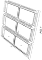
- Figure 1 illustrates an arrangement in which the first and second embodiments are both implemented in the same roofing structure. This will be discussed later.
- the first embodiment is directed to an arrangement in which there is no gutter between two solar panel modules 1.
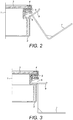
- FIGS 2 to 5 illustrate a solar panel module 1 having a solar panel connector 2.
- a photovoltaic glass sheet 3 of a solar panel may attach to the solar panel connector 2 in a recess/slot on a first side of the solar panel connector 2.
- the attachment point may comprise a sealant compound 4 with the aim of contributing to providing a weather tight seal for the solar panel module 1.
- the solar panel connector is provided with at least one further slot 6 on an opposite face/side to the first side of the solar panel connector 2.
- This further slot 6 is configured to accept a fixing bracket 7.
- Fixing bracket 7 is shown in an isometric orientation in Figure 11 .
- the fixing bracket is configured to have at least three portions.
- a first portion of the bracket is configured to be inserted into the further slot 6 (as shown in Figures 2 and 3 ) and fixed therewith.
- One way of fixing the first portion of the bracket 7 to the further slot 6 is by simply fixing the two components together using screws or the like.
- the first portion of the bracket 7 is configured to be fixed to the further slot 6 by being rotatably inserted into the further slot 6.
- the further slot 6 of the solar panel connector comprises retaining means configured to, once the first portion of the bracket has been rotatably inserted, lock onto the first portion so that that the solar panel connector 2 and the bracket 7 are slidably connected to each other.
- the solar panel connector 2 and the bracket 7 are attached to each other in such a way that they may move laterally relative to each other only along a first axis.
- the bracket 7 is configured to retain the solar panel perpendicular to the top face and perpendicular to the solar panel side, but not in a sliding direction parallel to the side of the solar panel.
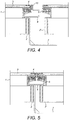
- the fixing bracket 7 further comprises a second portion 9.
- This second portion protrudes away from (i.e. in an opposite direction to) the first portion and presents a face for providing a guide to a second solar panel connector 2' (see Figures 4 and 5 ).
- the guide is usable by the second solar panel connector 2' for sliding the second solar panel connector 2' along the second portion in the direction of the first axis.
- the second solar panel connector 2' is configured to use a face of the bracket as a guide along the length of the bracket to locate and/or orientate the second solar panel connector 2' with respect to the first solar panel connector 2.
- the offset is zero.
- a face of the first portion and a face of the second portion of the bracket 7 are configured to respectively contact faces on the first and second solar panel connectors for holding the first and second solar panels in configurations in which the solar panel connectors 2, 2' may be slid along the same plane, as well as along the same axis (although it is understood that this is not essential).
- the bracket 7 may be said to cause the respective connection points between the bracket and the first and second portions to align vertically.
- the fixing bracket further comprises a third portion, separated from the first and second portions of the bracket by a leg.
- the third portion is a base portion and is configured for attachment to a part of a roofing structure, such as a roof beam or a tile batten.
- the leg is perpendicular to the third portion.
- the third portion of the bracket is shown as being substantially parallel to the first and second portions of the bracket. In use, the bracket can be fixed (using, for example, fixing means such as screws) to the roof structure below.
- the first portion of the bracket 7 comprises a protruding element, shaped to have a leading edge that angles upwards (perpendicularly to the third portion) to ensure a smooth interface as the first solar panel connector is slid into location.
- the second portion of the bracket 7 comprises a protruding element 9, shaped to have a leading edge that angles upwards (perpendicularly to the third portion) to ensure a smooth interface as the second solar panel is slid into location.
- the solar panel connector 2 further comprises a second slot/recess 5 on the same side as of the solar panel connector as the further slot/recess 6.
- the second slot/recess 5 is located above the further slot/recess 6.
- the second slot/recess 5 is shaped to receive retaining means, such as a flexible gasket, for retaining a sheet of flashing 10.
- the retaining means in the second slot/recess 5 may be a generally U-shaped section formed with a series of lips extending into the centre, such that when a thin sheet of material is pushed into it, they are deflected to form a series of seals against the upper and lower faces of the sheet of flashing 10.
- the roofing system also comprises flashing 10 for creating a weather-tight seal between the two close-coupled solar panels.
- this is a thin rectangular strip of a length that exceeds the length of the side of the panel that is to be close coupled and a width sufficient to push into the retaining means in the second slot/recess 5 on both solar panel connectors.
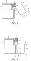
- the flashing 10 can be pushed into the retaining means of the second slot/recess 5 of the solar panel connector 2 along one side of the first solar panel connector (as shown in Figure 4 ).
- an unrestrained end of the flashing protrudes in the direction of the second solar panel connector in line with a corresponding retaining means in the second slot/recess of the second panel connector (as shown in Figures 4 and 5 ).
- One advantageous embodiment of the flashing can include a formed ridge 17 that extends along at least part of the length of the flashing to provide stiffness in handling and to reduce the depth between the top surface of the panel and the flashing, thus encouraging water (e.g. rain water) to be shed onto the panels and away from the gasket/solar panel connector-flashing interface. This is shown in Figure 13 .
- the second solar panel connector can be joined to the first solar panel connector to create a weather-tight seal between the two edges and to fix both solar panels modules to the roof structure below by the simple method of pushing the two together.
- a method of fixing together the components of the first embodiment may therefore be considered to be as follows.
- a first portion 8 of bracket 7 is fixed to a second portion of a solar panel connector 2 (that is part of a solar module).
- One way of fixing the first portion of the bracket 7 to the second portion of the solar panel connector 2 is by simply fixing the two components together using screws, or some other fixing means.
- the first portion of the bracket 7 is configured to be fixed to the further slot 6 by being rotatably inserted into the further slot 6.
- at least one of the first portion 8 of the bracket 7 and the solar panel connector 2 are configured such that, after a minimum amount of rotation, the first portion 8 of the bracket 7 and the second portion of the solar panel connector 2 are rotatably locked onto each other. Instead, the only relative motion between the bracket 7 and the solar panel connector 2 is laterally and along a single axis.
- a third portion of the bracket 7 is used to attach the bracket 7 and the solar panel connector 2 to at least part of a roofing structure.
- a third step flashing is inserted into the first portion on the first solar panel connector 2, for creating a weatherproof seal therebetween.
- a second portion 9 of the bracket 7 is used as a guide to slide the second solar panel connector 2' of another solar module into position, adjacent to the first solar panel connector.
- the second portion 9 of the bracket 7 is such that the second solar panel connector is constrained (once slid onto the bracket) to move laterally along the first axis and to move laterally out of the second portion of the bracket.
- the second solar panel connector cannot, however, move up or down (relative) to the roof to which the system is being attached.
- the second solar panel module is constrained to be unable to move in a direction perpendicular to the face of its photovoltaic glass once slid onto the second portion of the bracket.
- a fifth step flashing is inserted into the first portion on the secondsolar panel connector 2', for creating a weatherproof seal therebetween.
- the fourth and the fifth step may be combined in a single operation.
- the presently described second embodiment provides for the attaching bracket to provide support for, and allow definition of, a gutter extending between adjacent solar panel connectors.
- the gutter is used to direct water to shed downwards at the corners where four panels meet.
- a photovoltaic glass sheet 3 of a solar panel may provide an attachment point to the solar panel connector 2 in a recess/slot on a first side of the solar panel connector 2.
- the attachment point may comprise a sealant compound 4 with the aim of contributing to providing a weather tight seal for the solar panel module 1.
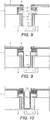
- the bracket 11 that is the focus of second embodiment is illustrated with respect to Figure 12 .
- the bracket 11 comprises three portions: a first portion 8 configured to engage with a second portion of a first solar panel connector 2, so that the first solar panel connector 2 and bracket 11 are slidably attached along a first axis; a second portion 9 configured to slidably engage with a second portion of a second solar panel connector; and a third (base) portion on which attachment means are provided for attaching to at least part of a roofing structure.
- the third portion is a base portion and is configured for attachment to a part of a roofing structure, such as a roof beam or a tile batten.
- the leg is perpendicular to the third portion.
- the third portion of the bracket is substantially parallel to the first and second portions of the bracket.
- the bracket can be fixed (using, for example, fixing means such as screws) to the roof structure below.
- the bracket 11 of the second embodiment differs from the first embodiment in that the bracket is substantially U-shaped, with the base of the U-shape providing the third portion, and respective legs 12, 13 of the U-shape corresponding to the first and second portions.
- the distance between the legs 12, 13 of the U-shape defines a maximum size of a gutter area spanning between the legs of the U-shape of the bracket 11. This is better illustrated with respect to Figures 6 to 10 .
- the first portion of the bracket 11 of the second embodiment is being rotated into the second portion of the first solar panel connector 2 (this operation may also be viewed as the second portion of the first solar panel connector 2 being rotated onto a stationary/fixed bracket (depending on whether or not the bracket is already fixed to a roofing structure)).
- the rotation causes the bracket 11 and the first solar panel connector 2 to become slidably attached to each other such that the bracket 11 and the first solar panel connector 2 can only move laterally with respect to each other along a first axis.
- the first axis extends along the point of connection between the first portion of the bracket 11 and the second portion of the first solar panel connector. This operation results in the first solar panel connector being slidably attached to the bracket such that the first solar panels lateral movement (with respect to the bracket 11) is constrained along the first axis.
- a third portion (the base portion) of the bracket 11 may be used to attach the bracket 11 and the first solar panel connector/module to a roofing structure.
- the second solar panel connector may then be slid onto and along the second portion of the bracket 11 by means of using the second portion 9 of the bracket 11 as a guide (in particular, using a lower surface of the second portion 9 of the bracket 11 ("lower” is defined in use relative to a roof structure, as described in the general section below)).
- This operation results in the second solar panel connector being slidably attached to the bracket such that the second solar panels lateral movement (with respect to the bracket 11) is constrained along and to move out of the bracket.
- the second solar panel connector cannot, however, move up or down relative to the roof to which the system is being attached.
- the second solar panel connector 2' is configured to use a face of the bracket 11 as a guide along the length of the bracket to locate and/or orientate the second solar panel connector 2' with respect to the first solar panel connector 2.
- the offset is zero.
- the first portion of the bracket 11 may comprise a protruding element, shaped to have a leading edge that angles upwards (perpendicularly to the third portion) to ensure a smooth interface as the first solar panel connector is slid into location.
- the second portion of the bracket 11 may comprise a protruding element 9, shaped to have a leading edge that angles upwards (perpendicularly to the third portion 7) to ensure a smooth interface as the second solar panel is slid into location.
- the solar panel connector 2 further comprises a second slot/recess 5 on the same side as of the solar panel connector as the further slot/recess 6.
- the second slot/recess 5 is located above the further slot/recess 6.
- the second slot/recess 5 is shaped to receive retaining means, such as a flexible gasket, for retaining a sheet of flashing 15.
- the retaining means in the second slot/recess 5 may be a generally U-shaped section formed with a series of lips extending into the centre, such that when a thin sheet of material is pushed into it, they are deflected to form a series of seals against the upper and lower faces of the sheet of flashing 15.
- both the first and second solar panel connectors are set a fixed distance apart through use of the bracket 11, a gutter for the washing away of rainwater is thereby provided therebetween.
- a waterproof seal may be provided. This may be provided by use of two distinct components.
- One component is a U-shaped gutter element 14, configured so as to fit into the gap between the two sides of the bracket 11 as shown in Figure 9 .
- the U-shaped gutter elements may be configured so as to provide a light interference fit with the U-shaped bracket 11, thus grip the bracket 11 to prevent sliding.
- the other component is flashing 15.
- the flashing component 15 is provided by two separate L shaped covers 15.
- the flashing is configured to have at least one portion that protrudes into retaining located in a respective second slot/recess 5 in a respective solar panel connector.
- the connection between the flashing 15 and the second slot/recess of the solar panel connector is as described above with respect to the flashing 10 of the first embodiment.
- the remaining end 16 of the L-shaped flashing 15 is configured to bend into the U-shaped recess defined by the U-shaped guttering element 14. This arrangement is illustrated with respect to Figure 10 .
- a method of fixing together the components of the second embodiment may therefore be considered to be as follows.
- a first portion of bracket 11 is rotated onto a second portion of a solar panel connector (that is part of a solar module). At least one of the first portion of the bracket 11 and the solar panel connector 2 are configured such that, after a minimum amount of rotation, the first portion of the bracket 11 and the second portion of the solar panel connector 2 are rotatably locked onto each other. Instead, the only relative motion between the bracket 11 and the solar panel connector 2 is laterally and along a single axis.
- a third portion of the bracket 11 is used to attach to at least part of a roofing structure.
- a second portion 9 of the bracket 11 is used as a guide to slide the second solar panel connector 2' of another solar module into position, adjacent to the first solar panel connector.
- the second portion 9 of the bracket 11 is such that the second solar panel connector is constrained (once slid onto the bracket) to move laterally along the first axis and to move laterally out of the second portion of the bracket.
- the second solar panel connector cannot, however, move up or down (relative) to the roof to which the system is being attached.
- the second solar panel module is constrained to be unable to move in a direction perpendicular to the face of its photovoltaic glass once slid onto the second portion of the bracket.
- a U-shaped gutter component is inserted in the bracket 11, between the first and second solar panel connectors.
- the U-shaped gutter component defines a channel for receiving water and for draining the water towards the edges of the roof to which the components are attached.
- respective L-shaped flashing components 15 are inserted into respective first portions on the first and second solar panel connectors, for establishing a weatherproof seal therebetween.
- Figure 1 shows an array of solar modules connected together.
- the isometric view appears from the top (defined with respect to a position of the solar modules when fixed to a roof. Consequently, aside from the solar modules, the flashings 10 and 15 are also viewable, as are gutter components 14 of the second embodiment, where flashing 10 corresponds to the flashing in the first embodiment and flashing 15 corresponds to the flashing in the second embodiment.
- the flashings 10 are arranged to extend along the length of a roof, whilst the flashings 15 and gutter components 15 are arranged to extend along the slope of the roof. This arrangement allows the channels defined by the gutter components 15 and the flashings 14 to run any incident rainwater off the roof efficiently, under the effect of gravity.
- the solar panel connector 2 may be of extruded aluminium that is cut and joined at four corners to hold a photovoltaic glass cover sheet 3.
- the sealant compound may be silicone 4.
- gasket examples include rubber and EPDM. It can be formed by extrusion, and joined with moulded mitred corners to form a continuous loop.
- length of a component is the magnitude of its largest dimension.
Landscapes
- Engineering & Computer Science (AREA)
- General Engineering & Computer Science (AREA)
- Mechanical Engineering (AREA)
- Sustainable Development (AREA)
- Sustainable Energy (AREA)
- Thermal Sciences (AREA)
- Chemical & Material Sciences (AREA)
- Combustion & Propulsion (AREA)
- Physics & Mathematics (AREA)
- Life Sciences & Earth Sciences (AREA)
- Architecture (AREA)
- Civil Engineering (AREA)
- Structural Engineering (AREA)
- Roof Covering Using Slabs Or Stiff Sheets (AREA)
Applications Claiming Priority (1)
| Application Number | Priority Date | Filing Date | Title |
|---|---|---|---|
| GB1515708.4A GB2541927A (en) | 2015-09-04 | 2015-09-04 | Photovoltaic roof covering |
Publications (4)
| Publication Number | Publication Date |
|---|---|
| EP3205952A2 true EP3205952A2 (de) | 2017-08-16 |
| EP3205952A3 EP3205952A3 (de) | 2017-11-15 |
| EP3205952B1 EP3205952B1 (de) | 2024-04-17 |
| EP3205952C0 EP3205952C0 (de) | 2024-04-17 |
Family
ID=54345785
Family Applications (1)
| Application Number | Title | Priority Date | Filing Date |
|---|---|---|---|
| EP16187008.4A Active EP3205952B1 (de) | 2015-09-04 | 2016-09-02 | Fotovoltaische dachabdeckung |
Country Status (3)
| Country | Link |
|---|---|
| US (1) | US10277161B2 (de) |
| EP (1) | EP3205952B1 (de) |
| GB (1) | GB2541927A (de) |
Families Citing this family (8)
| Publication number | Priority date | Publication date | Assignee | Title |
|---|---|---|---|---|
| GB201905849D0 (en) * | 2019-04-26 | 2019-06-12 | Roof Tiles Tech Limited | Photovoltaic roof covering and method of manufacture |
| CN113498578B (zh) * | 2020-02-07 | 2025-06-03 | 詹姆斯·袁 | 太阳能板和带有边缘连接器的轨道 |
| US12339040B2 (en) | 2022-11-23 | 2025-06-24 | Sunmodo Corporation | Rail-less solar panel devices and system for roofs and the like and methods for mounting same |
| EP4534774A1 (de) * | 2023-10-02 | 2025-04-09 | VKR Holding A/S | Dachfenster mit einem rahmen mit einer dichtungsmuffe und einem dichtungselement sowie verfahren zur abdichtung einer verbindung zwischen einem dachfenster und einer dachstruktur |
| GB2638658A (en) * | 2024-01-10 | 2025-09-03 | Senergy Innovations Ltd | In-roof solar-thermal-panel frame and system |
| US12149200B1 (en) | 2024-07-03 | 2024-11-19 | Sunmodo Corporation | Railless mounting system and devices for attaching solar modules to roofs |
| US12231076B1 (en) | 2024-09-04 | 2025-02-18 | Sunmodo Corporation | Rail-less mounting system and devices for attaching solar modules to roofs |
| US12286994B1 (en) | 2024-09-09 | 2025-04-29 | Sunmodo Corporation | Railless mounting devices for securing solar modules to roofs |
Family Cites Families (20)
| Publication number | Priority date | Publication date | Assignee | Title |
|---|---|---|---|---|
| US4123883A (en) * | 1977-02-28 | 1978-11-07 | Sunworks, Inc. | Solar energy collector |
| WO2002041407A1 (fr) * | 2000-11-16 | 2002-05-23 | Kaneka Corporation | Module de batterie solaire, systeme de production d'energie photovoltaique, bloc de support supportant ce module de batterie solaire, et procede d'installation d'un systeme de production d'energie photovoltaique |
| US7434362B2 (en) * | 2001-07-20 | 2008-10-14 | Unirac, Inc. | System for removably and adjustably mounting a device on a surface |
| US7600349B2 (en) * | 2003-02-26 | 2009-10-13 | Unirac, Inc. | Low profile mounting system |
| GB2430943B (en) | 2005-09-21 | 2010-08-04 | Viridian Concepts Ltd | Roof flashing connections comprising resilient member |
| JP2008214875A (ja) * | 2007-02-28 | 2008-09-18 | Sharp Corp | 太陽電池モジュールの取付け構造 |
| JP4290750B2 (ja) * | 2007-06-11 | 2009-07-08 | 株式会社屋根技術研究所 | 太陽電池モジュールの固定構造、太陽電池モジュール用のフレーム及び固定部材 |
| JP4990367B2 (ja) * | 2007-10-03 | 2012-08-01 | 京セラ株式会社 | 太陽電池アレイ |
| DE102008006106B4 (de) * | 2008-01-25 | 2012-09-20 | Solarmarkt Ag | Solarmodul-Befestigungssystem |
| JP4365450B1 (ja) * | 2009-05-01 | 2009-11-18 | 株式会社屋根技術研究所 | 太陽電池モジュールの固定構造、太陽電池モジュール用のフレーム及び固定部材 |
| DE102009060786A1 (de) * | 2009-12-21 | 2011-06-22 | Rikker Holzbau GmbH, 71563 | Montagesystem für Photovoltaik-Module mit integrierter thermischer Solaranlage |
| US8181402B2 (en) * | 2010-04-01 | 2012-05-22 | Yanegijutsukenkyujo Co., Ltd. | Building-integrated photovoltaic power unit |
| US8495839B2 (en) * | 2010-04-01 | 2013-07-30 | Yanegijutsukenkyujo Co., Ltd. | Installation structure of solar cell module |
| JP5501125B2 (ja) | 2010-07-06 | 2014-05-21 | 株式会社屋根技術研究所 | 固定部材 |
| EP2447621A1 (de) * | 2010-11-01 | 2012-05-02 | Ingenieurbüro Minthe | Gestellsystem zur Montage von Solarmodulen |
| AT12772U1 (de) * | 2011-03-07 | 2012-11-15 | Inova Lisec Technologiezentrum | Anordnung aus photovoltaik-modulen |
| EP2520876B1 (de) * | 2011-05-04 | 2013-04-03 | V-Energie S.r.L. | Bausatz zur Herstellung eines photovoltaischen Daches |
| US9698724B2 (en) * | 2011-12-13 | 2017-07-04 | Solarcity Corporation | Connecting components for photovoltaic arrays |
| US9010041B2 (en) * | 2012-06-25 | 2015-04-21 | Sunpower Corporation | Leveler for solar module array |
| WO2014016882A1 (ja) * | 2012-07-23 | 2014-01-30 | 株式会社屋根技術研究所 | 太陽電池モジュールの固定構造 |
-
2015
- 2015-09-04 GB GB1515708.4A patent/GB2541927A/en not_active Withdrawn
-
2016
- 2016-09-02 EP EP16187008.4A patent/EP3205952B1/de active Active
- 2016-09-02 US US15/255,686 patent/US10277161B2/en active Active
Also Published As
| Publication number | Publication date |
|---|---|
| US20170070182A1 (en) | 2017-03-09 |
| EP3205952A3 (de) | 2017-11-15 |
| EP3205952B1 (de) | 2024-04-17 |
| EP3205952C0 (de) | 2024-04-17 |
| GB2541927A (en) | 2017-03-08 |
| GB201515708D0 (en) | 2015-10-21 |
| US10277161B2 (en) | 2019-04-30 |
Similar Documents
| Publication | Publication Date | Title |
|---|---|---|
| EP3205952B1 (de) | Fotovoltaische dachabdeckung | |
| JP4290750B2 (ja) | 太陽電池モジュールの固定構造、太陽電池モジュール用のフレーム及び固定部材 | |
| EP3092350B1 (de) | Schienenloses dachmontagesystem | |
| CA3070451C (en) | Panel, assembly of panels, and associated roof | |
| KR20070114065A (ko) | 태양광 지붕 타일 | |
| EP2461120B1 (de) | Verbindungssystem und Verfahren zur Errichtung eines wetterfesten Sonnenkollektor-Verbunds als Teil eines Daches | |
| JP2018511721A (ja) | 傾斜屋根用太陽光パネル装着システム | |
| KR20120120201A (ko) | 고정부재 | |
| JP7324214B2 (ja) | 太陽電池パネルの設置構造 | |
| US20170155355A1 (en) | Interlock system for mounting and joining photovoltaic modules | |
| EP2192248A1 (de) | Dachkomponentenabdichtung, ein Dachabdichtungssystem und eine Methode. | |
| KR102138147B1 (ko) | 태양광모듈이 적용된 끼움 결합식 지붕플레이트 조립체 | |
| US9528266B2 (en) | Dual glazing panel system | |
| GB2497276A (en) | Panel roofing frame with hook and click connection | |
| JP6746369B2 (ja) | 太陽電池モジュール | |
| JP2000204733A (ja) | 屋根一体型太陽電池アレイ | |
| JP4093839B2 (ja) | 太陽電池モジュールの屋根取付け構造体及び太陽電池アレイ | |
| CN110778031A (zh) | Bipv防水系统 | |
| CN222575969U (zh) | 用于在两个屋顶窗户之间使用的防水组件以及一组屋顶窗户 | |
| CN210780636U (zh) | 全结构式防水光伏支架 | |
| US20240275330A1 (en) | Photovoltaic profile, photovoltaic roof tile module and photovoltaic roof installation system | |
| EP1990585A1 (de) | Montageadapter für Solardachziegel | |
| JP2020094409A (ja) | 遮光システム、遮光金具および遮光システムの施工方法 | |
| JP4112775B2 (ja) | 上屋の構造 | |
| CN211341455U (zh) | Bipv防水系统 |
Legal Events
| Date | Code | Title | Description |
|---|---|---|---|
| PUAI | Public reference made under article 153(3) epc to a published international application that has entered the european phase |
Free format text: ORIGINAL CODE: 0009012 |
|
| STAA | Information on the status of an ep patent application or granted ep patent |
Free format text: STATUS: THE APPLICATION HAS BEEN PUBLISHED |
|
| AK | Designated contracting states |
Kind code of ref document: A2 Designated state(s): AL AT BE BG CH CY CZ DE DK EE ES FI FR GB GR HR HU IE IS IT LI LT LU LV MC MK MT NL NO PL PT RO RS SE SI SK SM TR |
|
| AX | Request for extension of the european patent |
Extension state: BA ME |
|
| PUAL | Search report despatched |
Free format text: ORIGINAL CODE: 0009013 |
|
| AK | Designated contracting states |
Kind code of ref document: A3 Designated state(s): AL AT BE BG CH CY CZ DE DK EE ES FI FR GB GR HR HU IE IS IT LI LT LU LV MC MK MT NL NO PL PT RO RS SE SI SK SM TR |
|
| AX | Request for extension of the european patent |
Extension state: BA ME |
|
| RIC1 | Information provided on ipc code assigned before grant |
Ipc: F24J 2/52 20060101AFI20171010BHEP |
|
| STAA | Information on the status of an ep patent application or granted ep patent |
Free format text: STATUS: REQUEST FOR EXAMINATION WAS MADE |
|
| 17P | Request for examination filed |
Effective date: 20180515 |
|
| RBV | Designated contracting states (corrected) |
Designated state(s): AL AT BE BG CH CY CZ DE DK EE ES FI FR GB GR HR HU IE IS IT LI LT LU LV MC MK MT NL NO PL PT RO RS SE SI SK SM TR |
|
| STAA | Information on the status of an ep patent application or granted ep patent |
Free format text: STATUS: EXAMINATION IS IN PROGRESS |
|
| 17Q | First examination report despatched |
Effective date: 20190409 |
|
| REG | Reference to a national code |
Ref country code: DE Ref legal event code: R079 Free format text: PREVIOUS MAIN CLASS: F24J0002520000 Ipc: F24S0080700000 Ref country code: DE Ref legal event code: R079 Ref document number: 602016086949 Country of ref document: DE Free format text: PREVIOUS MAIN CLASS: F24J0002520000 Ipc: F24S0080700000 |
|
| GRAP | Despatch of communication of intention to grant a patent |
Free format text: ORIGINAL CODE: EPIDOSNIGR1 |
|
| STAA | Information on the status of an ep patent application or granted ep patent |
Free format text: STATUS: GRANT OF PATENT IS INTENDED |
|
| RIC1 | Information provided on ipc code assigned before grant |
Ipc: F24S 25/20 20180101ALI20231006BHEP Ipc: F24S 25/35 20180101ALI20231006BHEP Ipc: F24S 20/67 20180101ALI20231006BHEP Ipc: F24S 80/70 20180101AFI20231006BHEP |
|
| INTG | Intention to grant announced |
Effective date: 20231113 |
|
| RAP3 | Party data changed (applicant data changed or rights of an application transferred) |
Owner name: VIRIDIAN SOLAR LIMITED |
|
| GRAS | Grant fee paid |
Free format text: ORIGINAL CODE: EPIDOSNIGR3 |
|
| GRAA | (expected) grant |
Free format text: ORIGINAL CODE: 0009210 |
|
| STAA | Information on the status of an ep patent application or granted ep patent |
Free format text: STATUS: THE PATENT HAS BEEN GRANTED |
|
| AK | Designated contracting states |
Kind code of ref document: B1 Designated state(s): AL AT BE BG CH CY CZ DE DK EE ES FI FR GB GR HR HU IE IS IT LI LT LU LV MC MK MT NL NO PL PT RO RS SE SI SK SM TR |
|
| REG | Reference to a national code |
Ref country code: GB Ref legal event code: FG4D |
|
| REG | Reference to a national code |
Ref country code: CH Ref legal event code: EP |
|
| REG | Reference to a national code |
Ref country code: DE Ref legal event code: R096 Ref document number: 602016086949 Country of ref document: DE |
|
| REG | Reference to a national code |
Ref country code: IE Ref legal event code: FG4D |
|
| U01 | Request for unitary effect filed |
Effective date: 20240517 |
|
| U07 | Unitary effect registered |
Designated state(s): AT BE BG DE DK EE FI FR IT LT LU LV MT NL PT SE SI Effective date: 20240528 |
|
| U20 | Renewal fee for the european patent with unitary effect paid |
Year of fee payment: 9 Effective date: 20240815 |
|
| PG25 | Lapsed in a contracting state [announced via postgrant information from national office to epo] |
Ref country code: IS Free format text: LAPSE BECAUSE OF FAILURE TO SUBMIT A TRANSLATION OF THE DESCRIPTION OR TO PAY THE FEE WITHIN THE PRESCRIBED TIME-LIMIT Effective date: 20240817 |
|
| PG25 | Lapsed in a contracting state [announced via postgrant information from national office to epo] |
Ref country code: HR Free format text: LAPSE BECAUSE OF FAILURE TO SUBMIT A TRANSLATION OF THE DESCRIPTION OR TO PAY THE FEE WITHIN THE PRESCRIBED TIME-LIMIT Effective date: 20240417 |
|
| PG25 | Lapsed in a contracting state [announced via postgrant information from national office to epo] |
Ref country code: GR Free format text: LAPSE BECAUSE OF FAILURE TO SUBMIT A TRANSLATION OF THE DESCRIPTION OR TO PAY THE FEE WITHIN THE PRESCRIBED TIME-LIMIT Effective date: 20240718 |
|
| PG25 | Lapsed in a contracting state [announced via postgrant information from national office to epo] |
Ref country code: ES Free format text: LAPSE BECAUSE OF FAILURE TO SUBMIT A TRANSLATION OF THE DESCRIPTION OR TO PAY THE FEE WITHIN THE PRESCRIBED TIME-LIMIT Effective date: 20240417 |
|
| PG25 | Lapsed in a contracting state [announced via postgrant information from national office to epo] |
Ref country code: PL Free format text: LAPSE BECAUSE OF FAILURE TO SUBMIT A TRANSLATION OF THE DESCRIPTION OR TO PAY THE FEE WITHIN THE PRESCRIBED TIME-LIMIT Effective date: 20240417 |
|
| PG25 | Lapsed in a contracting state [announced via postgrant information from national office to epo] |
Ref country code: PL Free format text: LAPSE BECAUSE OF FAILURE TO SUBMIT A TRANSLATION OF THE DESCRIPTION OR TO PAY THE FEE WITHIN THE PRESCRIBED TIME-LIMIT Effective date: 20240417 Ref country code: NO Free format text: LAPSE BECAUSE OF FAILURE TO SUBMIT A TRANSLATION OF THE DESCRIPTION OR TO PAY THE FEE WITHIN THE PRESCRIBED TIME-LIMIT Effective date: 20240717 Ref country code: IS Free format text: LAPSE BECAUSE OF FAILURE TO SUBMIT A TRANSLATION OF THE DESCRIPTION OR TO PAY THE FEE WITHIN THE PRESCRIBED TIME-LIMIT Effective date: 20240817 Ref country code: HR Free format text: LAPSE BECAUSE OF FAILURE TO SUBMIT A TRANSLATION OF THE DESCRIPTION OR TO PAY THE FEE WITHIN THE PRESCRIBED TIME-LIMIT Effective date: 20240417 Ref country code: GR Free format text: LAPSE BECAUSE OF FAILURE TO SUBMIT A TRANSLATION OF THE DESCRIPTION OR TO PAY THE FEE WITHIN THE PRESCRIBED TIME-LIMIT Effective date: 20240718 Ref country code: ES Free format text: LAPSE BECAUSE OF FAILURE TO SUBMIT A TRANSLATION OF THE DESCRIPTION OR TO PAY THE FEE WITHIN THE PRESCRIBED TIME-LIMIT Effective date: 20240417 Ref country code: RS Free format text: LAPSE BECAUSE OF FAILURE TO SUBMIT A TRANSLATION OF THE DESCRIPTION OR TO PAY THE FEE WITHIN THE PRESCRIBED TIME-LIMIT Effective date: 20240717 |
|
| REG | Reference to a national code |
Ref country code: DE Ref legal event code: R097 Ref document number: 602016086949 Country of ref document: DE |
|
| PG25 | Lapsed in a contracting state [announced via postgrant information from national office to epo] |
Ref country code: CZ Free format text: LAPSE BECAUSE OF FAILURE TO SUBMIT A TRANSLATION OF THE DESCRIPTION OR TO PAY THE FEE WITHIN THE PRESCRIBED TIME-LIMIT Effective date: 20240417 |
|
| PG25 | Lapsed in a contracting state [announced via postgrant information from national office to epo] |
Ref country code: SK Free format text: LAPSE BECAUSE OF FAILURE TO SUBMIT A TRANSLATION OF THE DESCRIPTION OR TO PAY THE FEE WITHIN THE PRESCRIBED TIME-LIMIT Effective date: 20240417 Ref country code: RO Free format text: LAPSE BECAUSE OF FAILURE TO SUBMIT A TRANSLATION OF THE DESCRIPTION OR TO PAY THE FEE WITHIN THE PRESCRIBED TIME-LIMIT Effective date: 20240417 |
|
| PG25 | Lapsed in a contracting state [announced via postgrant information from national office to epo] |
Ref country code: SM Free format text: LAPSE BECAUSE OF FAILURE TO SUBMIT A TRANSLATION OF THE DESCRIPTION OR TO PAY THE FEE WITHIN THE PRESCRIBED TIME-LIMIT Effective date: 20240417 |
|
| PG25 | Lapsed in a contracting state [announced via postgrant information from national office to epo] |
Ref country code: SM Free format text: LAPSE BECAUSE OF FAILURE TO SUBMIT A TRANSLATION OF THE DESCRIPTION OR TO PAY THE FEE WITHIN THE PRESCRIBED TIME-LIMIT Effective date: 20240417 Ref country code: SK Free format text: LAPSE BECAUSE OF FAILURE TO SUBMIT A TRANSLATION OF THE DESCRIPTION OR TO PAY THE FEE WITHIN THE PRESCRIBED TIME-LIMIT Effective date: 20240417 Ref country code: RO Free format text: LAPSE BECAUSE OF FAILURE TO SUBMIT A TRANSLATION OF THE DESCRIPTION OR TO PAY THE FEE WITHIN THE PRESCRIBED TIME-LIMIT Effective date: 20240417 Ref country code: CZ Free format text: LAPSE BECAUSE OF FAILURE TO SUBMIT A TRANSLATION OF THE DESCRIPTION OR TO PAY THE FEE WITHIN THE PRESCRIBED TIME-LIMIT Effective date: 20240417 |
|
| PLBE | No opposition filed within time limit |
Free format text: ORIGINAL CODE: 0009261 |
|
| STAA | Information on the status of an ep patent application or granted ep patent |
Free format text: STATUS: NO OPPOSITION FILED WITHIN TIME LIMIT |
|
| 26N | No opposition filed |
Effective date: 20250120 |
|
| PG25 | Lapsed in a contracting state [announced via postgrant information from national office to epo] |
Ref country code: MC Free format text: LAPSE BECAUSE OF FAILURE TO SUBMIT A TRANSLATION OF THE DESCRIPTION OR TO PAY THE FEE WITHIN THE PRESCRIBED TIME-LIMIT Effective date: 20240417 |
|
| REG | Reference to a national code |
Ref country code: CH Ref legal event code: PL |
|
| PG25 | Lapsed in a contracting state [announced via postgrant information from national office to epo] |
Ref country code: CH Free format text: LAPSE BECAUSE OF NON-PAYMENT OF DUE FEES Effective date: 20240930 |
|
| PG25 | Lapsed in a contracting state [announced via postgrant information from national office to epo] |
Ref country code: IE Free format text: LAPSE BECAUSE OF NON-PAYMENT OF DUE FEES Effective date: 20240902 |
|
| U20 | Renewal fee for the european patent with unitary effect paid |
Year of fee payment: 10 Effective date: 20250814 |
|
| PGFP | Annual fee paid to national office [announced via postgrant information from national office to epo] |
Ref country code: GB Payment date: 20250702 Year of fee payment: 10 |