EP3205811A1 - Plateau pour une échelle et une échelle avec ce plateau - Google Patents
Plateau pour une échelle et une échelle avec ce plateau Download PDFInfo
- Publication number
- EP3205811A1 EP3205811A1 EP17155209.4A EP17155209A EP3205811A1 EP 3205811 A1 EP3205811 A1 EP 3205811A1 EP 17155209 A EP17155209 A EP 17155209A EP 3205811 A1 EP3205811 A1 EP 3205811A1
- Authority
- EP
- European Patent Office
- Prior art keywords
- tray
- plug
- receptacle
- buckle
- hook
- Prior art date
- Legal status (The legal status is an assumption and is not a legal conclusion. Google has not performed a legal analysis and makes no representation as to the accuracy of the status listed.)
- Granted
Links
- 230000037431 insertion Effects 0.000 claims description 10
- 238000003780 insertion Methods 0.000 claims description 10
- 240000004050 Pentaglottis sempervirens Species 0.000 description 1
- 235000004522 Pentaglottis sempervirens Nutrition 0.000 description 1
- 244000007853 Sarothamnus scoparius Species 0.000 description 1
- 230000005489 elastic deformation Effects 0.000 description 1
- 239000006223 plastic coating Substances 0.000 description 1
Images


Classifications
-
- E—FIXED CONSTRUCTIONS
- E06—DOORS, WINDOWS, SHUTTERS, OR ROLLER BLINDS IN GENERAL; LADDERS
- E06C—LADDERS
- E06C7/00—Component parts, supporting parts, or accessories
- E06C7/14—Holders for pails or other equipment on or for ladders
-
- B—PERFORMING OPERATIONS; TRANSPORTING
- B25—HAND TOOLS; PORTABLE POWER-DRIVEN TOOLS; MANIPULATORS
- B25H—WORKSHOP EQUIPMENT, e.g. FOR MARKING-OUT WORK; STORAGE MEANS FOR WORKSHOPS
- B25H3/00—Storage means or arrangements for workshops facilitating access to, or handling of, work tools or instruments
- B25H3/06—Trays
-
- E—FIXED CONSTRUCTIONS
- E06—DOORS, WINDOWS, SHUTTERS, OR ROLLER BLINDS IN GENERAL; LADDERS
- E06C—LADDERS
- E06C7/00—Component parts, supporting parts, or accessories
- E06C7/18—Devices for preventing persons from falling
- E06C7/181—Additional gripping devices, e.g. handrails
- E06C7/182—Additional gripping devices, e.g. handrails situated at the top of the ladder
-
- E—FIXED CONSTRUCTIONS
- E06—DOORS, WINDOWS, SHUTTERS, OR ROLLER BLINDS IN GENERAL; LADDERS
- E06C—LADDERS
- E06C1/00—Ladders in general
- E06C1/02—Ladders in general with rigid longitudinal member or members
- E06C1/38—Special constructions of ladders, e.g. ladders with more or less than two longitudinal members, ladders with movable rungs or other treads, longitudinally-foldable ladders
- E06C1/39—Ladders having platforms; Ladders changeable into platforms
-
- E—FIXED CONSTRUCTIONS
- E06—DOORS, WINDOWS, SHUTTERS, OR ROLLER BLINDS IN GENERAL; LADDERS
- E06C—LADDERS
- E06C7/00—Component parts, supporting parts, or accessories
- E06C7/18—Devices for preventing persons from falling
- E06C7/186—Rail or rope for guiding a safety attachment, e.g. a fall arrest system
Definitions
- the present invention relates to a tray. Furthermore, the invention relates to a ladder with this tray.
- U1 is a step ladder with a tray known.
- the tray connects upper ends of bars of a riser of step ladder.
- the tray has various holes that can serve as receptacles for inserting tools such as screwdrivers or for inserting power tools such as electric screwdrivers or drills.
- a compartment is provided in which all kinds of items such as screws or other small parts can be stored.
- a so-called bucket hook is provided on which a bucket or other items can be attached or attached.
- the present invention is based on the object to propose a tray that allows greater flexibility and better protection of the attached items.
- the tray has a first receptacle for a part of a plug-in buckle, which can be attached to the tray.
- the tray has a plurality of second receptacles for hooks that can be attached to the tray.
- a plug-in buckle is a closure assembly such as that in the document DE 203 16 449 U1 is described. Usually plug-in closures are used to close belt connections. Plug closure are used in particular on bags to close the lid of a bag.
- the first receptacle of a storage tray according to the invention may be a through hole. At least one stop for the first part of the plug-in buckle can be arranged in this through-hole. With the help of the stopper, a simple positioning of the first part of the plug-in buckle is possible.
- the first part may be a male plug-in closure part.
- the first part of the plug-in buckle can be inserted from a first side of the tray into the first receptacle.
- the first receptacle is further configured such that a second part of the plug-in buckle can be inserted from a second side of the storage tray into the first receptacle.
- This second part of the plug-in buckle may be a female plug-in closure part.
- the tray has transversely to the first receptacle at least a first hole through which a securing means for securing the first part of the plug-in buckle is inserted into the first receptacle.
- the second receptacles of a storage tray according to the invention may have, at least in sections, a non-circular first cross-sectional area.
- This non-circular cross-sectional area makes it necessary that a hook can be inserted into the second receptacle only in a certain position and removed from the second receptacle, whereby a random falling out of the hooks from the second receptacles is made more difficult.
- At least one of the second receptacles may have a take-up direction that is aligned parallel to an upper surface of the storage tray. Likewise, at least one of the second receptacles have a receiving direction, which is aligned perpendicular to the top of the tray. This makes it possible to attach hooks in different positions on the tray.
- a first part of the plug-in buckle may be attached to a first end of the belt and the first part of the plug-in buckle may be inserted from the first side of the tray in the first receptacle of the tray.
- the first part of the plug-in buckle can be fastened to the abutment.
- the arrangement may comprise a securing means, for example a pin or a bow or a split pin, which passes through the at least one first hole in the tray into a recess is inserted in the first part of the plug-in buckle, to secure the first part of the plug-in buckle against being pulled out of the first receptacle.
- a securing means for example a pin or a bow or a split pin, which passes through the at least one first hole in the tray into a recess is inserted in the first part of the plug-in buckle, to secure the first part of the plug-in buckle against being pulled out of the first receptacle.
- a second part of the plug-in buckle is attached to a second end of the belt.
- the first and second ends of the belt may be connected together to form a loop.
- this loop objects can be hung or secured to the tray or a hook on the tray suspended objects are secured.
- the hook may have a plug-in portion which is inserted in one of the second receptacles.
- the male portion of the hook may have a cross-sectional area at at least one location or in an area corresponding to the first cross-sectional area of the second seats.
- the insertion portion of the hook and the second recordings act like a key and a lock together, so that the hook can be used in only one or a few positions in the second recordings and removed again from the second recordings.
- the hook of an arrangement according to the invention can be angled approximately 90 ° to the insertion portion having an intermediate portion and angled approximately 90 ° to the intermediate portion having a hook portion, wherein the intermediate portion connects the male portion and the hook portion.
- This double bend has the advantage that the hook portion are pivoted in a large angular range can take to different positions relative to the tray.
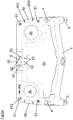
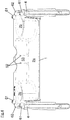
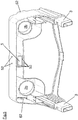
- the tray A shown in the figures has many elements, as they already from the tray of step ladder from the document DE 20 2007 002 103 U1 are known.
- the tray has u.a. two sockets 3, with which the tray can be inserted into upper ends of bars of a riser of a step ladder and attached to these upper ends of the spars.
- the two sockets 3 are connected by a central region 1, in which a compartment 2a is provided for the storage of objects.
- two circular through holes 2b are provided which can serve as receptacles for hand tool machines, for example for a cordless screwdriver.
- the tray on two known through holes 4, which can accommodate rods 7 of a bracket 7, 8, which is slidably guided in the bars of step ladder, which in itself from the document DE 20 2007 002 103 U1 is known.
- the document is DE 20 2007 002 103 U1 directed.
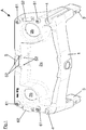
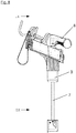
- the storage tray has a first receptacle 5. This is formed by a through hole extending from an upper side to a Bottom of the tray A extends and has a substantially rectangular cross-section.
- a plug-in buckle S in the first receptacle 5 is arranged.
- a first part S1 of the plug-in buckle S is fastened in the receptacle 5.
- first part S1 of the plug-in buckle S is the male part of the plug-in buckle S
- a securing is possible in that two outwardly curved tines S10 of the first plug-in closing part S1 are pressed inwards when inserting the male plug-in closing part S1 Stop 50 to be moved past, which is arranged in the first receptacle 5.
- a shoulder S11 of the first plug-in closure part S1 can come into abutment against the stop 50.
- the first plug-in closure part S1 of the illustrated embodiment is inserted from below into the first recess 5.
- two smaller through holes 52 are provided at a distance from each other, which extend through the first receptacle 5 bounding walls 53 of the tray A.
- the through-holes 52 also extend through a wall 53 delimiting the compartment 2 and a wall 53 on the back of the storage tray.
- the first part S1 of the plug-in buckle S inserted in the first receptacle 5 has through-holes or a continuous slot S12. Legs of a U-shaped bracket K can be inserted through these holes or the slot S12 in the first part S1 of the plug-in buckle S and the through-holes 52 in the region of the first receptacle 5 in order to secure the first part S1 of the plug-in buckle S in the receptacle 5 ,
- a first end of a belt G is attached.
- a second plug-in closure part S2 is attached, in the present example, the female plug closure part.
- This second plug-in closure part S2 has a receptacle into which the prongs S10 of the first plug-in closure part S1 can be inserted and latched in a manner known per se.
- the second part S2 of the plug-in buckle S can be inserted from above into the first receptacle 5 of the storage tray A and plugged onto the prongs S10 of the first part S1 of the plug-in buckle S.
- the belt G then forms a loop with which objects can be hung and secured.
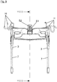
- the tray A also has second receptacles 61, 62 for hooks H, which can be attached to the tray A.
- the second receptacles 61, 62 there are four second receptacles 61, which have a receiving direction for the hooks H perpendicular to the top of the tray A.
- Two further second receptacles 62 have a receiving direction, which runs parallel to the top of the tray A. This makes it possible to attach hooks H differently oriented on the tray A.
- the two second second receptacles 62 are aligned so that a tool handle, for example the broomstick of a broom, can be hung by means of the hook H. as known in the art.
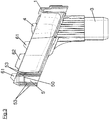
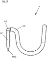
- the second receptacles 61, 62 have at least in a region 610, 620 a first cross-sectional area, which is not circular (see in particular Fig. 2a , second pictures 61, 62).
- This first cross-sectional area is chosen so that it is adapted to a region H10 with a first cross-sectional area of a plug-in portion H1 of the hooks H.
- the insertion portion H1 has this first cross-sectional area in the region H10, which is first inserted into the second receptacles 61, 62 when one of the hooks H in the second receptacle 61, 62 attached.
- This end portion H1 having the first cross-sectional area cooperates with the portion 610, 620 of the second receptacles 61, 62 having the first cross-sectional area similar to a key and a keyhole.
- An insertion is possible only in certain positions.
- a release of the hook ie a withdrawal of the insertion of the hook only in certain positions possible.
- a random falling out is not completely prevented, but at least severely limited.
- the first cross-sectional area in the end portion H10 of the Einsteckabitess H1 additionally has a slight excess, and the Einstecksteck Scheme H1 can be used only with a slight elastic deformation in the second receptacles 61, 62. Also by the hook H is secured against accidental falling out.
- the second second receptacles 62 can have a region 620 with a first cross-sectional area both in an initial region and in an end region (viewed in the insertion direction of the insertion sections of the hook H).
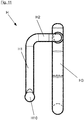
- the hooks H have in addition to the insertion portion H1 to an angled about 90 ° intermediate portion H2. This is in turn followed by 90 ° angled hook section H3, which is used for hanging or attaching the objects that at the Tray A should be attached.
- This hook portion H3 is bent substantially U-shaped and provided with a slip-resistant plastic coating.
Landscapes
- Engineering & Computer Science (AREA)
- Mechanical Engineering (AREA)
- Vehicle Step Arrangements And Article Storage (AREA)
- Purses, Travelling Bags, Baskets, Or Suitcases (AREA)
- Package Frames And Binding Bands (AREA)
- Ladders (AREA)
- Valve-Gear Or Valve Arrangements (AREA)
Applications Claiming Priority (1)
| Application Number | Priority Date | Filing Date | Title |
|---|---|---|---|
| DE202016100719.4U DE202016100719U1 (de) | 2016-02-12 | 2016-02-12 | Ablageschale für eine Leiter und Leiter mit dieser Ablageschale |
Publications (2)
| Publication Number | Publication Date |
|---|---|
| EP3205811A1 true EP3205811A1 (fr) | 2017-08-16 |
| EP3205811B1 EP3205811B1 (fr) | 2022-09-14 |
Family
ID=58009706
Family Applications (1)
| Application Number | Title | Priority Date | Filing Date |
|---|---|---|---|
| EP17155209.4A Active EP3205811B1 (fr) | 2016-02-12 | 2017-02-08 | Plateau pour une échelle et une échelle avec ce plateau |
Country Status (7)
| Country | Link |
|---|---|
| US (1) | US10087682B2 (fr) |
| EP (1) | EP3205811B1 (fr) |
| DE (1) | DE202016100719U1 (fr) |
| DK (1) | DK3205811T3 (fr) |
| ES (1) | ES2931398T3 (fr) |
| PL (1) | PL3205811T3 (fr) |
| PT (1) | PT3205811T (fr) |
Cited By (3)
| Publication number | Priority date | Publication date | Assignee | Title |
|---|---|---|---|---|
| CN108818484A (zh) * | 2018-01-22 | 2018-11-16 | 朱宰哲 | 摄像机模块制造用托盘 |
| EP3702575A1 (fr) | 2019-02-28 | 2020-09-02 | CDH Group | Tablette a reprise d'effort |
| USD984000S1 (en) | 2020-07-22 | 2023-04-18 | David Schoen | Ladder tray |
Families Citing this family (17)
| Publication number | Priority date | Publication date | Assignee | Title |
|---|---|---|---|---|
| USD819834S1 (en) * | 2016-02-10 | 2018-06-05 | Hailo-Werk Rudolf Loh Gmbh & Co. Kg | Universal tray |
| US10590703B2 (en) * | 2016-12-30 | 2020-03-17 | Werner Co. | Ladder, top and method |
| US10612305B2 (en) * | 2016-12-30 | 2020-04-07 | Werner Co. | Ladder, Top and Method |
| AU2019282832A1 (en) | 2018-06-08 | 2020-03-26 | Little Giant Ladder Systems, Llc | Combination ladders, ladder components and related methods |
| US11187039B2 (en) * | 2018-08-09 | 2021-11-30 | Louisville Ladder Inc. | Configurable ladder system and method |
| USD885607S1 (en) * | 2018-10-19 | 2020-05-26 | Wing Enterprises, Incorporated | Accessory for ladder |
| USD935054S1 (en) | 2018-10-19 | 2021-11-02 | Little Giant Ladder Systems, Llc | Ladder |
| USD943772S1 (en) | 2018-10-19 | 2022-02-15 | Little Giant Ladder Systems, Llc | Flip-up ladder |
| CA3127897A1 (fr) | 2019-01-25 | 2020-07-30 | Little Giant Ladder Systems, Llc | Pied pour echelles, echelles le comportant et procedes associes |
| USD911555S1 (en) | 2019-02-08 | 2021-02-23 | Little Giant Ladder Systems, Llc | Top cap for a ladder |
| USD912848S1 (en) | 2019-02-08 | 2021-03-09 | Little Giant Ladder Systems, Llc | Ladder accessory |
| WO2020247398A1 (fr) * | 2019-06-04 | 2020-12-10 | Wing Enterprises, Incorporated | Escabeau à plate-forme réglable |
| CN111595301B (zh) * | 2020-05-20 | 2021-11-23 | 福建省伟志地理信息科学研究院 | 一种地理信息系统用航空测量装置及其测量方法 |
| US12017339B1 (en) * | 2020-07-07 | 2024-06-25 | Kenneth Coburn Kotter | Tool organizer |
| US20220025705A1 (en) * | 2020-07-21 | 2022-01-27 | Jay Mislich | Ladder safety device |
| USD989985S1 (en) * | 2021-06-10 | 2023-06-20 | Joseph Nielo | Ladder mount tool holder |
| USD1041033S1 (en) * | 2023-09-26 | 2024-09-03 | Zhejiang Kangqian Industry & Trade Co., Ltd. | Sitting board for ladder |
Citations (7)
| Publication number | Priority date | Publication date | Assignee | Title |
|---|---|---|---|---|
| CH517891A (de) * | 1970-03-10 | 1972-01-15 | Loh Kg Hailo Werk | Sicherheitsbügel an Stehleitern |
| DE19803023C1 (de) * | 1998-01-27 | 1999-09-16 | Metall Kofler Kg | Anbauteil für Leitern sowie Rückfallsicherung und Werkzeughalterung zur Verwendung bei einem solchen Anbauteil |
| FR2812336A1 (fr) * | 2000-07-27 | 2002-02-01 | Frederic Tarabusi | Dispositif du type echelle a securite renforcee |
| US20020088668A1 (en) * | 2001-01-05 | 2002-07-11 | Moore Scott A. | Apparatus for securing ladder to building structure |
| DE20316449U1 (de) | 2003-10-25 | 2004-01-08 | Herzberg, Ralf, Dipl.-Ing. (FH) | Steckschliesse für Anbringung an eine bestehende Gurtschlaufe |
| EP1388640A1 (fr) * | 2002-08-09 | 2004-02-11 | Innovations for Trade and Technology | Dispositif de sécurité |
| DE202007002103U1 (de) | 2007-02-08 | 2007-04-19 | Hailo-Werk Rudolf Loh Gmbh & Co. Kg | Steiggerät mit einem höhenverstellbaren Bügel |
Family Cites Families (14)
| Publication number | Priority date | Publication date | Assignee | Title |
|---|---|---|---|---|
| US5639003A (en) * | 1995-02-16 | 1997-06-17 | Utzinger, Iii; Frederick J. | Convertible ladder caddy and tool belt |
| US5603405A (en) * | 1995-11-30 | 1997-02-18 | Smith; William H. | Ladder top storage rack |
| US5901998A (en) * | 1996-04-23 | 1999-05-11 | Gallo, Jr.; Joseph A. | Multi-functional tool and parts carrier |
| US5950972A (en) * | 1996-12-26 | 1999-09-14 | C.D.I. Enterprises, Inc. | Ladder mounted container |
| US6098748A (en) * | 1998-10-30 | 2000-08-08 | Harper, Jr.; Robert W. | Adjustable height tool bin system |
| US6158551A (en) * | 1999-02-25 | 2000-12-12 | Gray; Earl | Extension ladder shelf |
| US6604721B2 (en) * | 2000-03-28 | 2003-08-12 | Ahl, Inc. | Bracket assembly for attaching a container to a ladder |
| US6382354B2 (en) * | 2000-03-28 | 2002-05-07 | Ahl, Inc. | Ladder supported container |
| US6401862B1 (en) * | 2000-07-14 | 2002-06-11 | Jean Caron | Stepladder organizing assembly |
| US20020017430A1 (en) * | 2000-08-11 | 2002-02-14 | Rosko Michael Scot | Utility tray |
| US6564941B2 (en) * | 2000-12-11 | 2003-05-20 | Ladder Boss, Inc. | Flexible truncated-pyramidally-shaped tool and material holder with a distended paint pail pouch for removable use atop a step ladder |
| US20020070137A1 (en) * | 2000-12-11 | 2002-06-13 | Kelley Hedges | Free-standing very-large-capacity flexible modular tool and material holder selectively mountable atop a step ladder |
| US7753170B1 (en) * | 2006-10-09 | 2010-07-13 | Louisville Ladder Inc. | Ladder top for retaining a ladder against extrinsic surfaces |
| US20130319884A1 (en) * | 2012-06-05 | 2013-12-05 | Mark Gomez | Accessories for seating devices |
-
2016
- 2016-02-12 DE DE202016100719.4U patent/DE202016100719U1/de active Active
-
2017
- 2017-02-08 EP EP17155209.4A patent/EP3205811B1/fr active Active
- 2017-02-08 DK DK17155209.4T patent/DK3205811T3/da active
- 2017-02-08 PL PL17155209.4T patent/PL3205811T3/pl unknown
- 2017-02-08 ES ES17155209T patent/ES2931398T3/es active Active
- 2017-02-08 PT PT171552094T patent/PT3205811T/pt unknown
- 2017-02-13 US US15/431,396 patent/US10087682B2/en active Active
Patent Citations (7)
| Publication number | Priority date | Publication date | Assignee | Title |
|---|---|---|---|---|
| CH517891A (de) * | 1970-03-10 | 1972-01-15 | Loh Kg Hailo Werk | Sicherheitsbügel an Stehleitern |
| DE19803023C1 (de) * | 1998-01-27 | 1999-09-16 | Metall Kofler Kg | Anbauteil für Leitern sowie Rückfallsicherung und Werkzeughalterung zur Verwendung bei einem solchen Anbauteil |
| FR2812336A1 (fr) * | 2000-07-27 | 2002-02-01 | Frederic Tarabusi | Dispositif du type echelle a securite renforcee |
| US20020088668A1 (en) * | 2001-01-05 | 2002-07-11 | Moore Scott A. | Apparatus for securing ladder to building structure |
| EP1388640A1 (fr) * | 2002-08-09 | 2004-02-11 | Innovations for Trade and Technology | Dispositif de sécurité |
| DE20316449U1 (de) | 2003-10-25 | 2004-01-08 | Herzberg, Ralf, Dipl.-Ing. (FH) | Steckschliesse für Anbringung an eine bestehende Gurtschlaufe |
| DE202007002103U1 (de) | 2007-02-08 | 2007-04-19 | Hailo-Werk Rudolf Loh Gmbh & Co. Kg | Steiggerät mit einem höhenverstellbaren Bügel |
Cited By (5)
| Publication number | Priority date | Publication date | Assignee | Title |
|---|---|---|---|---|
| CN108818484A (zh) * | 2018-01-22 | 2018-11-16 | 朱宰哲 | 摄像机模块制造用托盘 |
| CN108818484B (zh) * | 2018-01-22 | 2021-04-20 | 朱宰哲 | 摄像机模块制造用托盘 |
| EP3702575A1 (fr) | 2019-02-28 | 2020-09-02 | CDH Group | Tablette a reprise d'effort |
| FR3093343A1 (fr) | 2019-02-28 | 2020-09-04 | Cdh Group | Tablette a reprise d'effort |
| USD984000S1 (en) | 2020-07-22 | 2023-04-18 | David Schoen | Ladder tray |
Also Published As
| Publication number | Publication date |
|---|---|
| DK3205811T3 (da) | 2022-12-12 |
| US10087682B2 (en) | 2018-10-02 |
| PT3205811T (pt) | 2022-12-07 |
| ES2931398T3 (es) | 2022-12-28 |
| DE202016100719U1 (de) | 2017-05-15 |
| US20170234069A1 (en) | 2017-08-17 |
| EP3205811B1 (fr) | 2022-09-14 |
| PL3205811T3 (pl) | 2023-03-06 |
Similar Documents
| Publication | Publication Date | Title |
|---|---|---|
| EP3205811B1 (fr) | Plateau pour une échelle et une échelle avec ce plateau | |
| DE60129737T2 (de) | Tragbare haltevorrichtung für ein werkstück | |
| EP2987710B1 (fr) | Fixation universelle | |
| EP3437518A1 (fr) | Support d'étagère pour étagère de rayonnage | |
| DE3326542A1 (de) | Der schaustellung, verpackung, aufbewahrung und aehnlichen zwecken dienende konsole zur aufnahme eines langgestreckten werkzeugs | |
| DE3729028A1 (de) | Kombinierter zug- und tragegriff | |
| DE102014106730B4 (de) | Werkzeughalteranordnung für eine Lochrasterplatte | |
| EP3865716B1 (fr) | Clip destiné à la liaison libérable des composants | |
| DE19955409B4 (de) | Gestell zum Aufhängen von hülsenartigen Elementen mit einem Aufnahmeraum | |
| DE20201575U1 (de) | Befestigungsstruktur der Verbindungsdose für eine Lampenstange | |
| EP3427572B1 (fr) | Cadre de réception de terre et / ou compost | |
| DE202018101491U1 (de) | Halteelement für Wandhalterung und entsprechende Wandhalterung | |
| DE202007015787U1 (de) | Haltevorrichtung | |
| EP2218867B1 (fr) | Échelle double | |
| DE202018106406U1 (de) | Steckverbindung für Spielfahrzeuge | |
| DE4228370A1 (de) | Tragbarer transport- und aufbewahrungsbehaelter | |
| DE19633261A1 (de) | Vorrichtung zur Darbietung und Lagerung von Werkzeugen | |
| DE9312513U1 (de) | Werkzeug- und Kleinteilewanne für klappbare Haushaltstehleitern | |
| DE9313748U1 (de) | Untertisch-Wanne | |
| WO2024170752A1 (fr) | Agencement de transport | |
| DE10117546A1 (de) | Zusammenlegbarer Trockenständer | |
| DE102020201072A1 (de) | Modular aufgebautes Transportbehältnis und Baukastensystem hierzu | |
| DE4330352A1 (de) | Verpackungsbehälter | |
| DE202017107938U1 (de) | Interne Schubladenverriegelungsvorrichtung | |
| DE102018122559A1 (de) | Befestigungsvorrichtung für eine Kinderaufnahme und Behältnis für Waren |
Legal Events
| Date | Code | Title | Description |
|---|---|---|---|
| PUAI | Public reference made under article 153(3) epc to a published international application that has entered the european phase |
Free format text: ORIGINAL CODE: 0009012 |
|
| STAA | Information on the status of an ep patent application or granted ep patent |
Free format text: STATUS: THE APPLICATION HAS BEEN PUBLISHED |
|
| AK | Designated contracting states |
Kind code of ref document: A1 Designated state(s): AL AT BE BG CH CY CZ DE DK EE ES FI FR GB GR HR HU IE IS IT LI LT LU LV MC MK MT NL NO PL PT RO RS SE SI SK SM TR |
|
| AX | Request for extension of the european patent |
Extension state: BA ME |
|
| STAA | Information on the status of an ep patent application or granted ep patent |
Free format text: STATUS: REQUEST FOR EXAMINATION WAS MADE |
|
| 17P | Request for examination filed |
Effective date: 20180123 |
|
| RBV | Designated contracting states (corrected) |
Designated state(s): AL AT BE BG CH CY CZ DE DK EE ES FI FR GB GR HR HU IE IS IT LI LT LU LV MC MK MT NL NO PL PT RO RS SE SI SK SM TR |
|
| STAA | Information on the status of an ep patent application or granted ep patent |
Free format text: STATUS: EXAMINATION IS IN PROGRESS |
|
| 17Q | First examination report despatched |
Effective date: 20190409 |
|
| STAA | Information on the status of an ep patent application or granted ep patent |
Free format text: STATUS: EXAMINATION IS IN PROGRESS |
|
| GRAP | Despatch of communication of intention to grant a patent |
Free format text: ORIGINAL CODE: EPIDOSNIGR1 |
|
| STAA | Information on the status of an ep patent application or granted ep patent |
Free format text: STATUS: GRANT OF PATENT IS INTENDED |
|
| INTG | Intention to grant announced |
Effective date: 20211112 |
|
| RIC1 | Information provided on ipc code assigned before grant |
Ipc: E06C 1/39 20060101ALN20211031BHEP Ipc: E06C 7/18 20060101ALI20211031BHEP Ipc: E06C 7/14 20060101AFI20211031BHEP |
|
| GRAJ | Information related to disapproval of communication of intention to grant by the applicant or resumption of examination proceedings by the epo deleted |
Free format text: ORIGINAL CODE: EPIDOSDIGR1 |
|
| STAA | Information on the status of an ep patent application or granted ep patent |
Free format text: STATUS: EXAMINATION IS IN PROGRESS |
|
| GRAS | Grant fee paid |
Free format text: ORIGINAL CODE: EPIDOSNIGR3 |
|
| STAA | Information on the status of an ep patent application or granted ep patent |
Free format text: STATUS: GRANT OF PATENT IS INTENDED |
|
| GRAP | Despatch of communication of intention to grant a patent |
Free format text: ORIGINAL CODE: EPIDOSNIGR1 |
|
| INTC | Intention to grant announced (deleted) | ||
| RIC1 | Information provided on ipc code assigned before grant |
Ipc: E06C 1/39 20060101ALN20220316BHEP Ipc: E06C 7/18 20060101ALI20220316BHEP Ipc: E06C 7/14 20060101AFI20220316BHEP |
|
| INTG | Intention to grant announced |
Effective date: 20220330 |
|
| GRAA | (expected) grant |
Free format text: ORIGINAL CODE: 0009210 |
|
| STAA | Information on the status of an ep patent application or granted ep patent |
Free format text: STATUS: THE PATENT HAS BEEN GRANTED |
|
| AK | Designated contracting states |
Kind code of ref document: B1 Designated state(s): AL AT BE BG CH CY CZ DE DK EE ES FI FR GB GR HR HU IE IS IT LI LT LU LV MC MK MT NL NO PL PT RO RS SE SI SK SM TR |
|
| REG | Reference to a national code |
Ref country code: GB Ref legal event code: FG4D Free format text: NOT ENGLISH |
|
| REG | Reference to a national code |
Ref country code: CH Ref legal event code: EP |
|
| REG | Reference to a national code |
Ref country code: DE Ref legal event code: R096 Ref document number: 502017013788 Country of ref document: DE |
|
| REG | Reference to a national code |
Ref country code: IE Ref legal event code: FG4D Free format text: LANGUAGE OF EP DOCUMENT: GERMAN |
|
| REG | Reference to a national code |
Ref country code: AT Ref legal event code: REF Ref document number: 1518802 Country of ref document: AT Kind code of ref document: T Effective date: 20221015 |
|
| REG | Reference to a national code |
Ref country code: PT Ref legal event code: SC4A Ref document number: 3205811 Country of ref document: PT Date of ref document: 20221207 Kind code of ref document: T Free format text: AVAILABILITY OF NATIONAL TRANSLATION Effective date: 20221129 |
|
| REG | Reference to a national code |
Ref country code: DK Ref legal event code: T3 Effective date: 20221206 |
|
| REG | Reference to a national code |
Ref country code: NL Ref legal event code: FP |
|
| REG | Reference to a national code |
Ref country code: SE Ref legal event code: TRGR |
|
| REG | Reference to a national code |
Ref country code: ES Ref legal event code: FG2A Ref document number: 2931398 Country of ref document: ES Kind code of ref document: T3 Effective date: 20221228 |
|
| REG | Reference to a national code |
Ref country code: LT Ref legal event code: MG9D |
|
| PG25 | Lapsed in a contracting state [announced via postgrant information from national office to epo] |
Ref country code: RS Free format text: LAPSE BECAUSE OF FAILURE TO SUBMIT A TRANSLATION OF THE DESCRIPTION OR TO PAY THE FEE WITHIN THE PRESCRIBED TIME-LIMIT Effective date: 20220914 Ref country code: NO Free format text: LAPSE BECAUSE OF FAILURE TO SUBMIT A TRANSLATION OF THE DESCRIPTION OR TO PAY THE FEE WITHIN THE PRESCRIBED TIME-LIMIT Effective date: 20221214 Ref country code: LV Free format text: LAPSE BECAUSE OF FAILURE TO SUBMIT A TRANSLATION OF THE DESCRIPTION OR TO PAY THE FEE WITHIN THE PRESCRIBED TIME-LIMIT Effective date: 20220914 Ref country code: LT Free format text: LAPSE BECAUSE OF FAILURE TO SUBMIT A TRANSLATION OF THE DESCRIPTION OR TO PAY THE FEE WITHIN THE PRESCRIBED TIME-LIMIT Effective date: 20220914 |
|
| PG25 | Lapsed in a contracting state [announced via postgrant information from national office to epo] |
Ref country code: HR Free format text: LAPSE BECAUSE OF FAILURE TO SUBMIT A TRANSLATION OF THE DESCRIPTION OR TO PAY THE FEE WITHIN THE PRESCRIBED TIME-LIMIT Effective date: 20220914 Ref country code: GR Free format text: LAPSE BECAUSE OF FAILURE TO SUBMIT A TRANSLATION OF THE DESCRIPTION OR TO PAY THE FEE WITHIN THE PRESCRIBED TIME-LIMIT Effective date: 20221215 |
|
| PGFP | Annual fee paid to national office [announced via postgrant information from national office to epo] |
Ref country code: NL Payment date: 20230216 Year of fee payment: 7 |
|
| PG25 | Lapsed in a contracting state [announced via postgrant information from national office to epo] |
Ref country code: SM Free format text: LAPSE BECAUSE OF FAILURE TO SUBMIT A TRANSLATION OF THE DESCRIPTION OR TO PAY THE FEE WITHIN THE PRESCRIBED TIME-LIMIT Effective date: 20220914 Ref country code: RO Free format text: LAPSE BECAUSE OF FAILURE TO SUBMIT A TRANSLATION OF THE DESCRIPTION OR TO PAY THE FEE WITHIN THE PRESCRIBED TIME-LIMIT Effective date: 20220914 |
|
| PGFP | Annual fee paid to national office [announced via postgrant information from national office to epo] |
Ref country code: FR Payment date: 20230221 Year of fee payment: 7 Ref country code: FI Payment date: 20230224 Year of fee payment: 7 Ref country code: DK Payment date: 20230220 Year of fee payment: 7 Ref country code: CZ Payment date: 20230130 Year of fee payment: 7 Ref country code: CH Payment date: 20230307 Year of fee payment: 7 Ref country code: AT Payment date: 20230217 Year of fee payment: 7 |
|
| PG25 | Lapsed in a contracting state [announced via postgrant information from national office to epo] |
Ref country code: SK Free format text: LAPSE BECAUSE OF FAILURE TO SUBMIT A TRANSLATION OF THE DESCRIPTION OR TO PAY THE FEE WITHIN THE PRESCRIBED TIME-LIMIT Effective date: 20220914 Ref country code: IS Free format text: LAPSE BECAUSE OF FAILURE TO SUBMIT A TRANSLATION OF THE DESCRIPTION OR TO PAY THE FEE WITHIN THE PRESCRIBED TIME-LIMIT Effective date: 20230114 Ref country code: EE Free format text: LAPSE BECAUSE OF FAILURE TO SUBMIT A TRANSLATION OF THE DESCRIPTION OR TO PAY THE FEE WITHIN THE PRESCRIBED TIME-LIMIT Effective date: 20220914 |
|
| PGFP | Annual fee paid to national office [announced via postgrant information from national office to epo] |
Ref country code: SE Payment date: 20230216 Year of fee payment: 7 Ref country code: PT Payment date: 20230126 Year of fee payment: 7 Ref country code: PL Payment date: 20230130 Year of fee payment: 7 Ref country code: IT Payment date: 20230217 Year of fee payment: 7 Ref country code: GB Payment date: 20230221 Year of fee payment: 7 Ref country code: DE Payment date: 20230228 Year of fee payment: 7 Ref country code: BE Payment date: 20230216 Year of fee payment: 7 |
|
| REG | Reference to a national code |
Ref country code: DE Ref legal event code: R097 Ref document number: 502017013788 Country of ref document: DE |
|
| PG25 | Lapsed in a contracting state [announced via postgrant information from national office to epo] |
Ref country code: AL Free format text: LAPSE BECAUSE OF FAILURE TO SUBMIT A TRANSLATION OF THE DESCRIPTION OR TO PAY THE FEE WITHIN THE PRESCRIBED TIME-LIMIT Effective date: 20220914 |
|
| PLBE | No opposition filed within time limit |
Free format text: ORIGINAL CODE: 0009261 |
|
| STAA | Information on the status of an ep patent application or granted ep patent |
Free format text: STATUS: NO OPPOSITION FILED WITHIN TIME LIMIT |
|
| P01 | Opt-out of the competence of the unified patent court (upc) registered |
Effective date: 20230616 |
|
| PGFP | Annual fee paid to national office [announced via postgrant information from national office to epo] |
Ref country code: ES Payment date: 20230427 Year of fee payment: 7 |
|
| 26N | No opposition filed |
Effective date: 20230615 |
|
| PG25 | Lapsed in a contracting state [announced via postgrant information from national office to epo] |
Ref country code: SI Free format text: LAPSE BECAUSE OF FAILURE TO SUBMIT A TRANSLATION OF THE DESCRIPTION OR TO PAY THE FEE WITHIN THE PRESCRIBED TIME-LIMIT Effective date: 20220914 |
|
| PG25 | Lapsed in a contracting state [announced via postgrant information from national office to epo] |
Ref country code: MC Free format text: LAPSE BECAUSE OF FAILURE TO SUBMIT A TRANSLATION OF THE DESCRIPTION OR TO PAY THE FEE WITHIN THE PRESCRIBED TIME-LIMIT Effective date: 20220914 |
|
| PG25 | Lapsed in a contracting state [announced via postgrant information from national office to epo] |
Ref country code: LU Free format text: LAPSE BECAUSE OF NON-PAYMENT OF DUE FEES Effective date: 20230208 |
|
| REG | Reference to a national code |
Ref country code: IE Ref legal event code: MM4A |
|
| PG25 | Lapsed in a contracting state [announced via postgrant information from national office to epo] |
Ref country code: IE Free format text: LAPSE BECAUSE OF NON-PAYMENT OF DUE FEES Effective date: 20230208 |
|
| REG | Reference to a national code |
Ref country code: DK Ref legal event code: EBP Effective date: 20240229 |
|
| REG | Reference to a national code |
Ref country code: SE Ref legal event code: EUG |