EP3205518A1 - Means for securing a connection between two bellows elements of a bellows meeting at the front in the direction of the periphery - Google Patents
Means for securing a connection between two bellows elements of a bellows meeting at the front in the direction of the periphery Download PDFInfo
- Publication number
- EP3205518A1 EP3205518A1 EP16206197.2A EP16206197A EP3205518A1 EP 3205518 A1 EP3205518 A1 EP 3205518A1 EP 16206197 A EP16206197 A EP 16206197A EP 3205518 A1 EP3205518 A1 EP 3205518A1
- Authority
- EP
- European Patent Office
- Prior art keywords
- bellows
- securing
- connection
- frontally
- elements
- Prior art date
- Legal status (The legal status is an assumption and is not a legal conclusion. Google has not performed a legal analysis and makes no representation as to the accuracy of the status listed.)
- Granted
Links
- 210000002414 leg Anatomy 0.000 description 13
- 230000007704 transition Effects 0.000 description 7
- 230000008901 benefit Effects 0.000 description 6
- 238000000926 separation method Methods 0.000 description 3
- 238000011161 development Methods 0.000 description 2
- 230000018109 developmental process Effects 0.000 description 2
- 210000000689 upper leg Anatomy 0.000 description 2
- 230000009471 action Effects 0.000 description 1
- 150000001875 compounds Chemical class 0.000 description 1
- 238000003780 insertion Methods 0.000 description 1
- 230000037431 insertion Effects 0.000 description 1
- 238000012423 maintenance Methods 0.000 description 1
- 238000000034 method Methods 0.000 description 1
- 230000008569 process Effects 0.000 description 1
- 230000008439 repair process Effects 0.000 description 1
Images


Classifications
-
- B—PERFORMING OPERATIONS; TRANSPORTING
- B60—VEHICLES IN GENERAL
- B60D—VEHICLE CONNECTIONS
- B60D5/00—Gangways for coupled vehicles, e.g. of concertina type
- B60D5/003—Bellows for interconnecting vehicle parts
-
- B—PERFORMING OPERATIONS; TRANSPORTING
- B61—RAILWAYS
- B61D—BODY DETAILS OR KINDS OF RAILWAY VEHICLES
- B61D17/00—Construction details of vehicle bodies
- B61D17/04—Construction details of vehicle bodies with bodies of metal; with composite, e.g. metal and wood body structures
- B61D17/20—Communication passages between coaches; Adaptation of coach ends therefor
- B61D17/22—Communication passages between coaches; Adaptation of coach ends therefor flexible, e.g. bellows
-
- F—MECHANICAL ENGINEERING; LIGHTING; HEATING; WEAPONS; BLASTING
- F16—ENGINEERING ELEMENTS AND UNITS; GENERAL MEASURES FOR PRODUCING AND MAINTAINING EFFECTIVE FUNCTIONING OF MACHINES OR INSTALLATIONS; THERMAL INSULATION IN GENERAL
- F16B—DEVICES FOR FASTENING OR SECURING CONSTRUCTIONAL ELEMENTS OR MACHINE PARTS TOGETHER, e.g. NAILS, BOLTS, CIRCLIPS, CLAMPS, CLIPS OR WEDGES; JOINTS OR JOINTING
- F16B21/00—Means for preventing relative axial movement of a pin, spigot, shaft or the like and a member surrounding it; Stud-and-socket releasable fastenings
- F16B21/10—Means for preventing relative axial movement of a pin, spigot, shaft or the like and a member surrounding it; Stud-and-socket releasable fastenings by separate parts
- F16B21/12—Means for preventing relative axial movement of a pin, spigot, shaft or the like and a member surrounding it; Stud-and-socket releasable fastenings by separate parts with locking-pins or split-pins thrust into holes
- F16B21/125—Means for preventing relative axial movement of a pin, spigot, shaft or the like and a member surrounding it; Stud-and-socket releasable fastenings by separate parts with locking-pins or split-pins thrust into holes radially resilient or with a snap-action member, e.g. elastic tooth, pawl with spring, resilient coil or wire
-
- F—MECHANICAL ENGINEERING; LIGHTING; HEATING; WEAPONS; BLASTING
- F16—ENGINEERING ELEMENTS AND UNITS; GENERAL MEASURES FOR PRODUCING AND MAINTAINING EFFECTIVE FUNCTIONING OF MACHINES OR INSTALLATIONS; THERMAL INSULATION IN GENERAL
- F16B—DEVICES FOR FASTENING OR SECURING CONSTRUCTIONAL ELEMENTS OR MACHINE PARTS TOGETHER, e.g. NAILS, BOLTS, CIRCLIPS, CLAMPS, CLIPS OR WEDGES; JOINTS OR JOINTING
- F16B21/00—Means for preventing relative axial movement of a pin, spigot, shaft or the like and a member surrounding it; Stud-and-socket releasable fastenings
- F16B21/10—Means for preventing relative axial movement of a pin, spigot, shaft or the like and a member surrounding it; Stud-and-socket releasable fastenings by separate parts
- F16B21/12—Means for preventing relative axial movement of a pin, spigot, shaft or the like and a member surrounding it; Stud-and-socket releasable fastenings by separate parts with locking-pins or split-pins thrust into holes
- F16B21/14—Details of locking-pins or split-pins
-
- F—MECHANICAL ENGINEERING; LIGHTING; HEATING; WEAPONS; BLASTING
- F16—ENGINEERING ELEMENTS AND UNITS; GENERAL MEASURES FOR PRODUCING AND MAINTAINING EFFECTIVE FUNCTIONING OF MACHINES OR INSTALLATIONS; THERMAL INSULATION IN GENERAL
- F16B—DEVICES FOR FASTENING OR SECURING CONSTRUCTIONAL ELEMENTS OR MACHINE PARTS TOGETHER, e.g. NAILS, BOLTS, CIRCLIPS, CLAMPS, CLIPS OR WEDGES; JOINTS OR JOINTING
- F16B5/00—Joining sheets or plates, e.g. panels, to one another or to strips or bars parallel to them
- F16B5/06—Joining sheets or plates, e.g. panels, to one another or to strips or bars parallel to them by means of clamps or clips
- F16B5/0692—Joining sheets or plates, e.g. panels, to one another or to strips or bars parallel to them by means of clamps or clips joining flexible sheets to other sheets or plates or to strips or bars
-
- F—MECHANICAL ENGINEERING; LIGHTING; HEATING; WEAPONS; BLASTING
- F16—ENGINEERING ELEMENTS AND UNITS; GENERAL MEASURES FOR PRODUCING AND MAINTAINING EFFECTIVE FUNCTIONING OF MACHINES OR INSTALLATIONS; THERMAL INSULATION IN GENERAL
- F16J—PISTONS; CYLINDERS; SEALINGS
- F16J3/00—Diaphragms; Bellows; Bellows pistons
- F16J3/04—Bellows
- F16J3/048—Bellows with guiding or supporting means
Definitions
- the present invention relates to a means for securing a connection of two frontally coincident in the circumferential direction of the bellows bellows elements of a bellows according to the preamble of claim 1.
- the lower part is also composed of a number of bellows elements in which adjacent bellows elements are held together in the longitudinal direction on their free side with an elongated bracket.
- brackets located there are brought into overlap at the front ends of the bellows elements and secured by means of a transversely inserted through both brackets screw, wherein a corresponding nut is screwed onto the screw.
- This process is already very complicated and requires a lot of skill, among other things, because the space available for the respective wrench is limited.
- the present invention has the object to provide means for securing a connection between two frontally coincident bellows elements of a bellows of the type mentioned, with which a fast and straightforward connection and / or separation frontal coincident bellows elements is achieved.
- the invention is to provide a means for connecting separate bellows members.
- the separation can be made in this case at two spaced locations in the bottom area, in order to be able to exchange a bellows bottom if necessary.
- a separation in the side wall region of the bellows to allow for large bellows, so bellows with a height of about 4 m by a division into an upper and a lower bellows part transport, for example in a container.
- a trained according to this technical teaching means has the advantage that a pluggable securing element can be used by the recess located in the bolt, which can be attached and removed in a simple manner. In this case, there is a linear movement during insertion of the fuse element, which requires much less space than a rotational movement in a screw and which can be done much faster at the same time than screwing a nut.
- the holding element is designed as a substantially U-shaped clip, wherein the two parallel webs of the U are designed as bolts, which have in their over the bracket projecting portion, the desired recess for receiving the securing element. The two bolts are then connected to each other via the intermediate member.
- substantially U-shaped retaining element has the advantage that both bolts are used in a single operation which leads to further work and time savings during assembly and disassembly.
- the intermediate member is curved in such a way that the intermediate member in the installed state partly comes to rest on the bracket.
- the intermediate member is resilient.
- the clip is designed such that it is stretched resiliently in the mounted state. This is achieved in particular in that the recess is arranged in the bolt such that the intermediate member is stretched resiliently in the mounted state, wherein the central portion of the intermediate member bears against the bracket.
- the securing element is designed as a standard pin or as a spring split.
- the Federsplint snapped on the spring due to its properties on the bolt and is thus secured against loss.
- the standard pin would have to be mechanically bent at its portion projecting through the rear bolt to avoid losing it.
- the longer leg is bent with its projecting portion toward the first leg, so that a stopper is formed in this way.
- the standard pin is inserted with its first, shorter leg through the recess in the two bolts, so that the arranged transversely to the longitudinal direction of the leg stopper is disposed behind the second pin. Should now the sap slip out of the recess due to vibrations or other conditions, this is avoided by the stopper, which comes to rest on the outside of the outer bolt and prevents further slipping out of the standard pin.
- FIG. 12 shows a section of a articulated bus illustrating a junction 10 between two articulated vehicles 12 and 12 ', the junction 10 being closed by a bellows 14 to protect the occupants of the vehicle.
- this bellows 14 is composed of an upper part 16 and a lower part 18, wherein both the upper part 16, and the lower part 18 have a number of bellows elements 20 of flexible material.
- the lower part 18 here represents the bellows bottom, wherein the bellows bottom with the upper part 16 forms the bellows.
- Adjacent bellows elements 20 are held together in the longitudinal direction by means of a bracket 22.
- This bracket 22 is usually formed from a U-shaped profile, wherein the free ends of the respective bellows element 20 are inserted into the U of the bracket 22 before the bracket 22 is pressed so that the bellows elements 20 are connected together.
- the lower part 18 is connected to the upper part 16 in such a way that the portion of the bracket 22 projecting beyond the front end of the bellows elements 20 is pushed over a free end of the bracket 22 of the upper part so that the two front ends of the bellows elements 20 abut one another and form a closed enclosure of the transition 10 guarantee.
- the holding element is composed of a clip 26 and a securing element 28, wherein the securing element 28 is designed as a standard pin 28.
- This clip 26 is formed substantially U-shaped and has at the two short webs of the U each have a bolt 30, while the two Bolts 30 are connected to each other via an intermediate member 32. Near its free end, the bolt 30 has a recess 34 which is dimensioned so that a short leg 36 of the spine 28 can pass therethrough.
- a stopper 40 is formed such that over the short leg 36 protruding portion of the long leg 38 is bent to the short leg 36 out by about 90 °.
- the intermediate member 32 of the clasp 26 is formed bent such that a straight portion formed on the intermediate member 32 central portion 42 is aligned with the bracket. At the same time, the central portion 42 is arranged perpendicular to the bolt 30.
- FIGS. 4 and 5 the retaining element is shown in the assembled state.
- the bolts 30 of the clasp 26 extend through openings 24 in the brackets 22 so far through that the recesses 34 of the bolts 30 are exposed, while the clip 26 comes with its central portion 42 on the bracket 22 to the plant.
- Through the recess 34 of the pin 28 is inserted with its short leg 36 and thus secures the retaining element.
- the intermediate member 32 is resilient. In the in the FIGS. 4 and 5 illustrated state, the intermediate member 32 is tensioned, so that the spring force of the intermediate member 32, the pin 28 braced against the bracket 22 to prevent falling out of the pin 28 despite the vibration prevailing on the vehicle. In addition, the sap 28 is insured against loss by the stopper 40.
- the bracket 22 is placed with its over the front end of the bellows member 20 projecting portion on one end of the adjacent bracket 22 of the upper part 16 such that the prepared openings 24 are aligned.
- the clip 26 is pressed with its bolts 30 through the openings 24, wherein on the intermediate member 32 such a large force is exerted that the bolts 30 clear the recess 34 on the other side of the bracket 22 clearly.
- the short leg 36 of the split pin 28 is then pushed so far that the stopper 40 of the long leg 38 engages behind the rear bolt 30.
- the clasp 26 is released and the resilient intermediate member 32 pulls the bolt 30 back until the clasp 28 on the bracket 22 comes to rest.
- the intermediate member 32 retains a certain spring force, so that the split pin 28 is reliably held in the recesses 30.
- the split pin can also be designed as a spring split.
- the spring split is secured by its spring action against falling out.
Landscapes
- Engineering & Computer Science (AREA)
- General Engineering & Computer Science (AREA)
- Mechanical Engineering (AREA)
- Life Sciences & Earth Sciences (AREA)
- Wood Science & Technology (AREA)
- Clamps And Clips (AREA)
- Diaphragms And Bellows (AREA)
Abstract
Gegenstand der Erfindung ist ein Mittel zum Sichern einer Verbindung zweier stimseitig in Umfangsrichtung des Balges zusammentreffender Balgelemente eines Balges, wobei benachbarte Balgelemente (20) mittels eines Bügels (22) in Längsrichtung des Bügels zusammengehalten werden, wobei sich die Bügel (22) der stirnseitig zusammentreffenden Balgelemente (20) teilweise überlappen, wobei das Mütel die sich überlappenden Bügel (22) sichert und wobei das Mittel ein Halteelement (26) und mindestens ein Sicherungselement (28) umfasst, wobei das Halteelement (26) mindestens einen durch die sich überlappenden Bügel (22) hindurchreichenden Bolzen (30) umfasst, dessen die Bügel (22) überstehender Abschnitt eine Aussparung (34) zur Aufnahme des Sicherungselementes (28) aufweist.The invention relates to a means for securing a connection of two balun elements of a bellows which meet in the circumferential direction of the bellows, wherein adjacent bellows elements (20) are held together in the longitudinal direction of the hoop by means of a bracket (22), whereby the brackets (22) meet at the front side Partially overlapping bellows members (20), the boot securing the overlapping stirrups (22), and wherein the means comprises a retaining element (26) and at least one securing element (28), the retaining element (26) being at least one of the overlapping stirrups (26). 22) passing therethrough bolt (30), of which the bracket (22) projecting portion has a recess (34) for receiving the securing element (28).
Description
Die vorliegende Erfindung betrifft ein Mittel zum Sichern einer Verbindung zweier stirnseitig in Umfangsrichtung des Balges zusammentreffender Balgelemente eines Balges gemäß dem Oberbegriff des Anspruches 1.The present invention relates to a means for securing a connection of two frontally coincident in the circumferential direction of the bellows bellows elements of a bellows according to the preamble of claim 1.
Aus der
Wie das Oberteil, so setzt sich auch das Unterteil aus einer Anzahl von Balgelementen zusammen bei dem benachbarte Balgelemente in Längsrichtung an ihrer freien Seite mit einem länglichen Bügel zusammengehalten werden.Like the upper part, the lower part is also composed of a number of bellows elements in which adjacent bellows elements are held together in the longitudinal direction on their free side with an elongated bracket.
Zur Anbringung des Unterteils an dem Oberteil des Balges werden an den stirnseitigen Enden der Balgelemente die dort befindlichen Bügel in Überlappung bebracht und mittels einer quer durch beide Bügel durchgesteckten Schraube gesichert, wobei auf die Schraube eine entsprechende Mutter geschraubt wird. Dieser Vorgang ist bereits sehr aufwendig und erfordert viel Geschick, unter anderem, weil der für die jeweiligen Schraubenschlüssel zur Verfügung stehende Raum begrenzt ist.To attach the lower part to the upper part of the bellows, the brackets located there are brought into overlap at the front ends of the bellows elements and secured by means of a transversely inserted through both brackets screw, wherein a corresponding nut is screwed onto the screw. This process is already very complicated and requires a lot of skill, among other things, because the space available for the respective wrench is limited.
Wenn nun zwecks Wartung oder Reparatur das Unterteil wieder gelöst werden soll, müssen die vielen Schrauben wieder aufwendig gelöst werden. Häufig wird dies noch erschwert durch den Umstand, dass die Schrauben in der Zwischenzeit zumindest teilweise korrodiert sind.If now for the purpose of maintenance or repair, the lower part to be released again, the many screws must be solved again consuming. Often this is made even more difficult by the fact that the screws are at least partially corroded in the meantime.
Davon ausgehend liegt der vorliegenden Erfindung die Aufgabe zugrunde, Mittel zum Sichern einer Verbindung zweier stirnseitig zusammentreffender Balgelemente eines Balges der eingangs genannten Art zu schaffen, mit denen eine schnelle und unkomplizierte Verbindung und/oder Trennung stirnseitig zusammentreffender Balgelemente erreicht wird.Based on this, the present invention has the object to provide means for securing a connection between two frontally coincident bellows elements of a bellows of the type mentioned, with which a fast and straightforward connection and / or separation frontal coincident bellows elements is achieved.
Als technische Lösung dieser Aufgabe wird erfindungsgemäß ein Mittel der eingangs genannten Art mit den Merkmalen des Anspruches 1 vorgeschlagen. Das heißt, die Erfindung besteht in der Bereitstellung eines Mittels zur Verbindung von getrennten Balgteilen. Die Trennung kann hierbei an zwei beabstandeten Stellen im Bodenbereich vorgenommen werden, um gegebenenfalls einen Balgboden austauschen zu können. Möglich ist allerdings auch eine Trennung im Seitenwandbereich des Balges, um bei großen Bälgen, also Bälgen mit einer Höhe von über 4 m durch eine Zweiteilung in einen oberen und einen unteren Balgteil den Transport, beispielsweise in einem Container, zu ermöglichen.As a technical solution to this problem, an agent of the type mentioned is proposed according to the invention with the features of claim 1. That is, the invention is to provide a means for connecting separate bellows members. The separation can be made in this case at two spaced locations in the bottom area, in order to be able to exchange a bellows bottom if necessary. It is also possible, however, a separation in the side wall region of the bellows to allow for large bellows, so bellows with a height of about 4 m by a division into an upper and a lower bellows part transport, for example in a container.
Vorteilhafte Weiterbildungen dieses Mittels sind den jeweiligen Unteransprüchen zu entnehmen.Advantageous developments of this agent can be found in the respective subclaims.
Ein nach dieser technischen Lehre ausgebildetes Mittel hat den Vorteil, dass durch die im Bolzen befindliche Aussparung ein steckbares Sicherungselement verwendet werden kann, welches in einfacher Weise anbringbar und abnehmbar ist. Dabei erfolgt eine Linearbewegung beim Einführen des Sicherungselementes, welche sehr viel weniger Raum benötigt als eine Rotationsbewegung bei einer Schraube und welches gleichzeitig viel schneller erfolgen kann, als das Aufschrauben einer Mutter.A trained according to this technical teaching means has the advantage that a pluggable securing element can be used by the recess located in the bolt, which can be attached and removed in a simple manner. In this case, there is a linear movement during insertion of the fuse element, which requires much less space than a rotational movement in a screw and which can be done much faster at the same time than screwing a nut.
In einer bevorzugten Ausführungsform ist das Halteelement als eine im Wesentlichen U-förmige Spange ausgebildet, wobei die beiden parallelen Stege des U als Bolzen ausgeführt sind, die in ihrem über dem Bügel überstehenden Abschnitt die gewünschte Aussparung zur Aufnahme des Sicherungselementes aufweisen. Die beiden Bolzen sind dann über das Zwischenglied miteinander verbunden.In a preferred embodiment, the holding element is designed as a substantially U-shaped clip, wherein the two parallel webs of the U are designed as bolts, which have in their over the bracket projecting portion, the desired recess for receiving the securing element. The two bolts are then connected to each other via the intermediate member.
Ein derartiges, im Wesentlichen U-förmiges Halteelement hat den Vorteil, dass beide Bolzen in einem einzigen Arbeitsgang eingesetzt werden können, was zu einer weiteren Arbeitserleichterung und Zeitersparnis bei der Montage und Demontage führt.Such, substantially U-shaped retaining element has the advantage that both bolts are used in a single operation which leads to further work and time savings during assembly and disassembly.
In einer weiteren, besonders bevorzugten Ausführungsform ist das Zwischenglied derart gekrümmt ausgebildet, dass das Zwischenglied in eingebautem Zustand teilweise an dem Bügel zur Anlage kommt. In einer vorteilhaften Weiterbildung ist dabei das Zwischenglied federelastisch ausgebildet.In a further, particularly preferred embodiment, the intermediate member is curved in such a way that the intermediate member in the installed state partly comes to rest on the bracket. In an advantageous development, the intermediate member is resilient.
Dies hat den Vorteil, dass die Spange derart an dem Bügel montiert werden kann, dass die Feder gespannt ist. In diesem Falle wird ein unbeabsichtigtes Lösen des Sicherungselementes vermieden, weil aufgrund der Federkraft das Sicherungselement fest angedrückt wird und nicht verloren gehen kann.This has the advantage that the clip can be mounted on the bracket so that the spring is tensioned. In this case, an unintentional release of the securing element is avoided because due to the spring force, the securing element is pressed firmly and can not be lost.
In einer ganz besonders bevorzugten Ausführungsform ist die Spange derart ausgebildet, dass diese im montierten Zustand federelastisch gespannt ist. Dies wird insbesondere dadurch erreicht, dass die Aussparung derart im Bolzen angeordnet ist, dass das Zwischenglied im montierten Zustand federelastisch gespannt ist, wobei der Mittelabschnitt des Zwischengliedes am Bügel anliegt.In a very particularly preferred embodiment, the clip is designed such that it is stretched resiliently in the mounted state. This is achieved in particular in that the recess is arranged in the bolt such that the intermediate member is stretched resiliently in the mounted state, wherein the central portion of the intermediate member bears against the bracket.
Dies hat den Vorteil, dass bei der Montage die Spange mit den beiden Bolzen durch die dafür vorgesehenen Öffnungen im Bügel durchgesteckt wird, wobei die beiden Bolzen mit einer Hand weiter als notwendig gegen die Federkraft des Zwischengliedes hindurchgedrückt werden, sodass auf der anderen Seite das Sicherungselement, vorzugsweise ein Standard- oder Federsplint durch die Aussparungen in den beiden Bolzen hindurchgeschoben werden kann. Anschließend wird die Spange wieder losgelassen und die Federkraft des Zwischengliedes drückt die Bolzen wieder so weit zurück, dass das Sicherungselement, vorzugsweise der Standard- oder Federsplint, am Bügel anliegt. Die in dieser Position verbleibende Federkraft des Zwischengliedes hat den Vorteil, dass hierdurch der Splint in dieser Position verklemmt wird und nicht so leicht verloren gehen kann.This has the advantage that in the assembly, the clip is pushed through with the two bolts through the openings provided in the bracket, the two bolts are pressed with one hand further than necessary against the spring force of the intermediate member, so that on the other side the fuse element , Preferably, a standard or Federsplint can be pushed through the recesses in the two bolts. Subsequently, the clip is released again and the spring force of the intermediate member pushes the bolt back so far back that the fuse element, preferably the standard or Federsplint, on the bracket rests. The remaining in this position spring force of the intermediate member has the advantage that in this way the split pin is jammed in this position and can not be easily lost.
Ein derartiges Mittel zum Sichern der Verbindung zweier stirnseitig zusammentreffender Balgelemente eines Balges kann von einer Person in einfacher Weise schnell und unkompliziert montiert werden und auch ebenso schnell durch Drücken der Spange im Bereich der Bolzen und Entfernen des Sicherungselementes wieder demontiert werden. In einer anderen, bevorzugten Ausführungsform ist das Sicherungselement als Standardsplint oder als Federsplint ausgebildet. Der Federsplint rastet aufgrund seiner Federeigenschaften am Bolzen ein und ist somit gegen Verlust gesichert. Der Standardsplint müsste an seinem durch den hinteren Bolzen hindurchragenden Abschnitt mechanisch umgebogen werden, um ein Verlieren zu vermeiden.Such a means for securing the connection of two frontally coinciding bellows elements of a bellows can be quickly and easily assembled by a person in a simple manner and also just as quickly disassembled by pressing the clip in the region of the bolts and removing the fuse element. In another preferred embodiment, the securing element is designed as a standard pin or as a spring split. The Federsplint snapped on the spring due to its properties on the bolt and is thus secured against loss. The standard pin would have to be mechanically bent at its portion projecting through the rear bolt to avoid losing it.
In einer bevorzugten Weiterbildung des Standardsplintes ist der längere Schenkel mit seinem überstehenden Bereich zum ersten Schenkel hin gebogen, sodass sich auf diese Weise ein Stopper ausbildet. Dabei wird der Standardsplint mit seinem ersten, kürzeren Schenkel durch die Aussparung in den beiden Bolzen hindurchgesteckt, sodass der quer zur Längsrichtung des Schenkels angeordnete Stopper hinter dem zweiten Bolzen angeordnet ist. Sollte nun der Splint aufgrund von Vibrationen oder anderen Gegebenheiten wieder aus der Aussparung herausrutschen, so wird dies durch den Stopper vermieden, der an der Außenseite des äußeren Bolzens zur Anlage kommt und ein weiteres Herausrutschen des Standardsplintes verhindert.In a preferred embodiment of the standard pin, the longer leg is bent with its projecting portion toward the first leg, so that a stopper is formed in this way. In this case, the standard pin is inserted with its first, shorter leg through the recess in the two bolts, so that the arranged transversely to the longitudinal direction of the leg stopper is disposed behind the second pin. Should now the sap slip out of the recess due to vibrations or other conditions, this is avoided by the stopper, which comes to rest on the outside of the outer bolt and prevents further slipping out of the standard pin.
Weitere Vorteile des erfindungsgemäßen Mittels ergeben sich aus der beigefügten Zeichnung und den nachstehend beschriebenen Ausführungsformen. Ebenso können die vorstehend genannten und die noch weiter ausgeführten Merkmale erfindungsgemäß jeweils einzeln oder in beliebigen Kombinationen miteinander verwendet werden. Die erwähnten Ausführungsformen sind nicht als abschließende Aufzählung zu verstehen, sondern haben vielmehr beispielhaften Charakter. Es zeigen:
- Fig. 1
- eine Seitenansicht eines mit einem Balg versehenen Überganges zwischen zwei gelenkig miteinander verbundenen Fahrzeugen, wobei ein Unterteil des Balges an einem Oberteil des Balges angebracht und mit dem erfindungsgemäßen Mittel gesichert ist;
- Fig. 2
- eine explosionsartige Darstellung eines Teiles des Balges gemäß
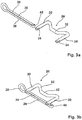
Fig. 1 mit dem erfindungsgemäßen Mittel; - Fig. 3a
- eine Explosionsdarstellung des erfindungsgemäßen Mittels zum Sichern einer Verbindung zweier stirnseitig zusammentreffender Balgelemente des Balges gemäß
Fig. 1 im unmontierten Zustand; - Fig. 3b
- die Mittel gemäß
Fig. 3b im montierten Zustand; - Fig. 4
- eine geschnitten dargestellte Draufsicht auf die Verbindung zweier stirnseitig zusammentreffender Balgelemente des Balges gemäß
Fig. 1 zusammen mit dem daran montierten Mittel zum Sichern der Verbindung, geschnitten entlang Linie IV - IV inFig. 2 ; - Fig. 5
- eine geschnitten dargestellte Seitenansicht auf die Verbindung gemäß
Fig. 4 zweier stirnseitig zusammentreffender Balgelemente des Balges gemäßFig. 1 zusammen mit dem daran montierten Mittel zum Sichern der Verbindung, geschnitten entlang Linie V - V inFig. 4 .
- Fig. 1
- a side view of a transition provided with a bellows between two articulated vehicles, wherein a lower part of the bellows attached to an upper part of the bellows and secured with the means according to the invention;
- Fig. 2
- an exploded view of a part of the bellows according to
Fig. 1 with the agent according to the invention; - Fig. 3a
- an exploded view of the means according to the invention for securing a connection of two frontally coincident bellows elements of the bellows according to
Fig. 1 in unmounted condition; - Fig. 3b
- the funds according to
Fig. 3b in the assembled state; - Fig. 4
- a sectional top view of the connection of two frontally coincident bellows elements of the bellows according to
Fig. 1 together with the means for securing the connection mounted thereon, cut along line IV - IV in FIGFig. 2 ; - Fig. 5
- a sectional side view of the compound according to
Fig. 4 according to two frontal Balgelemente of the bellowsFig. 1 together with the Attached thereto means for securing the connection, cut along line V - V inFig. 4 ,
In
Das Unterteil 18 ist derart mit dem Oberteil 16 verbunden, dass der über das Stirnende der Balgelemente 20 überstehende Abschnitt des Bügels 22 über ein freies Ende des Bügels 22 des Oberteils geschoben wird, sodass die beiden Stirnenden der Balgelemente 20 aneinanderstoßen und eine geschlossene Umhüllung des Übergangs 10 gewährleisten.The
Zur Sicherung dieser Verbindung zweier stirnseitig zusammentreffender Balgelemente 20 des Balges 14 wird ein Halteelement verwendet, wie es in den
Das Zwischenglied 32 der Spange 26 ist derart gebogen ausgebildet, dass ein am Zwischenglied 32 gradlinig ausgebildeter Mittelabschnitt 42 zum Bügel hin ausgerichtet ist. Gleichzeitig ist der Mittelabschnitt 42 senkrecht zu dem Bolzen 30 angeordnet.The
In den
Das Zwischenglied 32 ist federelastisch ausgebildet. In dem in den
Die Montage/Demontage des aus Spange 26 und Splint 28 bestehenden Halteelementes geschieht wie folgt:The assembly / disassembly of the retaining element consisting of
Zunächst wird der Bügel 22 mit seinem über das Stirnende des Balgelementes 20 hinausragenden Abschnitt auf ein Ende des benachbarten Bügels 22 des Oberteils 16 derart gestülpt, dass die vorbereiteten Öffnungen 24 miteinander fluchten. Anschließend wird die Spange 26 mit ihren Bolzen 30 durch die Öffnungen 24 hindurchgedrückt, wobei auf das Zwischenglied 32 eine so große Kraft ausgeübt wird, dass die Bolzen 30 die Aussparung 34 auf der anderen Seite des Bügels 22 deutlich freigeben. Durch diese Aussparungen 34 wird dann der kurze Schenkel 36 des Splintes 28 so weit hindurchgeschoben, dass der Stopper 40 des langen Schenkels 38 den hinteren Bolzen 30 hintergreift. Danach wird die Spange 26 losgelassen und das federelastische Zwischenglied 32 zieht die Bolzen 30 zurück, bis die Spange 28 am Bügel 22 zur Anlage kommt. Dabei behält das Zwischenglied 32 eine gewisse Federkraft, sodass der Splint 28 zuverlässig in den Aussparungen 30 gehalten wird.First, the
Zur Demontage wird analog in umgekehrter Reihenfolge vorgegangen, dass heißt, zunächst einmal wird die Spange 26 im Bereich der Bolzen 30 gegen die Federkraft des Zwischengliedes 32 so weit gedrückt, bis der Splint 28 frei liegt und ohne großen Kraftaufwand aus den Aussparungen 34 herausgezogen werden kann. Dabei wird der lange Schenkel 38 des Splints 28 so weit verbogen, dass der Stopper 40 an dem Bolzen 30 vorbeigeführt werden kann. Anschließend wird die Spange 28 aus den Bügeln 22 herausgezogen, sodass das Unterteil 18 ungesichert am Oberteil 16 hängt. Nun kann das Unterteil 18 in einfacher Weise vom Oberteil 16 gelöst werden.For disassembly is proceeded analogously in reverse order, that is, first of all, the
In einer anderen, hier nicht dargestellten Ausführungsform kann der Splint auch als Federsplint ausgebildet sein. In diesem Fall wird der Federsplint durch seine Federwirkung gegen Herausfallen gesichert.In another embodiment, not shown here, the split pin can also be designed as a spring split. In this case, the spring split is secured by its spring action against falling out.
- 1010
- Übergangcrossing
- 12, 12'12, 12 '
- Fahrzeugteilecar parts
- 1414
- Balgbellows
- 1616
- Oberteiltop
- 1818
- Unterteillower part
- 2020
- Balgelementbellows
- 2222
- Bügelhanger
- 2424
- Öffnungopening
- 2626
- Spangeclasp
- 2828
- Splintcotter
- 3030
- Bolzenbolt
- 3232
- Zwischengliedintermediary
- 3434
- Aussparungrecess
- 3636
- kurzer Schenkelshort thigh
- 3838
- langer Schenkellong thigh
- 4040
- Stopperstopper
- 4242
- Mittelabschnittmidsection
Claims (11)
dadurch gekennzeichnet,
dass das Halteelement (26) mindestens einen durch die sich überlappenden Bügel (22) hindurchreichenden Bolzen (30) umfasst, dessen die Bügel (22) überstehender Abschnitt eine Aussparung (34) zur Aufnahme des Sicherungselementes (28) aufweist.Means for securing a connection of two frontally in the circumferential direction of the bellows coinciding bellows elements of a bellows, wherein adjacent bellows members (20) by means of a bracket (22) are held together in the longitudinal direction of the bracket, wherein the bracket (22) of the frontally coincident bellows elements (20) partially overlap, the means securing the overlapping stirrups (22) and wherein the means comprises a retaining element (26) and at least one securing element (28),
characterized,
in that the holding element (26) comprises at least one bolt (30) extending through the overlapping brackets (22), the section of which projects over the brackets (22) having a recess (34) for receiving the securing element (28).
dadurch gekennzeichnet,
dass das Haltelement als eine im Wesentlichen U-förmige Spange (26) ausgebildet ist, die zwei parallel ausgerichtete Bolzen (30) und ein die Bolzen (30) miteinander verbindendes Zwischenglied (32) umfasst.Means for securing a connection between two frontally coinciding bellows elements of a bellows according to claim 1,
characterized,
in that the holding element is designed as a substantially U-shaped clip (26) which comprises two parallel aligned bolts (30) and an intermediate member (32) interconnecting the bolts (30).
dadurch gekennzeichnet,
dass das Zwischenglied (32) derart gebogen ausgebildet ist, dass das Zwischenglied (32) im eingebauten Zustand teilweise an einem der Bügel (22) zur Anlage kommt.Means for securing a connection between two frontally coinciding bellows elements of a bellows according to claim 2,
characterized,
that the intermediate member (32) is formed bent such that the intermediate member (32) in the installed state partly on one of the bracket (22) comes to rest.
dadurch gekennzeichnet,
dass das Zwischenglied (32) federelastische Eigenschaften besitzt.Means for securing a connection between two end-face meeting bellows elements of a bellows according to one of claims 2 or 3,
characterized,
that the intermediate member (32) has resilient properties.
dadurch gekennzeichnet,
dass das Zwischenglied (32) einen geradlinig ausgebildeten Mittelabschnitt (42) aufweist, sodass das Zwischenglied (32) mit dem gesamten Mittelabschnitt (42) am Bügel (22) zur Anlage kommt.Means for securing a connection between two frontally coinciding bellows elements of a bellows according to one of claims 2 to 4,
characterized,
in that the intermediate element (32) has a rectilinear central section (42), so that the intermediate element (32) comes into abutment with the entire central section (42) on the bracket (22).
dadurch gekennzeichnet,
dass die Spange (26) derart ausgelegt ist, dass die Spange (26) im montierten Zustand federelastisch gespannt ist,Means for securing a connection between two frontally coinciding bellows elements of a bellows according to one of claims 2 to 5,
characterized,
that the clip (26) is designed such that the clip (26) is stretched elastically in the mounted state,
dadurch gekennzeichnet,
dass die Aussparung (34) derart im Bolzen (30) angeordnet ist, dass das Zwischenglied (32) im montierten Zustand federelastisch gespannt ist, wobei der Mittelabschnitt (42) des Zwischengliedes (32) am Bügel (22) anliegt.Means for securing a connection between two frontally coinciding bellows elements of a bellows according to claim 6,
characterized,
that the recess (34) is arranged in the bolt (30), that the intermediate member (32) in the assembled state resiliently tensioned is, wherein the central portion (42) of the intermediate member (32) abuts the bracket (22).
dadurch gekennzeichnet,
dass das Sicherungselement als Standardsplint (28) ausgebildet ist und einen ersten, kürzeren Schenkel (36) und einen zweiten längeren Schenkel (38) aufweist.Means for securing a connection between two frontally coinciding bellows elements of a bellows according to one of the preceding claims,
characterized,
that the securing element is designed as Standardsplint (28) and having a first, shorter arm (36) and a second longer leg (38).
dadurch gekennzeichnet,
dass der zweite, längere Schenkel (38) an seinem, dem ersten, kürzeren Schenkel (36) überstehenden Bereich einen zum ersten Schenkel (36) hin gebogenen Stopper (40) aufweist.Means for securing a connection between two frontally coinciding bellows elements of a bellows according to claim 6,
characterized,
that has the second, longer leg (38) at its, to the first, shorter arm (36) projecting region a to the first leg (36) bent toward the stopper (40).
dadurch gekennzeichnet,
dass das Sicherungselement als Federsplint ausgebildet ist.Means for securing a connection between two frontally coinciding bellows elements of a bellows according to one of claims 1 to 7,
characterized,
that the securing element is designed as Federsplint.
dadurch gekennzeichnet,
dass die Verbindung im Seitenwand- und/oder Bodenbereich des Balges vorgenommen ist.Means for securing a connection between two frontally coinciding bellows elements of a bellows according to one of the preceding claims,
characterized,
that the connection is made in the sidewall and / or bottom area of the bellows.
Priority Applications (1)
| Application Number | Priority Date | Filing Date | Title |
|---|---|---|---|
| PL16206197T PL3205518T3 (en) | 2016-02-11 | 2016-12-22 | Means for securing a connection between two bellows elements of a bellows meeting at the front in the direction of the periphery |
Applications Claiming Priority (2)
| Application Number | Priority Date | Filing Date | Title |
|---|---|---|---|
| ATGM28/2016U AT15496U1 (en) | 2016-02-11 | 2016-02-11 | Means for securing a connection of two frontally circumferentially coincident bellows elements of a bellows |
| DE202016001988.1U DE202016001988U1 (en) | 2016-02-11 | 2016-03-24 | Means for securing a connection of two frontally circumferentially coincident bellows elements of a bellows |
Publications (2)
| Publication Number | Publication Date |
|---|---|
| EP3205518A1 true EP3205518A1 (en) | 2017-08-16 |
| EP3205518B1 EP3205518B1 (en) | 2020-02-12 |
Family
ID=56498381
Family Applications (1)
| Application Number | Title | Priority Date | Filing Date |
|---|---|---|---|
| EP16206197.2A Active EP3205518B1 (en) | 2016-02-11 | 2016-12-22 | Means for securing a connection between two bellows elements of a bellows meeting at the front in the direction of the periphery |
Country Status (5)
| Country | Link |
|---|---|
| EP (1) | EP3205518B1 (en) |
| AT (1) | AT15496U1 (en) |
| DE (1) | DE202016001988U1 (en) |
| ES (1) | ES2774370T3 (en) |
| PL (1) | PL3205518T3 (en) |
Cited By (3)
| Publication number | Priority date | Publication date | Assignee | Title |
|---|---|---|---|---|
| EP3495227A1 (en) | 2017-12-05 | 2019-06-12 | Hübner GmbH & Co. KG | Transition to be mounted between two vehicles with a jointed connection |
| WO2021090268A1 (en) * | 2019-11-08 | 2021-05-14 | Leonardo S.P.A. | Closure system of the interconnection of transport units connected to each other in a convoy |
| IT202000000310A1 (en) * | 2019-11-08 | 2021-07-10 | Leonardo Spa | CLOSURE SYSTEM FOR THE INTERCONNECTION OF TRANSPORT UNITS CONNECTED TO EACH ONE IN A CONVEYANCE |
Families Citing this family (2)
| Publication number | Priority date | Publication date | Assignee | Title |
|---|---|---|---|---|
| IT202000003671A1 (en) * | 2020-02-21 | 2021-08-21 | P E I Protezioni Elaborazioni Ind S R L | FIXING DEVICE, INSULATION GROUP AND CORRESPONDING PROCEDURE. |
| SE544961C2 (en) * | 2020-05-11 | 2023-02-07 | Dellner Couplers Ab | Convolute for a bellows for a gangway, bellows for a gangway and multi-car vehicle |
Citations (4)
| Publication number | Priority date | Publication date | Assignee | Title |
|---|---|---|---|---|
| DE10337301B3 (en) * | 2003-08-14 | 2005-04-07 | Knorr-Bremse Systeme für Nutzfahrzeuge GmbH | Bolt especially for motor vehicle components is manufactured by cold extrusion, whereby through-opening is formed in bolt and at least partially enclosed by two legs which are then compressed by cold forming |
| DE10154033B4 (en) | 2000-11-25 | 2006-10-19 | Hübner GmbH | Bellows a transition between two articulated vehicles |
| EP1810852A1 (en) * | 2006-01-19 | 2007-07-25 | HÜBNER GmbH | Bellows of a passage between two articulated vehicles |
| EP2106984A1 (en) * | 2008-03-31 | 2009-10-07 | ATG Autotechnik GmbH | Folded lining |
Family Cites Families (4)
| Publication number | Priority date | Publication date | Assignee | Title |
|---|---|---|---|---|
| FR1537125A (en) * | 1967-07-12 | 1968-08-23 | Ferodo Sa | Clutch refinements |
| US4439897A (en) * | 1981-12-22 | 1984-04-03 | Preformed Line Products Company | Dead-end appliance for linear bodies |
| DE10257889B4 (en) * | 2002-12-11 | 2005-04-21 | Minebea Co., Ltd. | Device for connecting a stator of an electric motor to a motor housing |
| DE102013011656B4 (en) * | 2013-07-12 | 2021-05-12 | Knorr-Bremse Systeme für Nutzfahrzeuge GmbH | Brake pad holder for a disc brake for a commercial vehicle |
-
2016
- 2016-02-11 AT ATGM28/2016U patent/AT15496U1/en not_active IP Right Cessation
- 2016-03-24 DE DE202016001988.1U patent/DE202016001988U1/en not_active Expired - Lifetime
- 2016-12-22 PL PL16206197T patent/PL3205518T3/en unknown
- 2016-12-22 ES ES16206197T patent/ES2774370T3/en active Active
- 2016-12-22 EP EP16206197.2A patent/EP3205518B1/en active Active
Patent Citations (4)
| Publication number | Priority date | Publication date | Assignee | Title |
|---|---|---|---|---|
| DE10154033B4 (en) | 2000-11-25 | 2006-10-19 | Hübner GmbH | Bellows a transition between two articulated vehicles |
| DE10337301B3 (en) * | 2003-08-14 | 2005-04-07 | Knorr-Bremse Systeme für Nutzfahrzeuge GmbH | Bolt especially for motor vehicle components is manufactured by cold extrusion, whereby through-opening is formed in bolt and at least partially enclosed by two legs which are then compressed by cold forming |
| EP1810852A1 (en) * | 2006-01-19 | 2007-07-25 | HÜBNER GmbH | Bellows of a passage between two articulated vehicles |
| EP2106984A1 (en) * | 2008-03-31 | 2009-10-07 | ATG Autotechnik GmbH | Folded lining |
Cited By (4)
| Publication number | Priority date | Publication date | Assignee | Title |
|---|---|---|---|---|
| EP3495227A1 (en) | 2017-12-05 | 2019-06-12 | Hübner GmbH & Co. KG | Transition to be mounted between two vehicles with a jointed connection |
| WO2021090268A1 (en) * | 2019-11-08 | 2021-05-14 | Leonardo S.P.A. | Closure system of the interconnection of transport units connected to each other in a convoy |
| IT202000000310A1 (en) * | 2019-11-08 | 2021-07-10 | Leonardo Spa | CLOSURE SYSTEM FOR THE INTERCONNECTION OF TRANSPORT UNITS CONNECTED TO EACH ONE IN A CONVEYANCE |
| US11873166B2 (en) | 2019-11-08 | 2024-01-16 | Leonardo S.P.A. | Closure system of the interconnection of transport units connected to each other in a convoy |
Also Published As
| Publication number | Publication date |
|---|---|
| EP3205518B1 (en) | 2020-02-12 |
| DE202016001988U1 (en) | 2016-07-06 |
| ES2774370T3 (en) | 2020-07-20 |
| PL3205518T3 (en) | 2020-06-29 |
| AT15496U1 (en) | 2017-10-15 |
Similar Documents
| Publication | Publication Date | Title |
|---|---|---|
| EP3205518B1 (en) | Means for securing a connection between two bellows elements of a bellows meeting at the front in the direction of the periphery | |
| EP3464013B1 (en) | Connection between components with different coefficients of thermal expansion | |
| WO2008107164A1 (en) | Clip for attaching pipes | |
| EP0401659A1 (en) | Fixing of a mud flap | |
| EP3472403B1 (en) | Device for fastening a panel-shaped component in a receiving groove of a carrying rail | |
| EP3286440A1 (en) | Device for securing to a component | |
| DE102019108910A1 (en) | Multi-part adjustment element for a tolerance compensation arrangement | |
| DE102009028458A1 (en) | Guide element, particularly pendulum support for coupled connection of two components, has bar element and coupling element for coupling guide element to component | |
| DE19923487B4 (en) | Abutment with molding for attaching control cables | |
| EP1388308B1 (en) | Assembly with a first and second constuction part and a mounting bracket for temporary holding and fixing the first construction part to the second construction part. | |
| EP2787265B1 (en) | Corner angle | |
| EP2722465B1 (en) | Quick tensioning nut | |
| DE102008063582A1 (en) | Circular pipe clamp, has clamp ring with opening, pipe inserted into area of circumference of opening of ring, and clamping screw exhibiting thread-free shaft section covered over its entire length by flexible element | |
| DE102009002470A1 (en) | Clamp construction as well as load switch bar or isolator with clamp construction | |
| DE2260187A1 (en) | BRAKE ACTUATOR DEVICE, IN PARTICULAR FOR DRUM BRAKES | |
| DE102014114319A1 (en) | Motor vehicle door lock | |
| DE102018001280A1 (en) | Spring tensioning device and method for tensioning axle springs on spring links of vehicles | |
| EP2221490B1 (en) | Single part fastening element for assembling a rod element to a fitting rail | |
| DE202017102151U1 (en) | Airbag module and steering wheel | |
| DE102006048064B4 (en) | fastening device | |
| EP3359825A1 (en) | Connecting device for rigidly connecting a first pipe to a second pipe | |
| DE4335267A1 (en) | Connecting element | |
| EP3214240B1 (en) | Motor vehicle door handle assembly having a securing element with a limit stop | |
| EP3239537B1 (en) | Fixing device and method for its manufacture | |
| DE102020100752A1 (en) | Connector, connection arrangement and method for connecting two threaded rods at an adjustable angle |
Legal Events
| Date | Code | Title | Description |
|---|---|---|---|
| PUAI | Public reference made under article 153(3) epc to a published international application that has entered the european phase |
Free format text: ORIGINAL CODE: 0009012 |
|
| STAA | Information on the status of an ep patent application or granted ep patent |
Free format text: STATUS: THE APPLICATION HAS BEEN PUBLISHED |
|
| AK | Designated contracting states |
Kind code of ref document: A1 Designated state(s): AL AT BE BG CH CY CZ DE DK EE ES FI FR GB GR HR HU IE IS IT LI LT LU LV MC MK MT NL NO PL PT RO RS SE SI SK SM TR |
|
| AX | Request for extension of the european patent |
Extension state: BA ME |
|
| STAA | Information on the status of an ep patent application or granted ep patent |
Free format text: STATUS: REQUEST FOR EXAMINATION WAS MADE |
|
| 17P | Request for examination filed |
Effective date: 20170905 |
|
| RBV | Designated contracting states (corrected) |
Designated state(s): AL AT BE BG CH CY CZ DE DK EE ES FI FR GB GR HR HU IE IS IT LI LT LU LV MC MK MT NL NO PL PT RO RS SE SI SK SM TR |
|
| RIC1 | Information provided on ipc code assigned before grant |
Ipc: B62D 47/02 20060101ALI20190716BHEP Ipc: B61D 17/22 20060101ALI20190716BHEP Ipc: B60D 5/00 20060101AFI20190716BHEP |
|
| GRAP | Despatch of communication of intention to grant a patent |
Free format text: ORIGINAL CODE: EPIDOSNIGR1 |
|
| STAA | Information on the status of an ep patent application or granted ep patent |
Free format text: STATUS: GRANT OF PATENT IS INTENDED |
|
| INTG | Intention to grant announced |
Effective date: 20190910 |
|
| GRAS | Grant fee paid |
Free format text: ORIGINAL CODE: EPIDOSNIGR3 |
|
| GRAA | (expected) grant |
Free format text: ORIGINAL CODE: 0009210 |
|
| STAA | Information on the status of an ep patent application or granted ep patent |
Free format text: STATUS: THE PATENT HAS BEEN GRANTED |
|
| AK | Designated contracting states |
Kind code of ref document: B1 Designated state(s): AL AT BE BG CH CY CZ DE DK EE ES FI FR GB GR HR HU IE IS IT LI LT LU LV MC MK MT NL NO PL PT RO RS SE SI SK SM TR |
|
| REG | Reference to a national code |
Ref country code: GB Ref legal event code: FG4D Free format text: NOT ENGLISH |
|
| REG | Reference to a national code |
Ref country code: CH Ref legal event code: EP |
|
| REG | Reference to a national code |
Ref country code: AT Ref legal event code: REF Ref document number: 1231620 Country of ref document: AT Kind code of ref document: T Effective date: 20200215 |
|
| REG | Reference to a national code |
Ref country code: IE Ref legal event code: FG4D Free format text: LANGUAGE OF EP DOCUMENT: GERMAN |
|
| REG | Reference to a national code |
Ref country code: DE Ref legal event code: R096 Ref document number: 502016008695 Country of ref document: DE |
|
| REG | Reference to a national code |
Ref country code: ES Ref legal event code: FG2A Ref document number: 2774370 Country of ref document: ES Kind code of ref document: T3 Effective date: 20200720 |
|
| PG25 | Lapsed in a contracting state [announced via postgrant information from national office to epo] |
Ref country code: RS Free format text: LAPSE BECAUSE OF FAILURE TO SUBMIT A TRANSLATION OF THE DESCRIPTION OR TO PAY THE FEE WITHIN THE PRESCRIBED TIME-LIMIT Effective date: 20200212 Ref country code: FI Free format text: LAPSE BECAUSE OF FAILURE TO SUBMIT A TRANSLATION OF THE DESCRIPTION OR TO PAY THE FEE WITHIN THE PRESCRIBED TIME-LIMIT Effective date: 20200212 Ref country code: NO Free format text: LAPSE BECAUSE OF FAILURE TO SUBMIT A TRANSLATION OF THE DESCRIPTION OR TO PAY THE FEE WITHIN THE PRESCRIBED TIME-LIMIT Effective date: 20200512 |
|
| REG | Reference to a national code |
Ref country code: LT Ref legal event code: MG4D |
|
| REG | Reference to a national code |
Ref country code: NL Ref legal event code: MP Effective date: 20200212 |
|
| PG25 | Lapsed in a contracting state [announced via postgrant information from national office to epo] |
Ref country code: IS Free format text: LAPSE BECAUSE OF FAILURE TO SUBMIT A TRANSLATION OF THE DESCRIPTION OR TO PAY THE FEE WITHIN THE PRESCRIBED TIME-LIMIT Effective date: 20200612 Ref country code: LV Free format text: LAPSE BECAUSE OF FAILURE TO SUBMIT A TRANSLATION OF THE DESCRIPTION OR TO PAY THE FEE WITHIN THE PRESCRIBED TIME-LIMIT Effective date: 20200212 Ref country code: SE Free format text: LAPSE BECAUSE OF FAILURE TO SUBMIT A TRANSLATION OF THE DESCRIPTION OR TO PAY THE FEE WITHIN THE PRESCRIBED TIME-LIMIT Effective date: 20200212 Ref country code: BG Free format text: LAPSE BECAUSE OF FAILURE TO SUBMIT A TRANSLATION OF THE DESCRIPTION OR TO PAY THE FEE WITHIN THE PRESCRIBED TIME-LIMIT Effective date: 20200512 Ref country code: HR Free format text: LAPSE BECAUSE OF FAILURE TO SUBMIT A TRANSLATION OF THE DESCRIPTION OR TO PAY THE FEE WITHIN THE PRESCRIBED TIME-LIMIT Effective date: 20200212 Ref country code: GR Free format text: LAPSE BECAUSE OF FAILURE TO SUBMIT A TRANSLATION OF THE DESCRIPTION OR TO PAY THE FEE WITHIN THE PRESCRIBED TIME-LIMIT Effective date: 20200513 |
|
| PG25 | Lapsed in a contracting state [announced via postgrant information from national office to epo] |
Ref country code: NL Free format text: LAPSE BECAUSE OF FAILURE TO SUBMIT A TRANSLATION OF THE DESCRIPTION OR TO PAY THE FEE WITHIN THE PRESCRIBED TIME-LIMIT Effective date: 20200212 |
|
| PG25 | Lapsed in a contracting state [announced via postgrant information from national office to epo] |
Ref country code: SM Free format text: LAPSE BECAUSE OF FAILURE TO SUBMIT A TRANSLATION OF THE DESCRIPTION OR TO PAY THE FEE WITHIN THE PRESCRIBED TIME-LIMIT Effective date: 20200212 Ref country code: DK Free format text: LAPSE BECAUSE OF FAILURE TO SUBMIT A TRANSLATION OF THE DESCRIPTION OR TO PAY THE FEE WITHIN THE PRESCRIBED TIME-LIMIT Effective date: 20200212 Ref country code: LT Free format text: LAPSE BECAUSE OF FAILURE TO SUBMIT A TRANSLATION OF THE DESCRIPTION OR TO PAY THE FEE WITHIN THE PRESCRIBED TIME-LIMIT Effective date: 20200212 Ref country code: EE Free format text: LAPSE BECAUSE OF FAILURE TO SUBMIT A TRANSLATION OF THE DESCRIPTION OR TO PAY THE FEE WITHIN THE PRESCRIBED TIME-LIMIT Effective date: 20200212 Ref country code: PT Free format text: LAPSE BECAUSE OF FAILURE TO SUBMIT A TRANSLATION OF THE DESCRIPTION OR TO PAY THE FEE WITHIN THE PRESCRIBED TIME-LIMIT Effective date: 20200705 Ref country code: SK Free format text: LAPSE BECAUSE OF FAILURE TO SUBMIT A TRANSLATION OF THE DESCRIPTION OR TO PAY THE FEE WITHIN THE PRESCRIBED TIME-LIMIT Effective date: 20200212 Ref country code: RO Free format text: LAPSE BECAUSE OF FAILURE TO SUBMIT A TRANSLATION OF THE DESCRIPTION OR TO PAY THE FEE WITHIN THE PRESCRIBED TIME-LIMIT Effective date: 20200212 |
|
| REG | Reference to a national code |
Ref country code: DE Ref legal event code: R097 Ref document number: 502016008695 Country of ref document: DE |
|
| PLBE | No opposition filed within time limit |
Free format text: ORIGINAL CODE: 0009261 |
|
| STAA | Information on the status of an ep patent application or granted ep patent |
Free format text: STATUS: NO OPPOSITION FILED WITHIN TIME LIMIT |
|
| 26N | No opposition filed |
Effective date: 20201113 |
|
| PG25 | Lapsed in a contracting state [announced via postgrant information from national office to epo] |
Ref country code: SI Free format text: LAPSE BECAUSE OF FAILURE TO SUBMIT A TRANSLATION OF THE DESCRIPTION OR TO PAY THE FEE WITHIN THE PRESCRIBED TIME-LIMIT Effective date: 20200212 |
|
| REG | Reference to a national code |
Ref country code: CH Ref legal event code: PL |
|
| GBPC | Gb: european patent ceased through non-payment of renewal fee |
Effective date: 20201222 |
|
| PG25 | Lapsed in a contracting state [announced via postgrant information from national office to epo] |
Ref country code: MC Free format text: LAPSE BECAUSE OF FAILURE TO SUBMIT A TRANSLATION OF THE DESCRIPTION OR TO PAY THE FEE WITHIN THE PRESCRIBED TIME-LIMIT Effective date: 20200212 |
|
| REG | Reference to a national code |
Ref country code: BE Ref legal event code: MM Effective date: 20201231 |
|
| PG25 | Lapsed in a contracting state [announced via postgrant information from national office to epo] |
Ref country code: IE Free format text: LAPSE BECAUSE OF NON-PAYMENT OF DUE FEES Effective date: 20201222 Ref country code: LU Free format text: LAPSE BECAUSE OF NON-PAYMENT OF DUE FEES Effective date: 20201222 |
|
| PG25 | Lapsed in a contracting state [announced via postgrant information from national office to epo] |
Ref country code: LI Free format text: LAPSE BECAUSE OF NON-PAYMENT OF DUE FEES Effective date: 20201231 Ref country code: GB Free format text: LAPSE BECAUSE OF NON-PAYMENT OF DUE FEES Effective date: 20201222 Ref country code: CH Free format text: LAPSE BECAUSE OF NON-PAYMENT OF DUE FEES Effective date: 20201231 |
|
| PG25 | Lapsed in a contracting state [announced via postgrant information from national office to epo] |
Ref country code: TR Free format text: LAPSE BECAUSE OF FAILURE TO SUBMIT A TRANSLATION OF THE DESCRIPTION OR TO PAY THE FEE WITHIN THE PRESCRIBED TIME-LIMIT Effective date: 20200212 Ref country code: MT Free format text: LAPSE BECAUSE OF FAILURE TO SUBMIT A TRANSLATION OF THE DESCRIPTION OR TO PAY THE FEE WITHIN THE PRESCRIBED TIME-LIMIT Effective date: 20200212 Ref country code: CY Free format text: LAPSE BECAUSE OF FAILURE TO SUBMIT A TRANSLATION OF THE DESCRIPTION OR TO PAY THE FEE WITHIN THE PRESCRIBED TIME-LIMIT Effective date: 20200212 |
|
| PG25 | Lapsed in a contracting state [announced via postgrant information from national office to epo] |
Ref country code: MK Free format text: LAPSE BECAUSE OF FAILURE TO SUBMIT A TRANSLATION OF THE DESCRIPTION OR TO PAY THE FEE WITHIN THE PRESCRIBED TIME-LIMIT Effective date: 20200212 Ref country code: AL Free format text: LAPSE BECAUSE OF FAILURE TO SUBMIT A TRANSLATION OF THE DESCRIPTION OR TO PAY THE FEE WITHIN THE PRESCRIBED TIME-LIMIT Effective date: 20200212 |
|
| PG25 | Lapsed in a contracting state [announced via postgrant information from national office to epo] |
Ref country code: BE Free format text: LAPSE BECAUSE OF NON-PAYMENT OF DUE FEES Effective date: 20201231 |
|
| PGFP | Annual fee paid to national office [announced via postgrant information from national office to epo] |
Ref country code: IT Payment date: 20221230 Year of fee payment: 7 |
|
| P01 | Opt-out of the competence of the unified patent court (upc) registered |
Effective date: 20230911 |
|
| PGFP | Annual fee paid to national office [announced via postgrant information from national office to epo] |
Ref country code: FR Payment date: 20231219 Year of fee payment: 8 Ref country code: DE Payment date: 20231214 Year of fee payment: 8 Ref country code: CZ Payment date: 20231208 Year of fee payment: 8 Ref country code: AT Payment date: 20231214 Year of fee payment: 8 |
|
| PGFP | Annual fee paid to national office [announced via postgrant information from national office to epo] |
Ref country code: PL Payment date: 20231211 Year of fee payment: 8 |
|
| PGFP | Annual fee paid to national office [announced via postgrant information from national office to epo] |
Ref country code: ES Payment date: 20240118 Year of fee payment: 8 |